1
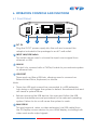
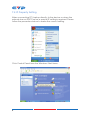
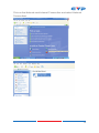
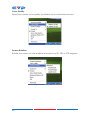
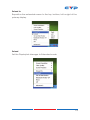
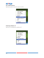
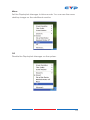
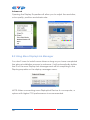
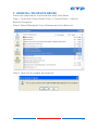
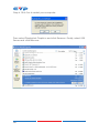
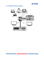
CDL-165ETHG ETHERNET/USB to HDMI/VGA Display Converter Operation Manual DISCLAIMERS The information in this manual has been carefully checked and is believed to be accurate. Cypress Technology assumes no responsibility for any infringements of patents or other rights of third parties which may result from its use. Cypress Technology assumes no responsibility for any inaccuracies that may be contained in this document. Cypress also makes no commitment to update or to keep current the information contained in this document. Cypress Technology reserves the right to make improvements to this document and/or product at any time and without notice. COPYRIGHT NOTICE No part of this document may be reproduced, transmitted, transcribed, stored in a retrieval system, or any of its part translated into any language or computer file, in any form or by any means— electronic, mechanical, magnetic, optical, chemical, manual, or otherwise—without express written permission and consent from Cypress Technology. © Copyright 2011 by Cypress Technology. All Rights Reserved. Version 1.1 August 2011 TRADEMARK ACKNOWLEDGMENTS All products or service names mentioned in this document may be trademarks of the companies with which they are associated. SAFETY PRECAUTIONS Please read all instructions before attempting to unpack, install or operate this equipment and before connecting the power supply. Please keep the following in mind as you unpack and install this equipment: • Always follow basic safety precautions to reduce the risk of fire, electrical shock and injury to persons. • To prevent fire or shock hazard, do not expose the unit to rain, moisture or install this product near water. • Never spill liquid of any kind on or into this product. • Never push an object of any kind into this product through any openings or empty slots in the unit, as you may damage parts inside the unit. • Do not attach the power supply cabling to building surfaces. • Use only the supplied power supply unit (PSU). Do not use the PSU if it is damaged. • Do not allow anything to rest on the power cabling or allow any weight to be placed upon it or any person walk on it. • To protect the unit from overheating, do not block any vents or openings in the unit housing that provide ventilation and allow for sufficient space for air to circulate around the unit. REVISION HISTORY VERSION NO. DATE DD/MM/YY SUMMARY OF CHANGE VS1 19/12/11 First Release CONTENTS 1. Introduction�������������������������������������������� 1 2. Applications������������������������������������������� 1 3. Package Contents�������������������������������� 1 4. System Requirements���������������������������� 1 5. Features�������������������������������������������������� 2 6. Operation Controls and Functions������� 3 6.1 Front Panel����������������������������������������3 6.2 Rear Panel�����������������������������������������4 7. Software Installation������������������������������ 5 7.1 Install DispalyLink Software��������������5 7.2 Install USB Server Software���������������5 7.3 Using USB Server�������������������������������7 7.4 IP Property Setting����������������������������8 8. Using DisplayLink Manager���������������� 11 8.1 Using DisplayLink Manager�����������11 8.2 Using More DisplayLink Manager�16 9. Uninstall the Device Driver������������������ 17 10. Connection Diagram������������������������ 19 11. Troubleshooting��������������������������������� 20 12. Specifications������������������������������������ 21 13. Acronyms������������������������������������������� 22 1. INTRODUCTION The device that can send audio/video signals from a Notebook/PC over a local area network through regular Ethernet cables to a TV which can be used as the primary display. When a keyboard and mouse are plugged in, the device will lets you to edit word processing documents and play your music/movies on a TV. Supporting a direct connection up to 100 meters away when using network cables, this gadget also includes two USB ports which let users operate printers, scanners and other USB devices at the same time, just like a PC. This is useful in many different scenarios, for example: During meetings each attendee would be able to access a projector from their laptop without having to fumble with any cables as long as they are connected to the network. This device can also be used as a simple USB to HDMI signal converter thanks to its mini USB input port. 2. APPLICATIONS • Educational teaching • Home entertainment • Office network • Home network 3. PACKAGE CONTENTS • Ethernet/USB to HDMI/VGA Converter • 5 V/2.6 A DC power adaptor • User Manual • Driver CD 4. SYSTEM REQUIREMENTS • System Hardware Requirements: 2.4 GHz single core CPU with at least 1 GB RAM for optimal performance. • Operating Systems: -- Windows XP Home or Professional SP2 -- Windows Vista/Windows 7 Note: -- The MAC OS driver does not support connection over ethernet 1 whereas connection via USB supports Mac OS X (v10.4.11 and v10.5.6) • USB Port Extension: -- An available USB 2.0 port with USB to mini-USB cable • Network Extension: -- An available Ethernet port at home or a commercial network with RJ-45 cable 5. FEATURES • Supports HDMI & VGA outputs • 16/32-bit Color for high-quality images • HD resolutions up to 1920×1080 • HDMI and RGB display connectivity • EDID selectable with switch for VGA or HDMI output • Experience the complete PC environment on a TV from 100m away • Allows a TV to act as the primary PC display and the use of keyboard and mouse to browse the internet, use Microsoft Office, watch/listen to movies/music from any networked computer • Supports high performance 16-bit stereo, 48 kHz audio sampling • Supports TCP/IP ethernet protocols • Supports 10/100/1000 Mbps ethernet • Extend or mirror audio and video through a network or USB cable to an HDMI display • Share HDMI display with multiple users through your existing office or home IP network • Add an HDMI display to your computer through a USB 2.0 port • Supports mirror and extended video modes 2 6. OPERATION CONTROLS AND FUNCTIONS 6.1 Front Panel DC 5V 1 LAN USB USB IN INPUT LAN IN USB PORT 2 3 4 5 1 DC 5V Plug the 5V DC power supply into the unit and connect the adaptor included in the package to an AC wall outlet. 2 INPUT LAN/USB Switch This switch allows users to choose the input source signal from ethernet or USB. 3 LAN IN This slot is to connect with a CAT5e/6 cable to your network system or ethernet hub. 4 USB PORT These ports act like a USB hub, allowing users to connect an External Hard Drive, Keyboard, or Mouse. Note: • These two USB ports cannot be connected to a USB extension hub,doing so will trigger the system to detect the external Hub and will cause a system failure. • Before removing the USB device, the user must follow the USB devices hardware removal procedure for the relevant operating system. Failure to do so will cause the system to crash. 5 Mini USB IN This port supports mirror or video extension (via USB cable) from the PC/laptop source device to your HDMI display, including both video and audio output signals. 3 6.2 Rear Panel HDMI OUT HDMI OFF VGA 1 EDID AUDIO 2 3 OUT VGA 4 1 HDMI OUT Connect to the HDMI TV/display with HDMI cable for video and audio output. 2 EDID Control Switch The default setting for this switch is on HDMI, leave the switch here as long as the connected display is compatible. When the switch is set to 'OFF' this will allow use of the built-in EDID (the input source device must be re-powered/restarted in order for this to function). However, switching from 'OFF' to 'HDMI' or 'VGA' will not require a restart. Built in EDID as follow: 640×480, 720×480, 768×576, 800×600, 1024×768, 1280×720, 1280×1024, 1360×768, 1366×768, 1440×900, 1600×1200, 1680×1050, 1920×1080. 3 AUDIO OUT Connect with 3.5 mm phone jack cable to active speakers or PC monitor with speaker input for audio output. 4 VGA OUT 4 Connect to display monitor or TV that has a D-Sub 15-pin input for VGA video signal output. 7. SOFTWARE INSTALLATION The following sections list the procedures to follow when installing the USB to HDMI and USB device drivers. Insert the provided CD into your CD-ROM drive, then begin the USB Install Disc and follow the below steps to install the driver. 7.1 Install DispalyLink Software Insert the CD driver included in the package and double click on the DisplayLink icon to execute the setup. 7.2 Install USB Server Software Double click on the USBServer Setup icon to execute the set up and click finish when the setup is complete. 5 When both the DisplayLink and USB Server drivers have been installed the USB Server’s icon should appear on the desktop and in the system tray. 6 7.3 Using USB Server Double click on the 'Launch USB Server' icon from the desktop or from the icon in the system tray and the USB Server window will appear on the desktop. Connect both the PC/Laptop and the unit with a RJ-45 patch cable. Click on Search ensuring that you have set the INPUT switch on the device to LAN. Once the connection is done click on Connect Device next to the Search for both Display and Media. When the connection is done the Status will change to 'Locally Connected'. 7 7.4 IP Property Setting When connecting PC/Laptop directly to the device or when the network has no DHCP server a special IP setting is required. Please follow the procedure below to make the correct setting. Click Control Panel from the Windows Start Menu. 8 Click on the Network and Internet Connection and select Network Connections. 9 Double click on the Local Area Connection Double click on the Internet Protocol (TCP/IP) Click on “Use the follow IP address” and set the IP address and Subnet mask. The IP address setting should remain at 169.254.10.X (X can be 0~9&11~255) and Subnet mask can remain as 255.255.0.0 appear with “” mark. When disconnecting click on “Disconnect Device”. 10 8. USING DISPLAYLINK MANAGER 8.1 Using DisplayLink Manager After the driver is installed, a utility (DisplayLink Manager) will automatically appear in the system tray. The utility allows you to quickly change the settings and resolution for DisplayLink Manager. Right click on the icon will bring out the context menu. Screen Resolution Select the screen resolution (available only in extended mode).NOTE: When the display has a built in EDID the screen will show the display's resolution, if no EDID is present the screen has the following resolution (see image on the right.) 11 Color Quality Select the screen color quality (available only in extended mode). Screen Rotation Rotate the screen on the additional monitor by 90, 180 or 270 degrees. 12 Extend to Reposition the extended screen to the top, bottom, left or right of the primary display. Extend Set the DisplayLink Manager to Extended mode. 13 Set as Main Monitor Set the monitor to be the main monitor. Notebook Monitor off Set the PC/notebook's monitor off. 14 Mirror Set the DisplayLink Manager to Mirror mode. You can see the same desktop image on the additional monitor. Off Disable the DisplayLink Manager on the system. 15 Advanced Opening the Display Properties will allow you to adjust the resolution, color quality, position and refresh rate. 8.2 Using More DisplayLink Manager You don’t have to install a new driver as long as you have completed the above installation process in advance. It will automatically define the ID of the new Display Link Manager and will list everything in the Display properties or the display manager menu. NOTE: When connecting more DisplayLink Device to a computer, a system with higher CPU performance is recommended. 16 9. UNINSTALL THE DEVICE DRIVER Follow the steps below to uninstall the Multi View driver. Step 1: Open the Control Panel: Start → Control Panel → Add or Remove Programs. Step 2: Select DisplayLink Core Software and click Remove. Step 3: Click Yes to confirm the removal. 17 Step 4: Click Yes to restart your computer. Then select DisplayLink Graphics and click Remove. Finally, select USB Server and click Remove. 18 10. CONNECTION DIAGRAM Notebook OR Notebook PC Mini-USB Wireless Ethernet Hub DC 5V LAN USB USB Keyboard or Mouse USB IN INPUT LAN IN USB PORT USB HDMI OUT HDMI OFF VGA EDID AUDIO OUT HDMI HDD or USB Flash Disk VGA VGA TV/Monitor TV/Monitor OR Amplifier Active Speakers 19 11. TROUBLESHOOTING Situation Check Point The device driver has been installed, but the DisplayLink Manager is not working Make sure that the computer has been restarted after the driver installation. Check all the connectors are plugged in correctly. Make sure the USB port that you are using is USB 2.0. compliant Check the additional monitor is connected correctly and the power is on. Chaeck the operating system of the computer, the DisplayLink Manager is compatible with Windows XP, Vista (32bit) and Windows 7. Try a different USB 2.0 port or computer. Check USB cable’s specification. DVD player is not working when moved to the extended display 1. Try another software player. The mouse does not move passed the right side during extended desk top mode. 1. Check the display settings and make sure that your display number 2 is on the right hand side of display number 1. 20 12. SPECIFICATIONS Video Resolution Up to 1600×1200 /1920×1080 (wide) Video Input 1×Ethernet RJ-45, 1×USB 2.0 Network Protocol TCP/IP Video Output Ports 1×HDMI, 1×D-Sub 15pin VGA Extender Ports 2×USB Hubs (A type) Audio Output 1Vp-p 47 KΩ 3.5 mm Phone jack OS Support Windows XP SP2, Vista and 7 Power Supply 5 V DC/2.6 A (US/EU standards, CE/FCC/UL certified) ESD Protection Human body model: ±8 kV (air-gap discharge) ±4 kV (contact discharge) Dimensions 119 mm (W)×88 mm (D)×25 mm (H) Weight 120 g Chassis Material Plastic Silkscreen Color Black Power Consumption 11 W Operating Temperature 0 ˚C~40 ˚C / 32 ˚F~104 ˚F Storage Temperature −20 ˚C~60˚C/ −4 ˚F ~ 140 ˚F Relative Humidity 20~90 % RH (non-condensing) 21 13. ACRONYMS ACRONYM COMPLETE TERM ARC Audio Return Channel CEC Consumer Electronics Control EDID Extended Display Identification Data HEAC HDMI Ethernet & Audio Return Channel HEC HDMI Ethernet Channel HDCP High-bandwidth Digital content protection HDMI High-Definition Multimedia Interface 22 CYPRESS TECHNOLOGY CO., LTD Home page: http://www.cypress.com.tw