1
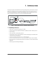
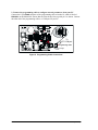
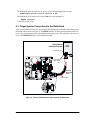
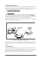
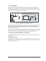
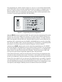
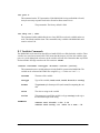
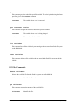
RabbitLink (EG2100) Network Programming Gateway User’s Manual 019–0090 • 020222–B RabbitLink (EG2100) User’s Manual Part Number 019-0090 • 020222–B • Printed in U.S.A. ©2001 Z-World Inc. • All rights reserved. Z-World reserves the right to make changes and improvements to its products without providing notice. Notice to Users Z-WORLD PRODUCTS ARE NOT AUTHORIZED FOR USE AS CRITICAL COMPONENTS IN LIFE-SUPPORT DEVICES OR SYSTEMS UNLESS A SPECIFIC WRITTEN AGREEMENT REGARDING SUCH INTENDED USE IS ENTERED INTO BETWEEN THE CUSTOMER AND Z-WORLD PRIOR TO USE. Life-support devices or systems are devices or systems intended for surgical implantation into the body or to sustain life, and whose failure to perform, when properly used in accordance with instructions for use provided in the labeling and user’s manual, can be reasonably expected to result in significant injury. No complex software or hardware system is perfect. Bugs are always present in a system of any size. In order to prevent danger to life or property, it is the responsibility of the system designer to incorporate redundant protective mechanisms appropriate to the risk involved. All Z-World products are 100 percent functionally tested. Additional testing may include visual quality control inspections or mechanical defects analyzer inspections. Specifications are based on characterization of tested sample units rather than testing over temperature and voltage of each unit. Z-World may qualify components to operate within a range of parameters that is different from the manufacturer’s recommended range. This strategy is believed to be more economical and effective. Additional testing or burn-in of an individual unit is available by special arrangement. Trademarks Rabbit 2000 is a trademark of Rabbit Semiconductor. Dynamic C is a registered trademark of Z-World Inc. ii Z-World, Inc. Rabbit Semiconductor 2900 Spafford Street Davis, California 95616-6800 USA 2932 Spafford Street Davis, California 95616-6800 USA Telephone: (530) 757-3737 Fax: (530) 757-3792 Telephone: (530) 757-8400 Fax: (530) 757-8402 www.zworld.com www.rabbitsemiconductor.com RabbitLink (EG2100) TABLE OF CONTENTS Chapter 1. Introduction 1 1.1 RabbitLink Features..............................................................................................................................1 1.2 Development and Evaluation Tools......................................................................................................2 1.2.1 Manual Conventions .....................................................................................................................3 1.3 Software ................................................................................................................................................3 1.3.1 Upgrading to Dynamic C 7.20 ......................................................................................................3 1.3.2 Remote Downloading and Debugging ..........................................................................................3 1.3.3 Passphrase Protection....................................................................................................................3 Chapter 2. Getting Started 5 2.1 RabbitLink Connections .......................................................................................................................5 2.2 Configuring RabbitLink Network Parameters from Your PC ..............................................................8 2.2.1 Dynamically Assigned Network Parameters ................................................................................8 2.2.2 Statically Assigned Network Parameters ......................................................................................8 2.3 Target System Connections to the RabbitLink .....................................................................................9 2.4 Ethernet Connections ..........................................................................................................................10 2.5 Ready to Go ........................................................................................................................................10 Chapter 3. RabbitLink Software 11 3.1 Downloading and Debugging via the RabbitLink ..............................................................................11 3.1.1 RabbitLink Network Parameters.................................................................................................11 3.1.2 More RabbitLink Network Parameters .......................................................................................11 3.1.3 Password Protect the Embedded Target......................................................................................12 3.1.4 Using Dynamic C or the RFU to Download ...............................................................................12 3.1.5 Remote Debugging with Dynamic C ..........................................................................................12 3.1.6 Troubleshooting Tips ..................................................................................................................12 3.2 RabbitLink Firmware..........................................................................................................................13 3.2.1 Downloading Firmware to the RabbitLink .................................................................................13 3.2.2 Firmware Upgrades.....................................................................................................................14 3.3 Serving Web Pages and Sending E-Mail ............................................................................................14 3.3.1 Using DeviceMate Features ........................................................................................................14 3.3.2 Using RabbitLink Features .........................................................................................................14 Appendix A. Specifications 15 A.1 Electrical and Mechanical Specifications ..........................................................................................16 A.2 Conformal Coating.............................................................................................................................18 Appendix B. Plastic Enclosure 19 B.1 Assembly............................................................................................................................................20 B.2 Dimensions.........................................................................................................................................22 Appendix C. Subsystems User’s Manual 23 iii C.1 RabbitLink Hardware Subsystems .................................................................................................... 24 C.1.1 Pinouts ....................................................................................................................................... 24 C.2 Serial Communication ....................................................................................................................... 25 C.2.1 Serial Programming Ports.......................................................................................................... 25 C.2.2 Ethernet Port .............................................................................................................................. 25 C.3 Memory ............................................................................................................................................. 26 C.3.1 SRAM ........................................................................................................................................ 26 3.3.2 Flash EPROM............................................................................................................................. 26 3.3.3 Dynamic C Premier BIOS Source Files ..................................................................................... 26 C.4 Power Supplies .................................................................................................................................. 27 C.5 Batteries and External Battery Connections...................................................................................... 27 C.6 Reset Generator ................................................................................................................................. 27 Appendix D. Programming Cable 29 Appendix E. Serial Console Commands 31 E.1 E.2 E.3 E.4 E.5 E.6 E.7 Configuration Commands.................................................................................................................. 32 Variables Commands......................................................................................................................... 33 File Commands .................................................................................................................................. 34 E-Mail Commands............................................................................................................................. 36 Other Console Commands ................................................................................................................. 37 RabbitLink Console API (prior to Dynamic C 7.20)......................................................................... 38 Example Using the RabbitLink Console API .................................................................................... 39 Schematics iv 43 RabbitLink (EG2100) 1. INTRODUCTION This chapter introduces the RabbitLink Network Programming Gateway and describes its features. Rabbit-based embedded systems are normally programmed using a direct connection between a PC and the programming port of a Rabbit-based embedded system. The RabbitLink provides an indirect connection between the two for remote downloading and debugging. Ethernet Port Ethernet/ Internet RabbitLink Board Rabbit-based embedded system Programming Port Figure 1. Remote Network Access via RabbitLink Network Gateway 1.1 RabbitLink Features • • • • • Rabbit 2000™ microprocessor operating at 22.1 MHz. One RJ-45 Ethernet port compliant with IEEE 802.3 standard for 10Base-T Ethernet protocol. Two serial ports. Three status LEDs—download, link, and active. Optional plastic enclosure and LED light pipes (enclosure and light pipes are included with the tool kit, and are also sold separately). • 128K static RAM and 512K flash memory (two 256K flash chips). • Firmware already installed ready to run, easy setup with DHCP or simple console commands. • Password protection—password prompt each time a new Dynamic C session is initiated with the RabbitLink. • Remote program downloading and debugging. User’s Manual 1 1.2 Development and Evaluation Tools The RabbitLink board comes with a program download cable. This cable connects a Rabbit-based controller to the RabbitLink board. The RabbitLink tool kit (sold separately from the RabbitLink board) contains other hardware that may be used with the RabbitLink. The tool kit contents are: • RabbitLink (EG2100) User’s Manual with schematics (this document). • The programming cable connects a PC serial port to the RabbitLink to set up the network parameters and to download firmware. • AC adapter, supplies power to the RabbitLink. An AC adapter is supplied with tool kits sold in the North American market. If you are using another power supply, a minimum of 9-24 V at 120 mA is recommended. • Plastic enclosure with four customer-installable light pipes. • Screwdriver. • The Companion CD contains RabbitLink firmware and the RFU. DIAG Programming Cable Program Download Cable DIAG PROG Screwdriver AC Adapter PROG (North American kits only) LED Light Pipes User's Manual Companion CD Plastic Enclosure Figure 2. RabbitLink Development Tools 2 RabbitLink (EG2100) 1.2.1 Manual Conventions A black square indicates pin 1 of all headers. J1 Pin 1 1.3 Software The RabbitLink board is shipped with firmware already installed in the flash memory. The rows in the following table show which versions of Dynamic C and the RFU are compatible with which versions of the RabbitLink firmware. The firmware version is the same as its serial console; the version number is displayed in the console’s startup message. Table 1. Compatibility Between Dynamic C and the RabbitLink Firmware RabbitLink Firmware Dynamic C Rabbit Field Utility Version 1.00 Versions 7.03 thru 7.06 Version 2.0 Version 2.00 Versions 7.20 and later Version 2.20 1.3.1 Upgrading to Dynamic C 7.20 Z-World recommends upgrading to Dynamic C 7.20 as soon as possible. This requires upgrading the firmware for older RabbitLink boards (boards shipped in the 2nd quarter of 2002 have version 2.00 firmware). The simplified structure of the new RabbitLink firmware is more flexible and is also more stable and robust. Please see Section 3.2.1, “Downloading Firmware to the RabbitLink,” on page 13 for complete instructions for downloading the firmware. 1.3.2 Remote Downloading and Debugging Attaching the RabbitLink to the Ethernet and a Rabbit-based target allows a user to compile, run, and debug programs on the remote board from a network-connected PC running Dynamic C 7.03 or later. All the standard features of Dynamic C are available over the remote interface, including the Dynamic C STDIO window, watch expressions, and the ability to step through C and assembly code. Dynamic C can be used exactly the same way as it is for a board connected to the PC’s serial port. 1.3.3 Passphrase Protection Every time Dynamic C initiates a new RabbitLink session, the RabbitLink requests a passphrase from the user to ensure the security of the programs and data on the remote boards. This passphrase is stored by Dynamic C during that session so it only needs to be entered the first time Dynamic C contacts the RabbitLink gateway. For security reasons, Dynamic C does not store the passphrase on the hard disk of the PC. User’s Manual 3 4 RabbitLink (EG2100) 2. GETTING STARTED This chapter shows how to make the necessary hardware connections and how to configure the network parameters for the RabbitLink. 2.1 RabbitLink Connections 1. Attach the RabbitLink board to the plastic enclosure base. Position the RabbitLink board over the plastic enclosure base as shown below in Figure 3. Attach the RabbitLink board to the base at the top left and bottom right positions using the two 4-40 × ¼ screws supplied. IN1 IN2 IN3 GND GND + + J8 R PW LNK1 ACT1 USER LNK2 ACT2 DS5 DS6 R55 J9 PRO IN G R56 GND GND PRO OUT G 8 GND 8 IN0 GND 2 GND C43 2 DCIN GND R41 4 R31 3 R35 GND R34 U2 R50 R54 R49 R53 R48 R52 1 2 DS4 R47 C38 Y4 C39 R33 D4 C16 T2 C17 40 C37 R30 DS1 DS2 R42 R43 R44 C44 R45 R51 DS3 R46 R32 + R57 R40 R28 U4 C33 C8 C36 65 C32 C23 C15 L1 TVS1 R25 R24 R9 C21 + 21 34 U1 C22 C31 R29 R5 C14 D1 D2 C1 C20 R10 C13 R27 90 15 T1 Y2 C5 C6 R26 D3 C12 C7 C40 C41 C42 Q3 Q1 Q2 D7 D5 D6 R36 R37 R38 R39 U3 C35 C29 C30 C11 R3 J6 JP1 Y3 C28 C10 C4 R18 R19 C27 R23 R22 C2 C3 R16 R17 C26 R21 R20 R7 R6 C19 R8 R4 R2 J4 +K R14 R15 C25 GND R12 R13 C24 C9 POWER IN VCC D J5 J7 Y1 C18 J2 J3 OUT0 OUT1 OUT2 BT1 GN R1 J1 EXT BATT NET GATEWAY J11 J10 C34 ATXB ARXB GND TXC RXC 485+ 485- GND Figure 3. Attach RabbitLink Board to Plastic Enclosure Base The plastic enclosure base facilitates handling the RabbitLink during development. The plastic enclosure is offered as a separate option when individual RabbitLink boards are purchased. NOTE: Appendix B, “Plastic Enclosure,” provides additional information and specifications for the plastic enclosure. User’s Manual 5 2. Connect the programming cable to configure network parameters from your PC. Connect the 10-pin DIAG connector of the programming cable to header J8, which is labeled PROG IN, on the RabbitLink. Ensure that the colored edge lines up with pin 1 as shown. Connect the other end of the programming cable to a COM port on your PC. +K DCIN GND IN0 IN1 IN2 IN3 GND GND R16 R15 R17 R19 C26 C27 J6 JP1 C40 C41 C42 Q1 Q2 Q3 D5 D6 D7 R36 R37 R38 + + Y3 C9 GND R56 GND ATXB ARXB GND TXC RXC 485+ 485- PROG OUT PROG IN PWR LNK1 ACT1 LNK2 J11 J10 GND PROG J9 C34 U2 To PC COM port R55 R54 T2 C17 R53 + C8 DS6 R51 J8 R35 GND R34 D4 C16 R33 + 34 C1 L1 TVS1 R31 R52 C15 21 4 3 C39 C33 D2 1 Y4 2 DS5 R32 C14 R48 U4 R5 C38 R50 C20 C37 R30 C7 D1 C44 R45 R49 R9 C6 R44 C23 DS4 R43 40 C32 C21 J4 C13 R42 R28 C31 U1 R29 C22 DIAG 8 2 C5 DS3 R46 65 R47 C12 T1 Y2 15 R10 POWER IN R3 D3 C11 J3 DS2 90 USER C29 C30 R41 C43 C4 DS1 R40 PROG OUT C10 C3 R2 R57 U3 ACT2 C28 PROG IN 2 R39 C35 R26 R27 C36 R4 C2 J9 J8 R25 R23 R24 R22 R21 R8 R18 DIAG GND GND R14 C25 R20 R7 R6 C19 C18 R12 R13 C24 GND J5 J7 Y1 GND BT1 J2 8 OUT0 OUT1 OUT2 VCC J1 NET GATEWAY GND R1 EXT BATT Programming Cable Colored edge down Figure 4. Programming Cable Connections 6 RabbitLink (EG2100) 3. Connect the power supply. Two options are available for powering the RabbitLink—via an AC adapter to power supply jack J4, or through a screw terminal header at J5/J6. Option 1 is most convenient in a desktop environment, and Option 2 can be used to connect the RabbitLink to an existing power supply in a field installation. The red USER LED comes on once power is applied successfully. Option 1 - Via AC Adapter Plug the DC end of the power supply into jack J4, which is labeled POWER IN, as shown in Figure 5. Option 2 - Via Screw Terminal Header J5/J6 Do not do this hookup if you have already connected the AC adapter (Option 1). Connect the + lead (red) to DCIN on header J5/J6, and connect the – lead (black) to GND on header J4/J5 as shown in Figure 5. 8 J2 2 C2 C3 R2 8 C4 2 IN1 IN2 IN3 R19 C26 C27 JP1 J6 R25 R24 R23 R22 GND L1 TVS1 GND R18 R17 GND GND R16 R15 R21 Option 1 Via AC Adapter R14 C25 R20 + C1 R12 R13 C24 GND D1 34 IN0 Y1 21 DCIN GND J5 J7 C7 D2 +K C6 GND J4 + GND POWER IN R3 OUT0 OUT1 OUT2 VCC J3 C5 + C8 Option 2 Via Screw Terminal Header J5/J6 Figure 5. Alternative Power Supply Connections It is important that you hook up the positive and negative power leads exactly as described. There is no reverse polarity protection through header J5/J6. 4. Apply power. Once the RabbitLink is powered up and connected to your PC, you are ready to configure the network parameters. User’s Manual 7 2.2 Configuring RabbitLink Network Parameters from Your PC There are two ways to set the basic network parameters for the RabbitLink. The basic network parameters are: • the IP address of the RabbitLink • the IP address of the gateway • the netmask 2.2.1 Dynamically Assigned Network Parameters The first, and easiest, way to set network parameters is to use a DHCP server. This method is available starting with RabbitLink firmware version 2.00. It removes the need to connect to a PC to configure the RabbitLink, which may be desirable on PCs without a COM port. The RabbitLink tries to use the services of a DHCP server by default. If there is not a DHCP server on the network, or it is desired to set the parameters by hand, the second method may be used. 2.2.2 Statically Assigned Network Parameters This method is required for setting anything beyond the basic network parameters. A terminal emulator is used to communicate with the RabbitLink serial console. 1. Open a terminal emulator such as Tera Term or Windows Hypertermal on your PC. Configure the terminal emulator as follows. Parameter Setting COM port (COM1 or COM2) to which programming cable is connected Baud Rate 57,600 bps Data Bits 8 Parity None Stop Bits 1 Flow Control None TIP: If no characters appear when you type, press return, then type echo on to turn on the echoing of characters. 2. Configure the RabbitLink network parameters. This is done using the serial console commands. Please refer to Appendix E, “Serial Console Commands,” for a description of all the commands. If a DHCP server was not used , the following serial console commands are required: set ip x.x.x.x set gateway x.x.x.x set netmask x.x.x.x // factory default is 10.10.1.100 // factory default is 10.10.6.1 // factory default is 255.255.255.255 If you are using RabbitLink firmware version 2.00, you must first type set dhcp off before setting the netmask or the IP address of either the RabbitLink or its gateway. Ask your network administrator for assistance, if necessary. 8 RabbitLink (EG2100) The RabbitLink boots up whenever the power cycles, and then displays the message, RabbitLink Serial Console Version X.XX The RabbitLink serial console will respond OK after each command, or, “ERROR <errnum>” if something went wrong. 2.3 Target System Connections to the RabbitLink After network addresses have been set, put aside the programming cable and connect the program download cable as shown in Figure 6. The PROG connector on the program download cable connects to the programming header of the Rabbit-based target system. The unmarked connector connects to the PROG OUT header of the RabbitLink board. . Rabbit-based embedded system Programming Port J3 DIAG DCIN GND IN0 IN1 IN2 IN3 GND PROG GND GND R14 R16 R15 R17 R19 C26 C27 C25 R18 J6 JP1 R24 R25 R23 R22 R8 R21 R20 + + R7 R6 C19 C18 GND Y1 R12 R13 C24 GND J5 J7 GND BT1 C40 C41 C42 Q1 Q2 Q3 D5 D6 D7 R36 R37 R38 Y3 C9 8 2 C5 R44 R35 GND GND GND PWR LNK1 J11 J10 C34 U2 ACT1 J9 R56 C17 DS6 R55 R54 C8 R53 T2 R52 + R51 J8 R34 34 C1 D4 C16 R33 + 21 R31 C39 C33 C15 L1 TVS1 4 3 DS5 R32 C14 D2 C38 1 Y4 2 R48 C37 R30 U4 R50 C23 R5 D1 C44 R45 R49 C20 C7 DS4 R43 40 C32 R9 C13 C6 R42 R28 C31 U1 R29 C22 C21 J4 DS3 R46 65 R47 C12 T1 Y2 15 R10 POWER IN R3 D3 C11 J3 DS2 90 USER C29 C30 R41 C43 C4 DS1 R40 LNK2 C10 C3 R2 R57 U3 ACT2 C28 PROG IN 2 R39 C35 R26 R27 C36 R4 C2 Colored edge lines up with pin 1 ATXB ARXB GND TXC RXC 485+ 485- Program Download Cable PROG OUT J2 8 +K NET GATEWAY OUT0 OUT1 OUT2 VCC J1 GND R1 EXT BATT Colored edge GND PROG OUT J9 Figure 6. Connect Rabbit-Based Target System to RabbitLink User’s Manual 9 2.4 Ethernet Connections Before proceeding, you will need to have either two straight-through Ethernet cables and an Ethernet hub or one Ethernet crossover cable. The Ethernet cables and Ethernet hub are available from Rabbit Semiconductor or Z-World in a TCP/IP tool kit. More information is available at www.rabbitsemiconductor.com or at www.zworld.com Your PC must have an RJ-45 Ethernet jack. You can identify the RJ-45 Ethernet jack by looking for an 8-connector (as opposed to a 6-connector RJ-11 phone jack) jack labeled ETHERNET or <···> that usually has an LED or two on it. If your PC does not have Ethernet access, you will need to install a 10BaseT Ethernet card (available from your favorite computer supplier). Connect your PC and the RabbitLink board to an Ethernet hub as shown in Figure 7. The Ethernet hub may also be connected to your network. Ethernet-based network Embedded Target RJ-45 Jack RabbitLink Board 8 Ethernet Hub 1 8 1 8 1 Figure 7. Overview of physical connections. Alternatively, you may use the crossover Ethernet cable to connect the RabbitLink directly to a PC RJ-45 Ethernet jack. This is useful when using RabbitLink as a high speed local programming interface. 2.5 Ready to Go The green LED, labeled LINK, should light up once all the connections have been made correctly Dynamic C (version 7.03 or later) or the Rabbit Field Utility (version 2.0 or later) on your PC may now be used to download a program to the Rabbit-based target system. The red LED labeled USER on the RabbitLink blinks while the download or a debug session is in progress. 10 RabbitLink (EG2100) 3. RABBITLINK SOFTWARE This chapter describes the software functionality available when using a RabbitLink. 3.1 Downloading and Debugging via the RabbitLink Downloading a program to an embedded target via the RabbitLink is done using Dynamic C or the Rabbit Field Utility (RFU). The rows in the following table show which versions of Dynamic C and the RFU are compatible with which versions of the RabbitLink firmware. The firmware version is the same as its serial console; the version number is displayed in the console’s startup message. Table 2. Compatibility Between Dynamic C and the RabbitLink Firmware RabbitLink Firmware Dynamic C Rabbit Field Utility Version 1.00 Versions 7.03 thru 7.06 Version 2.0 Version 2.00 Versions 7.20 and later Version 2.20 Before a program can be downloaded to a Rabbit-based target, the RabbitLink must be visible on the network. It must also be visible to Dynamic C or the Rabbit Field Utility (RFU). This is accomplished by setting the network parameters on the RabbitLink board and giving this information to Dynamic C or the RFU. 3.1.1 RabbitLink Network Parameters Follow the steps in Section 2.2, “Configuring RabbitLink Network Parameters from Your PC,” on page 8 if you have not already done so. The RabbitLink requires an IP address, a gateway address, a netmask and a port number to communicate across an network. 3.1.2 More RabbitLink Network Parameters From Dynamic C, enter the RabbitLink addresses from the Communications dialog box found on the Options menu. From the RFU, the Communications dialog box is accessed from the Setup menu. • The Network Address field should contain the IP address of the RabbitLink. • The Control Port field should be set to the TCP port number that the RabbitLink uses to accept control commands from Dynamic C—the default value is 4244. If the RabbitLink is behind a firewall, the Control Port field should be set to the port on the firewall that is being forwarded to the RabbitLink. If a RabbitLink or multiple RabbitLinks are attached to a local network, press the Discover button in the Communications dialog box to have Dynamic C or the RFU send a broadcast message to each RabbitLink attached to the network. The default UDP port for discovery is 4242. Each RabbitLink will respond with its IP address, name, control port, current status, and MAC address. Selecting any line in the Discover window will cause the information for that RabbitLink to be placed into the appropriate fields in the Communications dialog box. User’s Manual 11 3.1.3 Password Protect the Embedded Target Though not required, it is highly recommended that the passphrase security feature be activated before the RabbitLink is deployed. This gives some protection to the embedded target system from unauthorized communication. The passphrase may be up to 256 characters long. The serial console command “set passphrase” will prompt twice for a passphrase and will store the hashed value of it on the RabbitLink. When a session starts, the RabbitLink will ask for the passphrase, allowing access to the embedded system only after receiving the correct value. If no passphrase is set, just press <ENTER> when asked for it. If you forget the passphrase, the only way to recover is to use the RabbitLink serial console to set a new passphrase. This will require the hardware connections shown in Figure 4 on page 6 and the software setup described in “Statically Assigned Network Parameters” on page 8. 3.1.4 Using Dynamic C or the RFU to Download Regardless of whether you use the RFU or Dynamic C, downloading across an Ethernet connection is essentially the same as across a serial connection. The RFU downloads bin files that were previously created using Dynamic C. Dynamic C starts with a source code file and compiles it down to the target. 3.1.5 Remote Debugging with Dynamic C Once a program is successfully downloaded to the target controller attached to the RabbitLink, Dynamic C may be used to debug the program precisely as if the PC running Dynamic C was directly connected to the target. Refer to the Dynamic C User’s Manual for detailed information on downloading and debugging. 3.1.6 Troubleshooting Tips • If Dynamic C is unable to establish communication with the RabbitLink, make sure that the RabbitLink is powered on, and make sure that the Ethernet cable is firmly connected to the RabbitLink and that the USER and ACTIVE LEDs are on. • If Dynamic C is still unable to establish communication with the RabbitLink, make sure that Dynamic C has the correct IP address and control port information. Look in the Communications dialog box accessed from the Options menu. • If Dynamic C is able to establish communication with the RabbitLink, but midway through the download process displays either "Error receiving Flash ID from target"or "Target Communication Error,” check to make sure that the program download cable is plugged in correctly from the RabbitLink to the controller being programmed, and that the controller is powered on. 12 RabbitLink (EG2100) 3.2 RabbitLink Firmware The firmware necessary to operate the RabbitLink with a Rabbit-based target system is loaded at the factory. This means that after the hardware connections have been made and the network parameters configured, the RabbitLink may be used immediately to download a program to the local or remote Rabbit-based system. In case it is necessary to reload or replace the firmware, the following bin files are available for download from the RabbitLink directory that was created when Dynamic C installed. The corresponding source code files are in the same directory. • CLEAR_PARAM.BIN—Binary image to reset the network configuration parameters of the RabbitLink board (stored on the second flash) to default values. This binary file is used to reset the serial port if its operation has become undefined. • DOWNLOAD.BIN—RabbitLink firmware binary image. The RabbitLink firmware version must be compatible with the version of Dynamic C that is used to download applications to the target that is connected to the RabbitLink (see Table 2). The companion CD in the RabbitLink Tool Kit contains versions 1.00 and 2.00 of the firmware. 3.2.1 Downloading Firmware to the RabbitLink Follow these steps to reload the firmware or to reset the RabbitLink serial port. 1. Connect the RabbitLink board to your PC as shown in Figure 8 with the PROG connector on the programming cable connected to the PROG IN header of the RabbitLink board. DCIN GND IN0 IN1 IN2 IN3 GND GND R16 R15 R17 R19 C26 C27 C25 J6 JP1 R24 C40 C41 C42 Q1 Q2 Q3 D5 D6 D7 R36 R37 R38 + + Y3 C9 R56 GND ATXB ARXB GND TXC RXC 485+ 485- LNK1 ACT1 PROG OUT PROG IN PWR R54 R53 R52 GND DIAG To PC COM port J9 J11 J10 C34 U2 LNK2 R48 GND R34 T2 C17 R55 J8 C39 + + R31 R35 R33 D4 C16 C8 4 3 DS6 R32 C33 34 C1 1 Y4 2 DS5 R51 R50 U4 C15 21 R45 C38 R49 C21 C20 C37 R30 C14 L1 TVS1 C44 C32 C23 DS4 R43 40 R5 D1 R42 R44 C7 D2 R46 65 C22 R9 J4 C13 C6 DS3 PROG 8 2 C5 T1 Y2 15 R28 C31 U1 R29 R47 C12 R10 POWER IN R3 D3 C11 J3 DS2 R41 C43 C4 90 USER C29 C30 R2 DS1 R40 PROG OUT C10 C3 R57 U3 ACT2 C28 PROG IN 2 R39 C35 R26 R27 C36 R4 C2 J9 J8 R25 R23 R22 R21 R8 R18 PROG GND GND R14 R20 C19 R7 R6 C18 R12 R13 C24 GND J5 J7 Y1 GND BT1 J2 8 +K NET GATEWAY OUT0 OUT1 OUT2 VCC J1 GND R1 EXT BATT GND Programming Cable Colored edge down Figure 8. RabbitLink Connections for Downloading Firmware 2. Use the Rabbit Field Utility version 2.0 or later to load the DOWNLOAD.BIN firmware or the CLEAR_PARAM.BIN binary image onto the RabbitLink board. 3. Disconnect the programming cable. 4. Unplug the power supply, then plug the power supply back in. This resets the RabbitLink from Program Mode to Run Mode. User’s Manual 13 3.2.2 Firmware Upgrades Follow the above steps to install a firmware upgrade. Just substitute the name of the firmware upgrade for the firmware binary image file (DOWNLOAD.BIN ). Firmware upgrades will be available at www.rabbitsemiconductor.com or at www.zworld.com 3.3 Serving Web Pages and Sending E-Mail The RabbitLink is primarily intended for downloading and debugging across an Ethernet-based network with a Rabbit-based target. 3.3.1 Using DeviceMate Features Z-World offers DeviceMate as a better-fit solution for those who wish to use Internet services. The DeviceMate feature set has more options, such as watchdogs and message logging, and also an interface that is easier to use than what is available on the RabbitLink. For more information about DeviceMate, please refer to the DeviceMate Software User’s Manual available at: http://www.zworld.com The DeviceMate software may be downloaded to the RabbitLink to replace the RabbitLink firmware. 3.3.2 Using RabbitLink Features RabbitLink console commands may be used to send e-mail and serve web pages. A complete list of the available commands are in Appendix E, “Serial Console Commands.” Prior to Dynamic C 7.20, a console API existed for target applications to send console commands to the RabbitLink. Please see Appendix E.6, starting on page 38 for API function descriptions. Starting with Dynamic C 7.20, the console commands are sent to the RabbitLink through the serial port interface. 14 RabbitLink (EG2100) APPENDIX A. SPECIFICATIONS Appendix A provides the specifications for the RabbitLink and describes the conformal coating. User’s Manual 15 A.1 Electrical and Mechanical Specifications Figure A-1 shows the mechanical dimensions for the RabbitLink. DCIN GND IN0 IN1 IN2 IN3 GND GND GND R14 R16 R18 R15 R17 R19 C26 C27 C25 J6 JP1 R25 R24 R23 R22 R8 R21 R20 + C19 + R7 R6 C18 R12 R13 C24 GND Y1 GND J5 J7 GND BT1 C40 C41 C42 Q1 Q2 Q3 D5 D6 D7 R36 R37 R38 Y3 C9 R44 PWR LNK1 (87) 3.43 (54) 2.13 ACT1 R55 R54 R53 R52 J9 GND GND R56 GND R34 T2 DS6 R51 J8 R35 R33 + C1 D4 C16 C8 R31 C39 C33 C15 + 4 3 DS5 R32 C14 34 1 Y4 2 R48 U4 D1 21 R45 C38 R50 C37 R30 R49 C21 C23 R5 L1 TVS1 C44 C32 C20 DS4 R43 40 C7 D2 R42 J11 J10 0.65 U1 C22 R9 J4 C13 C6 R46 65 R28 C31 R29 (16.5) 8 2 C5 T1 Y2 15 DS3 R47 C12 R10 POWER IN R3 D3 C11 J3 DS2 90 R41 C43 Jacks extend 0.16" (4.0 mm) past edge of board C4 USER C3 C29 C30 R2 DS1 R40 LNK2 C10 R57 U3 ACT2 C28 PROG IN 2 R39 C35 R26 R27 C36 R4 C2 PROG OUT J2 8 +K NET GATEWAY OUT0 OUT1 OUT2 VCC J1 GND R1 EXT BATT C34 C17 U2 ATXB ARXB GND 2.85 (72) TXC RXC 485+ 485- GND 0.65 (16.5) 4.15 (105) 0.80 (20) 4.15 (105) Figure A-1. RabbitLink Dimensions 16 All measurements are in inches followed by millimeters enclosed in parentheses. RabbitLink (EG2100) Table A-1 lists the electrical, mechanical, and environmental specifications for the RabbitLink. Table A-1. RabbitLink Specifications Parameter Specification Board Size 3.43" × 4.15" × 0.80" (87 mm × 105 mm × 20 mm) Connectors one RJ-45 (Ethernet) two 2 × 5, 2 mm pitch (serial programming) one contact power jack for AC adpater one 2-terminal screw connector (18 to 26 AWG wire ) for wired-in power supply Ethernet Interface Direct connection to 10BaseT Ethernet networks via RJ-45 connection Temperature –40°C to +70°C Humidity 5% to 95%, noncondensing External Input Voltage 9 V to 40 V DC Current 44 mA at 24 V, 84 mA at 12 V (typical) Onboard Voltage Regulator Surface-mount switching regulator sources 5 V at 1 A Microprocessor Rabbit 2000™ Clock 22.1 MHz SRAM 128K, surface mount Flash EPROM 256K for program plus 256K for data Serial Ports 2 CMOS-compatible serial programming ports Serial Rate Maximum asynchronous 345,600 bps Maximum synchronous 142,700 bps Watchdog/Supervisor Yes Time/Date Clock Yes Backup Battery No User’s Manual 17 A.2 Conformal Coating The areas around the crystal oscillator and the battery backup circuit on the RabbitLink have had the Dow Corning silicone-based 1-2620 conformal coating applied. The conformally coated areas are shown in Figure A-2. The conformal coating protects these highimpedance circuits from the effects of moisture and contaiminants over time. DCIN GND IN0 IN1 IN2 IN3 GND GND GND R14 R16 R18 R15 R17 R19 C26 C27 C25 J6 JP1 R25 R24 R23 R22 R8 R21 R20 + C19 + R7 R6 C18 R12 R13 C24 GND Y1 GND J5 J7 GND BT1 C40 C41 C42 Q1 Q2 Q3 D5 D6 D7 R36 R37 R38 Y3 C9 8 T1 Y2 2 C5 40 PWR LNK1 ACT1 R55 J9 J8 GND GND R56 C17 DS6 R51 R54 C8 R53 T2 R52 + R31 R35 GND R34 34 C1 D4 C16 R33 + 21 4 3 C39 C33 C15 L1 TVS1 1 Y4 2 DS5 R32 D1 R45 C38 R48 U4 R5 C14 D2 C44 R50 C37 R30 C7 DS4 R43 R49 C20 C21 C6 R42 R44 C23 DS3 R46 65 C32 R9 J4 C13 15 R28 C31 U1 R29 C22 R47 C12 R10 POWER IN R3 D3 C11 J3 DS2 R41 C43 C4 90 USER C29 C30 R2 DS1 R40 LNK2 C10 C3 R57 U3 ACT2 C28 PROG IN 2 R39 C35 R26 R27 C36 R4 C2 PROG OUT J2 8 +K NET GATEWAY OUT0 OUT1 OUT2 VCC J1 GND R1 EXT BATT J11 J10 Conformally coated area C34 U2 ATXB ARXB GND TXC RXC 485+ 485- GND Figure A-2. RabbitLink Areas Receiving Conformal Coating Any components in the conformally coated area may be replaced using standard soldering procedures for surface-mounted components. A new conformal coating should then be applied to offer continuing protection against the effects of moisture and contaminants. 18 For more information on conformal coatings, refer to Rabbit Semiconductor Technical Note 303, Conformal Coatings. RabbitLink (EG2100) APPENDIX B. PLASTIC ENCLOSURE The plastic enclosure provides a secure way to enclose your RabbitLink board. The enclosure itself may be mounted on any flat surface. Appendix B describes how to mount the RabbitLink board inside the plastic enclosure, how to install the optional light pipes, and provides details on mounting the assembly. User’s Manual 19 B.1 Assembly 1. Attach the RabbitLink board to the plastic enclosure base. Position the RabbitLink board over the plastic enclosure base as shown below in Figure B-1. Attach the RabbitLink board to the base using the two 4-40 × ¼ screws supplied. IN1 IN2 IN3 GND GND + + 4 R31 3 J8 PRO IN G GND GND R56 R35 GND R34 U2 R PW LNK1 ACT1 USER LNK2 ACT2 DS5 DS6 R55 J9 PRO OUT G 8 GND 8 IN0 GND 2 GND 2 DCIN GND C43 C38 1 2 C39 R33 C8 R43 R44 C44 R45 R51 40 Y4 DS4 R32 C33 D4 C16 T2 C17 R28 C37 R30 DS1 DS2 DS3 R46 R42 R50 R54 R49 R53 R48 R52 R9 C21 C14 + R57 R40 65 C32 U4 C15 L1 TVS1 C36 R47 C31 R10 + C1 21 34 R27 90 U1 R29 C22 C23 R5 D1 D2 R26 R41 C12 C20 C40 C41 C42 Q3 Q1 Q2 D7 D5 D6 R36 R37 R38 C35 15 T1 Y2 C13 R25 R24 R23 R22 J3 U3 C29 C30 D3 C11 C5 J6 JP1 R39 C28 C6 R18 R19 C27 Y3 C9 C7 R16 R17 C26 R21 R20 R7 R6 C19 R8 C10 R3 +K R14 R15 C25 GND R12 R13 C24 R4 C2 C3 C4 J4 VCC D J5 J7 Y1 C18 J2 R2 POWER IN OUT0 OUT1 OUT2 BT1 GN R1 J1 EXT BATT NET GATEWAY J11 J10 C34 ATXB ARXB GND TXC RXC 485+ 485- GND Figure B-1. Attach RabbitLink Board to Plastic Enclosure Base 2. Install light pipes (optional). Light pipes are included in the tool kit to facilitate seeing the LEDs on the RabbitLink board once the enclosure is assembled. Notched side Light pipe flange is firmly against enclosure Figure B-2. Install Light Pipes in Enclosure Top With the enclosure top positioned as shown in Figure B-2, insert three light pipes into the slots identified in Figure B-2. Position the light pipes snugly against the enclosure top since there is little clearance between the light pipes and the LEDs on the RabbitLink board. The light pipes “snap” in place. Verify that the light pipes are aligned over the LEDs, then apply a drop of 20 RabbitLink (EG2100) cyanoacrylate or contact cement to the inside of the enclosure around each light pipe to hold it in place. NOTE: Once the glue is applied, it will not be possible to change the alignment of the light pipes without damaging the plastic enclosure. 3. Attach the enclosure top to the base. Position the enclosure top over the plastic enclosure base as shown below in Figure B-3. Attach the enclosure top to the base using the two 4-40 × ½ screws supplied. If you installed the light pipes, be sure they are aligned over the LEDs as shown. Notched side IN1 IN2 IN3 GND GND + + J8 PW R LNK1 ACT1 USER LNK2 ACT2 DS5 DS6 R55 J9 PRO IN G R56 GND GND PRO OUT G 8 GND 8 IN0 GND 2 GND 2 DCIN GND R41 C43 4 R31 3 R35 GND R34 U2 R50 R54 R49 R53 R48 R52 1 2 DS4 R47 C38 Y4 C39 R33 D4 C16 T2 C17 40 C37 R30 DS1 DS2 R42 R43 R44 C44 R45 R51 DS3 R46 R32 + R57 R40 R28 U4 C33 C8 C36 65 C32 C23 C15 L1 TVS1 R25 R24 R23 R22 R21 R20 R7 R6 C19 R9 C21 + 21 34 U1 C22 C31 R29 R5 C14 D1 D2 C1 C20 R10 C13 R27 90 15 T1 Y2 C5 J6 JP1 C40 C41 C42 Q3 Q1 Q2 D7 D5 D6 R36 R37 R38 R26 D3 C12 C6 U3 C35 C29 C30 C11 C7 R18 R19 C27 R39 C28 C10 C4 R16 R17 C26 Y3 R4 C2 C3 R2 J4 +K R14 R15 C25 R8 C9 POWER IN R3 VCC R12 R13 C24 GND J5 J7 Y1 C18 J2 J3 OUT0 OUT1 OUT2 BT1 GN D R1 J1 EXT BATT NET GATEWAY J11 J10 C34 ATXB ARXB GND TXC RXC 485+ 485- GND Figure B-3. Attach Enclosure Top 4. Mount plastic enclosure (optional). Use four #10 screws to attach the assembled plastic enclosure to the surface on which it will be mounted. This step applies to production versions of RabbitLink boards once development has been completed. User’s Manual 21 B.2 Dimensions 4. (1 25 08 ) Figure B-4 shows the dimensions for the plastic enclosure. 0.70 (18) 0.375" (9.5 mm) is cut off each corner 5.00 (127) 4.35 (1 75 24 ) 4.8 1.3 (3 75 5) 2.1 (5 3 4) 3.6 (9 2 2) (110) 0.25 (6.4) 2.85 (72) 1.375 (35) 5.60 (142) Figure B-4. Plastic Enclosure Dimensions When fully assembled with the RabbitLink installed, the total height of the plastic enclosure will be 1.1" (28 mm). 22 RabbitLink (EG2100) APPENDIX C. SUBSYSTEMS Appendix D describes the principal subsystems for the RabbitLink. • RabbitLink Subsystems • Serial Communication • Memory • Power Supplies User’s Manual 23 C.1 RabbitLink Hardware Subsystems Figure D-1 shows the Rabbit-based subsystems designed into the RabbitLink and shows the parallel ports and signal lines they use on the Rabbit 2000 microprocessor. BUFEN RESET PD2 Port D Programming Out Port RabbitLink CPU (RABBIT 2000) Port E Programming In Port Real-Time Clock Misc. Output Watchdog Serial Port (Port C) PC4PC5 PD0 Port B Port A Programming Ports PC6PC7 PB1 PB6 PB7 PB0 PB2 PA0 Misc. Input PE0, PE2, PE5 PE0, PE1, PE3, PE6 Address Lines A0A4 Ethernet Data Lines Clock Doubler DA0DA7 Flash RAM Figure D-1. RabbitLink Subsystems C.1.1 Pinouts Figure D-2 shows the pinouts for the RJ-45 Ethernet jack and the two programming headers on the RabbitLink board. RJ-45 ETHERNET JACK J2 1 8 PROG IN 1. 2. 3. 6. E_Tx+ E_Tx E_Rx+ E_Rx PROG OUT J8 J9 RXA 1 2 GND TXB 1 2 GND CLKA 3 4 VCC CLKB 3 4 VCC /RESET 5 6 TXA PA0 5 6 RXB N.C. 7 8 STATUS N.C. 7 8 PB2 PB6 9 10 PB7 SMODE0 9 10 SMODE1 Figure D-2. Pinouts for Ethernet Jack and Programming Headers 24 RabbitLink (EG2100) C.2 Serial Communication C.2.1 Serial Programming Ports The RabbitLink board has two 10-pin programming headers labeled J8 and J9. The PROG IN port uses the Rabbit 2000’s serial port A for communication, and the PROG OUT port uses serial port B. The Rabbit 2000 startup-mode pins (SMODE0, SMODE1) are presented to the PROG IN port so that an externally connected device can force a start-up in an external bootstrap mode when the PROG connector on either the programming cable or the program download cable is used. Refer to the Rabbit 2000 Microprocessor User’s Manual for more information related to the bootstrap mode. The PROG IN port is used with the DIAG connector on the programming cable to configure the RabbitLink. The PROG IN port transmits information to and from a PC running a terminal emulation program. The RabbitLink network configuration can be reset through the PROG IN port. The PROG OUT port is used (with the PROG connector on the program download cable connected to the programming port of the target) to download or to debug a program through an Ethernet-based network or even the Internet to a target Rabbit-based board. The PROG OUT port transmits information to and from a PC elsewhere on the Ethernet-based network running Dynamic C Premier (version 7.02 or later) or the Rabbit Field Utility. See Appendix D, “Programming Cable,” for more information. C.2.2 Ethernet Port The 10 Mbps twisted-pair Ethernet system allows segment lengths of approximately 100 m for "voice grade" twisted-pair telephone wiring. The maximum segment length may be shorter or longer than this, depending on the quality of the twisted-pair cabling in your system. While the 10Base-T system is designed to use voice-grade telephone cable that may already be installed, higher quality Category 5 cables, connectors, and wire terminating devices provide the best possible signal carrying system for 100 Mbps Ethernet media systems. The 10Base-T media system uses two pairs of wires, which are terminated in an eight-pin (RJ-45 style) connector. This means that four pins of the eight-pin MDI connector are used as shown in Figure D-2. The transmit and receive data signals on each pair of a 10Base-T segment are polarized, with one wire of each signal pair carrying the positive (+) signal, and the other carrying the negative (-) signal. User’s Manual 25 C.3 Memory C.3.1 SRAM The RabbitLink is designed to accept 128K or 512K of SRAM packaged in an SOIC case. The standard models sold by Z-World and by Rabbit Semiconductor come with 128K of SRAM. Figure D-3 shows the locations and the jumper settings for the jumpers at JP4 used to set the SRAM size. The “jumpers” are 0 Ω surface-mounted resistors. Flash Memory SRAM Flash Memory 128K/256K 512K 512K 32K 1 2 3 1 2 3 JP4 128K/256K FD FD 1 2 3 1 2 3 JP2 1 2 3 JP2 JP3 JP3 R61 R70 R69 R68 U15 Flash EPROM U10 SRAM Flash EPROM TP4 R74 D13 U14 JP4 U12 Q14 R77 C73 R75 R76 TP8 R66 R67 C72 FD JP2 Q15 C71 C60 Factory Default 1 2 3 JP4 R72 Q11 R71 Q13 R73 JP3 R65 Q10 R64 R63 C67 TP3 TP2 R62 C70 C69 Q12 TP1 1 2 3 JP4 D11 D12 D10 R60 TP6 TP7 FD 128K 512K TP5 C61 C62 C64 C63 C65 C68 U13 U16 U11 C66 Figure D-3. RabbitLink Jumper Settings for SRAM and Flash EPROM Size 3.3.2 Flash EPROM The RabbitLink is also designed to accept 128K to 512K of flash memory packaged in a TSOP case. The RabbitLink comes with two 256K flash memories, one for the firmware and one for data. Figure D-3 shows the locations and the jumper settings for the jumpers at JP2 and JP3 used to set the flash memory size. The “jumpers” are 0 Ω surface-mounted resistors. Z-World recommends that any customer applications should not be constrained by the sector size of the flash EPROM since it may be necessary to change the sector size in the future. 3.3.3 Dynamic C Premier BIOS Source Files The Dynamic C Premier BIOS source files handle different standard RAM and flash memory sizes automatically. 26 RabbitLink (EG2100) C.4 Power Supplies Power is supplied to the RabbitLink board from an external source either through jack J4 or through screw terminal connector J5/J6. The connection through jack J4 is protected against reverse polarity by a Sshottky diode at D1 as shown in Figure D-4, but the alternative connection through J5/J6 is not protected against reverse polarity. POWER IN J4 J5/J6 J6 J5 +RAW SWITCHING POWER REGULATOR DCIN 1 2 D1 3 14 C8 47 µF 6 15 8 1 12 LM2575 U16 Vcc 7 17 18 10 1 2 1 4 330 µH D2 L1 1N5819 3 C1 330 µF Figure D-4. RabbitLink Power Supply Schematic The power supply connection through jack J4 is handy for the AC adapter included with the RabbitLink tool kit for desktop demonstration and development. The power supply connection through screw terminal connector J5/J6 enables you to connect the RabbitLink directly to a power supply in the production system. Capacitor C8 provides noise and ripple stablization protection for the voltage regulator, and allows the external power supply to be located some distance away from the RabbitLink. A switching power regulator is used. The +RAW or DCIN input voltage may range from 9 V to 40 V. C.5 Batteries and External Battery Connections Although the RabbitLink has room for a backup battery on the circuit board, battery backup is not supported at this time. C.6 Reset Generator The RabbitLink uses a reset generator, U14, to reset the Rabbit 2000 microprocessor when the voltage drops below the voltage necessary for reliable operation. The reset occurs between 4.50 V and 4.75 V, typically 4.63 V. User’s Manual 27 28 RabbitLink (EG2100) APPENDIX D. PROGRAMMING CABLE Appendix E provides additional information for the Rabbit 2000™ microprocessor when using the DIAG and PROG connectors on the programming cable with the RabbitLink board. The PROG connector is used only when the programming cable is attached to the PROG IN connector (header J8) on the RabbitLink to download new firmware. Otherwise, the DIAG connector on the programming cable is used to configure the RabbitLink’s network parameters, and also allows the programming cable to be used as an RS-232 to CMOS level converter for serial communication. User’s Manual 29 The programming port, which is shown in Figure E-1, can serve as a convenient communications port for field setup or other occasional communication need (for example, as a diagnostic port). If the port is simply to perform a setup function, that is, write setup information to flash memory, then the controller can be reset through the programming port and a cold boot performed to start execution of a special program dedicated to this functionality. PROGRAMMING PORT PIN ASSIGNMENTS (Rabbit PQFP pins are shown in parenthesis) 1 2 3 4 5 6 7 8 9 10 Programming Port Pin Numbers 1. 2. 3. 4. 5. 6. 7. 8. 9. RXA (51) GND CKLKA (94) +5 V/+3 V /RESET TXA (54) n.c. STATUS (output) (38) SMODE0 (36) 10. SMODE1 (35) ~50 kW ~50 kW ~10 kW ~50 kW ~50 kW + + + GND GND Figure E-1. Programming Port Pin Assignments When the PROG connector is used, the /RESET line can be asserted by manipulating DTR and the STATUS line can be read as DSR on the serial port. The target can be restarted by pulsing reset and then, after a short delay, sending a special character string at 2400 bps. To simply restart the BIOS, the string 80h, 24h, 80h can be sent. When the BIOS is started, it can tell whether the programming cable is connected because the SMODE1 and SMODE0 pins are sensed as being high. This will cause the Rabbit 2000 to enter the bootstrap mode. The Dynamic C programming mode then can have an escape message that will enable the diagnostic serial port function. Alternatively, the DIAG connector can be used to connect the programming port. The /RESET line and the SMODE1 and SMODE0 pins are not connected to this connector. The programming port is then enabled as a diagnostic port by polling the port periodically to see if communication needs to begin or to enable the port and wait for interrupts. The pull-up resistors on RXA and CLKA prevent spurious data reception that might take place if the pins floated. If the clocked serial mode is used, the serial port can be driven by having two toggling lines that can be driven and one line that can be sensed. This allows a conversation with a device that does not have an asynchronous serial port but that has two output signal lines and one input signal line. The line TXA (also called PC6) is zero after reset if the cold-boot mode is not enabled. A possible way to detect the presence of a cable on the programming port is for the cable to connect TXA to one of the SMODE pins and then test for the connection by raising PC6 (by configuring it as a general output bit) and reading the SMODE pin after the cold-boot mode has been disabled. 30 RabbitLink (EG2100) APPENDIX E. SERIAL CONSOLE COMMANDS This appendix describes the RabbitLink serial console commands. The serial console was designed to be human-accessible as a convenient way to setup the network configuration. It is possible to use these commands programatically from the target, though it is not recommended. If Internet services are desired, Z-World suggests the DeviceMate software, which may be run on the RabbitLink board. User’s Manual 31 E.1 Configuration Commands These commands are used to set network parameters and to password protect the RabbitLink. set gateway <IP address> This command sets the IP address for the gateway. IP address The IP address for the gateway in dotted decimal format. The factory default is 10.10.6.1. set hostname <name> This command allows the RabbitLink to be identified with a unique name, that may be up to 40 characters long. name User-chosen string. The factory default is RabbitLink. set ip <IP address> This command sets the IP address for the RabbitLink. IP address The IP address for the RabbitLink in dotted decimal format. The factory default is 10.10.1.100. set netmask x.x.x.x This command sets the netmask. x.x.x.x This is the dotted decimal format of the netmask. The factory default is 255.255.255.0. set passphrase This command will prompt for a passphrase twice to confirm that the passphrase was correctly entered. The characters are not echoed back as a security measure. As another security measure, the passphrase is hashed before it is stored on the RabbitLink. Whenever a new session starts with Dynamic C or the RFU, the user will be asked for the passphrase. It should be as long as possible to increase security, up to the maximum length of 255 characters. 32 RabbitLink (EG2100) set port x This command sets the TCP port number. If the RabbitLink is being used behind a firewall, it may be necessary to punch a hole in the firewall to allow remote access. x The port number. The factory default is 4244. set dhcp <on | off> This command enables and disables the use of any DHCP server that is available on the network. The default condition is on. This command is only available with RabbitLink serial console version 2.00. E.2 Variables Commands The RabbitLink serial console has the ability to handle SSI (Server Side Includes) variables. These variables are stored in an xmem buffer. This means that the memory will lose the variables when power is cycled, although the references to the variables will still exist. Remember that any HTML file that includes SSI tags must have the file extension .shtml. createv <varname> <vartype> <format> <value> [strlen] This command creates a variable and stores it in the flash file system on the RabbitLink. The variable can be referenced in HTML files using SSI; e.g. <!--#echo var="var1"-->). varname The name of the variable. vartype Type of the variable (int8, int16, int32, float32, or string) format The printf-style format specifier (such as %d) for outputting the variable value The value to assign to the variable strlen This parameter is used if the variable is of type string is used to give the maximum length of the string. EXAMPLES User’s Manual createv var1 float32 "%.2f" 3.14 createv var2 string "%s" "This is a test." 50 33 getv <varname> This command gets the value of the specified variable. The value is printed using the format specifier given in the createv command. varname The variable whose value is requested. putv <varname> <value> This command assigns the specified value to the specified variable. varname The variable whose value is being changed. value The new value for the variable. list variables This command lists all the variables by name and type that are stored in the flash file system on the RabbitLink. reset variables This command deletes all the variables that are stored in the flash file system on the RabbitLink. E.3 File Commands delete <filename> Deletes the specified file from the flash file system on the RabbitLink. filename Identifies the file to delete. get <filename> This command returns the contents of the specified file. filename 34 Identifies the file. RabbitLink (EG2100) list files This command lists all the files in the flash file system on the RabbitLink. put <filename> <body of file> <ctrl-D> This command sends an ASCII file to the flash file system on the RabbitLink. There is a time-out for this command: the data transfer begins no later than 60 seconds after the RabbitLink senses there is no activity. NOTE: It is faster and more efficient to transfer all files, including ASCII files, as binary files. filename Identifies the file. body of file Everything sent before a <ctrl-D> (or a <ctrl-Z>) is part of the file contents. ctrl-D (or a ctrl-Z) This is the end of file marker. put <filename><size> This command sends a binary file to the flash file system on the RabbitLink. There is a timeout for this command: the data transfer begins no later than 60 seconds after the RabbitLink senses there is no activity. NOTE: It is faster and more efficient to transfer all files, including ASCII files, as binary files. filename Identifies the file. size The number of bytes in the file being transferred. User’s Manual 35 E.4 E-Mail Commands mail <e-mail address> <subject> <body> <ctrl-D> The mail command sends an e-mail via the RabbitLink to the specified address. e-mail address The address to which the e-mail is sent; e.g. [email protected]. subject After receiving the mail command, the RabbitLink will accept the next string as the subject of the e-mail body After receiving the subject of the e-mail, the RabbitLink will accept strings that follow as the body of the e-mail. ctrl-D ctrl-D (0x04) is the end of the e-mail. set mail from <e-mail address> This command sets the RabbitLink’s e-mail address. The address will be included in the From line of all e-mail messages sent from the RabbitLink. Any error responses from the SMTP server will be sent to this address. e-mail name E-mail address of the RabbitLink; e.g. [email protected]. set mail server <IP address> This command sets the IP address of the mail server. IP address 36 The IP address of the mail server in dotted decimal format. RabbitLink (EG2100) E.5 Other Console Commands echo <on | off> This command toggles the echoing of characters. help [filename] This command displays the online help. filename This optional parameter limits the help information to that which is associated with the specified file. reset This command resets the basic network parameters (the netmask and the IP addresses of the RabbitLink and its gateway) to factory defaults. show [filename] This command lists all assignable variables and their settings, except for the passphrase. filename User’s Manual This optional parameter limits the list of variables to those associated with the specified file. 37 E.6 RabbitLink Console API (prior to Dynamic C 7.20) The RabbitLink serial console may be accessed via the serial port using the PROG IN connector on the RabbitLink, as was done in Chapter 2 to configure the RabbitLink. If RabbitLink firmware version 1.00 is being used, the API functions described in this section will be recognized by the RabbitLink. Prior to Dynamic C 7.20 these functions were in STDIO.LIB. PrintToConsole int PrintToConsole(char flag); This function controls whether STDIO commands such as printf go to the RabbitLink serial console in addition to the Dynamic C STDIO window. PARAMETER flag 0–printf and related commands work as normal 1–printf and related commands go to the RabbitLink serial console as well. RETURN VALUE 0 if successful, -1 if not. SendToConsole int SendToConsole(char *data, int length); This function writes a binary buffer of a specified length to the serial console on a RabbitLink. Any data are acceptable since the data will not show up in the Dynamic C STDIO window. PARAMETERS data A pointer to the data to be sent. length The length of the buffer passed in data. RETURN VALUE The actual number of bytes written to the console. 38 RabbitLink (EG2100) int ConsoleFinish(long timeout); int ConsoleFinish(long timeout); This function finishes receiving data from the RabbitLink serial console by blocking for an optional amount of time to do it. If the timeout is set to 0, the function will not receive any data, but will poll to determine whether there are more data to receive. PARAMETERS timeout The length of time to time out, in milliseconds, and is 0 for ConsoleFinish() to determine whether there are more data to receive. RETURN VALUE 0 if there are more data on the serial console, non-zero if all the data have been received. LIBRARY STDIO.LIB E.7 Example Using the RabbitLink Console API main() { // first method SendToConsole("set ip 10.10.2.102\n", 19); // second method PrintToConsole(1); printf("set gateway 10.10.2.1\n"); PrintToConsole(0); } User’s Manual 39 40 RabbitLink (EG2100) INDEX A AC adapter .............................. 7 C configuration ........................... 8 echo on ................................ 8 terminal emulator ................ 8 connections firmware download ........... 13 program download cable ..... 9 target system ....................... 9 console commands echo ..................................... 8 set mail from ..................... 36 set mail server ................... 36 set passphrase .................... 32 set port ............................... 33 D debugging ............................. 12 DeviceMate ........................... 14 dimensions plastic enclosure ................ 22 RabbitLink board .............. 16 downloading to an embedded system ..... 12 to the RabbitLink .............. 13 downloading and debugging network parameters ........... 11 troubleshooting tips ........... 12 Dynamic C 7.20 ...................... 3 Dynamic C Premier handling different memories in BIOS ............................. 26 memory BIOS ............................. 26 E echo ......................................... 8 Ethernet connections LED ................................... 10 Ethernet hub .......................... 10 Ethernet Jack ......................... 10 F firmware .................................. 3 CLEAR_PARAM.BIN binary image ............................ 13 download ........................... 13 DOWNLOAD.BIN binary image ................................. 13 upgrades ............................ 14 I installation plastic enclosure light pipes ...................... 20 RabbitLink .................... 20 top ................................. 21 Internet services .................... 14 M memory ................................. 26 BIOS ................................. 26 flash EPROM configuration for different sizes .......... 26 SRAM configuration for different sizes .................... 26 P passphrase protection .............. 3 passphrase security ............... 12 pinout Ethernet jack and programming headers ................. 24 programming port ............. 30 plastic enclosure ................... 20 dimensions ........................ 22 power supplies ...................... 24 battery backup ................... 27 power supply ........................... 2 program download cable ........ 9 programming programming port ............. 25 programming cable ................. 2 DIAG connector ................ 30 programming cable connections 6 programming port ................. 25 pinout ................................ 30 used as diagnostic port ...... 30 R Rabbit Field Utility (RFU) ... 10 reset ....................................... 25 reset generator ................... 27 RJ-45 Ethernet jack .............. 10 S screw terminal header ............. 7 security .................................... 3 serial communication programming port ............. 25 set .......................................... 32 set mail from ......................... 36 set mail server ....................... 36 set passphrase ....................... 32 set port .................................. 33 setup ........................................ 5 network parameters ............. 8 power supply connections ... 7 programming cable connections ................................ 6 target system connections ... 9 software STDIO.LIB ConsoleFinish ............... 39 PrintToConsole ............. 38 SendToConsole ............. 38 software overview ................... 3 specifications dimensions (plastic enclosure) 22 dimensions (RabbitLink) .. 16 electrical ............................ 17 temperature ....................... 17 subsystems ............................ 24 T target system connections ....... 9 terminal emulator .................... 8 W Web serving .......................... 14 features .................................... 1 User’s Manual 41 42 RabbitLink (EG2100) SCHEMATICS 090-0112 RabbitLink (EG2100) Schematic www.rabbitsemiconductor.com/documentation/schemat/090-0112.pdf 090-0085 Programming Cable Schematic www.rabbitsemiconductor.com/documentation/schemat/090-0085.pdf The schematics included with the printed manual were the latest revisions available at the time the manual was last revised. The online versions of the manual contain links to the latest revised schematic on the Web site. You may also use the URL information provided above to access the latest schematics directly. User’s Manual 43