1
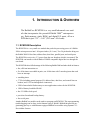
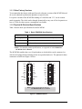
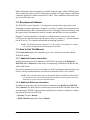
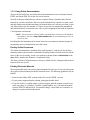
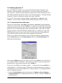
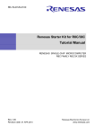
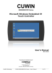
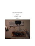
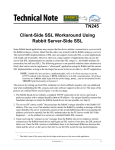
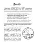
RabbitCore RCM2300
C-Programmable Module
Getting Started Manual
019–0101 •
040515–D
RabbitCore RCM2300 Getting Started Manual
Part Number 019-0101 • 040515–C • Printed in U.S.A.
© 2001–2004 Z-World, Inc. • All rights reserved.
Z-World reserves the right to make changes and
improvements to its products without providing notice.
Trademarks
Rabbit and Rabbit 2000 are registered trademarks of Rabbit Semiconductor.
RabbitCore is a trademark of Rabbit Semiconductor.
Dynamic C is a registered trademark of Z-World Inc.
Z-World, Inc.
Rabbit Semiconductor
2900 Spafford Street
Davis, California 95616-6800
USA
2932 Spafford Street
Davis, California 95616-6800
USA
Telephone: (530) 757-3737
Fax: (530) 757-3792
Telephone: (530) 757-8400
Fax: (530) 757-8402
www.zworld.com
www.rabbitsemiconductor.com
RabbitCore RCM2300
TABLE OF CONTENTS
Chapter 1. Introduction & Overview
1
1.1 RCM2300 Description .....................................................................................................1
1.1.1 Other Factory Versions ................................................................................................................2
1.1.2 Physical & Electrical Specifications ............................................................................................2
1.2 Development Software .....................................................................................................3
1.3 How to Use This Manual ..................................................................................................3
1.3.1 Additional Product Information ...................................................................................................3
1.3.2 Additional Reference Information ...............................................................................................3
1.3.3 Using Online Documentation .......................................................................................................4
Chapter 2. Hardware Setup
5
2.1 Development Kit Contents ................................................................................................5
2.2 Prototyping Board ...........................................................................................................6
2.2.1 Prototyping Board Features .........................................................................................................7
2.2.2 Prototyping Board Expansion ......................................................................................................8
2.3 Development Hardware Connections ..................................................................................9
2.3.1 Attach RCM2300 to Prototyping Board ......................................................................................9
2.3.2 Connect Programming Cable .....................................................................................................10
2.3.3 Connect Power Supply ...............................................................................................................11
2.4 Where Do I Go From Here? ............................................................................................12
2.4.1 Technical Support ......................................................................................................................12
Chapter 3. Software Installation & Overview
13
3.1 An Overview of Dynamic C ............................................................................................13
3.2 System Requirements ....................................................................................................14
3.2.1 Hardware Requirements .............................................................................................................14
3.3 Installing Dynamic C .....................................................................................................15
3.3.1 Program and Documentation File Location ...............................................................................15
3.3.2 Installation Type ........................................................................................................................16
3.3.3 Select COM Port ........................................................................................................................17
3.3.4 Desktop Icons .............................................................................................................................17
3.4 Starting Dynamic C .......................................................................................................18
3.4.1 Communication Error Messages ................................................................................................18
3.5 Sample Programs ..........................................................................................................19
Notice to Users
21
Index
23
Schematics
25
Getting Started Manual
RabbitCore RCM2300
1. INTRODUCTION & OVERVIEW
The RabbitCore RCM2300 is a very small advanced core module that incorporates the powerful Rabbit 2000™ microprocessor, flash memory, static RAM, and digital I/O ports, all on a
PCB that is just 1.15" × 1.60" (29.2 mm × 40.6 mm).
1.1 RCM2300 Description
The RCM2300 is a very small core module that packs the processing power of a Rabbit
2000™ microprocessor into 1.84 square inches (11.9 cm2). Two 26-pin headers bring out
the Rabbit 2000 I/O bus lines, address lines, data lines, parallel ports, and serial ports.
The RCM2300 receives its +5 V power from the user board on which it is mounted. The
RCM2300 can interface with all kinds of CMOS-compatible digital devices through the
user board.
The RCM2300 takes full advantage of the following Rabbit 2000 and other built-in features:
• fast, efficient instruction set.
• five 8-bit timers cascadable in pairs, one 10-bit timer with 2 match registers that each
have an interrupt.
• watchdog timer.
• 57 I/O (including general-purpose I/O, address lines, data lines, and control lines on
headers, and 11 I/O on through-hole connectors).
• 256K of nonvolatile flash memory to store applications written for the RCM2300.
• 128K of battery-backable SRAM.
• fast 22.1 MHz clock speed.
• provision for onboard backup battery.
• four serial ports.
Another RabbitCore module can be used to reprogram an RCM2300. This reprogramming
(and debugging) can be done via the Internet using Z-World’s RabbitLink network programming gateway or with Ethernet-equipped RabbitCore modules using Dynamic C’s
DeviceMate features.
Getting Started Manual
1
1.1.1 Other Factory Versions
To accommodate developers with specific needs, alternate versions of the RCM2300 module can be obtained in production quantities on special order.
Low-power variants of the RCM2300 running at 3.686 MHz and 3.3 V can be custom
made in quantity. The clock can be changed dynamically to any one of five frequencies as
low as 32 kHz to reduce power consumption even further.
1.1.2 Physical & Electrical Specifications
Table 1 lists the basic specifications for the RCM2300.
Table 1. Basic RCM2300 Specifications
Specification
Data
Power Supply
4.75 – 5.25 VDC (108 mA at 22.1 MHz clock speed)
Size
1.15" × 1.60" × 0.55" (29 mm × 41 mm × 14 mm)
Environmental
–40°C to 85°C, 5–95% humidity, noncondensing
NOTE: For complete product specifications, see Appendix A in the RabbitCore
RCM2300 User’s Manual.
The RCM2300 modules have two 26-pin headers to which cables can be connected, or
which can be plugged into matching sockets on a production device. The pinouts for these
connectors are shown in Figure 1 below.
J4
GND
PC0
PC2
PC6
PE2
PD4
/IORD
PE0
SMODE1
PE4
STATUS
A3
A1
J5
VCC
PC1
PC3
PC7
PD3
PD5
/IOWR
PE1
SMODE0
PE5
PE7
A2
A0
PA0
PA2
PA4
PA6
/RES
PB2
PB4
PB7
D6
D4
D2
D0
VCC
PA1
PA3
PA5
PA7
PB0
PB3
PB5
D7
D5
D3
D1
VBAT
GND
Note: These pinouts are as seen on
the Bottom Side of the module.
Figure 1. RCM2300 Pinout
2
RabbitCore RCM2300
Fifteen additional connection points are available along one edge of the RCM2300 board.
These connection points are 0.030" diameter holes spaced 0.05" apart. Nineteen additional
connection points are available at locations J2 and J3. These additional connection points
are reserved for future use.
1.2 Development Software
The RCM2300 uses the Dynamic C development environment for rapid creation and
debugging of runtime applications. Dynamic C provides a complete development environment with integrated editor, compiler and source-level debugger. It interfaces directly with
the target system, eliminating the need for complex and unreliable in-circuit emulators.
Dynamic C must be installed on a Windows workstation with at least one free serial
(COM) port for communication with the target system. See Chapter 3, “Software Installation & Overview,” for complete information on installing Dynamic C.
NOTE: The RCM2300 requires Dynamic C v7.04 or later for development. A compatible version is included on the Development Kit CD-ROM.
1.3 How to Use This Manual
This Getting Started manual is intended to give users a quick but solid start with the
RCM2300 module.
1.3.1 Additional Product Information
Detailed information about the RabbitCore RCM2300 is provided in the RabbitCore
RCM2300 User’s Manual provided on the accompanying CD-ROM in both HTML and
Adobe PDF format.
Some advanced users may choose to skip the rest of this introductory manual and proceed
directly with the detailed hardware and software information in the User’s manual.
NOTE: We recommend that anyone not thoroughly familiar with Rabbit Semiconductor
or Z-World products at least read through the rest of this manual to gain the necessary
familiarity to use the more advanced information.
1.3.2 Additional Reference Information
In addition to the product-specific information contained in the RabbitCore RCM2300
User’s Manual, two other reference manuals are provided in HTML and PDF form on the
accompanying CD-ROM. Advanced users will find these references valuable in developing systems based on the RCM2300.
• Dynamic C User’s Manual
• Rabbit 2000 Microprocessor User’s Manual
Getting Started Manual
3
1.3.3 Using Online Documentation
We provide the bulk of our user and reference documentation in two electronic formats,
HTML and Adobe PDF. We do this for several reasons.
We believe that providing all users with our complete library of product and reference
manuals is a useful convenience. However, printed manuals are expensive to print, stock
and ship. Rather than include and charge for manuals that every user may not want, or provide only product-specific manuals, we choose to provide our complete documentation
and reference library in electronic form with every development kit and with our Dynamic
C development environment.
NOTE: The most current version of Adobe Acrobat Reader can always be downloaded
from Adobe’s web site at http://www.adobe.com. We recommend that you use version 4.0 or later.
Providing this documentation in electronic form saves an enormous amount of paper by
not printing copies of manuals that users don’t need.
Finding Online Documents
The online documentation is installed along with Dynamic C, and an icon for the documentation menu is placed on the workstation’s desktop. Double-click this icon to reach the
menu. If the icon is missing, create a new desktop icon that points to default.htm in the
docs folder, found in the Dynamic C installation folder.
The latest versions of all documents are always available for free, unregistered download
from our Web site as well.
Printing Electronic Manuals
We recognize that many users prefer printed manuals for some uses. Users can easily print
all or parts of those manuals provided in electronic form. The following guidelines may be
helpful:
• Print from the Adobe PDF versions of the files, not the HTML versions.
• If your printer supports duplex printing, print pages double-sided.
• If you do not have a suitable printer or do not want to print the manual yourself, most
retail copy shops (e.g. Kinkos, CopyMax, AlphaGraphics, etc.) will print the manual
from the PDF file and bind it for a reasonable charge—about what we would have to
charge for a printed and bound manual.
4
RabbitCore RCM2300
2. HARDWARE SETUP
This chapter describes the RCM2300 hardware in more detail,
and explains how to set up and use the accompanying Prototyping Board.
NOTE: This chapter (and this manual) assume that you have the RabbitCore RCM2300
Development Kit. If you purchased an RCM2300 module by itself, you will have to
adapt the information in this chapter and elsewhere to your test and development setup.
2.1 Development Kit Contents
The RCM2300 Development Kit contains the following items:
• RCM2300 module with 256K flash memory and 128K SRAM.
• RCM2200/RCM2300 Prototyping Board.
• Wall transformer power supply, 12 V DC, 500 mA. The power supply is included only
with Development Kits sold for the North American market. Overseas users should use
a locally available power supply capable of delivering 7.5 V to 25 V DC to the Prototyping Board.
• Programming cable with integrated level-matching circuitry.
• Dynamic C CD-ROM, with complete product documentation on CD.
• This Getting Started manual.
• Rabbit 2000 Processor Easy Reference poster.
• Registration card.
Getting Started Manual
5
2.2 Prototyping Board
The Prototyping Board included in the Development Kit makes it easy to connect an
RCM2300 to a power supply for development. It also provides some basic I/O peripherals
(switches and LEDs), as well as a prototyping area for more advanced hardware development.
The Prototyping Board can be used without modification for the most basic level of evaluation and development.
As you progress to more sophisticated experimentation and hardware development, modifications and additions can be made to the board without modifying or damaging the RabbitCore module itself.
The Prototyping Board is shown in Figure 2, with its main features identified.
RCM2200/RCM2300
User
Reset
RCM2200/RCM2300
Slave Module
Power
Switch Switches
Master Module
Voltage
Connectors
Input
Connectors
Regulator
Power
User
LED
LEDs
Through-Hole
Prototyping Area
Master Module
Extension Headers
Slave Module
Extension Headers
Battery
CAUTION
RS-232
Signal
Header
Battery
SMT Prototyping
Area
Vcc and GND
Buses
Figure 2. RCM2200/RCM2300 Prototyping Board
6
RabbitCore RCM2300
2.2.1 Prototyping Board Features
• Power Connection—A 3-pin header is provided at J5 for the power supply connection. Note that both outer pins are connected to ground and the center pin is connected
to the raw V+ input. The cable from the wall transformer provided with the North
American version of the Development Kit ends in a connector that may be connected in
either orientation.
Users providing their own power supply should ensure that it delivers 7.5–25 V DC at
not less than 500 mA. The voltage regulator will get warm in use. (Lower supply voltages will reduce thermal dissipation from the device.)
• Regulated Power Supply—The raw DC voltage provided to the POWER header at J5
is routed to a 5 V linear voltage regulator, which provides stable power to the
RCM2300 and the Prototyping Board. A Shottky diode protects the power supply
against damage from reversed raw power connections.
• Power LED—The power LED lights whenever power is connected to the Prototyping
Board.
• Reset Switch—A momentary-contact, normally open switch is connected directly to the
master RCM2300’s /RES pin. Pressing the switch forces a hardware reset of the system.
• I/O Switches and LEDs—Two momentary-contact, normally open switches are connected to the PB2 and PB3 pins of the master RCM2300, and may be read as inputs by
sample applications.
Two LEDs are connected to the PE1 and PE7 pins of the master RCM2300, and may be
driven as output indicators by sample applications.
The LEDs and switches are connected through JP1, which has traces shorting adjacent
pads together. These traces may be cut to disconnect the LEDs, and an 8-pin header
may then be soldered into JP1 to permit their selective reconnection with jumpers. See
Figure 3 for details.
• Expansion Areas—The Prototyping Board is provided with several unpopulated areas
for expansion of I/O and interfacing capabilities. See the next section for details.
• Prototyping Area—A generous prototyping area has been provided for the installation
of through-hole components. Vcc (5 V DC) and Ground buses run around the edge of
this area. An area for surface-mount devices is provided to the right of the through-hole
area. Note that there are SMT device pads on both top and bottom of the Prototyping
Board. Each SMT pad is connected to a hole designed to accept a 30 AWG solid wire,
which must be soldered once it is in the hole.
• Slave Module Connectors—A second set of connectors is pre-wired to permit installation of a second, slave RCM2200 or RCM2300.
Getting Started Manual
7
2.2.2 Prototyping Board Expansion
The Prototyping Board comes with several unpopulated areas, which may be filled with
components to suit the user’s development needs. After you have experimented with the
sample programs in Section 3.5, you may wish to expand the Prototyping Board’s capabilities for further experimentation and development. Refer to the Prototyping Board schematic (090–0122) for details as necessary.
• Module Extension Headers—The complete pin set of both the master and slave modules is duplicated at these two sets of headers. Developers can solder wires directly into
the appropriate holes, or, for more flexible development, 0.1" pitch 26-pin header strips
can be soldered into place. See Figure 1 for the header pinouts.
• RS-232—Two 2-wire or one 5-wire RS-232 serial port can be added to the Prototyping
Board by installing an RS-232 driver IC and four capacitors. The Maxim MAX232CPE
driver chip or a similar device is recommended for U2. Refer to the Prototyping Board
schematic for additional details.
A 10-pin 0.1-inch spacing header strip can be installed at J6 to permit connection of a
ribbon cable leading to a standard DE-9 serial connector.
All RS-232 port components mount to the top side of the Prototyping Board below and
to the left of the MASTER module position.
NOTE: The RS-232 chip, capacitors and header strip are available from electronics distributors such as Digi-Key.
• Prototyping Board Component Header—Four I/O pins from the RCM2300 module
are hard-wired to the Prototyping Board LEDs and switches through JP1 on the underside of the Prototyping Board.
To disconnect these devices and permit
the pins to be used for other purposes, cut
the traces between the pin rows of JP1.
Use a knife or similar tool to cut or break
the traces crossing JP1 in the area
between the silk-screened arrows, as
indicated in Figure 3.
Use jumpers across the positions on
JP1 if you need to reconnect any of the
devices later on.
8
JP1
DS2 DS3 S2
S3
Cut
Cut
PE1 PE7 PB2 PB3
Figure 3. Prototyping Board Header JP1
(located on BOTTOM SIDE of board)
RabbitCore RCM2300
2.3 Development Hardware Connections
There are three steps to connecting the Prototyping Board for use with Dynamic C and the
sample programs:
1. Attach the RCM2300 to the Prototyping Board.
2. Connect the programming cable between the RCM2300 and the PC.
3. Connect the power supply to the Prototyping Board.
2.3.1 Attach RCM2300 to Prototyping Board
Y3
R29
VCC
VBAT
+
C24
R18
R22
D2
R21
Q4
Q3
R26
R19
Q2
C12
C15
R15
G
R34
R23
C10
R2
C11 U1
R13
J1
R1
JP2
JP1
R17
R37
C8
Q5
R20
C13
R36
C27
R8
C4
Y1
C3
RCM2300
U6
R7
R38
D1
U2
C9
C23
C14
BEN
J3 WD
J2
VCC
D3
RT1
R41
PE6
PD2
PD0
PD1
PD7
PE3
PD6
GND
R39
GND
VCC
Turn the RCM2300 module so that the header pins and the mounting hole of the RCM2300
line up with the sockets and mounting hole on the Prototyping Board as shown in Figure 4.
Align the module headers J4 and J5 into sockets J1 and J2 on the Prototyping Board.
Battery
CAUTION
Line up the
mounting holes
Figure 4. Install the RCM2300 on the Prototyping Board
Getting Started Manual
9
Although you can install a single module into either the MASTER or the SLAVE position
on the Prototyping Board, all the Prototyping Board features (switches, LEDs, serial port
drivers, etc.) are connected to the MASTER position. We recommend you install a single
module in the MASTER position.
NOTE: It is important that you line up the pins on headers J4 and J5 of the RCM2300
exactly with the corresponding pins of headers J1 and J2 on the Prototyping Board. The
header pins may become bent or damaged if the pin alignment is offset, and the module
will not work. Permanent electrical damage to the module may also result if a misaligned module is powered up.
Press the module’s pins firmly into the Prototyping Board headers.
2.3.2 Connect Programming Cable
The programming cable connects the RCM2300 module to the PC workstation running
Dynamic C to permit download of programs and monitoring for debugging.
Connect the 10-pin connector of the programming cable labeled PROG to header J1 on
the RabbitCore RCM2300 module as shown in Figure 5. Be sure to orient the marked
(usually red) edge of the cable towards pin 1 of the connector. (Do not use the DIAG connector, which is used for a normal serial connection.)
Connect the other end of the programming cable to a COM port on
your PC. Make a note of the port to
which you connect the cable, as
Dynamic C needs to have this parameter configured when it is installed.
NOTE: COM 1 is the default
port used by Dynamic C.
Figure 5. Connect Programming Cable
to RCM2300
10
RabbitCore RCM2300
2.3.3 Connect Power Supply
When the above connections have been made, you can connect power to the RabbitCore
Prototyping Board.
Hook the connector from the wall transformer to header J5 on the Prototyping Board as
shown in Figure 6. The connector may be attached either way as long as it is not offset to
one side.
AC Adapter
Prototyping
Reset Board
Switch
VBAT
+
Y3
R29
VCC
R21
Q4
R19
Q3
R17
R15
Q2
C11 U1
Q5
R20
C13
JP2
JP1
G
R34
R23
C10
R2
R1
C8
R13
PROG
C12
C15
R26
R37
J1
C24
R18
R22
D2
R36
C27
R8
C4
Y1
C3
U6
R7
R38
D1
U2
C9
C23
C14
BEN
J3 WD
J2
VCC
D3
RT1
R41
PE6
PD2
PD7
PE3
PD6
PD0
PD1
GND
R39
GND
VCC
RCM2300
DIAG
Figure 6. Power Supply Connections
Plug in the wall transformer. The power LED (DS1) on the Prototyping Board should light
up. The RCM2300 and the Prototyping Board are now ready to be used.
NOTE: A RESET button is provided on the Prototyping Board to allow hardware reset
without disconnecting power.
To power down the Prototyping Board, unplug the power connector from J5. You should
disconnect power before making any circuit adjustments in the prototyping area, changing
any connections to the board, or removing the RCM2300 from the board.
Getting Started Manual
11
2.4 Where Do I Go From Here?
We recommend that you proceed to the next chapter and install Dynamic C (if you do not
already have it installed), then run the first sample program to verify that the RCM2300
and the Prototyping Board are set up and functioning correctly.
If everything appears to be working, we recommend the following sequence of action:
1. Run all of the sample programs described in Section 3.5 to get a basic familiarity with
Dynamic C and the RCM2300’s capabilities.
2. For further development, refer to the RabbitCore RCM2300 User’s Manual for details
of the RCM2300’s hardware and software components.
A documentation icon should have been installed on your workstation’s desktop; click
on it to reach the documentation menu. You can create a new desktop icon that points to
default.htm in the docs folder in the Dynamic C installation folder.
3. For advanced development topics, refer to the Dynamic C User’s Manual, also in the
online documentation set.
2.4.1 Technical Support
NOTE: If you purchased your RCM2300 through a distributor or through a Z-World or
Rabbit Semiconductor partner, contact the distributor or Z-World partner first for technical support.
If there are any problems at this point:
• Check the Z-World/Rabbit Semiconductor Technical Bulletin Board at
www.zworld.com/support/.
• Use the Technical Support e-mail form at www.zworld.com/support/.
12
RabbitCore RCM2300
3. SOFTWARE INSTALLATION & OVERVIEW
To develop and debug programs for the RCM2300 (and for all
other Z-World and Rabbit Semiconductor hardware), you must
install and use Dynamic C. This chapter takes you through the
installation of Dynamic C, and then provides a tour of its major
features with respect to the RabbitCore RCM2300 module.
3.1 An Overview of Dynamic C
Dynamic C integrates the following development functions into one program:
• Editing
• Compiling
• Linking
• Loading
• In-Circuit Debugging
In fact, compiling, linking and loading are one function. Dynamic C does not use an InCircuit Emulator; programs being developed are downloaded to and executed from the
“target” system via an enhanced serial-port connection. Program development and debugging take place seamlessly across this connection, greatly speeding system development.
Other features of Dynamic C include:
• Dynamic C has an easy-to-use built-in text editor. Programs can be executed and
debugged interactively at the source-code or machine-code level. Pull-down menus and
keyboard shortcuts for most commands make Dynamic C easy to use.
• Dynamic C also supports assembly language programming. It is not necessary to leave
C or the development system to write assembly language code. C and assembly language may be mixed together.
• Debugging under Dynamic C includes the ability to use printf commands, watch
expressions, breakpoints and other advanced debugging features. Watch expressions
can be used to compute C expressions involving the target’s program variables or functions. Watch expressions can be evaluated while stopped at a breakpoint or while the
target is running its program.
Getting Started Manual
13
• Dynamic C provides extensions to the C language (such as shared and protected variables, costatements and cofunctions) that support real-world embedded system development. Interrupt service routines may be written in C. Dynamic C supports
cooperative and preemptive multitasking.
• Dynamic C comes with many function libraries, all in source code. These libraries support real-time programming, machine level I/O, and provide standard string and math
functions.
• Dynamic C compiles directly to memory. Functions and libraries are compiled and
linked and downloaded on-the-fly. On a fast PC, Dynamic C can load 30,000 bytes of
code in 5 seconds at a baud rate of 115,200 bps.
3.2 System Requirements
To install and run Dynamic C, your system must be running one of the following operating
systems:
• Windows 95
• Windows 98
• Windows NT
• Windows Me
• Windows 2000
• Windows XP
3.2.1 Hardware Requirements
The PC on which you install Dynamic C for development of RCM2300-based systems
should have the following hardware:
• A Pentium or later microprocessor
• 32 MB of RAM
• At least 50 MB of free hard drive space
• At least one free COM (serial) port for communication with the target systems
• A CD-ROM drive (for software installation)
14
RabbitCore RCM2300
3.3 Installing Dynamic C
Insert the Dynamic C CD-ROM in the drive on your PC. If autorun is enabled, the CD
installation will begin automatically.
If autorun is disabled or the installation otherwise does not start, use the Windows
Start > Run menu or Windows Explorer to launch SETUP.EXE from the root folder of the
CD-ROM.
The installation program will guide you through the installation process. Most steps of the
process are self-explanatory and not covered in this section. Selected steps that may be
confusing to some users are outlined below. (Some of the installation utility screens may
vary slightly from those shown.)
3.3.1 Program and Documentation File Location
Dynamic C’s application, library and documentation files can be installed in any convenient location on your workstation’s hard drives.
The default location, as shown in the example above, is in a folder named for the version
of Dynamic C, placed in the root folder of the C: drive. If this location is not suitable, enter
a different root path before clicking Next >. Files are placed in the specified folder, so do
not set this location to a drive’s root directory.
Getting Started Manual
15
3.3.2 Installation Type
Dynamic C has two components that can be installed together or separately. One component is Dynamic C itself, with the development environment, support files and libraries.
The other component is the documentation library in HTML and PDF formats, which may
be left uninstalled to save hard drive space or installed elsewhere (on a separate or network drive, for example).
The installation type is selected in the installation menu shown above. The options are:
• Typical Installation — Both Dynamic C and the documentation library will be
installed in the specified folder (default).
• Compact Installation — Only Dynamic C will be installed.
• Custom Installation — You will be allowed to choose which components are
installed. This choice is useful to install or reinstall just the documentation.
16
RabbitCore RCM2300
3.3.3 Select COM Port
Dynamic C uses a COM (serial) port to communicate with the target development system.
The installation allows you to choose the COM port that will be used.
The default selection, as shown in the example above, is COM1. You may select any available port for Dynamic C’s use. If you are not certain which port is available, select COM1.
This selection can be changed later within Dynamic C.
NOTE: The installation utility does not check the selected COM port in any way. Specifying a port in use by another device (mouse, modem, etc.) may cause temporary problems when Dynamic C is started.
3.3.4 Desktop Icons
Once your installation is complete, you will have up to three icons on your PC desktop, as
shown below.
One icon is for Dynamic C, one opens the documentation menu, and the third is for the
Rabbit Field Utility, a tool used to download precompiled software to a target system.
Getting Started Manual
17
3.4 Starting Dynamic C
Once the RabbitCore module is set up and connected as described in Chapter 2 and
Dynamic C has been installed, start Dynamic C by double-clicking on the Dynamic C
icon. Dynamic C should start, then look for the target system on the COM port you specified during installation (by default, COM1). Once detected, Dynamic C should go through
a sequence of steps to cold-boot the module and compile the BIOS.
If you receive the message beginning "BIOS successfully compiled and
loaded…" you are ready to continue with the sample programs in the next section.
3.4.1 Communication Error Messages
If you receive the message "No Rabbit Processor Detected" the programming
cable may be connected to a different COM port, a connection may be faulty, or the target
system may not be powered up. First, check to see that the power LED on the Prototyping
Board is lit. If it is, check both ends of the programming cable to ensure that it is firmly
plugged into the PC and the RCM2300’s programming port, with the pin-1 edge of the
cable matched to the pin-1 mark on the board. If you are using the Prototyping Board,
ensure that the module is firmly and correctly installed in its connectors.
If there are no faults with the hardware, select a different COM port within Dynamic C.
From the Options menu, select Project Options, then select Communications. The
dialog shown should appear.
Select another COM port from the list, then click OK. Press <Ctrl-Y> to force Dynamic C
to recompile the BIOS. If Dynamic C still reports it is unable to locate the target system,
repeat the above steps until you locate the active COM port.
If you receive the “BIOS successfully compiled …” message after pressing <Ctrl-Y> or
starting Dynamic C, and this message is followed by a communications error message, it
is possible that your PC cannot handle the 115,200 bps baud rate. Try changing the baud
rate to 57,600 bps as follows.
• Locate the Serial Options dialog in the Dynamic C Options > Project Options >
Communications menu. Change the baud rate to 57,600 bps. Then press <Ctrl-Y> or
restart Dynamic C.
18
RabbitCore RCM2300
3.5 Sample Programs
To help familiarize you with the RCM2300 modules, Dynamic C includes several sample
programs. Loading, executing and studying these programs will give you a solid hands-on
overview of the RCM2300’s capabilities, as well as a quick start with Dynamic C as an
application development tool.
NOTE: The sample programs assume that you have at least an elementary grasp of ANSI
C. If you do not, see the introductory pages of the Dynamic C User’s Manual for a suggested reading list.
Of the many sample programs included with Dynamic C, several are specific to the
RCM2200 module. These programs will be found in the Samples\RCM2300 folder.
We suggest that you examine the following three of these sample programs to get a complete tour of the capabilities of the RabbitCore RCM2300 modules. They form a “learning
arc” from basic to advanced I/O control.
• FLASHLED.C—Master RCM2300 repeatedly flashes LED DS3 on the Prototyping
Board.
• FLASHLEDS.C—Master RCM2300 repeatedly flashes LEDs DS2 and DS3 on the Prototyping Board.
• TOGGLELED.C—Master RCM2300 flashes LED DS2 on the Prototyping Board and
toggles LED DS3 on/off in response to pressing S3.
Each of these programs is fully commented within the source code. Refer to these comments for the details of how each program works.
Once you have loaded and executed these three programs and have an understanding of
how Dynamic C and the RCM2300 modules interact, you can move on and try the other
sample programs, or begin building your own.
Getting Started Manual
19
20
RabbitCore RCM2300
NOTICE TO USERS
Z-WORLD PRODUCTS ARE NOT AUTHORIZED FOR USE AS CRITICAL COMPONENTS IN LIFESUPPORT DEVICES OR SYSTEMS UNLESS A SPECIFIC WRITTEN AGREEMENT REGARDING
SUCH INTENDED USE IS ENTERED INTO BETWEEN THE CUSTOMER AND Z-WORLD PRIOR
TO USE. Life-support devices or systems are devices or systems intended for surgical implantation into the
body or to sustain life, and whose failure to perform, when properly used in accordance with instructions for
use provided in the labeling and user’s manual, can be reasonably expected to result in significant injury.
No complex software or hardware system is perfect. Bugs are always present in a system of any size. In
order to prevent danger to life or property, it is the responsibility of the system designer to incorporate
redundant protective mechanisms appropriate to the risk involved.
All Z-World products are 100 percent functionally tested. Additional testing may include visual quality control inspections or mechanical defects analyzer inspections. Specifications are based on characterization of
tested sample units rather than testing over temperature and voltage of each unit. Z-World products may
qualify components to operate within a range of parameters that is different from the manufacturer’s recommended range. This strategy is believed to be more economical and effective. Additional testing or burn-in
of an individual unit is available by special arrangement.
Getting Started
21
22
RabbitCore RCM2300
INDEX
A
F
additional information
online documentation .......... 4
references ............................ 3
features
Prototyping Board ........... 6, 7
RCM2300 ............................ 1
C
H
C language ...................... 13, 14
hardware connections ............. 9
install RCM2300 on Prototyping Board ........................ 9
power supply ..................... 11
programming cable ........... 10
hardware reset ....................... 11
D
description ............................... 1
Development Kit ..................... 5
Dynamic C .................. 3, 13, 14
assembly language ............ 13
debugger ............................ 13
debugging .......................... 13
desktop icons ..................... 17
editor ................................. 13
features .............................. 13
handling communication error
messages ....................... 18
hardware requirements ...... 14
installing ...................... 15, 17
interrupt service routines .. 14
sample programs ............... 19
starting .............................. 18
watch expressions ............. 13
Getting Started Manual
programming cable
RCM2300 connections ......10
Prototyping Board ....................6
expansion area .....................8
features .............................6, 7
mounting RCM2300 ............9
optional header JP1 ..............8
R
RCM2300
mounting on Prototyping
Board ...............................9
reset ........................................11
J
S
JP1
Prototyping Board ............... 8
software
sample programs ................19
FLASHLED.C ...............19
FLASHLEDS.C .............19
TOGGLELED.C ............19
specifications
physical and electrical ..........2
M
models
factory versions ................... 2
P
pinout
RCM2300 ............................ 2
power supply
connections ....................... 11
T
technical support ....................12
23
24
RabbitCore RCM2300
SCHEMATICS
090-0119 RCM2300 Schematic
www.rabbitsemiconductor.com/documentation/schemat/090-0119.pdf
090-0122 RCM2200/RCM2300 Prototyping Board Schematic
www.rabbitsemiconductor.com/documentation/schemat/090-0122.pdf
090-0128 Programming Cable Schematic
www.rabbitsemiconductor.com/documentation/schemat/090-0128.pdf
The schematics included with the printed manual were the latest revisions available at the
time the manual was last revised. The online versions of the manual contain links to the
latest revised schematic on the Web site. You may also use the URL information provided
above to access the latest schematics directly.
Getting Started Manual
25
Mouser Electronics
Authorized Distributor
Click to View Pricing, Inventory, Delivery & Lifecycle Information:
Rabbit Semiconductor:
101-0480