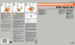
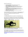
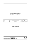
1
Model 1461
Single Channel
Motion Detector
Installation and Operating Instructions
The 1461 is an analog device for the detection of motion in the field of view of a TV camera. It is intended as an aid to personnel
engaged in monitoring a TV display and is not intended as a primary alarm input device.
The software/firmware furnished with this equipment is confidential to and is copyrighted by AMERICAN DYNAMICS. It is
not to be copied or disclosed in any manner without the express written consent of AMERICAN DYNAMICS. The
software/firmware is furnished to the purchaser under a license for use on a single system.
Note: Information furnished by AMERICAN DYNAMICS is believed to be accurate and reliable. However, no responsibility is
assumed by AMERICAN DYNAMICS. for its use; nor for any infringements of other rights of third parties which may result
from its use. No license is granted by implications or otherwise under any patent or patent rights of AMERICAN DYNAMICS.
= =- AMERXfAN
-=L-‘DYNRM/CS
The installation of this product should be made by qualified
service personnel and should conform to all local codes.
symbol, within an equilateral triangle, is
intended to alert the user to the presence of
product’s enclosure that may he of sufficient magnitude to constitute a risk of electric shock to persons.
CAUTION: To reduce the risk of electric
shock, do not remove covers (or back).
No user-serviceable parts inside.
Refer servicing to qualified service personnel
WARNING
To reduce the risk of fire or shock hazard, do
not expose this product to rain or moisture.
Warning: This product generatesuses, and can radiate
radio frequency energy and if not installed and used in accordance with the instruction manual, may cause interference to
radio communications. It has been tested and found to comply with the limits for a Class A computing device pursuant
to Part 15 of FCC Rules, which are designed to provide reasonable protection against such interference whrn operated in
a commercial environment. Operation of this product in a
residential area is likely to cause interference in which case
the user at his own expense will be required to take whatever measures may be required to correct the interference
t
l
n
The exclamation point within an equilateral
triangle is intended to alert the user to the
presence of important operating and maintenance (servicing) instructions in the
literature accompanying the product.
UNPACKING AND INSPECTION
Unpack carefully. This is an electronic product and
should be handled as such. Compare the items
received with the packing list with your order.
Be sure to save:
1. The shipping cartons and insert pieces. They are the
safest material in which to make future shipments
of the product.
2. The IMPORTANT SAFEGUARDS sheet.
3. These Installation and Operating Instructions.
MAINTENANCE
User maintenance of this unit is limited to external
cleaning and inspection. For specific recommendations refer to the IMPORTANT SAFEGUARDS sheet
packaged with this product.
INSTALLATION AND SERVICE
If you require information during installation of this
product or if service seems necessary, contact the
Sensormatic Video Products Division at (619) 6422400. You must obtain a Return Authorization
Number and shipping instructions before returning any
product for service.
Do not attempt to service this product yourself.
Opening or removing covers may expose you to dangerous voltages or other hazards. Refer all servicing to
qualified personnel.
QA30lD
Table of Contents
Product Description . . . . . . . . . . . . . . . . . . . . . . . . . . . . . . . . . . . . . . . . . . . . . . . . . . . . . . . . . . . . . . . 1
Features . . . . . . . . . . . . . . . . . . . . . . . . . . . . . . . . . . . . . . . . . . . . . . . . . . . . . . . . . . . . . . . . . . . . . . . . . . . . . . . . . .
1
Installation . . . . . . . . . . . . . . . . . . . . . . . . . . . . . . . . . . . . . . . . . . . . . . . . . . . . . . . . . . . . . . . . . . . . . . . . . . . . . .
1
Connections . . . . . . . . . . . . . . . . . . . . . . . . . . . . . . . . . . . . . . . . . . . . . . . . . . . . . . . . . . . . . . . . . . . . . . . . . . . .
2
Operation................................................................................
Operating Controls ......................................................
Setup ............................................................................
Normal Operation .......................................................
3
3
4
.4
Appendix
System Considerations ................................... ............ A
Typical System Connections ...................................... .C
DESCRIPTION
DISPLAY
BYPASS AUTO RESET
Figure 1 - 1461 Front Panel
PRODUCT DESCRIPTION
INSTALLATION
The 1461 is an analog device for the detection of motion in the
field of view of a TV camera. It is intended as an aid to
personnel engaged in monitoring a TV display and is not
intended as a primary alarm input device.
Systems involving video motion detectors must use the best
possible connection and grounding practices. Poor wiring not
only causes poor pictures, but could affect the alert function.
Camera and lens selection, camera location, scene lighting, and
mounting are also significant factors in achieving optimum
performance. These factors are covered in more detail in the
Appendix, System Considerations.
Only standard video from a camera is required. No external
sync drives are necessary. The video input is passively looped
to the output to allow the motion detector to be turned off with
no loss of video.
Mounting
The 1461 switcher is supplied as a desk-top unit. Place the
unit in a position convenient for the operator, usually adjacent
to the monitor to be viewed. For rack mounting, 2117 Series
rack-mount kits are available. The 1461 is a quarter-rack unit.
Up to four quarter-rack units such as a 1461 or a 1404A
Sequential Switcher may be mounted in a single 19” by 1 314”
rack. One or two may be mounted with half rack units such as
the 1440B Date/Time Generator.
The successful operation of video motion detectors depends on
many factors. The section on SYSTEM CONSIDERATIONS
in the Appendix should be reviewed before finalizing a system.
.
FEATURES
* MULTIPLE ALERT ACTION
* ADJUSTABLE DETECTION AREA
* ADJUSTABLE SENSITIVITY
IF YOU ENCOUNTER ANY PROBLEMS
OPERATING THIS UNIT, OR NEED TECHNICAL
ASSISTANCE, CALL:
* AUTO-COMPENSATION FOR SLOW LIGHT LEVEL
CHANGES
Sensormatic Video Products Division
6795 Flanders Drive
San Diego, CA 92121
* MANUAL OR AUTOMATIC RESET
* FRONT PANEL CONTROL
Tel: 619-642-2400
Fax: 619-642-2440
1
CONNECTIONS
12ov
60HZ
CONTROL
0
Figure 2 - 1461 Rear Panel
CONNECTIONS
Auxiliary Start Relay Connections
Video Input
The 5-pin CONTROL connector is also used to access a
normally open, SPST relay which can be used to activate a
VCR or other devices during an alert. The relay contacts
provide a closure between pins 3 and 4 when an alert condition
occurs. CAUTION: DO NOT USE THIS RELAY TO
SWITCH LINE VOLTAGES. The relay contact ratings are:
Connect a good grade of RG59/U video cable from the camera
to the VIDEO IN BNC Connector on the rear panel of the
1461. The 1461 has a passive loop-thru input. It does not
terminate the input in 75 ohms. The video input cable should
be terminated in 75 ohms at the end of the run.
Power:
Voltage:
Current:
Video Output
Connect a good grade of RG59AJ video cable from the VIDEO
PUT BNC connector on the rear panel of the 1461 to the video
input of the monitor or video switcher. This cable should be
terminated in 75 ohms, or if looped thru the monitor or
switcher, terminated at the end of the run.
.
Power
The model number and rated power are shown on the rear
panel of each unit. No power On/Off switch is provided. The
LED on the front panel is lit when power is applied to the unit.
Automatic Switcher Call-Up Connections
Connections to an external switcher are made at the
CONTROL connector on the rear panel of the 1461. Pin 2
provides a logic-level closure during an alert for remote call-up
of a switcher. A typical system connection for switcher call-up
is shown in the Appendix. The CONTROL connector pin
definitions are:
PIN1
PIN2
PIN3
PIN4
PIN5
10 VA max.
30 VDC or RMS max.
0.25 A DC or RMS max. (resistive load)
Model 1461 - 120 VAC, 60 Hz nominal. Insert the pendant
3-wire cord and plug into a mating power source.
Model 1461101 - 13.5 V DC (11 to 18 VDC). Attach the
leads extending from the rear panel to the power source. A
separate chassis ground terminal is also provided.
Ground
Switcher Logic Out
Auxiliary Relay Contact
Auxiliary Relay Contact
No Connection
Red Wire with Fuse Holder - (+) (hot) lead.
Black Wire - (-) (ground) lead.
Model 1461X - 230 VAC, 50/60 Hz nominal. Insert the
pendant 3-wire cord and plug into a mating power source.
Pin 1 is at the top of the connector, see Figure 2.
A mating 5-pin plug is provided. Note that this plug also
provides connections for the auxiliary start relay.
2
OPERATION
-@+ -@+ -@+
DISPLAY
BYPASS AUTO RESET
Figure 3 - 1461 Front Panel Controls
OPERATION
DISPLAY (+/-) - This two position toggle switch activates (+)
or deactivates (-) display of the two vertical bars indicating the
area of the picture in which motion is detected. (See Figure 4,
On-Screen Display, page 4.) It does not otherwise affect the
operation of the unit. The activated (+) position is normally
used unless public display of the area in which motion is being
detected is inadvisable.
Operating Controls
All operating controls are on the front panel of the 1461, as
shown in Figure 3.
Power ON LED - This LED is lit when power is applied to the
unit.
BYPASS (+/-) - This toggle switch activates (+) or deactivates
(-) the audio alert, the switcher call-up logic output and the
auxiliary start relay functions of the motion detector. It must
be in the activated (+) position when these functions are
desired. The visual ALERT LED’s are not affected by the
position of the BYPASS switch. In the deactivated (-)
position, when an alert occurs the LED’s flash, but the audio
signal, the switcher logic, and the relay are not active.
ALERT LEDs - These two LEDs flash alternately when
motion has been detected, until turned off by AUTO RESET or
by a manual RST (Reset).
RST (Reset) Button - After an alert has been indicated this
button restores the unit to the motion detection mode and stops
all alert signals. If the motion is still detected, the unit returns
immediately to the alert condition. The manual RST function
is available regardless of the AUTO RESET switch setting.
AUTO RESET (+/-) - This toggle switch activates (+) or
deactivates (-) the automatic reset of the motion detector.
When activated (+), an alert condition automatically is cleared
12 seconds after motion ceases. When deactivated (-), the
manual RST must be used to clear an alert condition.
SENS (Sensitivity) - This screwdriver control adjusts the
sensitivity of the active detection area. Clockwise rotation
increases sensitivity.
VERT (Vertical) P and S - These recessed screwdriver
controls adjust the vertical position and size of the rectangular
detection area. The P control adjusts the vertical position and
the S adjusts the vertical size of the area.
HORIZ (Horizontal) P and S - These recessed screwdriver
controls adjust the horizontal position and size of the
rectangular detection area. The P control adjusts the horizontal
position and the S adjusts the horizontal size of the area.
3
OPERATION
Setup
Normal Operation
1) Apply power to the motion detector and associated
cameras, switchers, and monitors. It is normally better to
have power to auxiliary equipment, such as VCR’s, off
during initial setup.
During normal operation the motion detector should be set
with all toggle switches in the active (+) position. This
displays the detection area enclosed by twin vertical bars, arms
the four action indicators, and enables the auto reset. It allows
the operator to look away from the monitor yet readily locate
the detection area on the screen. Motion alerts will activate all
alert functions. The unit will automatically reset to the
detection mode 12 seconds after the detected motion ceases. If
the operator wishes to turn the alert indicators off and reset
sooner, the manual reset button (RST) can be used.
2) If necessary, adjust the switcher to display the camera
video which is to be monitored by the motion detector.
3) Turn all three motion detector toggle switches to the
deactive (-) positions.
If the motion detector is used on a critical area during a noncritical time period, such as a doorway at quitting time, the
BYPASS switch may be set to the deactive (-) position. In this
mode the LED’s will flash, but the audio signal, the relay, and
the switcher logic will not activate.
4) Turn the DISPLAY switch to active (+). Note the twin
vertical bars, as shown in Figure 4, On-Screen Display.
These bars define the rectangular area of the picture within
which motion is detected. The size of this area may be
adjusted using using the front panel screwdriver controls
for vertical (VERT) and horizontal (HORIZ) position (P)
and size (S). Set the sensitive area to cover the region of
the picture within which motion is to be detected.
5) Turn the BYPASS switch to active (+). This activates the
four alert functions. Motion in the sensitive area causes:
- the visual ALERT LED’s to flash alternately,
- the audio beeper to sound,
- the auxiliary start relay contacts to close, and
- the switcher logic output to go active low.
6) Ensure that the AUTO RESET switch is in the deactive (-)
‘X position before proceeding with Step 7. This allows
sensitivity to be adjusted without the interference of an
automatic reset.
DETECTION AREA
7) Sensitivity; the most critical adjustment, is adjusted using
the screwdriver control SENS. The setting should be low
enough to avoid false or unwanted alerts caused by normal
motions such as birds or blowing trees, but high enough to
detect motions of interest. The optimum setting is best
determined by experiment at the site at which the 1461 is to
be used. Start with the as-shipped, midrange setting.
Simulate anticipated motions which should and should not
cause an alert. If the results are unsatisfactory: raise (CW)
or lower (CCW) the sensitivity, reset the unit with the RST
button, and repeat the simulated activity until satisfactory
performance is obtained.
Figure 4 - On-Screen Display
8) Turn the AUTO RESET switch to active (+). This is the
normal operating mode. In this mode the unit
automatically resets 12 seconds after detected motion
ceases.
4
APPENDIX
SYSTEM CONSIDERATIONS
SYSTEM CONSIDERATIONS
Motion detectors operate on the principle that any change in
the scene from a camera is caused by some moving object.
They monitor the content of a camera scene within a sensitized
area and detect differences in the scene content in that area
from one TV frame to the next. Moving objects in the
sensitized area in the field of view cause video changes in that
area which, depending on the setting of the sensitivity, cause
alerts. However, particularly in outdoor installations, normal
motions such as blowing leaves, small animals, birds, or clouds
may cause unwanted alerts. Other factors such as instability
in the camera, rapid changes in light level caused by an autoiris, jitter caused by camera interlace, or electrical noise signals
superimposed on the video signal by improper cabling or poor
grounding will also cause changes in the scene content and
produce false alerts. The sensitivity adjustment establishes the
amount of change in scene content that is required within the
sensitized area before the unit produces an alert. Reducing the
sensitivity will reduce unwanted or false alerts. However,
sensitivity to desired alert conditions is then also reduced.
Other important system considerations for achieving optimum
motion detector performance are discussed below:
magnifies objects in the scene but covers a smaller area. A
short focal length (wide-angle) lens covers a large overall
scene, but shrinks the apparent size of objects in the scene.
Motion detectors can be affected by lenses of either too short
or too long a focal length.
A long focal length (telephoto) lens is often used outdoors to
view more distant areas. These lenses also magnify the effects
of camera motion. When used, the camera must be stably
mounted. Avoid unsteady towers or poles. Telephoto lenses
also magnify the disturbances caused by atmospheric effects,
such as the image “swimming” seen when hot air currents
cause air density changes in the path between the camera and
the scene.
Image interruption by snow, rain, and fog is obviously more
frequent when the camera is very distant from the scene being
viewed. All these factors limit the total distance that can be
covered, the lens focal length and the utility of motion
detectors on outdoor scenes. They must be judged by the
installer after determining the operating environment for each
camera.
A short focal length (wide angle) lens is used where the
camera is close to the scene, and a greater field of view is
needed. Objects in the scene appear smaller on the monitor
and to the motion detector. Very small objects are more
difficult for the motion detector to sense. There is, therefore, a
limit to the coverage advantage of wide angle lenses.
Camera Selection
.:
The 1461 may be used with both 2:l interlace and random
interlace cameras. No external sync drive from the camera is
required. These features are unusual in motion detector
systems.
The field of view and magnification of a given focal length
lens also depends on the image format (size) of the camera
tube. Tables or formulas are usually available from the camera
or lens supplier.
Nevertheless, camera selection is very important. The selected
cameras should be electrically and mechanically stable, lownoise, high quality units for best performance.
These factors can affect the number of cameras needed in a
given installation. They should be determined by calculation
or experiment during the initial design of the video system.
In general, random interlace cameras will give a lower level of
performance than 2: 1 interlace cameras. Small disturbances of
the image are inherent with random scanning. These
disturbances may be interpreted by the motion detector as
object motions. Consequently, a unit using random interlace
cameras will require a slightly lower sensitivity setting to
minimize false alerts.
Lens Aperture - The aperture (f-number) of a lens is a measure
of the maximum lens opening available to pass light to the
camera. It is thus also a measure of the relative performance
of a camera/lens combination at low light levels. Low light
level performance is affected by the camera type. Large
apertures are indicated by small f-numbers (for example,
f/l .4).
Lens Selection
As the light level on a scene drops, the possibility of both
increased picture noise and reduced video signal increases.
Increased picture noise, especially low frequency noise,
increases the probability of false alerts and may necessitate a
reduction of the sensitivity setting. Reduced video signal
directly reduces the apparent sensitivity of the motion detector.
These factors ultimately limit the degree of scene darkness at
which the motion detector will operate.
Video motion detector systems are affected primarily by three
lens parameters: Focal length, Aperture, and Iris Control
Method.
Focal Leneth - The focal length of a lens directly affects the
apparent size of objects as seen on the monitor and by the
motion detector, Focal length also affects the overall field of
view of the camera. A long focal length (telephoto) lens
A
SYSTEM CONSIDERATIONS
A target may move so slowly that its motion is not perceived
by the unit. A longer focal length lens magnifies both size and
apparent speed of motion.
The performance of various camera-lens combinations at
different light levels may be obtained from the manufacturer’s
data. For optimum performance, the 1461 requires a
moderately noise-free video signal at industry standard voltage
levels. The camera-lens combination should be selected more
conservatively than is normal in installation not using motion
detectors.
A target may move through the scene so rapidly that its
presence is missed by the camera, and thus by the system.
This condition is very unusual but may often be corrected by
camera positioning and lens selection.
Iris Control Method - Some auto-iris lenses, exhibit
characteristics requiring special consideration when used with
video motion detectors. With these lens, large light or dark
objects, moving in the field of view, near but outside the
sensitive window area of the motion detector, may open or
close the lens rapidly enough to cause undesired alerts.
In any given installation, these factors should be determined
during installation planning. If necessary experiments under
actual operating conditions should be conducted.
False Alerts and Misses
When such a lens is used, the camera placement must be such
that normal movements in the scene do not cause the auto-iris
to open or close rapidly. This can usuahy be accomplished by
ensuring that there are no light areas of the scene which could
be blocked by permissible movements. Mounting the camera
high enough to obtain a neutral scene background will usually
suffice.
Common causes of excessive false alerts are: sensitivity
control set too high, loose or defective coaxial video
connectors or cables, spurious moving objects or lights in the
camera field of view, camera ALC setting too high, unnoticed
shadows, flickering fluorescent lights, etc.
Common causes of excessive misses are: sensitivity control set
too low, object in motion is too fast or too slow, object in
motion is too small to effect sufficient video change, etc.
The automatic iris lens should be adjusted for “average”, rather
than “peak’ response to avoid over-reaction of the lens to very
small bright objects. When adjustable, the time delay of the
auto-iris should be set as long as possible, to avoid short
transient reactions of the iris to brief light changes.
If false alerts and misses continue to be a problem, the entire
installation should be reexamined. Installation changes to
improve performance may be possible. Such changes may
include: relocation of the camera, change of lens, change of
lighting, or addition at different locations of other cameras and
motion detectors to cover a wider variety of motions.
-Some auto-iris lenses are subject to “hunting” (a tendency to
continuously open and close a small amount while searching
for the optimum iris aperture). This effect is often visible in
the image as a slowly pulsating overall brightness of the
monitor image: The 1461 will tolerate a small amount of lens
hunting. Excessive hunting usually indicates a problem with
the iris control mechanism which should be corrected.
Detectable Targets
The detectability of a moving object is determined by its size,
contrast with the background, and speed of motion. Once an
object appears larger than approximately 3% of the monitor
screen dimension, or 0.1% of the screen area, its detectability
will not increase greatly. Therefore, the best trade-off of area
coverage against sensitivity occurs when the lens and camera
position are selected to give this size for objects of interest.
When maximum detection probability is desired a slightly
longer focal length lens may be used.
In order to detect an object it must have some visual contrast
with the scene background. Contrast may be enhanced by
improved lighting and by positioning the camera so that the
targets appear against a background of contrasting color. For
most targets, a light background provides the highest contrast.
B
TYPICAL SYSTEM CONNECTIONS
1461 Motion Detectors to 1408A Switcher
1461 MOTION DETECTORS
CONTROL
IN
OUT
5
CAMERA 4
30
:
.
.
REMOTE START
-.
---L
1L
-oc
CAMERA 1
m
1408A SWITCHER
REMOTE START
lo 0 0 01
TIME-LAPSE VCR
MONITOR
C
Local VCR
NOTE: Impedance of local
VCR and MONITOR must
be set to HI-Z
-I
) 0
-
Lozal MONITOR
SPECIFICATIONS
Voltage Supply:
1461 - 120 VAC, 50/60 Hz
1461101 - 13.5 VDC (11 to 18 V) - 3/8 Amp Slo-Blo fuse
1461X - 230 VAC, 50/60 Hz
Power: 3 watts
Aux Relay Contacts:
Power - 10 VA max
Voltage - 30 VDC or RMS max
Current - 0.25 Amps DC or RMS max. (resistive load)
Video Input:
Passive looping, 525 line, 60 Hz
“X” Models are 625 line, 50 Hz
Sensing Area: -
Minimum - 0.8% of Scanned Area
Maximum - 90% of Scanned Area
Size:
1.75” H x 4.3” W x 7.2” D (45 x 110 x 183 mm)
Weight: 1.8 lbs (0.8 kg)
Designed and built by
AMERICAN DYNAMICS
10 Corporate Drive
Orangeburg, New York 10962
Service Center: 619-642-2400
FAX: 619-642-2440
OP1461C
May 1996
Printed in USA