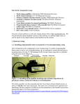
1
Model 1421
Distribution Amplifier
Installation and Operating Instructions
The 1421 Distribution Amplifier provides four independent, wide bandwidth outputs from one video input.
The unit is color compatible and also includes a video presence circuit to visually indicate proper system
operation.
Part number 8000- 0852- 01 B0
The software/firmware furnished with this equipment is confidential to and is copyrighted by AMERICAN
DYNAMICS. It is not to be copied or disclosed in any manner without the express written consent of
AMERICAN DYNAMICS. The software/firmware is furnished to the purchaser under a license for use on
a single system.
Note: Information furnished by AMERICAN DYNAMICS is believed to be accurate and reliable.
However, no responsibility is assumed by AMERICAN DYNAMICS for its use; nor for any infringements
of other rights of third parties, which may result from its use. No license is granted by implications or
otherwise under any patent or patent rights of AMERICAN DYNAMICS.
The installation of this product should by made by qualified
service personnel and should conform to all local codes.
The lightning flash with an arrowhead symbol,
within an equilateral triangle, is intended to alert the
user to the presence of uninsulated “dangerous
voltage” within the product’s enclosure that may be
sufficient magnitude to constitute a risk of electric
shock to persons.
CAUTION
RISK OF ELECTRIC SHOCK
!
DO NOT OPEN
CAUTION: To reduce the risk of electric shock, do
not remove covers (or back).
No user-serviceable parts inside.
!
The exclamation point within an equilateral triangle
is intended to alert the user to the presence of
important operating and maintenance (servicing)
instructions in the literature accompanying the
product.
Refer servicing to qualified service personnel.
WARNING
To reduce the risk of fire or shock hazard, do
not expose this product to rain or moisture.
UNPACKING AND INSPECTION
Unpack carefully. This is an electronic product and should
be handled as such. Compare the items received with the
packing list with your order.
Be sure to save:
1. The shipping cartons and insert pieces. They are the
safest material in which to make future shipments of
the product.
2. The IMPORTANT SAFEGUARDS sheet.
3. These Installation and Operating Instructions.
Warning: This product ge nerates, uses, and can
MAINTENANCE
radiate radio frequency energy and if not installed
User maintenance of this unit is limited to external
and used in accordance with the instruction manual, cleaning and inspection. For specific recommendations,
may cause interference to radio communications. It refer to the IMPORTANT SAFEGUARDS sheet packaged
has been tested and found to comply with the limits with this product.
for a Class A computing device pursuant to Part 15
INSTALLATION AND SERVICE
of FCC Rules, which are designed to provide
If you require information during installation of this
reasonable protection against such interference
product or if service seems necessary, contact the
when operated in a commercial environment.
American Dynamics Video Products Division. You must
Operation of this product in a residential area is
obtain a Return Authorization Number and shipping
likely to cause interference in which case the user
instructions before returning any product for service.
at his own expense will be required to take
Do not attempt to service this product yourself. Opening
whatever measures may be required to correct the
or removing covers may expose you to dangerous voltages
interference.
or other hazards. Refer all servicing to qualified personnel.
QA301D
Table of Contents
PRODUCT DESCRIPTION .............................................................................................1
FEATURES ........................................................................................................................1
INSTALLATION ...............................................................................................................1
CONNECTIONS................................................................................................................2
OPERATION .....................................................................................................................2
DESCRIPTION, FEATURES, and INSTALLATION
____________________________________________________________________________________________________________
Figure 1 - 1421 Front Panel
PRODUCT DESCRIPTION
INSTALLATION
The 1421 Distribution Amplifier provides four independent, wide
bandwidth outputs from one video input. The unit is color
compatible and also includes a video presence circuit to visually
indicate proper system operation.
Mounting
1421 Distribution Amplifiers are supplied as desk-top units. For
rack mounting, 2117 Series rack-mount kits are available . 1421s
are quarter-rack units. Up to four quarter-rack units such as a
1404-switcher, a 1470A Screen Splitter, or a 1461 Single Channel
Motion Detector may be mounted in a single 19” by 1 ¾” rack.
One or two quarter-rack units may be mounted with half-rack
units, such as the 1440B Date/Time Generator.
FEATURES
v FOUR VIDEO OUTPUTS
Each output is driven by an independent isolated amplifier. Shorts,
opens, or noise on one output have no effect on the other outputs.
No manual adjustment is required.
IF YOU ENCOUNTER ANY PROBLEMS
OPERATING THIS UNIT, OR NEED
TECHNICAL ASSISTANCE:
v VIDEO LOSS DETECTION
The Power LED on the front panel indicates the presence or
absence of an input video signal. An associated pull-down output
can trigger a user-supplied alarm device.
1
CONNECTIONS and OPERATION
____________________________________________________________________________________________________________
1
2
O
U
T
P
U
T
S
1
2
3
4
IN
120V60HZ
Figure 2 - 1421 Rear Panel
CONNECTIONS
Power Connection
Video Inputs
1421 models operate from 120 VAC, 50/60 Hz. 1421/X models
operate from 240 VAC, 50/60 Hz. The operating voltage is shown
on the back panel. A 3-wire power cord and plug are attached.
The BNC video input connector located on the back panel is
terminated internally in 75 ohms. Therefore, if a video cable is
looped through a monitor between the camera and the amplifier,
that monitor’s termination switch should be set to HI-Z.
Otherwise, the camera output “sees” a double termination, which
reduces its video signal level.
OPERATION
There are no adjustments or controls on the 1421 Distribution
Amplifier. The video signal connected to its input is reproduced
on each of the four independent outputs.
The front panel LED power and video presence indicator provides
the following information:
LED OFF: No input AC power
LED GREEN: Norman operation – AC power is on and a video
input is present
LED RED: Video loss – AC power is on, but no video input is
present
The LED video presence or loss indicator is not affected by shorts
or opens on any of the four outputs. It indicates the presence of an
input signal and the proper operation of the internal circuits of the
1421.
VIDEO OUTPUTS
The four BNC video outputs are designed to be terminated in a 75ohm load. Therefore, if any of the video output cable are looped
through monitors or other accessories, be sure their terminations
are set to HI-Z. Only the last unit on the line should have its
termination set to 75 ohms. All four outputs may be used
simultaneously. Shorts or opens on any one output do not affect
the other outputs. Unused outputs should be left disconnected and
are not terminated.
VIDEO LOSS DETECTION OUTPUT
An open collector pull-down output is available on the rear panel
to signal a loss of video to other equipment. When no video is
present (LED red), the output transistor is on (pulled down). This
output can sink up to 20 ma from external circuits or devices
operating form a maximum of 24 V DC. Multiple 1421s may be
connected in parallel so that a loss of video on any one unit signals
an alert.
External Video Loss 5-Pin Connector
Pin 1 - Common
Pin 2 - Video Loss Output
Caution: Do not apply external voltages to this connector.
Precautions should be taken, especially with multiple amplifiers,
to prevent incorrect connections which may damage the amplifier.
2
SPECIFICATIONS
Supply Voltage:
Power:
1421 – 120VAC, 50/60 Hz
1421X – 230 VAC, 50/60 Hz
3 watts
Mounting: Free standing or quarter-rack mount
Size:
1.88” H x 7.2”D x 4.3”W (48 x 183 x 109 mm)
Weight:
1 lb (0.5 Kg)
Designed and built by
AMERICAN DYNAMICS
Part number 8000- 0852- 01 B0