1
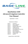
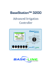
Field Guide to
Soil Moisture Sensor
Use in Florida
The Field Guide to Soil Moisture Sensor Use in Florida was produced for the St. Johns River Water Management District
(SJRWMD) by the Program for Resource Efficient Communities (PREC) at the University of Florida (UF).
Primary Author................................Brent T. Philpot, MS, Research Associate, PREC
Supervising Specialist......................Dr. Michael D. Dukes, Associate Professor and Irrigation Specialist
Department of Agricultural and Biological Engineering (ABE), UF
Supporting Specialist for Outreach and Continuing Education
Dr. Kathleen C. Ruppert, Associate Extension Scientist, PREC
Contributors.....................................Stacia Davis, MS Student, ABE, UF
Melissa Haley, MS, PhD Student, ABE, UF
Bernard Cardenas-Lailhacar, MS, ABE, UF
Mary Shedd, MS Student, ABE, UF
Reviewers:.........................................Hays P. Henderson, ASLA, Houston Cuozzo Group, Inc., Stuart, Fla.
Dr. Barbra C. Larson, Statewide Coordinator
Florida Yards and Neighborhoods, UF
Russ Prophit, CID, CIC, CLIA, President
Precise Irrigation Design and Consulting, Inc., Winter Haven, Fla.
Andrew K. Smith, CIC, CID, CLIA
Irrigation Association External Affairs Director, Boyne City, Mich.
Brian Alderfer, Land Development Manager
Mercedes Corporate Land Division, Melbourne, Fla.
Layout and Design...........................Barbara Haldeman, Technical Editor and Layout Specialist, PREC
DISCLAIMER
The University of Florida does not in any way endorse specific brands of soil moisture sensor control systems. This
document only endorses specific best practices for proper installation, calibration, and maintenance of soil moisture
sensor control systems. It should be noted that soil moisture sensor (SMS) controllers are most effective when installed
in conjunction with efficient irrigation design, installation, and maintenance. SMS controllers will not fix fundamental
problems with an irrigation system and proper practices in areas such as component selection, head spacing, equipment
location, and hydraulic principles should be addressed first. Additionally, current research has shown that SMS
controllers are most effective when the irrigation controller is programmed to water seven days a week. With increasing
demand on water resources Florida’s water management districts have widely implemented water restrictions, which are
in some cases one day per week. At some point it will be necessary to consider whether effective technologies such as
SMS controllers should be allowed to operate free from restrictions provided they have been properly installed and are in
effective working order.
Published May 2008
© 2008 St. Johns River Water Management District
Table of Contents
I. Introduction..........................................................................................................................................................................1
A. The Role of the Modern Soil Moisture Sensor in Florida......................................................................................1
B. University of Florida Research....................................................................................................................................2
II. Installation.............................................................................................................................................................................5
Step 1: Establish the Sensor Location............................................................................................................................5
Step 2: Install the Sensor................................................................................................................................................12
Step 3: Install the Controller..........................................................................................................................................22
Step 4: Connect the Wiring...........................................................................................................................................22
III. Calibration...........................................................................................................................................................................25
Step 1: Establish the Controller Set Point...................................................................................................................25
Step 2: Calibration..........................................................................................................................................................26
IV. Maintenance........................................................................................................................................................................29
A. Evaluate Soil Moisture Sensor Functioning............................................................................................................29
B. Other Information......................................................................................................................................................31
V. Troubleshooting..................................................................................................................................................................33
Important Reminders.....................................................................................................................................................33
VI. References and Resources..................................................................................................................................................35
A. Irrigation Scheduling.................................................................................................................................................35
B. General Irrigation ......................................................................................................................................................35
C. UF Soil Moisture Sensor Research..........................................................................................................................35
D. Water Efficiency.........................................................................................................................................................35
VII. Appendixes..........................................................................................................................................................................37
Appendix A: Where to Install a Soil Moisture Sensor (SMS)..................................................................................37
Appendix B: Irrigation Scheduling per Irrigation Event for Florida Turf Grasses (minimum).............................38
Appendix C: Monthly Net Irrigation Requirements for Florida...............................................................................39
i
Introduction
I. Introduction
A. The Role of the Modern Soil Moisture Sensor in Florida
Water is an extremely valuable yet seriously stressed resource in Florida. Nevertheless, in-ground, time-controlled
irrigation systems that use potable water are standard in the landscapes of a majority of newly built homes. Ideally,
homeowners adjust their irrigation controllers in response to seasonal weather patterns. However, homeowners often
make no adjustments, leaving the irrigation timer set at fixed watering levels regardless of plant water requirements. As a
result, irrigation systems frequently apply significantly more water than landscapes require.
Conventional irrigation controllers used in residential landscapes allow irrigation at scheduled times for specified periods
of time. For example, a controller can be scheduled to initiate a 15-minute irrigation event every Monday and Friday at 6
a.m. These controllers do not account for weather conditions and will irrigate at the scheduled time even if it is raining.
To minimize this unnecessary irrigation, Florida Statute 373.62 requires that all newly installed residential irrigation
systems have an add-on rain shutoff device (rain sensor) installed and maintained that bypasses time-scheduled irrigation
events during, and for a period after, rain events. While rain sensors improve the water-use efficiency of time-controlled
irrigation systems, controllers still use fixed watering schedules, which are historical estimates of landscape water needs.
These schedules can neglect seasonal and annual climatic variations and do not reflect actual landscape conditions.
Soil moisture sensor (SMS) controllers measure soil moisture content where it is most vital to plants: in the active root
zone. SMS systems connect to irrigation controllers and check soil moisture content prior to scheduled irrigation events.
If the SMS controller determines that soil moisture content is above a user-defined set point, the irrigation cycle is
bypassed. This allows SMS controllers to function similarly to rain sensors and bypass irrigation during rainy periods,
but also to minimize irrigation when plants do not require
additional water. Under ideal conditions, a properly
working SMS controller does not stress plants or decrease
turf grass quality because it allows the irrigation system to
apply the amount of water actually needed to meet plant
water requirements.
Figure 1 shows the circuit created by an SMS control
system. If moisture is above the set point, the circuit in the
SMS controller is left open and no irrigation occurs. If the
soil moisture is below the set point, the circuit is closed
and the scheduled irrigation occurs.
Different SMS technologies are used to measure soil
moisture content in landscapes. One is an improved
granular matrix sensor (GMS) technology, which has
been used in agricultural irrigation systems for decades.
Some modern soil moisture sensors use electrical
conductivity to measure soil moisture content. Two types
of SMS use this technology: a time domain transmissivity
(TDT) sensor and a time domain reflectometry (TDR)
sensor. All sensor types are discussed in general terms in
Figure 1. General diagram of an irrigation system with a soil moisture
this field guide.
sensor (SMS) control system
1
Introduction
Useful Terms
Evapotranspiration (ET) – A combination of water transpiration from vegetation and evaporation from the soil and
plant surfaces; also known as consumptive use.
Field capacity – The moisture remaining in the soil following wetting and gravitational drainage until water has ceased
drainage.
Irrigation zone – An area in a landscape that is irrigated by a single zone (solenoid) valve; also known as a hydrozone.
Net irrigation requirement – The amount of water needed to replace water lost through evapotranspiration minus the
amount of rainfall that contributes water to the plant root zone (i.e., effective rainfall).
Permanent wilt point – Moisture content of the soil after a plant can no longer extract moisture at a sufficient rate for
wilted leaves to recover overnight or when placed in a saturated environment.
Plant water requirement – The amount of water needed to replace water lost through evapotranspiration.
Representative area – An area possessing the average qualities of the irrigation zone(s) controlled by the SMS control
system.
Soil moisture sensor (SMS) – The soil moisture sensor probe that is installed in the ground within the root zone.
SMS controller – Collective term sometimes used for the entire SMS system.
Transpiration – Movement of water from the soil, into the roots, up the plant stems, and finally out of the plant leaves
into the air as vapor.
B. University of Florida Research
Beginning in 2004, a research group in the Agricultural and Biological Engineering Department at the University of
Florida (UF) initiated a series of ongoing studies on soil moisture sensors (SMS) in turf grass. These studies have been
conducted using one SMS probe per irrigation system in both highly controlled research facilities and in homeowner
landscapes. To date, all studies have shown that SMS controllers produce substantial water savings in comparison to
conventional controllers and rain sensors while maintaining acceptable turf quality.
Study 1
In the first study, in a controlled research environment in Gainesville, Fla. (2004–2005), four SMS controllers
were tested:
• Acclima RS500
• RainBird MS-100
• WaterWatcher DPS-100
• Irrometer 200SS-5
2
Introduction
Rainfall during this study period was average to above average, resulting in high sensor-based water savings. Treatments
were compared to a two-day-a-week, time-based irrigation schedule, based on Dukes and Haman (2002a), using no
sensor technology. All four SMS controller treatments applied less irrigation water than the time-based schedule with
no sensor (Table 1). Three of the SMS controllers significantly outperformed a rain shutoff device set at ¼ inch (6 mm):
the SMS-controlled irrigation application reduction ranged from 70% to 92%, while rain sensors averaged a 34% savings
(Cardenas-Lailhacar, in press).
Two other sensors, the BaseLine WaterTec S100 and the Lawn Logic LL-1004, have been added to ongoing research at
the UF Gainesville facility.
Table 1: Water Savings in Wet Conditions in a Research Setting
Treatment
Percentage of Water Saved
2 days/week without sensor
0%
2 days/week with rain sensor
34%
2 days/week SMS average
72%
* SMS = Soil moisture sensor
Study 2
In the second study, at a controlled research environment in Citra, Fla. (2006), two SMS controllers were tested: the
Acclima RS500 and the LawnLogic LL-1004. Rainfall during this study was below average, resulting in lower SMScontrolled water savings compared to Study 1 savings. These water savings ranged from 10% to 28% (Table 2). Rain
sensors saved 11% to 23% compared to the conservative irrigation schedule (Shedd et al., 2007)
Table 2: Water Savings in Dry Conditions in a Research Setting
Treatment
Percentage of Water Saved
2 days/week without sensor
0%
2 days/week with rain sensor
10–23%
2 days/week SMS average
10–28%
* SMS = Soil moisture sensor
Study 3
The third study tested one sensor controller, the Acclima RS500, on residential landscapes in the city of Palm Harbor,
Fla. Preliminary results show that sensors are successful for irrigation water-use savings at single-family homes. From
June 2006 through March 2007, homes with soil moisture sensors demonstrated water savings of 51% compared to
homes with an irrigation controller only (Haley and Dukes, 2007).
3
Introduction
Disclaimer
Procedures for proper installation, calibration, and maintenance vary by SMS brand. Generally, each manufacturer’s
installation manual provides adequate instructions for effective installation. Installation manuals should be referenced
for specific instructions, especially for wiring, calibration, and troubleshooting. Valuable lessons have been learned during
testing conducted by the University of Florida (UF) that can provide additional guidance. This field guide describes these
lessons and other information required for general best practices. However, installers and maintenance professionals
should always refer to the most current manufacturer’s installation manual for model-specific instructions. An SMS
cannot make up for a poorly working irrigation system, and sensors should be installed on systems that are in good repair
and which have been designed for optimum efficiency.
4
Installation
II. Installation
The four main installation steps are:
1. Establish the sensor location.
2. Install the sensor.
3. Install the controller.
4. Connect the wiring.
Step 1: Establish the Sensor Location
An SMS is most effective when placed in a location representative of the zone(s) that the sensor is controlling. If multiple
sensors are being used in a landscape (i.e., one sensor per zone), each sensor should be placed in an area representative of
the specific zone it is controlling. If one sensor is being used for the entire landscape (the sensor is controlling multiple
zones), the average water requirement of the entire landscape should be considered as the baseline. To gain the most
benefit in a multiple SMS probe system, a sensor should be located in each irrigation zone, known as a hydrozone.
When used to control an entire irrigation system with only one sensor, SMS controllers should be installed in an
irrigation zone for turf grass. Instructions in this field guide focus on landscapes composed primarily of turf grass.
Typically, turf grass will need more frequent irrigation than most other plant types in a landscape. Therefore, if turf
grass watering requirements are met, other plants in the landscape will receive sufficient irrigation, presuming that all
hydrozones are properly designed and scheduled for the associated plant materials. Care must be taken before using SMS
control systems on stress-prone plants, such as annuals. If SMS controllers are being used for landscape plants, trees, or
other types of ground cover, installers should refer to the manufacturer’s installation manual for location instructions and
specifications.
Variations in soil type and condition, adjacent land use, shading, and drainage patterns all can cause a sensor to read an
unrepresentative soil moisture content, which can result in too much or too little irrigation. If one area does not represent
the average condition of the SMS-controlled area, SMS placement in that location should be avoided.
Location in the landscape – Soil moisture sensors should be placed at the driest location relative to the average of the
SMS-controlled zone(s). These driest locations may include
• Areas with significant sun exposure
• Lot-specific high elevation points
Depth in the ground – Sensor probes should be placed within the root zone, in contact with relatively undisturbed soil
that is representative of the irrigated landscape area. Contact with disturbed soil with a higher (or lower) amount of void
space will likely result in unrepresentative soil moisture content readings. However, if the soil in the entire landscape is
disturbed (i.e., fill material is used to elevate and level a new construction site), a disturbed area would be representative.
5
Installation
A. Optimal Installation Areas
The following are optimal areas for sensor installation:
• In the turf grass root zone (Figure 2), if turf grass is used
as the representative plant type
Purpose: Provide sufficient irrigation to the area with the
greatest water requirement. Generally, turf grass will have
the highest water requirement relative to other landscape
plants. If the turf grass requirements are met, other plant
water requirements should also be met, presuming that all
irrigation zones are properly designed and scheduled for the
associated plant materials.
• In a relatively sunny area, if full sun is representative of the
landscape
Figure 2. Bermuda grass root zone
Purpose: Provide sufficient irrigation to the area with
the greatest water requirement. Often, landscapes have turf grass lawns in full sun. These areas have higher
evapotranspiration (ET) rates and, therefore, higher water requirements. In new landscapes, these areas may have a
poor soil type that does not hold water well.
• In the driest representative area possible, considering all other factors
Purpose: Provide sufficient irrigation to the area with the greatest water requirements. While other areas might
receive more water than required, the sensor should not be installed in an area where it will bypass irrigation events
necessary to meet the landscape’s water requirements as a whole.
• In the center of the irrigation zone, or in an area receiving an average, or slightly less than average, amount of
irrigation relative to other irrigated areas in the landscape
Purpose: Ensure that the SMS is not located in an area with a greater than average soil moisture content. In some
cases, irrigation distribution may be nonuniform and sensor placement in an area with higher relative irrigation could
result in too many bypassed irrigation events, thus preventing plants from receiving their needed irrigation water
requirements.
Note: It should be noted that some SMS controllers require the sensor to be located in the area irrigated by the last
valve to run, so the sensor is not wetted before all valves have been allowed to irrigate. Sometimes this means the
stations on the controller should be re-sequenced so the area where the sensor has been installed is last.
6
Installation
B. Areas to Avoid – General
When establishing the SMS location, certain areas and site conditions should be avoided.
INSTALL the sensor at least 5 feet away from:
To avoid:
• A property line��������������������������������������������������������������irrigation overspray from a neighbor’s yard
• An impervious surface��������������������������������������������������runoff from impervious surfaces and compacted soil around
impervious surfaces
• A structure (e.g., house, porch, shed, etc.).�����������������compacted soil, shade, and runoff
• A depression/swale������������������������������������������������������naturally high soil moisture content areas
• On-site treatment and disposal systems
(e.g., septic tanks, drain fields)������������������������������������high moisture areas
INSTALL the sensor at least 3 feet away from:
To avoid:
• A plant bed��������������������������������������������������������������������higher runoff, shade, and unrepresentative plant roots
C. Areas to Avoid – High Moisture
Some areas in the landscape can have a higher moisture content due to increased water inflow or reduced water
outflow. For example, directed stormwater runoff can cause an
area to have a higher moisture content, while shade can cause
the same effect by reducing evapotranspiration. These areas
with a higher moisture content relative to the surrounding
landscape should be avoided.
INSTALL the sensor at least 5 feet away from:
To avoid:
• A downspout�����������������������������������������������������������������areas with higher amounts of inflowing storm water relative to
the rest of the landscape
• An overhang������������������������������������������������������������������areas with higher or lower amounts of inflowing storm water
relative to the rest of the landscape
• A hose bib����������������������������������������������������������������������areas with higher amounts of inflowing water relative to the
rest of the landscape
• An air-conditioner system condensate line����������������areas with higher amounts of inflowing water relative to the
rest of the landscape
• The drip line of a tree canopy��������������������������������������areas with a lower ET rate and higher moisture content
(unless SMS is specifically used for trees)
• A shaded north side of the home (if possible)�����������areas with a lower ET rate and higher moisture content
7
Installation
D. Areas to Avoid – Disturbed Sites and Soils
In some areas it is difficult to tell if the soil has been, or will be, compacted. Installers should use their best knowledge of
the landscape history and projected use to determine the SMS location. If it is known that the soil has been, or will be,
compacted in one particular area, the SMS should be installed elsewhere.
INSTALL the sensor at least 4 feet away from:
To avoid:
• A construction road������������������������������������������������������compacted soils and runoff from compacted soils
INSTALL the sensor at least 3 feet away from:
To avoid:
• An area with plant debris (e.g., tree stump)���������������compacted soils and materials intermixed with soils that are
unrepresentative of the landscape as a whole
• An area with fill dirt (if fill dirt is unrepresentative
of the entire landscape)������������������������������������������������soils that are unrepresentative of the landscape as a whole
• Buried material (e.g., cable, water, or sewer line)�������soils and materials that will result in a soil moisture reading
that is unrepresentative of the landscape as a whole or that
may be disturbed in the future due to maintenance or repair
Note: •Check with local building codes before beginning to dig or install an irrigation system.
•See Appendix A for a condensed table containing priorities for determining SMS placement.
E. Landscape Examples
To better understand how these rules should be applied, three different landscape installation examples are shown on the
following pages. The three depicted conditions are:
1. A typical landscape
2. A Florida Water StarSM landscape
3. A preserved vegetation landscape
In all three examples:
1. Green-dotted areas are optimal locations for SMS placement.
2. Blue-striped areas are secondary locations that might be appropriate in some cases.
3. Red wavy areas are not suitable SMS locations.
Drawings are not to scale, to emphasize landscape features.
Note: Specific site features and conditions could preclude installation in areas that appear to be optimal or secondary
installation locations. Always perform a site inspection to determine if any site specific conditions make an area
less suitable for sensor probe installation.
8
Installation
In a Typical Landscape
Figure 3 depicts a typical residential landscape characterized by large turf grass areas (greater than 60% of the entire
landscape) and very few trees. There are many optimal sensor locations in this landscape, and it should be relatively
easy to determine the best location within a short period of time. A newly developed landscape of this type will have fill
material that must be considered during SMS installation.
Figure 3. Example of a typical residential landscape
Legend
Green-dotted areas:
Optimal locations for SMS placement.
Blue-striped areas:
Secondary locations that might be
appropriate in some cases. Areas are
more shaded than green in this case.
Red wavy areas:
Not suitable SMS locations.
9
Installation
In a Florida Water StarSM Landscape
Figure 4 depicts a hypothetical Florida Water StarSM (water-efficient) landscape, composed of 60% or less turf grass
and 40% or greater planting beds, natural areas, or drought-tolerant ground covers. Reduced turf grass area decreases
the number of optimal SMS locations. There are optimal areas in the front yard, but fewer such areas exist throughout
the Florida Water StarSM landscape when compared to a typical landscape. Selection of a sensor location in this type of
landscape might require more attention than in a typical setting.
Figure 4. Example of a Florida Water StarSM (water-efficient) landscape
Legend
10
Green-dotted areas:
Optimal locations for SMS placement.
Blue-striped areas:
Secondary locations that might be
appropriate in some cases. Areas are
more shaded than green in this case.
Red wavy areas:
Not suitable SMS locations.
Installation
In a Preserved Vegetation Landscape
Figure 5 depicts a residential landscape with a high percentage of preserved vegetation. This landscape has more shaded
areas, less turf grass, and potentially higher soil moisture content. Because of the landscape layout, the optimal areas for
SMS installation might be considered secondary areas in other landscapes. However, the goal is to place the SMS in a
representative area. If the landscape only has secondary areas, the SMS should be installed in an area that will ensure all
areas receive adequate irrigation.
Figure 5. Example of a landscape with preserved vegetation
Legend
Green-dotted areas:
Optimal locations for SMS placement.
Blue-striped areas:
Secondary locations that might be
appropriate in some cases. Areas are
more shaded than green in this case.
Red wavy areas:
Not suitable SMS locations.
11
Installation
F. Include SMS Location in New Landscape Plans
Specifying the SMS location in the landscape and irrigation design plan prior to installation can help to simplify the
installation process and reduce human error in the field. If the location is predefined, the installer will spend less time
surveying the landscape to determine an optimal sensor location. Nevertheless, the predefined location should be checked
according to instructions provided in step 1, Establish the Sensor Location, to ensure that unforeseeable factors do not
make the area a poor choice for an SMS location.
G. Mark and Measure the Sensor Location
Documentation of the sensor location can make future maintenance easier by providing a record of the SMS location
for future homeowners, irrigation contractors, and maintenance professionals. Foremost, the SMS installer should
specifically mark the sensor location on a copy of the as-built irrigation plan and display the plan adjacent to the
irrigation timer. Next, installers should measure and record the distance and approximate angle from the SMS to two
permanent points in the landscape (triangulation) and note this also on the as-built plan. Finally, installers should
consider adding tracer wire for future SMS probe location.
Step 2: Install the Sensor
A sensor’s installation orientation depends upon its type, size, and shape. Installers should always refer to the
manufacturer’s installation manual for specific installation instructions. Until more information regarding sensor
installation becomes available, the sensor should be installed in the turf grass root zone. In new landscapes, the SMS
will often be installed prior to installation of the turf grass sod. In this case, the sensor probe should be buried in the soil
at the midpoint of the maximum plant root density (typically < 6 inches) and the turf grass sod laid on top. For sensor
installation in existing turf grass, an area of sod must be removed to accommodate the sensor probe and a trench must
be dug to run the SMS wiring. The following installation instructions suggest that a wiring trench be dug after SMS
installation. It is perfectly reasonable to dig the hole for the SMS probe and the trench at the same time and then install
the sensor and wiring.
Note: • Always use a square-point ditching shovel for SMS installation (Figure 6).
• Always check for proper system operation before burying the sensor probe
and wiring.
• Bury the sensor probe within the midpoint of the maximum plant root
density
• In new landscapes where there is no existing root zone, the installer should
consider the root depth of any potential plantings in the landscape design,
then estimate the midpoint necessary for correct sensor probe depth.
Figure 6. Square-point ditching
shovel required for SMS
installation
12
Installation
A. Sensor Types
Three types of residential sensor probes are now typically available in
Florida: (1) flat, (2) node, and (3) rod. Installation procedures vary by
type and are described individually in the sections below.
1. Flat Sensor Probes
Two types of long, flat sensor probes are commonly found. Sensors
with this type of probe often use time domain transmissivity (TDT) to
measure soil moisture content. Orientation should occur as follows:
Exposed wave guides – If the sensor probe is long, flat, and has
exposed rounded wave guides (steel rods), it should be installed
horizontally and with the wide side facing up (Figure 7).
Figure 7. Probe with exposed wave guides
Encased wave guides – If the sensor probe is long, flat, and has a solid
surface encasing the wave guides, it should be installed horizontally and
with the thin side facing up (Figure 8).
Flat Probes in New Landscapes
In landscapes with new turf grass sod being installed, the sensor
should be buried approximately 3 inches below the soil surface,
with the turf grass sod placed on top of the soil as follows:
1. Dig an 8-inch by 8-inch hole to a depth of 3 inches.
2. Insert the sensor into the bottom of the hole according
to the sensor orientation specifications (Figure 9).
Figure 8. Probe with encased wave guides
(Photo courtesy of Base Line)
3. Dig the trench for the wiring connection (See section
B); connect the wiring according to the manufacturer’s
instructions; and check for proper SMS controller
functioning.
4. Fill in the hole and trench, completely covering the sensor
and wiring.
5. Mark the sensor location with a flag to prevent damage
during the sod installation.
6. Install the turf grass sod, pressing firmly over the sensor.
Figure 9. Installation of flat probe SMS in new
landscape (bare soil)
13
Installation
Flat Probes in Existing Landscapes
Two methods can be used to install flat sensors in existing landscapes.
Option 1: Bury the SMS probe in a shallow hole by rolling back a square of cut turf grass.
1. Using a square-point ditching shovel, cut a square piece of turf grass sod to the midpoint of the maximum
plant root density and just large enough to cover the entire probe (Figure 10).
2. Remove the cut square of turf grass sod by rolling it back to expose the soil below (Figure 11).
Figure 10. Cutting a square of turf grass
large enough to cover entire probe
Figure 11. Turf grass square rolled back
3. Place the sensor on top of the soil and gently press it into the soil (Figure 12).
4. Dig the trench to run wiring (see section B), make the connections according to the manufacturer’s
specifications, and check for proper SMS controller functioning.
5. Roll back the cut square of turf grass sod to completely cover the sensor probe (Figure 13).
Figure 12. SMS installed in root zone by rolling
back the sod
14
Figure 13. Turf grass rolled back over sensor
Installation
6. Gently compact the turf grass sod, making sure that there are no channels that will allow water to seep in and
pool around the SMS probe (Figure 14). Additional soil can be added on top of the sensor location so that it
may wash into any remaining gaps.
Figure 14. Gently compacting the turf grass area
Option 2: Slide the SMS into the sidewall of a hole by cutting the turf grass roots.
1. Dig an 8-inch by 8-inch hole to a depth of 6 to 8 inches, ideally creating a sod plug that can be pulled out
whole (Figure 15).
2. Horizontally, cut the turf grass roots in an area large enough to fit the sensor into the wall of the hole within
the midpoint of the maximum root density by using a “metal slicing tool” and mallet (Figure 16).
Figure 15. Removal of turf grass and soil plug
Figure 16. Root cutting procedure preparing soil for
SMS installation
15
Installation
3. Using the manufacturer’s specified orientation, slide the sensor probe into cut area at the midpoint of the
maximum turf grass root density (Figure 17).
4. Gently compact the soil above the sensor to ensure that there is sufficient contact between the sensor probes
and the soil (Figure 18).
Figure 17. SMS probe installed within root zone
Figure 18. Compaction of soil around sensor to reduce void
space and ensure adequate connection between
SMS probe and soil
5. Dig the trench to run the wiring (see section B); make the connections according to the manufacturer’s
specifications; and check for proper SMS controller functioning.
6. Replace the cut square of turf grass and soil to completely cover the sensor probe (Figure 19).
Figure 19. Soil and turf grass plug replaced, covering SMS
probe prior to burying wire
7. Gently compact the cut square of turf grass sod, making sure that there are no channels that will allow water
to seep in and pool around the SMS probe. Additional soil may be added on top of the sensor location to fill
in any remaining gaps.
16
Installation
2. Node Probes
An SMS with node probes should be installed vertically or at a 45-degree angle within the root zone. Sensors with
this type of probe typically use granular matrix technology to measure soil moisture. Because this type of sensor
might have additional specifications, always refer to the manufacturer’s installation manual. Figure 20 shows a
granular matrix sensor (GMS) being installed in a new landscape.
Figure 20. SMS node probes in a new landscape installation
Figure 21. SMS node probes installed in turf root zone
Node Probes in New Landscapes
In landscapes with new turf grass sod, the sensor probes should be inserted just below where the sod roots join the
native soil.
1. Soak the sensor in water prior to installation.
2. Cut a small V-trench in the soil.
3. Insert the sensor into the side of the trench at a 45-degree angle (see Figure 21).
4. Dig the trench to run the wiring (see section B); make the connections according to the manufacturer’s
specifications; and check for proper SMS controller functioning.
5. Replace the plug of soil cut out, completely covering the sensor and keeping the wires at the bottom of the
trench. Be sure it is compacted similarly to the surrounding soil.
6. Mark the sensor location with a flag to prevent damage during the sod installation.
7. Install the turf grass sod.
Node Probes in Existing Landscapes
In landscapes with established turf grass, the sensor probes should be inserted into the side of a shallow cut out
section of turf and then the turf plug replaced.
1. Soak the sensor in water prior to installation.
2. Cut a small V-trench to expose the turf roots.
17
Installation
3. Insert the sensor into the side of the trench at a 45-degree angle (see Figure 21).
4. Dig the trench to run the wiring (see section B); make the connections according to the manufacturer’s
specifications; and check for proper SMS controller functioning.
5. Replace the plug of turf cut out, completely covering the sensor and keeping the wires at the bottom of the
trench.
6. Tamp the replaced turf plug down firmly.
3. Rod Probes
If a sensor has rod probes, it should be installed with all probes positioned toward the ground at an approximate
45-degree angle. This allows the probes to read soil moisture content in the most active portion of the root zone. Sensors
with these types of probes typically use time domain reflectometry (TDR) to measure soil moisture content.
Rod Probes in New Landscapes
In landscapes with new turf grass sod, the sensor probes should be inserted into a shallow hole and the turf grass laid
on top.
1. Dig a 4-inch by 4-inch hole to a depth of 2 inches.
2. Insert the sensor into the bottom of the hole at a 45-degree angle.
3. Dig the trench to run the wiring (see section B); make the connections according to the manufacturer’s
specifications; and check for proper SMS controller functioning.
4. Fill in the hole, completely covering the sensor.
5. Mark the sensor location with a flag to prevent damage during the sod installation.
6. Install the turf grass sod.
Rod Probes in Existing Landscapes
In a landscape with existing turf grass, the SMS should be inserted in the turf grass root zone in the sidewall of
a hole.
Dig an 8-inch by 8-inch hole to a depth of 6 inches, ideally
creating a sod plug that can be pulled out whole.
1. Insert the sensor probes to penetrate the root zone
in the soil of the hole’s sidewall at a 45-degree angle
(Figure 22), using a depth in the midpoint of the
maximum turf grass root density of approximately 2 to
3 inches. (If the rods are inserted at a 2-inch depth they
would reach to a depth of approximately 4 inches.)
2. Gently compact the turf grass and soil above the SMS
to ensure that the probes are in sufficient contact with
the soil.
18
Figure 22. SMS rod probes partially inserted into the
turf grass root zone of undisturbed soil
Installation
3. Dig the trench to run wiring (see section B); make the connections according to the manufacturer’s
specifications; and check for proper SMS controller functioning.
4. Replace the cut square of turf grass sod.
5. Gently compact the turf grass and soil plug, making sure that there are no channels that will allow water to
seep in and pool around the SMS probe. Additional soil can be added on top of the sensor location to fill in
any remaining gaps.
B. Run Sensor Cable to Zone Valve
SMS wire connection requires digging a trench that may vary in length depending upon the installation distance. Wiring
provided in the installation kit is typically long enough to span the distance between the SMS probe and the irrigation
valve or SMS controller. If necessary, additional wiring should be added to allow for SMS probe installation in an
optimal location. Depending on the circumstances, either mechanical or manual means can be used to dig the trench.
For simplicity, instructions here discuss wiring the SMS probe to an irrigation valve.
Note: Inadvertent cutting of the wiring is one of the greatest threats to SMS operation. It is highly recommended that all
in-ground wiring be encased in conduit to protect it from being severed.
Mechanical Digging in New Landscapes
If the SMS is being installed in a newly developed landscape, it commonly will be installed prior to turf grass installation.
In this case, a mechanical device, such as an earth saw trencher, chain trencher, or vibratory plow, can be used to dig the
wiring trench. A mechanical trencher creates a deeper trench (8 to 12 inches) that will further protect the wiring from
being cut by aerators, edgers, shovels, and other landscape maintenance devices. While the trench might be deeper in this
case, the soil moisture sensor probe should still be installed in the root zone at the midpoint of the maximum density
(typically < 6 inches).
1. After establishing the sensor location, mark the location with a flag.
2. Determine where the connection between the SMS probe and the valve will be made and mark it with a flag.
3. Dig the trench between the two flags to a depth of 8 to 12 inches.
4. Install the SMS probe at the end of the newly dug trench in the midpoint of the maximum density of the root
zone.
5. Insert the wiring into the bottom of the trench until it reaches the point where the connection to the irrigation
valve will be made.
6. Make the proper wiring connections according to the manufacturer’s specifications and check for proper SMS
controller functioning.
7. Fill in the trench completely.
Note: If the irrigation system is being installed at the same time as the SMS system, the irrigation trench can be used
for running the SMS wiring. Additionally, wiring should be placed underneath the irrigation pipes for further
protection. Not all sensors are wired the same and connections should be made according to the manufacturer’s
specifications.
19
Installation
Manual Digging In Existing Landscapes
Two manual digging methods, lift trench and slit trench, can be
used for running wiring in existing landscapes.
a. Lift Trench Method
A lift trench is made by inserting a square ditching shovel at
a 45-degree angle to the ground surface and while the soil
is lifted, inserting the wiring underneath. This method is
appropriate when no conduit is being used and there is little
risk of cutting the wire. It is relatively simple and reduces the
chances of killing turf grass above the trench.
Figure 23. Beginning lift trench
1. Insert square ditching shovel into the soil at a
45-degree angle to a depth of 6 inches (Figure 23).
2. Lift the shovel to a 90-degree angle or to where there
is enough room to insert the SMS wiring at a depth
of 6 inches in the bottom of the trench (Figure 24).
3. While the shovel is still in the trench, insert the
wiring into the trench to a depth of 6 inches, only
running the wire halfway across the shovel head
(Figure 25).
Figure 24. Lifting shovel within the lift trench to create
room for SMS wiring
4. Repeat steps 1 to 3 until the wiring reaches the
irrigation valve.
5. Make the wiring connections according to
manufacturer’s specifications and check for proper
SMS controller functioning.
6. Gently compact the lifted trench on the top and the
edge of the turf grass and soil to close the trench.
Continue to compact the entire length of the trench
until it is completely closed (Figure 26).
Figure 25. Closing the lift trench
Figure 26. Placing sensor wires while continuing to lift the
trench
20
Installation
b. Slit Trench Method
A slit trench is a wedge made in the ground. This method can be slightly more time-consuming than the lift trench
method, while also leaving a line of dead turf after installation. However, this method should be used when running
wiring through conduit for additional protection (Figure 27). When manually digging a trench, the slit trench
method including conduit is recommended.
1. Insert a square ditching shovel into the ground at a 90-degree angle.
2. While standing on both sides of the shovel head, rock the shovel, spreading the soil to a depth of
approximately 6 inches.
3. Continue steps 1 and 2 until the trench reaches from the SMS probe to the irrigation valve.
4. Insert the wiring through a section of conduit long enough (in total) to protect the entire length of the
wiring.
5. Insert the wiring and conduit into the bottom of the trench, making sure that the wiring reaches from the
SMS probe to the irrigation valve or SMS controller.
6. Make the wiring connections according to manufacturer’s specifications and check for proper SMS
functioning. Gently compact the trench by stepping on both sides of the opening in order to completely close
the entire trench.
Figure 27. A conventional slit trench should only be used
when placing wiring in conduit
21
Installation
Step 3: Install the Controller
There are two recommended locations for an SMS controller:
• Adjacent to the irrigation timer on an interior wall (e.g., garage)
• Adjacent to the irrigation timer in a weatherproof housing on the exterior of the home
Note: Do not install the SMS controller outside without a weatherproof housing and ultraviolet (UV) protection
from the sun.
After determining the SMS controller location, install it on the wall adjacent to the timer. Make sure it is not blocked
when the timer door is open. Installers should always refer to the manufacturer’s specifications when installing the
SMS controller.
Step 4: Connect the Wiring
Figure 28 shows a general wiring configuration of the SMS probe, the irrigation valve, the SMS controller, and the
irrigation timer. This illustration does not depict the wiring configuration for all sensors, and installers should always
refer to the manufacturer’s illustration manual for specific instructions to make wiring connections.
Figure 28. Example of a general wiring configuration for an SMS-controlled
irrigation system
22
Installation
A. Connect Sensor to the Zone Valve
Generally, sensors can be wired either to an irrigation valve or directly to the SMS controller. It is recommended that the
SMS be wired to the nearest zone valve, if possible, to facilitate sensor installation in the most representative area. Some
sensors must be wired to the last zone valve for the entire system to be controlled by the SMS controller.
Wiring configurations vary among brands. Installers should always refer to specific wiring diagrams in the manufacturer’s
installation manual. Figures 29 through 34 show a connection being made between a sensor and a zone valve.
Note: Direct burial yellow or red (DBY or DBR) connectors should be used on all connections between the sensor and
the zone valve to prevent moisture intrusion and to provide a secure connection.
Figure 30. Uncover the irrigation zone valve box
Figure 29. Direct burial yellow
(DBY) connector
Figure 32. Prepare the soil moisture sensor
and zone valve for connection
Figure 31. Disconnect the existing wiring
connection between the irrigation
timer and zone valve
Figure 33. Connect the wires from the soil
moisture sensor to the zone valve
Figure 34. Enclose all wire nuts in direct
burial connectors
23
Installation
B. Connect SMS Controller to the Irrigation Timer
The connections from the SMS controller to the irrigation timer also vary by brand and should always be done according
to specifications in the manufacturer’s installation manual. Figures 35 through 38 show a controller being wired to an
irrigation controller.
24
Figure 35. Open irrigation timer, exposing wires to be connected to
SMS controller
Figure 36. Install SMS controller adjacent to the irrigation timer
on the side opposite the timer door hinges
Figure 37. Connect SMS controller wiring to the irrigation timer
wiring
Figure 38. Power the SMS controller and the irrigation timer and
check for proper functioning
Calibration
III. Calibration
Step 1: Establish the Controller Set Point
Prior to calibration and set point establishment, it is necessary to determine how much water can be held in the root
zone where the SMS is located. To achieve this, the installer should saturate the area immediately around the SMS
location. Within 24 hours of saturation, the controller will read the soil moisture content, which should be close to field
capacity (i.e., no further water drainage below the root zone). Generally, the recommended soil moisture set point is 75%
of the field capacity. Two primary methods for establishing field capacity, bucket and irrigation, are recommended. A
third method, calibration after a significant rainfall, can be used in situations where rainfall occurs shortly after sensor
installation.
Option 1. Bucket method
1. Pour a 5 gallon bucket of water directly over the
installed and connected SMS (Figure 39).
2. Wait 24 hours.
3. Perform the calibration according to the manufacturer’s
specifications.
Option 2. Irrigation method
1. Specify a watering cycle period, according to Appendix
B, that will apply 1 inch of water to the zone where the
sensor is installed.
2. Using the manual start button, start the irrigation
system for the zone where the SMS is located (Figure
40).
Figure 39. Establishing the controller set point—bucket
method (arrow points to sensor location)
3. Wait 24 hours from the end of the irrigation cycle.
4. Perform the calibration according to the manufacturer’s
specifications.
Option 3. Post rainfall method
1. Wait 24 hours from the end of a significant rainfall
event (1 inch or more).
2. Perform the calibration according to the manufacturer’s
specifications.
Note: The soil surrounding the sensor should not receive any water
during the 24-hour post-saturation period. If rainfall occurs
during this period, then the soil will not be at field capacity at
the end of 24 hours and the procedure must be repeated once
the soil dries.
Figure 40. Manual start of the irrigation timer to
saturate area around SMS for calibration
25
Calibration
Step 2: Calibration
Always refer to the manufacturer’s specifications for detailed SMS controller calibration procedures. Calibration
instructions are brand-specific and cannot be adequately addressed for all systems here in this field guide.
Timing With Plant Establishment
In new landscapes, plants (including turf grass) are often installed at about the same time as irrigation systems. During
root establishment, new plants have their highest water needs. Water management districts and local governments specify
rules that typically allow for 30 to 60 days for the establishment of new plantings. However, these rules vary by location
and should be appropriately referenced for accuracy in all cases.
Two SMS calibration issues arise during a plant establishment period. First, the irrigation system will be set to meet the
water requirements of newly installed plants and the SMS controller will be turned off during this period. Second, plant
root depth and soil qualities in the root zone will change significantly during establishment. As a result, the controller
should be calibrated post-establishment when the irrigation timer is reset for normal operation.
Recommended Set Points
Always refer to the manufacturer’s installation manual for specific set point recommendations. Generally, an SMS
controller should be set at an initial soil moisture set point equivalent to 75% of field capacity. Table 3 shows volumetric
moisture content (VMC) settings for several field capacity VMCs. The VMC setting varies by SMS controller brand
(see the manufacturer’s installation manual).
Table 3: Recommended SMS Controller Set Points
26
Field Capacity
10%
15%
20%
25%
Moisture Setting (threshold)
8%
11%
15%
19%
Calibration
Irrigation Controller Scheduling
The irrigation controller, not the SMS controller, initiates scheduled irrigation events. It is extremely important that the
irrigation controller be set for an irrigation schedule appropriate for the irrigation system, location, plant need, season,
and your water management district’s requirements. Appendix B contains recommended irrigation scheduling for Florida
turf grasses. To establish the run-time for a particular zone, use the following procedure:
1. Determine your region (e.g., central Florida).
2. Determine the season (e.g., autumn).
3. For each zone, determine the appropriate application rate (e.g., 0.5 inches/hour for typical rotors, 1.5 inches/hour
for typical spray heads; see Dukes and Haman, 2002a).
4. Determine the appropriate run-time for each zone according to Appendix B (e.g., 85 minutes for a zone with an
application rate of 0.50 inches/hour during autumn months).
5. Program the specific run-time into the irrigation timer for each zone.
6. Repeat for each zone until all zones have been programmed appropriately.
Note: For additional assistance in setting the irrigation controller, see the Florida Automated Weather Network
(FAWN) Urban Irrigation Scheduler at http://fawn.ifas.ufl.edu/tools/urban_irrigation/.
27
Calibration
28
Maintenance
IV. Maintenance
SMS control system manufacturers do not specify routine maintenance procedures. A properly working SMS controller
should not result in excessive irrigation application. If the system is applying excessive amounts of irrigation, it needs to
be inspected by an irrigation contractor. The principle maintenance task described here is monitoring of the irrigation
system’s functioning.
Note: As previously mentioned, to improve monitoring and maintenance of an SMS, the sensor location should be
marked on an as-built design plan and the plan displayed next to the irrigation timer.
A. Evaluate Soil Moisture Sensor Functioning
Step 1: Review Water Bill/Meter
The water bill should be reviewed to estimate how much water is being used for irrigation. For new homes, initial
irrigation is likely to be higher for plant establishment and water consumption should be compared with water use
for a similarly existing landscape. After extended occupancy, it will be possible to compare current water use with past
water use. In existing homes, it is fairly straightforward to compare irrigation between pre-and post-SMS installation
conditions.
For a complete evaluation tool, the following should be known:
1. Amount of water used for irrigation as reported in the monthly utility bill
2. Irrigated landscape area taken either from an irrigation plan or estimated based on the lot and house size
a. Estimate Monthly Outdoor Water Use
Single Meter
If one meter combines monitoring of domestic indoor water use and outdoor irrigation water use, the two uses
should be separated. Two methods can be used for this calculation.
Method 1. Assume the average Floridian uses 53 gallons per day indoors (Marella, 2004, p. 15). Multiply this by the
number of people in the household to calculate indoor domestic water use.
Formula:
53 gallons /day × ____ people in household × ____ days in month
= _____ monthly indoor water use
Method 2. Calculate the monthly domestic indoor use based on the water bill during a period of low, net irrigation
requirement (winter months). If the irrigation timer is set properly, irrigation during those winter months should be
near zero and total consumption can act as a baseline for monthly domestic indoor water consumption throughout
the year. To determine monthly outdoor water use, subtract the monthly indoor use from the monthly total water
use.
Formula:
____ total monthly water use –____ monthly indoor use = ____ monthly outdoor use
29
Maintenance
Dual Meter
If an independent water meter is installed to record irrigation consumption, calculating SMS performance is
relatively straightforward. The only required calculation is estimation of the irrigated landscape area (square feet).
b. Compare to Appendix C
Appendix C contains monthly recommended net irrigation volume in gallons by region. Net irrigation is calculated
by subtracting average historical rainfall from historical evapotranspiration (ET). To compare your monthly irrigation
application to the net irrigation requirements in Appendix C, take the following steps:
1. Determine your region (e.g., central Florida).
2. Determine the season (e.g., autumn).
3. Estimate your irrigated landscape area in square feet (e.g., 2,000 square feet).
4. Find the recommended net irrigation volume in gallons (e.g., 4,300 gallons) from Appendix C. (Use the steps
found on page 29 to help you calculate the volume.)
5. Compare this recommendation to the amount of monthly outdoor water use from your utility bill (e.g., 4,000
gallons). When comparing, be sure that the amount of water from your bill is for one month, as some utilities have
a bimonthly billing cycle.
6. If you are applying excessive amounts of irrigation volume compared to the recommended net irrigation volume,
the SMS controller system should be inspected by an irrigation contractor. (In this example, the irrigation volume
is reasonable. Check again the following month.)
Step 2: Manual Start
Another method for monitoring the SMS controller function
is a manual start of the irrigation controller. This is done by
pressing the irrigation controller’s manual start button (the
SMS controller is activated). When the manual start is pressed,
the irrigation system should not come on. If a watering cycle is
activated under these conditions, there is a problem with the
system’s functioning and an irrigation contractor should be
contacted (Figure 41).
Step 3: Observation
Figure 41. Manual start of irrigation timer while SMS
controller is “on hold” to test proper operation
In some instances, observation of plant health can indicate whether the SMS control system is functioning properly.
Visual evidence can tell you if the landscape is getting either too much or too little water. Certain conditions, as shown
in Table 4, are caused by too much or too little irrigation. Too much irrigation can mean that the SMS is not working
properly or that the set point is too wet. Too little irrigation typically indicates that the set point is too dry. Also, it is
important to remember that over- or under irrigation can result from improper scheduling.
30
Maintenance
B. Other Information
Periodic Recalibration
SMS controller set points can be increased or decreased periodically to achieve a homeowner’s desired irrigation results.
Reasons for this periodic recalibration could be seasonal weather variation, water table variation, improper sensor
location, or site alteration. If the system is installed properly and the landscape has not been altered, recalibration is
only recommended once a year as part of a routine annual irrigation system maintenance program. Annual recalibration
should be done beginning with step 1 in the Calibration section of this field guide.
Table 4. Methods for Testing Soil Moisture Sensor Functioning
Method
Possible Causes of Failure
Malfunction
Threshold
Schedule
1. Review of water bill/meter
X
X
X
2. Manual system activation
X
X
3. Check for wet/dry areas
X
X
X
Fungus
X
X
X
Dollar weed
X
X
X
X
X
X
X
→Wet
→Dry
Chinch bugs
Other Considerations
Fertilization companies often activate a watering cycle after fertilizer application. An SMS controller might be turned
off at this time to prevent it from bypassing the irrigation system. The SMS controller must be turned back on.
Instructions for these and other professionals (e.g., pest control) should be included in the design plan displayed next
to the irrigation timer.
Sensor and Controller Replacement
Contact your distributor for replacement components. If they are unable to meet your needs, contact the manufacturer
directly.
31
Maintenance
32
Troubleshooting
V. Troubleshooting
SMS control systems have troubleshooting procedures that are typically model-specific, and operators should always
refer to the manufacturer’s installation manual for troubleshooting guidance.
Important Reminders
• Be certain the sensor is connected to the valve that controls irrigation in the sensor’s location.
• Make sure the correct wire is connected to the sensor zone terminal on the irrigation timer.
• Make sure all in-ground wiring connections are enclosed within a direct burial connector.
• Make sure the circuit that connects the sensor, zone valve, SMS controller, and controller is properly connected
(i.e., no short circuit)
33
Troubleshooting
34
Resources
VI. References and Resources
A. Irrigation Scheduling
Augustin, B.J. (2000). Water requirements of Florida turfgrasses. BUL200, Institute of Food and Agricultural Sciences,
University of Florida, Gainesville, Fla. Available: http://edis.ifas.ufl.edu/pdffiles/EP/EP02400.pdf.
Dukes, M.D., and, D.Z. Haman (2002a). Operation of residential irrigation controllers. CIR1421, Institute of Food and
Agricultural Sciences, University of Florida, Gainesville, Fla. Available: http://edis.ifas.ufl.edu/AE220.
Florida Automated Weather Network (FAWN) Urban Irrigation Scheduler. http://fawn.ifas.ufl.edu/tools/
urban_irrigation/.
St. Johns River Water Management District. (2006). Summary of lawn and landscape irrigation rule and exceptions.
Available: http://www.sjrwmd.com/programs/outreach/conservation/irrigation_rule/index.html.
B. General Irrigation
Dukes, M.D., and D.Z. Haman, (2002b). Residential irrigation system rainfall shutoff devices. ABE325, Institute of
Food and Agricultural Sciences, University of Florida, Gainesville, Fla. Available: http://edis.ifas.ufl.edu/AE221.
Haley, M.B., M.D. Dukes, and G.L. Miller. (2007). Residential irrigation water use in Central Florida. Journal of
Irrigation and Drainage Engineering 133(2), 427–434.
C. UF Soil Moisture Sensor Research
Cardenas-Lailhacar, B., M.D. Dukes, and G.L. Miller. (In press). Sensor-based automation of irrigation on
bermudagrass, during wet weather conditions. Journal of Irrigation and Drainage Engineering.
Dukes, M.D., B. Cardenas-Lailhacar, and G.L. Miller. (2005). Residential Irrigation Based on Soil Moisture. Resource
June/July, 4–6.
Dukes, M.D., B. Cardenas-Lailhacar, S. Davis, M.B. Haley, and M. Shedd. (2007). Smart water application technology
(SWAT) evaluation in Florida. Proceedings of the American Society of Agricultural and Biological Engineers (ASABE)
Annual International Meeting, 2007. Minneapolis, Minn.
Haley, M., and M.D. Dukes. (2007). Evaluation of sensor-based residential irrigation water application. ASABE 2007
Annual International Meeting, Minneapolis, Minn., 2007. ASABE Paper No. 072251.
Shedd, M., M.D. Dukes, and G.L. Miller. (2007). Evaluation of evapotranspiration and soil moisture-based irrigation
control on turfgrass. Proceedings of the ASCE EWRI 2007 World Environmental and Water Resources Congress
2007. Tampa, Fla.
D. Water Efficiency
Florida Water Star. http://sjr.state.fl.us/programs/outreach/conservation/water_star/water_star.html.
Marella, R.L. (2004). Water withdrawals, use, discharge, and trends in Florida, 2000. U.S. Geological Survey Scientific
Investigations Report 2004-5151.
35
Resources
36
Appendixes
VII. Appendixes
Appendix A: Where to Install a Soil Moisture Sensor (SMS)
Prerequisites for Placement
•
•
•
•
Within the root zone of turf grass
In sunniest area possible
Within the driest area possible considering all other factors
Within the center of an irrigation zone
Main Areas to Avoid
Away from structures (house, garage, shed, etc.)
Minimum Distance Away
5 feet
• Away from a property line
5 feet
• Away from depressions/swales
5 feet
• Away from impervious surfaces
5 feet
• Away from septic tanks/drainfields
5 feet
• Away from plant beds
3 feet
High Moisture Areas to Avoid
• Away from an overhang
5 feet
• Away from an air-conditioner system condensate line
5 feet
• Away from a hose bib
5 feet
• Away from north (shaded) side of the home
5 feet
• Away from tree canopy
5 feet
• Away from a downspout
5 feet
Disturbed Areas to Avoid
• Away from construction roads
4 feet
• Away from areas with plant debris (i.e., tree stump)
3 feet
• Away from areas with fill dirt
3 feet
• Away from buried materials
2 feet
37
Appendixes
Appendix B: Irrigation Scheduling per Irrigation Event for Florida Turf
Grasses (minimum)
Season
North
Central
South
Season
0.50 inches/hour
North
Central
South
1.50 inches/hour
Winter
5
25
50
Winter
0
10
15
Spring
75
110
80
Spring
25
35
25
Summer
80
95
100
Summer
25
30
35
Autumn
55
85
65
Autumn
20
30
20
0.75 inches/hour
1.75 inches/hour
Winter
0
15
35
Winter
0
5
15
Spring
50
70
55
Spring
20
30
25
Summer
55
65
65
Summer
25
25
30
Autumn
40
55
45
Autumn
15
25
20
1.00 inches/hour
2.00 inches/hour
Winter
0
15
25
Winter
0
5
15
Spring
40
55
40
Spring
20
25
20
Summer
40
45
50
Summer
20
25
25
Autumn
30
45
35
Autumn
15
20
15
1.25 inches/hour
Season = Month with highest net requirement
Winter
0
10
20
Spring
30
44
30
Summer
35
40
40
Autumn
25
35
25
•
•
•
•
Events occur twice per week
60% system efficiency
Calculated from historical evapotranspiration (ET) and effective rainfall
Numbers rounded for convenience
Adapted from: Augustin, 2000; and Dukes and Haman, 2002a
Note: Appendix B is based on historical rainfall and might not represent necessary run times under atypical conditions
(e.g., drought, wet conditions). Current conditions should be taken into account when setting the timer.
38
Appendixes
Appendix C: Monthly Net Irrigation Requirements for Florida
Table 1: Monthly Net Irrigation Requirements for North Florida
Net Irrigation Requirement (Historical ET – Rainfall)
Volume (gallons) of Irrigation per Irrigated Area (square feet)
Maximum
Application
(inches) 1
2,000
4,000
6,000
8,000
10,000
Spring
3.70
4,600
9,200
13,800
18,500
23,000
Summer
3.21
4,000
8,000
12,000
16,000
20,000
Autumn
3.51
4,400
8,800
13,100
17,500
21,900
Winter
1.44
1,800
3,600
5,400
7,200
9,000
Annual Total
11.86
14,800
29,600
43,300
59,200
73,900
Season
Irrigated Area (square feet)
Under normal rainfall conditions
1
•
•
•
•
•
•
Requirements are for Gainesville, Fla.
Seasons are the months with the highest irrigation requirement.
Spring = May
Summer = June
Autumn = September
Winter = December
Adapted from Augustin, 2000
Table 2: Monthly Net Irrigation Requirements for Central Florida
Net Irrigation Requirement (Historical ET – Rainfall)
Volume (gallons) of Irrigation per Irrigated Area (square feet)
Maximum
Application
(inches) 1
2,000
4,000
6,000
8,000
10,000
Spring
4.73
5,900
11,800
17,700
23,600
29,500
Summer
4.68
5,800
11,700
17,500
23,300
29,200
Autumn
3.41
4,300
8,500
12,800
17,000
21,300
Winter
1.19
1,500
3,000
4,500
6,000
7,400
Annual Total
14.01
17,500
35,000
52,500
69,900
87,400
Season
Irrigated Area (square feet)
Under normal rainfall conditions
1
•
•
•
•
•
•
Requirements are for Orlando, Fla.
Seasons are the months with the highest net irrigation requirement.
Spring = May
Summer = August
Autumn = September
Winter = November
Adapted from Augustin, 2000
39
Appendixes
Table 3: Monthly Net Irrigation Requirements for South Florida
Net Irrigation Requirement (Historical ET – Rainfall)
Volume (gallons) of Irrigation per Irrigated Area (square feet)
Maximum
Application
(inches) 1
2,000
4,000
6,000
8,000
10,000
Spring
4.12
5,100
10,300
15,400
20,500
25,700
Summer
4.06
5,100
10,100
15,200
20,200
25,300
Autumn
2.96
3,700
7,400
11,100
14,800
18,500
Winter
2.07
2,600
5,200
7,700
10,300
12,900
Annual Total
13.21
16,500
33,000
49,400
65,800
82,400
Season
Irrigated Area (square feet)
Under normal rainfall conditions
1
•
•
•
•
•
•
Requirements are for Ft. Myers, Fla.
Seasons are the months with the highest irrigation requirement.
Spring = May
Summer = August
Autumn = November
Winter = December
Adapted from Augustin, 2000
40