1
INSTALLATION CONNECTIONS
3
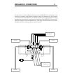
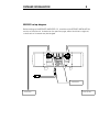
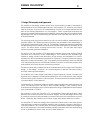
The first section of the installation instructions for the AMPLIFIER v12 is a diagram of the
default four channel configuration required to bring this amplifier into an operating
mode. These brief steps will allow you to begin operating your system. Make sure during
installation that the main AC power switch on the back of the AMPLIFIER v12 is turned off.
While the diagram may be self explanatory, we strongly recommend that you read the
detailed instructions following this introductory section.
PREAMPLIFIER
SPEAKER 3
SPEAKER 2
CH 1 OUTPUT
CH 2 OUTPUT
CH 1 INPUTS
CH 2 INPUTS
CH 3 INPUTS
UNBALANCED
BALANCED
BALANCED
UNBRIDGED
UNBRIDGED
BRIDGED-CHANNEL 1
AND CHANNEL 2
BRIDGED-DO NOT USE GROUNDS
BRIDGED-CHANNEL 3
AND CHANNEL 4
BRIDGED-DO NOT USE GROUNDS
FOR CONTINUED PROTECTION
CAUTION
MODEL
WA R N I N G
SERIAL NUMBER
1. REPLACE FUSE WITH SAME
TYPE AND RATING
T
E
C
H
N
O
L
O
G
I
E
S
I
N
C
.
VOLTAGE REQUIREMENT
HZ
POWER REQUIREMENT
VA
MANUFACTURED IN THE USA
TO RAIN OR MOISTURE
!
AC LINE FUSE CHART
VOLTAGE
100V
~
AC LINE INPUT
FUSE AND VOLTAGE SELECTOR
120V
8 AMP
SLOW BLOW 5 x 20mm
4 AMP
SLOW BLOW 5 x 20mm
240V
4 AMP
SLOW BLOW 5 x 20mm
!
DO NOT ALLOW AMPLIFIER OUTPUTS
TO COMMON BETWEEN CHANNELS,
SLOW BLOW 5 x 20mm
220V
!
TO PREVENT ELECTRIC SHOCK, DO NOT
REMOVE COVER. NO USER SERVICEABLE
PARTS INSIDE. REFER SERVICING TO
QUALIFIED SERVICE PERSONNEL.
NOTE
MAIN POWER
FUSE TYPE
8 AMP
CH 4 OUTPUT
BRIDGED
INPUT
AGAINST SHOCK OR FIRE:
2. DO NOT EXPOSE THIS UNIT
CH 3 OUTPUT
CH 4 INPUTS
UNBALANCED
BRIDGED
INPUT
OR CONTACT CHASSIS OR INPUT
120
GROUNDS, OR TO BE CONNECTED
TO ANY ACTIVE CURRENT SOURCE.
SEE SERIAL TAG FOR POWER
REQUIREMENTS, REMOVE POWER
CORD BEFORE CHANGING
FUSE OR LINE VOLTAGE
FUSE VALUE -SEE FUSE CHART
VOLTAGE SELECTIONSEE OPERATION MANUAL
OFF
ON
THIS PRODUCT
IS DESIGNED,
ENGINEERED
AND BUILT IN THE UNITED
STATES OF AMERICA.
PREAMPLIFIER
SPEAKER 1
SPEAKER 4