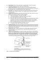
1
PowerVu® Model D9850
Program Receiver
Installation and Operation Guide
Please read this entire guide
Veuillez lire entièrement ce guide
Bitte das gesamte Handbuch durchlesen
Sírvase leer completamente la presente guía
Si prega di leggere completamente questa guida
Important
Please read this entire guide before you install or operate this product. Give particular
attention to all safety statements.
Important
Veuillez lire entièrement ce guide avant d'installer ou d'utiliser ce produit. Prêtez une
attention particulière à toutes les règles de sécurité.
Zu beachten
Bitte lesen Sie vor Aufstellen oder Inbetriebnahme des Gerätes dieses Handbuch in seiner
Gesamtheit durch. Achten Sie dabei besonders auf die Sicherheitshinweise.
Importante
Sírvase leer la presente guía antes de instalar o emplear este producto. Preste especial
atención a todos los avisos de seguridad.
Importante
Prima di installare o usare questo prodotto si prega di leggere completamente questa
guida, facendo particolare attenzione a tutte le dichiarazioni di sicurezza.
NOTICES
Trademark Acknowledgments
Scientific-Atlanta, PowerVu, and the Scientific-Atlanta logo are registered trademarks of
Scientific-Atlanta, Inc.
Dolby Digital is a trademark of Dolby Laboratories Licensing Corp.
The DVB logo is a trademark of the DVB Digital Video Broadcasting Project.
Imitext is a trademark of Screen Subtitling Systems Limited.
All other trademarks shown are trademarks of their respective owners.
Publication Disclaimer
Scientific-Atlanta, Inc., assumes no responsibility for errors or omissions that may appear
in this publication. Scientific-Atlanta reserves the right to change this publication at any
time without notice. This document is not to be construed as conferring by implication,
estoppel, or otherwise any license or right under any copyright or patent, whether or not
the use of any information in this document employs an invention claimed in any existing
or later issued patent.
Copyright
© 2004 Scientific-Atlanta, Inc. All rights reserved. Printed in USA.
Information in this publication is subject to change without notice. No part of this
publication may be reproduced or transmitted in any form, by photocopy, microfilm,
xerography, or any other means, or incorporated into any information retrieval system,
electronic or mechanical, for any purpose, without the express permission of ScientificAtlanta, Inc.
QUICK SETUP – READ ME FIRST!
Scientific-Atlanta
PowerVu Model D9850 Program Receiver
If you want to receive programs using a PowerVu scrambled service, fill in the
information below and follow the Step-by-Step instructions.
Before you start, fill in the following:
Program to receive:
Program Provider:
Satellite & Transponder:
Polarization:
Downlink Frequency &
Symbol rate:
(Note: For typical C-band, Downlink freq.= 5.150 GHz – L-band (GHz))
Network ID:
Receiver User Address (UA):
(found on the rear panel)
Step-by-Step Instructions
1.
Connect the L-Band signal to the RF IN connector.
Note that LNB power is only available via the RF input #1 for multiple RF
models. The factory default setting for RF 1 LNB power is OFF. (If you need
the receiver to power your LNB, details are provided in step 11.)
2.
Connect video and audio outputs to a TV monitor.
3.
Connect the AC power source. Wait for the receiver to fully boot up. Once
ready, the default status menu will appear [CH:XXX Name:XXXX] For an
initial installation, the channel number will be 0 and the channel name will
be "Not Available".
4.
Press MENU to move from the initial display into the Main Menu system.
5.
For Free-to-Air (i.e., in-the-clear) service (from other non-S-A uplinks) setup,
refer to steps 6 and 7 to change the default PSI decoder settings to avoid
processing specific system tables which may not be used by other uplinks. If
you want to receive a PowerVu signal only, skip to step 8.
4006105 Rev B PowerVu D9850 Program Receiver Installation and Operation Guide
iii
For Free-to-air Service Setup only
6.
On the Main Menu, press the right arrow key ( ) so the cursor (♦) is to the
left of the Setup menu item. Press the Select button to display the Setup
Menu.
Then press the right arrow key ( ) again so the cursor (♦) is to the left of
the More menu item. Press the Select button to display the More Features
Menu.
Press the right arrow key ( ) again so the cursor (♦) is to the left of the PSI
menu item. Press the Select button to display the PSI menu.
7.
Edit/change the default PSI settings to the Free-to Air settings displayed in
the table below by using the down arrow key to move through the available
items until the desired option is displayed.
Menu
Parameter
PowerVu
(Defaults)
Single RF Input
PowerVu
w/Disaster
Recovery
Free-to-air
Settings
PSI
Stream Tuning Mode
Basic
Basic
Auto
PSI
CA
STD
STD
Open
PSI
Input Select
Preset
RF Map
Preset
Not required
Required
Not required
Preset (RF)
Orbital Positioning
8.
Return to the Main Menu. Then press the right arrow key ( ) so the cursor
(♦) is to the left of the Preset/Input menu item. Press the Select button to
display the Preset/Input menu.
9.
Edit the Active Preset (default decoder settings) by entering values for the
Downlink Frequency, Symbol Rate, Network ID, Polarization and Input.
(Use the down arrow key to move through the available menus until the
desired option is displayed.)
10.
For C-Band, enter the parameters below; otherwise refer to the section on
the Presets Menu for details on RF settings.
•
•
•
•
•
11.
iv
5.15 for L01
0.0 for L02
0.0 for Xover
select RF#
select the Satellite you want to use to receive the signal.
If you are not using the receiver to power the LNB, confirm that Power is set
to Off and L0 Select is set to LO1.
Press the down arrow to go to the next menu.
PowerVu D9850 Program Receiver Installation and Operation Guide 4006105 Rev B
Note that if you require LNB Power for the RF signal input, set Power to
either 13, 18 or Polariser. Refer to the Presets Menu section to choose the
appropriate setting.
12.
At this time, you should get a (signal) Lock. (Check RF, if not).
13.
Press MENU, the message Acquiring Network Information should display.
14.
If successful, the message Network Acquired, Save Changes? displays. Select
Continue to accept the changes. You should now get video on the monitor.
15.
If you see the message Not Authorized, please contact your program provider
and provide them with your User Address for authorization. To find your
Decoder Address, from the Main Menu, move the cursor to the About menu
item and press Select.
For additional setup assistance, please contact your program provider or Scientific-Atlanta technical support.
4006105 Rev B PowerVu D9850 Program Receiver Installation and Operation Guide
v
vi
PowerVu D9850 Program Receiver Installation and Operation Guide 4006105 Rev B
Safety Precautions
Protect yourself from electric shock and your system from damage!
• This product complies with international safety and design standards. Observe all safety
procedures that appear throughout this guide, and the safety symbols that are affixed to
this product.
• If circumstances impair the safe operation of this product, stop operation and secure this
product against further operation.
Avoid personal injury and product damage! Do not proceed beyond any symbol until you fully
understand the indicated conditions!
You will find this symbol in the literature that accompanies this product.
It indicates important operating or maintenance instructions.
You may find this symbol in the literature that accompanies this product.
It indicates a live terminal; the symbol pointing to the terminal device.
You may find this symbol in the literature that accompanies this product.
It indicates a protective earth terminal.
You may find this symbol in the literature that accompanies this product.
It indicates excessive or dangerous heat.
Power
Important! This product is Protection Class II.
This product plugs into a socket-outlet. The socket-outlet must be near this product, and must be
easily accessible. Connect this product only to the power source that is indicated on the back
panel of this product. This product does not have a mains power switch, the power cord serves this
purpose.
Enclosure
Do not allow moisture to enter this product. Do not open the enclosure of this product unless
otherwise specified. Do not push objects through openings in the enclosure of this product.
Cables
Always pull on the plug or the connector to disconnect a cable. Never pull on the cable itself. Do
not walk on or place stress on cables or plugs.
Factory service
Refer service only to service personnel who are authorized by the factory.
Règles de sécurité
Protégez-vous des risques d'électrocution et protégez votre système contre les endommagements
éventuels.
• Ce produit respecte les standards internationaux de sécurité et de conception. Veuillez
observer toutes les procédures de sécurité qui apparaissent dans ce guide, ainsi que les
symboles de sécurité qui figurent sur le produit.
• Si, du fait des circonstances, ce produit cesse de fonctionner normalement, cessez de
l'utiliser et empêchez-en l'utilisation future.
Évitez le risque de blessures et de dommages aux produits! Ne procédez à aucune tâche tant que
vous n'aurez pas entièrement assimilé les conditions indiquées par un symbole!
Ce symbole figure dans la documentation accompagnant ce produit. Il indique
d'importantes instructions de fonctionnement ou d'entretien.
Ce symbole peut être attaché à ce produit. Il indique une borne sous tension; la direction
indique la borne.
Ce symbole peut être attaché à ce produit. Il indique une borne de terre de protection.
Ce symbole peut être attaché à ce produit. Il indique une température excessive ou
dangereuse.
4006105 Rev B PowerVu D9850 Program Receiver Installation and Operation Guide
vii
Alimentation
Important! Ce produit fait partie de la classe II.
Ce produit se branche dans une prise murale. Cette dernière doit être placée à proximité du
produit et doit être facilement accessible.
Ne branchez ce produit qu'à la source d'alimentation indiquée sur son panneau arrière.
Si ce produit n'a pas d'interrupteur d'alimentation générale, le cordon d'alimentation remplit ce
rôle.
Enceinte
Ne laissez pas l'humidité pénétrer dans ce produit.
N'ouvrez pas l'enceinte de ce produit, sauf instructions contraires.
Ne forcez pas d'objets dans les ouvertures du boîtier.
Câbles
Tirez toujours sur la prise ou le connecteur pour débrancher un câble, Ne tirez jamais directement
sur le câble.
Ne marchez pas sur les câbles ou les prises et n'y exercez aucune pression.
Réparations effectuées à l'usine
Ne confiez les travaux de réparations qu'au personnel autorisé par l'usine.
Sicherheitsvorkehrungen
Schützen Sie sich gegen elektrischen Schlag, und Ihr Gerät gegen Beschädigung!
• Dieses Gerät entspricht internationalen Sicherheits-und Ausführungsnormen. Beachten
Sie alle in diesem Handbuch enthaltenen Sicherheitshinweise sowie die am Gerät
angebrachten Warnzeichen.
• Sollten örtliche Umstände den sicheren Betrieb dieses Gerätes beeinträchtigen,
schalten Sie es ab und sichern es gegen weitere Benutzung.
Vermeiden Sie Verletzungen sowie Beschädigung des Gerätes! Wenn Sie zu einem der
folgenden Warnzeichen gelangen, nicht weiterarbeiten, bis Sie seine Bedeutung voll verstanden
haben!
Dieses Symbol erscheint auf dem Gerät und/oder in der ihm beiliegenden Literatur. Es bedeutet
wichtige, zu beachtende Betriebs-oder Wartungsanweisungen.
Wenn dieses Zeichen am Gerät angebracht ist, warnt es vor einer spannungsführenden Stelle.
Dieses Symbol kennzeichnet auf dem Gerät die Anschlußstelle der Sicherheitserde.
Wenn dieses Zeichen am Gerät angebracht ist, warnt es vor heißen Stellen, die zu Verbrennungen
führen können.
Netzspannung
Wichtig! Dieses Gerät ist Schutzklasse II.
Das Gerät ist an einer Steckdose anzuschließen. Diese muß sich leicht zugänglich in
unmittelbarer Nähe des Gerätes befinden.
Die Netzversorgung muß den auf der Rückwand des Gerätes angegebenen Werten entsprechen.
Falls sich kein Hauptschalter am Gerät befindet, dient das Netzkabel diesem Zweck.
Gehäuse
Das Innere des Gerätes ist vor Feuchtigkeit zu schützen.
Das Gehäuse ist nicht zu öffnen.
Niemals einen Gegenstand durch die Gehäuseöffnungen einführen!
Kabel
Hierzu grundsätzlich am Stecker oder Verbindungsstück und niemals am Kabel selber ziehen.
Nicht auf die Kabel oder Stecker treten oder diese einer Zugbelastung aussetzen.
Hersteller-Wartung
Wartungsarbeiten sind nur durch vom Hersteller autorisierte Techniker vorzunehmen.
viii
PowerVu D9850 Program Receiver Installation and Operation Guide 4006105 Rev B
Precauciones de seguridad
¡Protéjase contra la electrocución y proteja su sistema contra los daños!
• Este producto cumple con los criterios internacionales de seguridad y diseño. Observe
todas los procedimientos de seguridad que aparecen en esta guía, y los símbolos de
seguridad adheridos a este producto.
• Si las circunstancias impiden la operación segura de este producto, suspenda la
operación y asegure este producto para que no siga funcionando.
¡Evite lastimarse y evite dañar el producto! No avance más allá de cualquier símbolo hasta
comprender completamente las condiciones indicadas!
Encontrará este símbolo en el impreso que acompaña a este producto. Este símbolo indica
instrucciones importantes de funcionamiento o mantenimiento.
Es posible que este símbolo esté pegado al producto. Este símbolo indica un terminal vivo, la
flecha apunta hacia el aparato terminal
Podría encontrar este símbolo pegado al producto. Este símbolo indica un terminal de protección
de tierra.
Podría encontrar este símbolo pegado al producto. Este símbolo indica calor excesivo o
peligroso.
Alimentación
Importante! Este producto de Clase II.
Este producto se conecta a un enchufe. El enchufe necesita estar cerca del producto y ser
fácilmente accesible.
Conecte este producto únicamente a la fuente de suministro eléctrico indicada en el panel
posterior del producto.
Si el producto no tiene interruptor para la linea principal, utilice el cordón toma de corriente para
este propósito.
Cubierta
No permita que la humedad penetre en este producto.
No abra la cubierta del producto a menos que se indique lo contrario.
No introduzca objetos a través de las aberturas de la cubierta del producto.
Cables
Tire siempre del enchufe o del conector para desconectar un cable. Nunca tire del cable mismo.
No camine ni aplique presión sobre los cables o enchufes
Revisión y reparación de fábrica
Solo personal aprobado por la fábrica puede darle servicio al producto.
Precauzioni di sicurezza
Proteggetevi da scosse elettriche e proteggete il vostro sistema da possibili danni!
• Questo prodotto soddisfa le norme internazionali per la sicurezza ed il design. Seguite
tutte le procedure di sicurezza contenute in questa guida e i simboli di sicurezza applicati
al prodotto.
• Se circostanze avverse compromettono la sicurezza d'uso di questo prodotto,
interrompetene l'uso e assicuratevi che il prodotto non venga più utilizzato.
Evitare infortuni alla persona e danni al prodotto! Non procedere oltre a qualunque simbolo fino a
quando non si siano comprese pienamente le condizioni indicate!
Questo simbolo, che appare nella letteratura di accompagnamento del prodotto, indica
importanti istruzioni d'uso e di manutenzione.
Sul prodotto potete vedere questo simbolo che indica un dispositivo terminale sotto
tensione; la freccia punta verso il dispositivo.
Potrete trovare il presente simbolo applicato a questo prodotto. Questo simbolo indica un
terminale protettivo di messa a terra.
Potrete trovare il presente simbolo attaccato a questo prodotto. Questo simbolo indica un
calore eccessivo o pericoloso.
4006105 Rev B PowerVu D9850 Program Receiver Installation and Operation Guide
ix
Alimentazione
Importante! Questo prodotto è protezione Classe II.
Questo prodotto si inserisce in una presa di corrente. La presa di corrente deve essere in
prossimità del prodotto, e deve essere facilmente accessibile.
Collegare questo prodotto solamente alla fonte di alimentazione indicata sul pannello posteriore di
questo prodotto.
Se questo prodotto non è dotato di un interruttore principale, il cavo di alimentazione funge a
questo scopo.
Chiusura
Proteggete da umidità questo prodotto.
Non aprire la chiusura di questo prodotto a meno che non sia specificato diversamente.·Non
inserire oggetti attraverso le fessure della chiusura.
Cavi
Per scollegare un cavo tirate la spina o il connettore, non tirare mai il cavo stesso.
Non calpestare o sottoporre a sollecitazioni i cavi o le prese.
Riparazionoi di fabbrica
Per le riparazioni contattate solamente personale tecnico autoizzato dalla fabbrica.
This symbol alerts you to
the presence of uninsulated
dangerous voltage inside
the product enclosure that
poses a risk of electric shock.
CAUTION
RISK OF ELECTRIC SHOCK
DO NOT OPEN
This symbol alerts you to
important operating and
maintenance (servicing)
instructions included
with this product.
CAUTION
TO REDUCE THE RISK OF ELECTRICAL SHOCK, DO NOT REMOVE
COVERS FROM THIS UNIT. NO USER-SERVICEABLE PARTS INSIDE.
REFER SERVICING TO QUALIFIED PERSONNEL. SEE ADDITIONAL
SAFETY INSTRUCTIONS BELOW.
WARNING
TO REDUCE THE RISK OF ELECTRICAL SHOCK, DO NOT EXPOSE
THIS PRODUCT TO RAIN OR MOISTURE.
IMPORTANT SAFEGUARDS
1.
2.
3.
4.
5.
6.
7.
x
Read Instructions: All the safety and operating instructions should be read before this
product is operated.
Retain Instructions: The safety and operating instructions should be retained for future
reference.
Heed Warnings: All warnings on the product and in the operating instructions should be
adhered to.
Follow Instructions: All operating and use instructions should be followed.
Cleaning: Unplug this product from the wall outlet before cleaning. Do not use liquid
cleaners or aerosol cleaners. Use a damp cloth for cleaning.
Attachments: Do not use attachments not recommended by Scientific-Atlanta as they may
cause hazards.
Water and Moisture: Do not use this product near water - for example, near a bath tub,
wash bowl, kitchen sink, or laundry tub, in a wet basement, or near a swimming pool, and
the like.
PowerVu D9850 Program Receiver Installation and Operation Guide 4006105 Rev B
8.
Accessories: Do not place this product on an unstable cart, stand, bracket, or table. The
product may fall causing serious injury to a child or adult, and serious damage to the
product. Use only with a cart, stand, bracket, or table recommended by Scientific-Atlanta.
Any mounting of the product should follow the instructions, and should use a mounting
accessory recommended by Scientific-Atlanta. An appliance and cart combination should
be moved with care. Quick stops, excessive force, and uneven surfaces may cause the
appliance and cart combination to overturn.
PORTABLE CART WARNING
9.
10.
11.
12.
13.
14.
15.
Ventilation: Slots and openings in the cabinet are provided for ventilation and to ensure
reliable operation of the product, and to protect it from overheating. These openings must
not be blocked or covered. The openings should never be blocked by placing the product on
a bed, sofa, rug, or other similar surface. This product should not be placed in a built-in
installation such as a bookcase or rack unless proper ventilation is provided or the
instructions have been adhered to.
Heat: This product should be located away from heat sources such as radiators, heat
registers, stoves or other products (including amplifiers) that radiate heat.
Power Sources: This product should be operated only from the type of power source
indicated on the marking label. If you are not sure of the type of power supply in your home
or business, consult your appliance dealer or local power company. For products intended
to operate from battery power, or other sources, refer to the operating instructions supplied
with the product. For applications other than in North America, a suitable attachment plug
adapter should be used for connection to the power source. For determining the appropriate
attachment adapter type, refer to qualified technical personnel.
Polarization: This product may be equipped with a polarized alternating current line plug
(i.e., a plug having one blade wider than the other). This plug will fit into the power outlet
only one way. This is a safety feature. If you are unable to insert the plug fully into the outlet,
try reversing the plug. If the plug should still fail to fit, contact your electrician to replace your
obsolete outlet. Do not defeat the safety purpose of the polarized plug.
Power Cord Protection: Power-supply cords should be routed so that they are not likely to
be walked on or pinched by items placed upon or against them, paying particular attention
to cords at plugs, convenience receptacles, and the point where they exit from the
appliance.
Lightning: For added protection for this product during a lightning storm or when it is left
unattended and unused for long periods of time, unplug it from the wall outlet and
disconnect the antenna or cable system. This will prevent damage to the product due to
lightning and power-line surges.
Power Lines: An outside antenna system should not be located in the vicinity of overhead
power lines or other electric light or power circuits, or where it can fall into such power or
circuits. When installing an outside antenna system, extreme care should be taken to keep
from touching such power lines or circuits as contact with them might be fatal.
4006105 Rev B PowerVu D9850 Program Receiver Installation and Operation Guide
xi
16.
17.
18.
19.
20.
21.
22.
Overloading: Do not overload wall outlets, extension cords or integral convenience
receptacles, as this can result in a risk of fire or electric shock.
Object and Liquid Entry: Never push objects of any kind into this product through
openings as they may touch dangerous voltage points or short-out parts that could result in
a fire or electric shock. Never spill liquid of any kind on the product.
Servicing: Do not attempt to service this product yourself as opening or removing covers
may expose you to dangerous voltage or other hazards. Refer all servicing to qualified
service personnel.
Damage Requiring Service: Unplug this product from the wall outlet and refer servicing to
qualified service personnel under the following conditions:
a)
When the power-supply cord or plug is damaged.
b)
If liquid has been spilled, or objects have fallen into the product.
c)
If the product has been exposed to rain or water.
d)
If the product does not operate normally by following the operating instructions. Adjust
only those controls that are covered by the operating instructions as an improper
adjustment of other controls may result in damage and will often require extensive
work by a qualified technician to restore the product to its normal operation.
e)
If the product has been dropped or damaged in any way.
f)
The product exhibits a distinct change in performance.
Replacement Parts: When replacement parts are required, be sure the service technician
uses replacement parts specified by Scientific-Atlanta, or parts having the same operating
characteristics as the original parts. Unauthorized part substitutions made may result in fire,
electric shock or other hazards.
Safety Check: Upon completion of any service or repairs made to this product, ask the
service technician to perform safety checks to determine that the product is in safe
operating condition.
Outdoor Antenna Grounding: If an outside antenna or cable system is connected to this
product, ensure that the antenna or cable system is properly grounded to provide protection
against voltage surges and built-up static charges. Appropriate sections of the National
Electrical Code (NFPA 1990) provide information with respect to proper grounding of the
mast and supporting structure, grounding of the lead-in wire to an antenna discharge unit,
connection to grounding electrodes, and requirements for the grounding electrode.
Figure 1. Outdoor antenna grounding
xii
PowerVu D9850 Program Receiver Installation and Operation Guide 4006105 Rev B
Important Notice for Customers
in the United Kingdom
Class II Apparatus Using a Two-Wire Power Cord
Important! The wires in this mains lead are coloured in accordance with the following code:
Colour
Mains lead wire
Blue
Neutral
Brown
Live
As the colour of the wires in the mains lead of this apparatus may not correspond with coloured
markings identifying the terminal in your apparatus, proceed as follows:
IF wire colour is
Connect it to…
Blue
Neutral terminal. Note: The Neutral terminal is typically marked N or coloured black.
Brown
Live terminalNote: The Live terminal is typically marked L or coloured red.
WARNING! Do not connect the blue or brown wires to the
earth terminal of a three-pin plug.
Note: The earth terminal is distinguished by its colour (green,
or green-yellow), or by being marked with the letter E, or
marked with the safety earth symbol (
).
4006105 Rev B PowerVu D9850 Program Receiver Installation and Operation Guide
xiii
Warranty and Disclaimer
Statement
Scientific-Atlanta warrants good title to any hardware furnished by it. For software, we warrant that
we have the right to grant any software license granted. We warrant during the Warranty Period as
defined below that services will be performed in a good and workmanlike manner. We also warrant
that during the Warranty Period, each item we deliver (other than separately licensed software and
services) (an “Item”) will be free from material defects in workmanship and materials and under
ordinary use, conform in all material respects to its published specifications current at the time the
Item was shipped. Items may include refurbished goods, subassemblies or components which we
warrant as provided in this section.
Warranty Period
The Warranty Period begins on the date the Item is delivered and extends for 12 months for
hardware and 90 days for software, parts and services. We will repair or replace, at our option, any
product returned to us by the purchaser of such Item at the purchaser’s expense during the
Warranty Period, which fails to satisfy this Warranty, unless the failure was the result of shipping;
improper installation, maintenance or use; abnormal conditions of operation; attempted
modification or repair by the purchaser; or an act of God. We will reperform any services which do
not conform to this Warranty provided we have received notice of non-conformance within the
Warranty Period.
Disclaimer
THIS WARRANTY IS IN LIEU OF ALL OTHER WARRANTIES, EXPRESS, IMPLIED OR
STATUTORY, INCLUDING ANY WARRANTY OF MERCHANTABILITY, FITNESS FOR A
PARTICULAR PURPOSE OR NONINFRINGEMENT. PURCHASER'S SOLE REMEDY FOR ANY
BREACH OF WARRANTY IS THE REPAIR OR REPLACEMENT, AT SCIENTIFIC-ATLANTA’S
OPTION, OF THE FAILED ITEM. SCIENTIFIC-ATLANTA SPECIFICALLY DISCLAIMS ANY AND
ALL WARRANTIES, EXPRESS OR IMPLIED, TO CUSTOMERS OF THE PURCHASER.
Purchaser’s Responsibility
The purchaser must pay packing, crating, and transportation costs to and from the factory. At the
purchaser’s request, we will make reasonable efforts to provide warranty service at the
purchaser’s premises, provided the purchaser pays our then current rates for field services and
the associated travel and living expenses.
Claims Under This Warranty
In case of a claim under this warranty, the purchaser should do the following:
1.
Notify us by giving the Item model number, serial number and details of the difficulty.
2.
On receipt of this information, the purchaser will be given service data or shipping
instructions.
3.
On receipt of shipping instructions, forward the Item prepaid.
4.
If the Item or fault is not covered by warranty, an estimate of charges will be furnished
before work begins.
Limitation of Liability
EXCEPT FOR CLAIMS FOR PERSONAL INJURY CAUSED BY ITEMS FURNISHED BY
SCIENTIFIC-ATLANTA, SCIENTIFIC-ATLANTA SHALL NOT BE LIABLE TO THE PURCHASER
OR ANY OTHER PERSON OR ENTITY FOR INDIRECT, SPECIAL, INCIDENTAL,
CONSEQUENTIAL, PUNITIVE, OR EXEMPLARY DAMAGES ARISING OUT OF OR IN
CONNECTION WITH THE TRANSACTION IN WHICH THE ITEMS OR SERVICES WERE
FURNISHED OR ANY ACTS OR OMISSIONS ASSOCIATED THEREWITH OR RELATING TO
THE SALE OR USE OF ANY ITEMS OR SERVICES FURNISHED, WHETHER SUCH CLAIM IS
BASED ON BREACH OF WARRANTY, CONTRACT, TORT OR OTHER LEGAL THEORY AND
REGARDLESS OF THE CAUSES OF SUCH LOSS OR DAMAGES OR WHETHER ANY OTHER
REMEDY PROVIDED HEREIN FAILS. IN NO EVENT SHALL SCIENTIFIC-ATLANTA’S TOTAL
LIABILITY UNDER A CONTRACT EXCEED AN AMOUNT EQUAL TO THE TOTAL AMOUNT
PAID FOR ITEMS PURCHASED UNDER SUCH CONTRACT.
xiv
PowerVu D9850 Program Receiver Installation and Operation Guide 4006105 Rev B
Table of Contents
Class II Apparatus Using a Two-Wire Power Cord ............................................ xiii
Warranty and Disclaimer .................................................................................... xiv
Introducing the Receiver ................................................................................... 1
Welcome .................................................................................................... 1
Keypad Conventions .................................................................................. 2
Installing the Receiver ....................................................................................... 5
Unpacking and Inspection ......................................................................... 5
Rear Panel Connections ............................................................................ 6
Installing the Unit ....................................................................................... 7
Operating the Receiver ...................................................................................... 9
Front Panel ................................................................................................ 9
General Operation ................................................................................... 10
Menu Structure Overview ................................................................................... 11
Main Menu ......................................................................................................... 11
Status Menu ....................................................................................................... 12
Presets Menu ..................................................................................................... 14
Setup Menus ...................................................................................................... 18
About Menu ........................................................................................................ 38
Diagnostics Menu ............................................................................................... 39
SNMP Control .................................................................................................... 46
Web Browser Control ......................................................................................... 46
Customer Support Information ....................................................................... 49
Hotlines .................................................................................................... 49
Technical Specifications .................................................................................. 53
Operating Characteristics ........................................................................ 53
Lock Levels ....................................................................................................... 57
Overview ................................................................................................. 57
Alarms and Warnings ....................................................................................... 61
Overview ................................................................................................. 61
Factory Presets ................................................................................................. 63
Overview ................................................................................................. 63
Compliance Information .................................................................................. 67
4006105 Rev B PowerVu D9850 Program Receiver Installation and Operation Guide
xv
xvi
PowerVu D9850 Program Receiver Installation and Operation Guide 4006105 Rev B
1
Introducing the Receiver
Welcome
Welcome to Scientific-Atlanta’s PowerVu® Model D9850 Program Receiver. This
receiver is designed for content distribution applications requiring 4:2:0 video
decoding and offers features such as the capability to receive digitally-encrypted
video, audio, utility data, IP data, and VBI.
Composite video and balanced audio outputs can be connected to analog
modulators for analog cable distribution. There are four mono-audio channels
available for primary program audio and other languages carried as SAP
(Secondary Audio Programs).
An uplink-addressable transport output provides MPEG program streams for
digital tier program delivery. This enables high-quality video programs to be
efficiently distributed to households equipped with digital cable set-top boxes.
Key Features
• Variable QPSK symbol rates from 1 to 45 Msymbols/s
• PowerVu conditional access with DES or DVB de-scrambling
• 4:2:0 NTSC/PAL video decoding
• Aspect Ratio conversion (4:3, 16:9 and 14:9) with Active Format
Descriptor (AFD) control
•
•
•
•
•
•
•
•
•
•
MPEG & Dolby® Digital (AC-3) audio decoding
2 stereo pairs of balanced audio outputs
Utility data via RS-232 port
PowerVu VBI/DVB VBI (WST, WSS and VPS)
DVB or ImitextTM subtitling
Digital Program Replacment providing uplink control of program
replacement in blackout areas
DTMF cue tone & cue trigger outputs for ad-insertion
Field-upgradeable software
Fingerprint trigger
Front Panel LCD for control & monitoring
4006105 Rev B PowerVu D9850 Program Receiver Installation and Operation Guide
1
1
• IP data
• SNMP control
• Web browser access
Optional Features
• 4-RF L-band inputs
• DVB-ASI transport input
• AES-3id digital audio outputs
• SDI video with embedded audio outputs
• IP data output (up to 50 Mbps)
Keypad Conventions
Throughout this guide, there are references to parts of a
keypad on the front of the receiver. This is the
Navigation/Selection keypad (see diagram at right),
which changes its function, depending on the current
state of the menu. For clarity, the following table
decribes the keys/button referenced in this manual.
2
When you see this…
It means…
LEFT Arrow button
Press the button on the left side of the Navigation/
Selection Keypad.
RIGHT Arrow button
Press the button on the right side of the Navigation/
Selection Keypad.
UP Arrow button
Press the button on the top of the Navigation/
Selection Keypad. Move to next item in a list.
DOWN Arrow button
Press the button on the bottom of the Navigation/
Selection Keypad. Move to previous item in a list.
SELECT button
Press the button in the center of the Navigation/
Selection Keypad.
PowerVu D9850 Program Receiver Installation and Operation Guide 4006105 Rev B
Introducing the Receiver
INFO button
MENU button
Alphanumeric Entry
Press the button on the lower left of the
numeric keypad for context-sensitive help
messages*.
Press the button on the lower right of the
numeric keypad*. This button functions as
the Escape key, backing the user out of
menus and data entry fields.
Pressing the numeric buttons 2-9 once will
enter the respective digit into a data entry
field. Pressing these buttons again will
enter the first of the letters displayed
beside the number. Repeatedly pressing the
button will toggle through all of that key's
possible choices.
1
2 ABC
3 DEF
4 GHI
5 JKL
6 MNO
7 PQRS
8 TUV
9WXYZ
INFO
0
MENU
When entering text, the 1 button can be
used to insert spaces (press twice).
*Numeric keypad buttons are uniform. MENU and INFO have been enlarged here for effect.
LCD Symbol Legend
Various symbols will periodically appear in the LCD panel, indicating which user actions
are currently acceptable. For instance, if an S appears on the right-hand side of the LCD,
then the Select key is active and has a function for the menu's current state. The following
table describes what symbols you may see and what they mean:
Description
Character
Explanation
Cursor
When this symbol appears to the left of a menu
item, the action you take will apply to that item.
LEFT
When this symbol appears on the right-hand side of
the LCD screen, the left arrow key is active; e.g.,
pressing the left arrow key will have an affect, such
as moving the cursor to the left.
RIGHT
When this symbol appears on the right-hand side of
the LCD screen, the right arrow key is active;
meaning pressing the right arrow key will have an
affect, such as moving the cursor to the right.
Info Spot
When this symbol appears on the right-hand side of
the LCD screen, the INFO key is active. In most
cases, this will display contextual information on
the LCD screen.
Select
When this symbol appears on the right-hand side of
the LCD screen, the SELECT key is active.
Active
A
The displayed preset or RF Input is actively used for
reception of signal.
4006105 Rev B PowerVu D9850 Program Receiver Installation and Operation Guide
3
1
UP*
When this symbol appears on the right-hand side of
the LCD screen, the UP arrow key is active.
DOWN*
When this symbol appears on the right-hand side of
the LCD screen, the DOWN arrow key is active.
Download In Progress (DL)
This symbol, when displayed, indicates that the
receiver is currently downloading a software update
and storing it into memory in the background
Note that service interruption occurs during a
reboot, which is always required when the
receiver's software is updated.
Download PID Present
This symbol, when displayed, indicates that a
software download PID either for other IRD types
or for a version of software already in memory, has
been detected.
Download Trigger present
(DT)
This symbol, when displayed, indicates new
software is ready for download, but a download
trigger by the receiver is required before it will be
downloaded.
Note that service interruption occurs during a
reboot, which is always required when the
receiver's software is updated.
* Be aware that when a list of options are available to be scrolled through with the UP and DOWN arrow keys, the sequence of the
items goes from bottom to top; meaning, the next item in a list is always accessed by pressing the UP arrow
4
PowerVu D9850 Program Receiver Installation and Operation Guide 4006105 Rev B
2
Installing the Receiver
Unpacking and Inspection
When removing the receiver’s protective packaging, inspect the shipping carton
for damage. If any signs of damage are evident, notify the carrier immediately
before accepting the consignment. Contact your local Scientific-Atlanta
representative if any signs of damage or defects are discovered.
Retain the packaging in the event of return, or for equipment storage. ScientificAtlanta will not be held liable for equipment damage plus any shipping and/or
repair charges resulting from inadequate packing, or use of packing materials that
do not meet Scientific-Atlanta's specifications.
WARNING!
The receiver is designed for rack-mount applications. Install the product in a
dry, well ventilated location to allow adequate air circulation. Ensure that
sufficient clearance is maintained at the chassis rear panel for connecting
input/output and AC power cables.
Do not obstruct the chassis ventilation holes. Prolonged operation with
reduced ventilation may result in equipment damage.
4006105 Rev B PowerVu D9850 Program Receiver Installation and Operation Guide
5
2
Rear Panel Connections
PowerVu® Model D9850 Program Receiver - 4 RF Unit
1
R F1 L N B P W R
+13/+18V 400mA MAX
1
2
3
CUE
TONE
PGM
RLY
4
CUE TRIGGER
NC
10-DA T A
11- G N D
15- C T G N D
RF INPUTS
2
1
BALANCED
AUDIO 1
C
NO
G
-
+
-
+
-
G
+
+
-
G
R
1
2
ASI IN
+
G
L
4 5
3
-
G
L
VIDEO
A1
A2
BALANCED
AUDIO 2
2
8 7 6 5 4 3 2 1
AES-3id
R
6
7
SDI OUT
8
ASI OUT
9 10
1
8 7 6 5 4 3 2 1
10-DA T A
11- G N D
12 13
BALANCED
AUDIO 1
BALANCED
AUDIO 2
2
NC
15- C T G N D
LN B P W R
+13/+18V 400mA MAX
11
100V-240v1.5A max, 50/60Hz
NOT USED
CUE
TONE
PGM
RLY
RF IN
CUE TRIGGER
ETHERNET
C
NO
G
-
+
-
+
G
L
VIDEO
-
+
-
+
G
R
G
L
-
+
G
R
ASI OUT
ETHERNET
100V-240v1.5A max, 50/60Hz
PowerVu® Model D9850 Program Receiver - Single RF Unit
Control/Connector
Type
Function/Description
1
RF Inputs
F
Each input provides LNB signal input and RF1 provides remote
LNB power for use when no external LNB power source is
available. Also provides automatic 22 kHz tone signaling for low/
high Ku band switching in the LNB.
2
Cue Trigger
Open Collector
Outputs
Pins 1-8 -Interface for External Ad-Insertion equipment or device
control.
Pin 9 - Ground
Pins 10 & 11 - Low-speed data (RS-232). Pin 10 carries data and
pin 11 is the ground.
6
3
Video (2 ports)
BNC
These ports provide the video output. Typically, one is for
connection to a cable headend and the other is for connection to a
local monitor.
4
Program Relay
Terminal
Blocks
Program Relay provides programmed responses to Alarms or cue
trigger pin states.
5
Cue Tone
Terminal
Blocks
Cue Tone provides DTMF output for connection to external adinsertion equipment.
6
Balanced Audio 1 & 2
Terminal
Blocks
Balanced Audio 1&2 provides two stereo pairs or four mono
channels.
7
AES-3id
BNC
AES audio outputs. One output for each stereo channel.
8
SDI Out
BNC
Two identical serial digital video with embedded audio outputs.
9
ASI OUT
BNC
Asynchronous Serial Interface Output
ASI IN
BNC
Asynchronous Serial Interface Input
11
Ethernet
RJ-45
Ethernet IP data and control monitoring.
12
AC IN
NEMA
5-15p
Voltage input 100-240 VAC, 50/60 Hz, 50W max.
13
Ground
Screw
Grounding point for the receiver.
PowerVu D9850 Program Receiver Installation and Operation Guide 4006105 Rev B
Operating the Decoder
Installing the Unit
Installation of the receiver requires mounting the unit into a rack assembly and
connecting signal and power cables to the rear panel.
Installing the Rack Assembly
The receiver is one standard rack unit (1RU) high and should be mounted in a
standard 19-inch wide by 24-inch deep rack space.
Connecting the Signal Cables
1.
Connect the LNB RF signal cable(s) to the RF Inputs on the rear of the unit.
2.
Connect the Video output signal (2) to your cable system using a 75 ohm
coaxial cable. This can be a connection to a cable headend device or a
monitor, or both.
3.
Connect the BALANCED AUDIO output to a modulator or switcher
equipment. Use a multi-conductor, pluggable cable from the receiver's
BALANCED AUDIO 1 and 2 (Left and Right) terminals to your equipment.
This output can also be connected to a PowerVu Video Encoder for reencoding, or to a monitor/local audio amplifier.
4.
If desired, connect the CUE TRIGGER port to either a serial control device
or a device to control ad-insertion.
5.
If desired, connect the Cue Tone 3-pin terminal to a device to facilitate adinsertion using DTMF Analog Cue Tones.
6.
If desired, connect the ASI IN port to an asynchronous serial interface
device for uplink monitoring or telco applications.
7.
If desired, connect the ASI OUT port to an asynchronous serial interface
device for digital pass-through applications.
CAUTION!
Scientific-Atlanta recommends using a double-shielded coaxial cable to connect to the ASI OUT and/or the ASI IN port.
8.
If desired connect the AES-3id ports to professional audio processing
equipment used for applications such as signal re-encoding.
9.
If desired, connect the SDI ports to professional video processing
equipment used for applications such as signal re-encoding.
Connecting Ethernet Cables
If desired, the appropriate RJ-45 mating connector may be used for remote
monitoring and control either via SNMP or the built-in Web browser. IP data is
also available via the Ethernet port.Connecting Power Cables
4006105 Rev B PowerVu D9850 Program Receiver Installation and Operation Guide
7
2
Connect the power cord (supplied with the unit) between the rear panel power
receptacle and a 100V to 240V, 50/60 Hz ac power outlet.
CAUTION!
This Product must be Equipotentially Earthed for Equipment Protection and
EMC. Use Earth Connection Indicated by Item 10 on the Rear Panel Drawing.
Power Cord
The power cord (consisting of appliance coupler, flexible cord, and plug)
supplied with this product meets the requirements for use in the country for
which this product was purchased. In general, the power cord must be approved
by an acceptable, accredited agency responsible for evaluation in the country
where the product will be used.
The power cord must be rated 10A, 125VAC, or 10A, 250VAC in accordance with
the power distribution system in the country where the device will be used.
The appliance coupler must comply with IEC60320 Sheet C17, for proper mating
with the power inlet used in this product.
CAUTION!
The power cord provides no grounding feature. To properly ground the
device, use the grounding screw at the top-right of the receiver's rear panel
( ).
Maintenance of EMC Compliance
Shielded cables should be used to interconnect this unit with any peripheral
equipment (e.g., data sources, terminals, monitors, etc.) to ensure compliance
with Class B limits.
8
PowerVu D9850 Program Receiver Installation and Operation Guide 4006105 Rev B
3
Operating the Receiver
This chapter shows how to use the function menus accessed on the front panel of
the receiver and the impact of such operations.
Front Panel
Front Panel Controls and Indicators
The receiver is operated using controls and indicators on the front panel. These
include the numeric keypad, the Navigation/Selection keypad, the LCD, the
ALARM and SIGNAL indicators, as well as the Card Reader. These are shown in
the following illustration:
Receiver Front Panel Controls and Indicators
LCD Panel
Navigation/Selection Keypad
Alarm LED
Signal LED
Numeric Keypad
Card Reader
Numeric Keypad
The numeric keypad is used to enter alphanumeric values. The MENU key
functions as an “escape” key moving you up the menu tree, and the INFO key
displays contextual help, when available.
LCD
The LCD provides information on the selections available at any menu level,
current settings for parameters, and certain status and alarm indications. This
backlit LCD display can display two 40-character lines. Typically, the top line
4006105 Rev B PowerVu D9850 Program Receiver Installation and Operation Guide
9
3
may be status data or identifier information. It can also display optional functions
available for tuning operations. The bottom line will show selections or parameter
values available using the navigation/selection keypad. The items are selected by
pressing the SELECT button (center button) on the navigation/selection keypad.
Navigation/Selection Keypad
The navigation buttons (LEFT, RIGHT, UP and DOWN) and the SELECT button
on this keypad are the primary controllers. Each navigation button performs
various functions, depending on the current state of the menu system (i.e.
sometimes the left navigation button backspaces over an entry and sometimes
moves the cursor to a different menu item). Once the cursor is over the desired
function, press the SELECT button to choose the current item (this may go to a
different menu or change an option).and then to save the setting/selection.
Alarm LED
The Alarm LED flashes red whenever an alarm condition exists in the receiver.
The LED flashes for five seconds whenever a warning condition exists in the
receiver.
Signal LED
The Signal LED solidly illuminates green whenever a signal lock occurs. When
this LED is flashing, the signal is locked, but not authorized. Alternatively, the
LED is off when an active signal is not present at any of the selected inputs, either
RF IN or ASI IN.
Card Reader
The Smart Card Reader is provided for future use.
Rear Panel Controls
The rear panel connectors are described in “Rear Panel Connections” on page 6.
There are no rear panel adjustments or controls used during normal operation.
General Operation
Operation of the receiver is accomplished through the various menu levels
illustrated in the diagrams on the following pages. Each level and/or function can
be accessed via the navigation/selection keypad. Data can be modified with the
numeric keypad or the navigation/selection keypad. Selections and data input
are saved immediately. The software will not allow any entry outside the valid
parameters. If such input is attempted or incorrect data is entered, the actual
value will be reset to the closest acceptable value. (i.e., if the range of acceptable
values is 1 to 31 and you enter 99, the value will be reset to 31; or if you enter 0,
the value will be reset to 1.)
The method of operation is explained below. The explanation describes each
menu level, the selections available at each level, and how to make the desired
selection.
10
PowerVu D9850 Program Receiver Installation and Operation Guide 4006105 Rev B
Operating the Receiver
Menu Structure Overview
Main Menu
Status Menus
Diagnostic Menus
Preset/Input Menus
About Menus
Setup Menu
More Features Menu
Decode Menu
Admin Menus
PSI Menus
A/V Menus
Subtitles Menus
IP Setup Menus
TxOut Menu
Cueing Menus
Main Menu
Operation of the receiver begins at the Main menu. On power up and
initialization, the channel display is shown. The channel display shows the
current channel, the name of the channel, the channel downlink frequency (GHz),
the signal level and the bit error rate. To view the Main menu, press the MENU
button.
CH:123
RF 1
Name:PROGRAM NAME
Freq:11.51
Lvl:68
BER:0.0e-8
Pressing the
MENU button
toggles between
the main menu
and the channel
display.
¡Status
Setup
Main Menu
i
About
_`
Diagnostics
Select the desired function by moving the cursor left or right by pressing the LEFT
or RIGHT button on the navigation/selection keypad. Once a selection is made by
pressing the SELECT button, the LCD presents the second menu level for the
selected function. Secondary and succeeding levels for each function are
described on the following pages.
4006105 Rev B PowerVu D9850 Program Receiver Installation and Operation Guide
11
3
Status Menu
This menu is used to see the status of various elements of the receiver. These
fields are display only.
¡Prog
11
Status
Type
PID
AUTH
PMT
5011
a
_`
SELECT activates this field (activation indicated by angle brackets). You
scroll through the options with the UP and DOWN arrow keys and exit
the field with the MENU key. This is a DISPLAY ONLY field to show the
available types (i.e. a value shown here has no system affect).
Note that while this is one field, both Type and PID are controlled in
tandem.
Freq
Lock
Lvl
AFC
1500.0
11.65
Yes
61
0
SymRate
FEC
NetID
TxID
Polar Preset
30.8001
7/8
1
0
H( )
UEC
BER
1193106
1
0.0e-8
Authorized
Encrypted
Scrambled
Mode
Yes
No
No
Unkno
a
Vid Bitrate
Video Res
3:2 Pulldown
5.842494
720x480
No
of 0
Pass 0
of 0
i
a
¡
Clear
No Active System Alarms to Report
a
Pass 0
ADP Non
a
a
ADP Enc
a
¡
a
¡
a
1
CEC
¡
¡
a
a
¡
L-Band
a
¡
Use the up and
down arrow
keys to move
through this
menu which is 9
screens wide.
a
SELECT moves
the cursor to the
line below
(activation
indicated by
square brackets)
for data entry.
a
i
a
a
¡
No Active System Warnings to Report
i
a
a
¡
Clear Alarms
Clear Warnings
i
a
a
_`
Prog – Shows the program channel number.
Status – Shows the authorization status for the current program (i.e., authorized
or not authorized).
Type & PID – Shows the associated service PID and type carried in the current
program. By selecting this option, the user can scroll through all of the PIDs
associated with this channel. (i.e., PCR, VID, AUD1-4, VBI, LSD, MPE1-5, STT,
CDT, Pass1-24 or ECM)
12
PowerVu D9850 Program Receiver Installation and Operation Guide 4006105 Rev B
Operating the Receiver
L-Band – Shows the current L-Band frequency (MHz).
Freq – Shows the current downlink frequency (GHz).
Lock – Shows the current signal lock status.
Lvl – Shows the current signal level.
AFC – Shows the current Automatic Frequency Control count.
SymRate – Shows the Symbol Rate.
FEC – Shows the Forward Error Correction.
NetID – Shows the Network ID.
TxID – Shows the Transport ID.
Polar – Shows the actual LNB voltage for RF1 (0, 13 or 18). If no NIT has been
received, the polarization in the active preset will be displayed.
Preset – Shows the currently used active preset.
CEC – Shows the current Corrected Error Count.
UEC – Shows the current Uncorrected Error Count.
BER – Shows the current Bit Error Rate.
Authorized – Shows whether the signal is authorized or not.
Encrypted – Shows whether the signal is encrypted or not.
Scrambled – Shows whether the signal is scrambled or not.
Mode – Shows detected scrambled signal (i.e., DVB, DES or Unknown).
Vid Bitrate – Shows the current Video Bit Rate.
Video Res – Shows the current Video Resolution.
3:2 Pulldn – Shows whether 3:2 pulldown mode is detected (i.e., Yes or No).
Fps - Shows the video frame rate in frames per second.
ADP Enc & ADP Non-Enc – Shows the current Encrypted and Non-Encrypted
Addressed Data Packet Counts. These counts indicate the amount of transmitted
ADP information which is being accurately received and processed. Ideally, these
two numbers should be identical. To help the user make accurate analyses of the
receiver's functionality, these numbers can be cleared by pressing Select on this
menu. These values are also reset whenever the receiver is turned on or
restarted/reset.
4006105 Rev B PowerVu D9850 Program Receiver Installation and Operation Guide
13
3
Alarms and Warnings Menus
These menus allow you to see all of the current alarms and warnings.
System Alarms Menu – This menu shows all Alarm messages since the last time
they were cleared or the receiver was power cycled. The user can scroll through
the messages by pressing Select and then using the UP and DOWN arrow keys. If
there are no current alarm messages, then the menu displays No System Alarms to
Report.
System Warnings Menu – This menu shows all Warning messages since the last
time they were cleared or the receiver was power cycled. The user can scroll
through the messages by pressing Select and then using the UP and DOWN
arrow keys. If there are no current warning messages, then the menu displays No
System Warnings to Report.
Clear Alarms – Selecting this option clears any existing Alarms (flashing Alarm
LED). The function is instantaneous, but you can tell when it is successful because
the Alarm light will go out (assuming there's no existing Warnings).
Clear Warnings – Selecting this option clears any existing Warnings (solid Alarm
LED). The function is instantaneous, but you can tell when it is successful because
the Alarm light will go out (assuming there's no existing Alarms).
Note: Since Alarms are more serious than Warnings, when both Alarms and
Warnings exist, the Alarm LED will flash (i.e., not solidly illuminated).
Presets Menu
This menu allows you to set the current active preset as well as manage all
existing presets. A change is not implemented until you press the Menu button to
escape from this menu.
Note: When a preset is being managed (edited/created) it is referred to as an
Input Preset. When a preset is being used, it is referred to as the Active Preset.
1
Preset Name
Activate
Galaxy 5, T11
Locked
A
a
¡ P#
a
_`
P# – This is the preset currently being used. You can change which preset is being
used by scrolling through the available numbers. There are 64 in total.
Preset Name – This is the name you have given to this preset. This value can be
changed here.
Activate – This allows you to set the current Input preset as the Active preset.
Note that when the current preset is the Active Preset, the A icon appears in the upper
right of the LCD menu.
14
PowerVu D9850 Program Receiver Installation and Operation Guide 4006105 Rev B
Operating the Receiver
The following two menus allow you to configure elements of the presets for use
with your receiver.
¡ P#
1
A
3.449
28.3465 AUTO 1500.0
a
_`
InputIQ NetID
AUTO
1
Polarization
A
Input
RF 1
a
1
L-Band
Freq(GHz) SymRate FEC
a
¡ P#
a
_`
P# – This is the preset number (in the range from 1-64) the following settings will
be applied to.
Input - This is the signal input port. It will be RF 1, 2, 3, or 4. The default is RF 1.
THE FOLLOWING OPTIONS APPLY ONLY TO DEVICES WITH RF INPUT
PORTS:
Freq – This is the current Downlink operating frequency used by the receiver for
tuning the received digital signal. Possible options are in the range from 0.0 to
15.0 GHz.
SymRate – This is the symbol rate. The symbol rate must match the symbol rate of
the transmitted signal. Possible options are in the range from 1.0 to 45.0 Ms/s.
FEC – This is the Frequency Error Correction rate. The FEC must match the FEC
of the transmitted signal. Possible options are 1/2, 2/3, 3/4, 5/6, 7/8 or Auto.
L-Band – This is the L-Band operating frequency used by the receiver. This value
is determined by the values set in the Freq and LO options.
Input IQ – This is the Input signal inversion setting, which allows users to track
and select inverted and non-inverted digital signals. When set to AUTO, received
digital signals are tracked and inverted for correct selection, as required. When set
to INV (inverted), the received digital signal is always inverted. Conversely,
when set to NONINV (non-inverted), the received digital signal is never
inverted. Normally set to AUTO, INV and NONINV are typically used to
automatically reject or filter out unwanted signals.
Net ID – This is the Network ID of the uplink signal the receiver is to receive
when using this preset. The receiver's Network ID must match the Network ID
associated with the transmitted signal. Possible options are in the range from 1 to
65535. The default value is 1.
Polarization – This is the signal polarization setting. This setting is only
applicable when RF 1 Power is set to Polariser; otherwise, no value is displayed.
The selected setting must match the polarization of the transmitted signal.
4006105 Rev B PowerVu D9850 Program Receiver Installation and Operation Guide
15
3
Possible settings are H (Horizontal), or V (Vertical). Note that the Polarization
cannot be changed when the input is ASI.
1
¡ RF#
1
Xover(GHz)
9.75
0.0
0.0
A
a
_`
Satellite
OrbPos
Polar
Galaxy 5
125.0 W
H
Power
LOSelect(22 kHz)
Off
LO1
A
a
_`
A
a
¡ RF#
LO2(GHz)
a
1
LO1(GHz)
a
¡ RF#
a
_`
Input – This setting determines the input to use when this preset is selected. Note
that the selected Input type must match the input signal connection made on the
rear panel. Possible options are ASI 0, RF 1, RF 2, RF 3, and RF 4. Only ASI 0 and
RF 1 are available on the single RF unit.
LO1 - This is the Local Oscillator frequency #1. This option sets the satellite
antenna LNB local oscillator #1 frequency. This value must be lower than the
value for LO2. Possible options are in the range from 0.0 to 15.0 GHz.
LO2 - This is the Local Oscillator frequency #2. It sets the satellite antenna LNB
local oscillator #2 frequency. This option is only used in dual-band LNB
applications. This value must be higher than the value for LO1. Possible options
are in the range from 0.0 to 15.0 GHz. In single-band LNB applications, set this
value to 0.0.
Xover - This is the crossover frequency, which is an internal threshold frequency
used for selecting the LO 1 or LO 2 frequency, depending on the current
Downlink frequency settings. This option is only used in dual-band LNB
applications. Possible options are in the range from 0.0 to 15.0 GHz. In singleband LNB applications, set this value to 0.0.
Ku Band Setup
For Ku-Band applications, LO1 should be set in the range > 7 GHz. For single LO
applications, Xover and LO2 should be set to 0. For Dual or universal
applications, set LO1, LO2 and Xover.
C-Band Setup
For C-Band applications, LO1 should be set in the range < 7 GHz, and LO 2 and
Xover set to 0.0.
16
PowerVu D9850 Program Receiver Installation and Operation Guide 4006105 Rev B
Operating the Receiver
Satellite - This is the name of the satellite currently selected. Choose the satellite
you want to use to receive the signal from the list of satellites available. When you
select a satellite, the orbital position (OrbPos) is displayed. This is important for
automatic switching from one RF input to another in the event of loss of the
signal, allowing the receiver to acquire an alternate signal.
When the satellite is not listed, enter the known orbital position (OrbPos) of the
satellite you want to use to receive the signal.
OrbPos - This is the location in orbit of the satellite currently being used. The
satellite position (in degrees) in combination with the direction (either E (East) or
W (West)) denotes the satellite position the dish connected to the current RF Input
should point. This is used when the satellite is not available in the look-up menu
list. For manual configuration, simply enter the location of the satellite using the
numerical keypad. The receiver will not recognize the satellite name and identify
it as Unknown. This setting is required to resolve any ambiguity between RF
inputs during automatic disaster recovery.
Polar - Marks the polarity of the signal connected to this RF input. Possible
options are H (horizontal), V (vertical), and Auto. Auto is only applicable for
RF1, when Power is set is Polariser.
Power - This setting determines if power is provided via the RF1 Input to an
external LNB connection. Possible values are Off, 13V, 18V, and Polariser.
Note: Power will not be applied to the LNB when Power is set to Off.
LOSelect (22 kHz) - Applicable to dual-band LNB applications, this option sets
whether or not 22 kHz tone is available on RF1. The options are LO1 (22 kHz off),
LO2 (22kHz on) or Xover (22kHz on if downlink frequency is greater than the
crossover frequency).
The following menu allows you to copy the settings from one preset to another.
This allows you to use existing presets, or presets that you’ve already set up as a
template for further preset configurations.
1
Copy To
Active
1
1
A
Preset
a
_`
a
¡ Preset
4006105 Rev B PowerVu D9850 Program Receiver Installation and Operation Guide
17
3
Setup Menus
The Setup Menus are the starting point for all receiver configurations. Use the
LEFT and RIGHT arrow keys to select the area of the receiver's operation you
would like to setup/configure, and then press SELECT.
i
Setup Menu
¡Admin
A/V
TxOut
Cueing
IP
More
i
More Features Menu
¡Decode
PSI
_`
_`
Subtitles
Admin Menus
These menus are used to control the administrator user-configurable options.
i
Setup Menu
¡Admin
¡Lock
A/V TxOut Cueing IP CA-SW More
Level
i
Password
a
_`
a
0
¡LCD
Contrast
Factory Reset
a
_`
a
30
Mode
a
a
Always
CDT#
Recv
Reject
0
0
0
Restart
i
a
_`
a
¡Application
¡ Abort
Select
1.04
Reboot
Erase
i
a
_`
a
¡DL
_`
Lock Level – This is the lock level setting for the receiver in the range from 0 – 4.
Password – This is where you can change the password used to control the Lock
Levels. To change the password, press Select and then enter the old password.
Next, enter the new password (four digits in the range from 0000 to 9999) and reenter the new password for confirmation when prompted. To change the
password, the receiver must be in Lock Level 0.
Note: The default password is 1234.
18
PowerVu D9850 Program Receiver Installation and Operation Guide 4006105 Rev B
Operating the Receiver
Changing the Lock Level
To change the lock level, the user enters the Admin Setup menu and presses
Select with the cursor on the Lock Level option. The option name will change to
Enter Lock Level and the cursor will move down into the data entry area. The
user can now use the up/down arrows to toggle through the possible lock levels.
When the desired lock level is displayed, press Select and the user is prompted
for the lock level password. Enter the four-digit password. The new lock level
will only be applied when the password has been accepted.
For information on changing the lock level password, see the Password option
above.
For general information on lock levels, see “Lock Levels” on page 57.
For functions which are locked out, the message Permission denied for <function>
will display. The user will not be able to execute locked-out functions.
For variables or options which are locked out, the message Permission denied for
<item> in <table> will display. The user will not be able to change or select lockedout variables or options.
LCD Contrast – This setting adjusts the contrast of the LCD menu panel. You can
enter a number in the range of from 0 to 30, with 30 being the highest contrast.
You can also scroll through the available values using the Up and Down arrow
keys.
Validate OrbPos - This option allows you to check the position of your satellite in
the event you switch to another RF input (i.e., change your Preset). The receiver
will check to see if all the frequencies in the network table can be tuned to.
Factory Reset – This option allows you to perform a reset of receiver settings back
to the way they were when the unit left the factory. A warning message allows
you to confirm that you really want to do this.
DL Mode – This option allows you to select the desired Download Mode.
Possible options are Always, Once and Never. Always will accept an unforced
download and save it in memory. Once will accept an unforced download, reboot
the receiver and change the DL Mode to Never. Never will not accept unforced
downloads.
Note: Forced downloads (initiated by the uplink) are always accepted and always
result in a reboot of the receiver. Service interruption will occur!
CDT# – This is the Code Download Table in the file being downloaded that is
currently being received. Although a single file is being downloaded, it is made
up of many of these tables. As a table is received, the CDT# increases
incrementally. All of the counters are cleared when the download has completed,
is aborted or when the receiver is power-cycled.
Recv – This is the number of CDTs received since the last completed or aborted
download, or power-cycle.
4006105 Rev B PowerVu D9850 Program Receiver Installation and Operation Guide
19
3
Reject – This is the rejected table count. Tables are rejected whenever validation
fails due to things like CRC failure or incorrect code or receiver type.
Abort – Selecting this option stops a download that is currently being received.
Restart – Selecting this option restarts a previously aborted download. Note that
the download does not resume from where it was aborted, but restarts from the
beginning.
Application Select – If more than one application/version is stored in the
receiver, this selects which to use.
Reboot – Selecting this option will reboot the receiver. After you press Select, you
are prompted on whether you really want to reboot. Select Continue to reboot the
receiver.
Erase – When selected, this option removes the selected application code from
memory, and resets it to the factory configured application code setting.
A/V Menus
These menus allow you to configure the receiver’s audio and video settings.
Video Format – Select video format for the video output. Possible options are
NTSC, PAL-B/G/I/D, PAL-M, PAL-N (AR) or AUTO. Use NTSC for 525-line
systems and PAL-B/G/I/D for 625-line systems.
Output Format
NTSC
A/R Convert Stream
Mode
4:3
Act Conv
a
_`
None
WSS Status
a
_`
Auto
i
Mode
a
a
¡ Caption
0. Auto
¡
Aud#
AC3 Compression
Left
Right
aud1
LINE MODE
0.0
0.0
Aud#
Stereo/Mono
aud1
STEREO
Audio Decoder
PMT Audio Source
20
a
_`
a
_`
a
¡
¡
Aud1 Aud2
AUD1 AUD2
a
_`
a
¡ WSS
None
a
4:3
a
a
¡ TV
Stream
NTSC480
a
Format
Auto
a
¡ Video
PowerVu D9850 Program Receiver Installation and Operation Guide 4006105 Rev B
Operating the Receiver
Stream – This is the format of the incoming stream. This value is read-only.
Output Format – This is the signal format output from the receiver. This value is
determined by the Video Format setting and the actual format of the incoming
stream. This value is read-only.
Changing the Aspect Ratio
Changing the aspect ratio allows you to control how the incoming signal/
program is displayed at the video output. This feature allows the receiver to
match the display format of the MPEG video to the TV system, either 4:3
(standard) or 16:9 (wide screen). 16:9 encoded streams require conversion to feed
4:3 systems, and vice versa.
Aspect ratio is set using two parameters: TV A/R and Convert. TV A/R is used to
set the aspect ratio of the TV the program is to be displayed on. Convert is used to
set the type of conversion required by the receiver to display in either 4:3 or 16:9
format.
TV A/R (Aspect Ratio) - This is the aspect ratio of your TV. The default is 4:3. Set
it to the corresponding value. Possible options are 4:3 or 16:9 (wide aspect ratio).
Convert - This is the conversion the receiver will perform on the incoming signal
for the picture to be displayed correctly (i.e., to correspond to the aspect ratio of
your TV) on your TV, based on your selection. Possible options are Auto, None,
16:9 F/W (full width), 4:3 F/H (full height), 14:9, 4:3 P/B (pillar box), 4:3 L/B (letter
box) and Auto AFD (Auto setting using Active Format Descriptor). The default is
set to Auto.
Stream - This indicates the aspect ratio of the incoming signal. This is read-only
information.
Act Conv - This is the type of (aspect ratio) conversion the receiver will perform
based on what you have selected. This is read-only information.
Refer to the following table for the conversions performed by the receiver based
on your selection, and the affect on the picture displayed by the receiver in each
case (without Auto AFD.
Stream
TV A/R
Conversion
Act Conv
4:3
4:3
None
None
Description
Image
Normal Picture
4:3
4:3
4:3
Auto
None
No conversion
4:3
4:3
4:3 L/B
None
Conversion is not possible. Normal picture.
4:3
4:3
4:3 F/H
None
Conversion is not possible. Normal picture.
4006105 Rev B PowerVu D9850 Program Receiver Installation and Operation Guide
21
3
Stream
TV A/R
Conversion
Act Conv
Description
4:3
4:3
4:3 P/B
None
Conversion is not possible. Normal picture.
4:3
4:3
14:9
None
Conversion is not possible. Normal picture.
4:3
4:3
16:9 F/W
None
Conversion is not possible. Normal picture.
4:3
16:9
None
None
Picture is short & fat.
Image
4:3 Stretch
4:3
16:9
Auto
4:3 P/B
Uses 4:3 P/B.
4:3 PB
4:3
16:9
4:3 L/B
None
Conversion is not possible. Picture
appears short and fat.
4:3
16:9
4:3 F/H
None
Conversion is not possible. Picture
appears short and fat.
4:3
16:9
4:3 P/B
4:3 P/B
4:3 picture is centered in a pillar-style box.
4:3 PB
4:3
16:9
14:9
14:9
Compromises some up-sampling. Some
black bars and cropping are visible.
14:9
4:3
16:9
16:9 F/W
16:9 F/W
Vertically up-samples the centre of the 4:3
picture and crops the top and bottom of the
screen.
16:9 FH
16:9
16:9
None
None
Normal
16:9
16:9
16:9
Auto
None
No conversion. Normal picture.
16:9
16:9
4:3 L/B
None
Conversion is not possible. Normal picture.
16:9
16:9
4:3 F/H
None
Conversion is not possible. Normal picture.
16:9
16:9
4:3 P/B
None
Conversion is not possible. Normal picture.
22
PowerVu D9850 Program Receiver Installation and Operation Guide 4006105 Rev B
Operating the Receiver
Stream
TV A/R
Conversion
Act Conv
Description
16:9
16:9
14:9
None
Conversion is not possible. Normal picture.
16:9
16:9
16:9 F/W
None
Conversion is not possible. Normal picture.
16:9
4:3
None
None
Picture appears tall and thin.
Image
16:9 Compressed
16:9
4:3
4:3 L/B
4:3 L/B
Vertically down-samples the picture and
applies black bars at the top & bottom of
the screen.
4:3 LB
16:9
4:3
4:3 F/H
4:3 Crop
Horizontally up-samples the centre portion
of the picture to fill the 720.
4:3 Crop
16:9
4:3
4:3 P/B
None
Conversion is not possible. Picture
appears tall and thin.
16:9
4:3
14:9
14:9
Compromises some up-sampling. Some
black bars and some cropping are visible.
14:9
16:9
4:3
16:9 F/W
None
Conversion is not possible. Picture
appears tall and thin.
Note: Active Format Descriptor (AFD) - normally it is necessary to set both the TV Aspect
Ratio and Conversion to correctly display the video program on the TV system. The Auto
AFD option enables the receiver output to automatically match the display format of the
video program to the TV system based on specific (uplink) program information carried in
the transport stream. In this case, the receiver performs the conversion based on the TV
Aspect Ratio setting combined with the program-specific uplink information to provide the
“best fit” for display of the program material on the TV. This feature is primarily used in
16:9 and 14:9 (wide screen) applications.
4006105 Rev B PowerVu D9850 Program Receiver Installation and Operation Guide
23
3
WSS Mode - This is the Wide Screen Signalling output mode. It is used to select
how the receiver affects PAL WSS when it is present in the VBI. Possible options
are Auto, Suppress and Passthrough. The table below describes each of the
options. The default is Auto.
WSS Mode
Description
Passthrough
Passes WSS (unmodified, as received
by D9850) on VBI LIne 23 when present
Suppress
Disables Line 23 VBI processing. WSS
is not output on line 23.
Auto
Modifies WSS to output the correct
aspect ratio, when performing aspect
ratio conversion, otherwise it is passed
through
WSS Status - This indicates the current value of PAL WSS in VBI line 23. If VBI
line 23 is not present, this field is blank. If PAL WSS is present on VBI line 23, the
receiver interprets the data and displays the information in this field. In WSS
Auto mode, this field indicates the modified value received for aspect ratio
conversion. Possible displayed status messages are: 4:3 F/F (full format), 14:9 L/B
(letter box) Centre, 14:9 L/B Top, 16:9 L/B Centre, 16:9 L/B Top, 16:9 L/B Centre,
14:9 F/F Centre, 16:9 F/F, Undefined value.
Caption Mode – This is the mode of closed-captioning to use, if any. Possible
options are Auto, SA Custom, EIA 708, DVS 053, Type 3, DVS 053 Type 4 SA,
DVS 053 Type 4 ATSC, Reserved or DVS 157. The default is Auto.
Note that mode 1 (S-A Custom) is not supported when telecine video coding is
enabled.
Aud# - This is the audio output number to which all settings on the two audio
menus will apply. Possible options are Aud1 or Aud2. When you change this
option on one of the Audio Menus, it changes on the other as well.
The two audio (Aud#) menus allow you to configure the two Balanced Audio
outputs on the rear panel, known in the receiver as Aud1 and Aud2., respectively.
BALANCED
AUDIO 1
-
+
L
G
-
+
R
G
BALANCED
AUDIO 2
-
+
L
G
-
+
G
R
AC3 Compression – (Applicable only if the received signal is Dolby Digital
(AC-3). This specifies the AC3 Compression range of the received audio. Possible
options are Line Mode, Custom 1, Custom 0 or RF Mode. (RF Mode is
recommended for analog cable modulators.)
24
PowerVu D9850 Program Receiver Installation and Operation Guide 4006105 Rev B
Operating the Receiver
Left – This is the volume adjustment for the Left audio channel, in the range of 6.0 dB to +6.0 dB. Any value can be entered with the numeric keypad (in the
appropriate range), but the UP and DOWN arrows will make increments/
decrements at 0.5 dB steps.
Right – This is the volume adjustment for the Right audio channel, in the range of
-6.0 dB to +6.0 dB. Any value can be entered with the numeric keypad (in the
appropriate range), but the UP and DOWN arrows will make increments/
decrements at 0.5 dB steps.
Stereo/Mono – This setting configures how audio received on the audio input is
handled. Possible options are STEREO (Left and Right are passed directly
through to Left and Right), R-MONO (Right is passed to both the Left and Right),
L-MONO (Left is passed to both the Left and Right), and MIXED (Left is passed
to both the Left and Right, and Right is passed to both the Left and Right).
Audio Decoder - This setting is used to select the audio channel within the stream
when the signal contains more than two audio pairs. The defaults are AUD1 for
audio channel Aud1 and AUD2 for audio channel Aud2. Possible options for the
two stereo audio channels are AUD1 to AUD4.
Note: These settings may be changed/overridden by the uplink.
4006105 Rev B PowerVu D9850 Program Receiver Installation and Operation Guide
25
3
TxOut Menu
The TxOut Menu allows you to configure filtering for the MPEG Transport (ASI)
output signal.
¡Filter
i
Mode
_`
No Output
Out Rate
Automatic
User Rate
Actual Rate
68.5
0.0
a
¡ASI
a
_`
Filter Mode – This is the type of filtering, if any, which occurs on the transport
output. Possible options are shown in the table below.
Filter Mode
Description
Passthru w/ Svc Ch Descrambled & DPR
The re-mapped alternate channel/program is
descrambled and output with other channels.
Service Channel Descrambled w/ DPR
The re-mapped alternate channel/program is
descrambled and output.
Passthru w/Svc Ch Descrambled
The current channel is descrambled and output
along with other channels.
Service Channel Scrambled
The current scrambled channel is output.
Service Channel Descrambled
The current channel is descrambled and output.
Passthrough
The raw signal is output.
No Output
Nothing is transported.
Note: Digital Program Replacement (DPR) - this feature provides availability of an
alternate authorized program/service from the same transport stream when the receiver is
not authorized to view the primary program.This is an uplink initiated function that maps
the alternate service to the original (primary) service PIDs, replacing the original service
with the alternate service at the digital transport output. No local intervention is required
by the receiver operator for provision of this service replacement feature.
26
PowerVu D9850 Program Receiver Installation and Operation Guide 4006105 Rev B
Operating the Receiver
ASI Out Rate - This sets the ASI output bit rate (in Mbps) when the unit has an RF
input signal. Possible options are Automatic, Minimum and User Selected. The
table below describes the affect each of the settings has on the ASI output bit rate.
ASI Out Rate
Selection
Description
Automatic
The output rate follows that set by the
uplink. This means the output bit rate is
determined automatically based on the
input source symbol rate and FEC value.
Minimum
The output rate is set at the minimum
allowed by the receiver. (The receiver
does not output null packets) This can
be useful in applications where you want
to daisy-chaining multiple receivers, and
ensure that the ASI input source bit rate
does not exceed that expected by each
of the other receivers in the chain. In this
mode, the Actual ASI output bit rate is
not displayed (appears as 0.0).
User Selected
The output rate is determined by the user
setting regardless of the input source.
User Rate - When the ASI Output Rate is set as User Selected, enter the required
output rate using the numeric keypad. This setting is used when the signal source
is the RF or ASI input. Note that output data may be lost when the User Selected
bit rate is set to a value that is less than the actual signal bit rate. This allows you
to set the output bit rate to a value expected by equipment connected to the ASI
output.
Actual Rate - This is the actual ASI output bit rate of the receiver. This will be
either the automatically calculated value or the user selected value. The Actual
Rate may be different than the Automatic or User Selected value depending on
the Filter Mode setting, e.g., when set to No Output or Passthrough. The
following table shows the affect different Filter Mode settings in combination
with ASI Out Rate selections have on the ASI output bit rate, which will depend
on your application.
4006105 Rev B PowerVu D9850 Program Receiver Installation and Operation Guide
27
3
Filter Mode
Input Source
RF
ASI
Actual ASI Output
Bitrate
Actual ASI Output
Bitrate
No Output
Zero
Zero
Passthrough
Same as input source
Same as input source
Service Channel Scrambled
Calculated based on
modulation settings
User Rate
Calculated based on
modulation settings
User Rate
Passthru w/ Svc Ch Descrambled
Calculated based on
modulation settings
User Rate
Service Channel Descrambled w/
DPR
Calculated based on
modulation settings
User Rate
Passthu w/ Svc Ch Descrambled
& DPR
Calculated based on
modulation settings
User Rate
No Output
Zero
Zero
Passthrough
Same as input source
Same as input source
Service Channel Scrambled
Only PIDs referenced in
the PMT, plus PSI
Only PIDs referenced in
the PMT, plus PSI
Only PIDs referenced in
the PMT, plus PSI
Only PIDs referenced in
the PMT, plus PSI
Passthru w/ Svc Ch Descrambled
All PIDs except 8191
All PIDs except 8191
Service Channel Descrambled w/
DPR
Only PIDs referenced in
the PMT, plus PSI
Only PIDs referenced in
the PMT, plus PSI
Passthu w/ Svc Ch Descrambled
& DPR
All PIDs except 8191
All PIDs except 8191
No Output
User Rate
Zero
Passthrough
Same as input source
Same as input source
Service Channel Scrambled
User Rate
User Rate
User Rate
User Rate
User Rate
User Rate
Service Channel Descrambled w/
DPR
User Rate
User Rate
Passthu w/ Svc Ch Descrambled
& DPR
User Rate
User Rate
Service Channel Descrambled
Service Channel Descrambled
Service Channel Descrambled
Passthu w/ Svc Ch Descrambled
28
ASI Out Rate
Setting
Automatic
Minimum
User Selected
PowerVu D9850 Program Receiver Installation and Operation Guide 4006105 Rev B
Operating the Receiver
Cueing Menu
This menu allows you to control the receiver's cue tone/trigger features. Cueing
is used to automate the insertion and synchronization of localized commercial
messages into video programming.
Mode
Trigger Polarity
Cue Trigger
Active High
a
¡ Cueing
a
_`
While always available, the following two menus are
only applicable when Cue Tone has been selected as the
Cueing Mode. Similary, Trigger Polarity in the above menu
is only applicable when Cue Trigger has been selected
as the Cueing Mode.
1
¡ Relay
40
40
a
_`
State
Tones Mode Delay(sec)
Disabled
000
Mode
Cue Trigger
*
1
a
_`
Cue Trig Bit
1
a
¡ Seq#
Silence(ms)
a
1
Tone(ms)
a
¡ Repeat
a
_`
Note: You cannot select Cue tone and Cue trigger concurrently.
Cue tones are standard Dual-Tone-Multi-Frequency (DTMF) tones. The tones are
generated at the Cue Tone output on the rear panel of the receiver.
Cue trigger refers to open collector pins which can be generated at the Cue
Trigger output on the rear panel of the receiver.
Cueing Mode – This setting determines if the cueing mode is Cue Trigger or Cue
Tone.
Trigger Polarity – This setting determines if the Trigger Polarity is Active High or
Active Low. When Active High, an Active signal sent by the Uplink results in a
Floating or open collector. An Inactive signal results in a GND signal. When
Active Low, the reverse of Active High is true.
Repeat – This parameter specifies how many consecutive tone sequences are
generated. Possible options are 1, 2, and 3. The default is 1. The other values are
provided when a scenario demands repetition to ensure the ad insertion
equipment receives the signal.
Tone (ms) – This is the duration of the tone in milliseconds. The default is 40, and
the acceptable range of possible values is from 0 to 80.
4006105 Rev B PowerVu D9850 Program Receiver Installation and Operation Guide
29
3
Silence (ms) – The is the silence duration between the tones in milliseconds. The
default is 40, and the acceptable range of possible values is from 0 to 80.
Seq# – This is the tone sequence to use. The receiver supports up to 16 tone
sequences. Press Select and then use the up/down arrows to move through all 16
available sequences, pressing Select again to choose the one you want. Now any
edits you make to State, Tones, Mode and Delay will be applied to that Seq#.
State – This sets the state to either enabled or disabled. When disabled, no cue
tone is output.
Tones – These are the cue tone digits used in your network.
Mode – This option specifies what to send in the sequence. Options are * for Start
Tone, # for End Tone, and */# for sending the Start Tone and then the End Tone
after waiting the specified delay time in the option below.
Delay (sec) – This is the delay, in seconds, that is sent when */# is used in the
Mode option above. The default is 30, and the acceptable range of possible values
is from 1 to 255.
Relay Mode – This relay can be programmed to respond to an Alarm state, or the
state of one of the eight cue trigger pins. The response is generated at the PGM
RLY output on the rear panel of the receiver.
The following table shows what the possible field settings are and their
relationship to the receiver output:
Relay Mode
Alarm
Cue Trigger*
Condition
Relay Contact
NC - C
C - NO
Unit Power Off
Open
Close
Alarm State
Open
Close
No Alarm
Close
Open
Active (selected in PNC)
Close
Open
Inactive
Open
Close
* select one of the eight Cue Trigger Bits, corresponding to Cue Trigger port pins.
30
PowerVu D9850 Program Receiver Installation and Operation Guide 4006105 Rev B
Operating the Receiver
IP Setup
This menu is used to configure the IP options of the receiver.
i
Setup Menu
Address/Mask
192.131.244.5
¡MAC
/24
Gateway
_`
i
192.131.244.254
a
_`
Address
a
a
¡IP
A/V TxOut Cueing IP CA-SW More
a
¡Admin
00:02:DE:24:8D:9B
Filter
Filter list
¡Fixed
IGMP Mode
a
_`
a
¡Multicast
Off
Multicast IP Address
Add
Del
i
a
_`
a
¡Dynamic
i
Multicast IP Address
a
a
Mode
a
a
¡ RIPv2
Off
¡ Unicast
Network/Msk Gateway
Add
Del
a
_`
a
IP Address/Mask – This is the IP Address and Subnet Mask you would like to
assign to the device for its participation in a Network environment.
Gateway Address – This is the Network Gateway Address on the Network, used
to expose the unit to a WAN.
The IP Address/Mask and Gateway Address should be changed together, i.e., as
a group.
4006105 Rev B PowerVu D9850 Program Receiver Installation and Operation Guide
31
3
The following table shows the most commonly used Subnet mask values to enter
for a chosen IP address mask, which will depend on the size of your network.
Mask
Subnet Mask
8
255.0.0.0
16
255.255.0.0
24
255.255.255.0
MAC Address – This is the MAC address of the receiver. This is a read-only
value.
Multicast Filter – Possible options are None (no multicast IP data is forwarded),
Filter List (packets matching the specified multicast address are forwarded), and
Forward All (all received multicast IP data is forwarded without filtering).
IGMP Mode – This is the Internet Gateway Multicast Protocol. It can be toggled
on or off. When on, the receiver accepts dynamic multicast requests from other
network devices to join multicast groups with the specified multicast addresses.
Fixed Multicast IP Address – This is where you enter the Multicast IP Addresses
you want the receiver to monitor and forward. Select Add and enter any new
addresses you require. (Select Filter List in Multicast Filter above.)
Dynamic Multicast IP Address – This is a list of the IP addresses requested by the
other network devices when IGMP mode is on. This is a read-only value.
RIPv2 Mode – This option specifies whether RIPv2 Routing Information Protocol
is used or not. Possible options are On and Off. When On, other network devices
can request specific Unicast IP Addresses to be filtered.
32
PowerVu D9850 Program Receiver Installation and Operation Guide 4006105 Rev B
Operating the Receiver
Unicast Network/Mask – This is where you enter the specified ranges of the
Unicast IP Addresses in conjunction with subnet masks. These unicast IP
addresses are forwarded to the specified gateway addresses. Select Add and enter
any new addresses you require.
Conditional Access Session Word (SW) Setup
This menu is used to select the Basic Interoperable Scrambling System (BISS) mode.
ESW
E81815967E5CF9C4
a
_`
F95F9C385DD359
Mode BISS-1 SW
Mode 1
¡BISS-E
BISS-E IID
a
_`
a
¡BISS-E
6651DC9301FC
a
Mode 1
¡BISS
i
****************
_`
i
************
ESW
i
a
_`
BISS-E IID
**************
a
_`
a
Mode BISS-1 SW
_`
Admin A/V TxOut Cueing IP ¡CA-SW More
a
Admin A/V TxOut Cueing IP ¡CA-SW More
¡BISS
Setup Menu
i
Setup Menu
BISS Mode - This option specifies either BISS Mode 1 or Mode E.
For BISS Mode 1, you can enter the fixed 12-character Session Word (SW). Once entered
it cannot be viewed, only displayed as asterisks (*) as shown above.
For BISS Mode E, you can enter the 16-character Encrypted Session Word (ESW) and the
14-character Injected (ID). Once entered, neither of these values can be viewed, only
displayed as asterisks.
Contact your program provider for the respective session word and/or injected ID.
Decode Menu
This menu lists all of the software receiver types and allows you to enable/
disable them individually.
¡Decoder
VIDEO
Enabled
i
Yes
_`
Decoder – This is the receiver that any change to the enabled setting will affect.
Possible options are DATA, MPE1-5, SUBTITLE, VIDEO, AUDIO1-4 and VBI.
Enabled – When viewing, this is the state of the currently displayed receiver
(Select the Decoder option and use the UP/DOWN arrow keys to scroll through
them). When selected, this option allows you to change the state of the currently
displayed receiver. Possible options are Yes and No.
PSI Menus
This menu allows you to configure how the receiver processes the PSI (Program
Specific Information) tables and gathers its channel lists. The parameters on this
4006105 Rev B PowerVu D9850 Program Receiver Installation and Operation Guide
33
3
menu are the most important with regard to your type of network application
and the settings determine which search parameters are used to find the signal
you want install the receiver to receive.
Auto
Services List Mode
CA
Input Sel
STD
RF Map
¡ BAT
Allow Deg'd Install
¡ Frequency
N
NIT
SDT
PAT
Y
Y
Y
a
a
Edit PID
Type
< ----
Map
----
Add
PCR
a
_`
Del
PCR
>
a
0
¡PID
Type Map
a
0
Ch
a
_`
i
Tuning
NIT
¡ Ch
a
a
Tuning Mode
a
¡ Stream
a
_`
Stream Tuning Mode – This determines the mode to use to build channel lists
from allowed service lists. Possible values are Auto, Basic, Fixed Pid, and
CUSTOM. The default is Basic.
CA - The type of CA (Conditional Access) will determine which programs can be
viewed via the receiver. Either STD (standard) for PowerVu signal or Open
conditional access for free-to-air (i.e., in-the-clear signals) can be selected.
Input Sel - This sets the parameters the receiver uses for signal switching. You
can select either RF Map or Preset. RF Map uses the orbital positioning settings to
find and lock onto a signal, while it can be ignored for Preset.
Refer to the table below and select your settings based of your application.
34
Menu
Parameter
PowerVu
(Defaults)
Single RF Input
PowerVu
w/Disaster
Recovery
Free-to-air
Settings
PSI
Stream Tuning Mode
Basic
Basic
Auto
PSI
CA
STD
STD
Open
PSI
Input Select
Preset
RF Map
Preset
Preset (RF)
Orbital Positioning
Not required
Required
Not required
PowerVu D9850 Program Receiver Installation and Operation Guide 4006105 Rev B
Operating the Receiver
Services List Mode – All of the options on this menu allow you to select which
tables to use to obtain tuning and channel lists. The values set on this menu
ONLY apply when the Stream Tuning Mode is set to Custom. Possible options
for this mode are Allow Deg’d Install or Rigorous Install. Rigorous Install
means all the default settings must be present in the received signal. Allow Deg’d
Install means only the table parameters present in the received signal will be used
to install the receiver. The default is Rigorous Install.
The following table shows some possible configurations for the allowed service
lists:
Allowed
Service Lists
Auto
Basic
Custom
Fixed PID
BAT
N
N
N
N
NIT
Y
Y
N
N
SDT
Y
N
N
N
PAT
Y
N
Y
N
NIT
NIT
Preset
Preset
Frequency
Tuning
Edit Menu
This menu is where you setup your fixed PID properties (when Stream Tuning
Mode is Fixed PID). Select the channel to setup and then Select Edit.
Ch – This is the channel number, in the range from 0-15. Use the up and down
arrow keys to select the channel to edit/view. Any changes made will be applied
to the displayed channel only.
PID – While viewing, this is one of the PID numbers currently assigned to this
channel, in the range of from 0000 to 8191. While editing, this is the PID number
to Add/Edit/Del.
Type – This is the type of PID (aud1, data, etc.) being set up.
Note: The PCR PID must be the first one setup.
Map – This is the PID type the actual PID type is mapped to.
Add – Select this option to Add a PID to a channel.
Del – Select this option to Delete the currently displayed PID.
4006105 Rev B PowerVu D9850 Program Receiver Installation and Operation Guide
35
3
Subtitles Menus
This menu allows you to configure what type of subtitling (i.e., DVB or Imitext) is
displayed by the receiver, and how the receiver displays subtitling on the TV
system.
Op Mode
Select Language By
Off
Language List
eng English
¡ Imitext
Position
Standard
PMT Order
Entry
First
eng
ForeGnd
BackGnd
Auto
Auto
a
_`
a
_`
a
List
a
¡ Language
a
_`
a
¡
Op Mode – This determines the mode to use to display the program subtitles.
Possible options are Off, On, DVB, and Imitext. The following table describes
each of the available options.
Op Mode Selection
Description
Off
No subtitles are displayed.
On
Functions as an “Auto” setting. DVB subtitles are displayed
when only DVB subtitles are transmitted on the channel,
and likewise, Imitext subtitles are displayed when only
Imitext subtitles are transmitted on the channel. When both
DVB and Imitext subtitles are available on the same
channel, only DVB subtitles will be displayed.
DVB
Displays only DVB titles. For example, if DVB is selected,
but both DVB and Imitext titles are being transmitted on the
same channel, only DVB subtitles will be displayed.
Imitext
Displays only Imitext subtitles. For example, if Imitext is
selected, but both DVB and Imitext titles are being
transmitted on the same channel, only Imitext subtitles will
be displayed.
Select Language By - This is used to select the language type to display the
subtitles. Possible options are Language List, Language Entry, and PMT Order.
The default setting is Language List. Language Entry and Language PMT Order
are more applicable for advanced applications. The following table describes each
of the available options and how to set them.
36
PowerVu D9850 Program Receiver Installation and Operation Guide 4006105 Rev B
Operating the Receiver
Select Language By Option
Description
Language List
Each subtitling PID can contain multiple
languages. Use this setting to select the
language from the Language List by toggling
through the available selections. If Language
List is selected, PMT Order and Entry fields are
not used.
Language Entry
Use this setting with Entry to directly enter the
language code when the language you want is
not in the list. In this case enter the threecharacter code provided by your uplink service
provider under Entry using the numeric keypad
(e.g., eng for English).
Language PMT Order
Use this setting to select one of up to eight
languages as assigned in the PMT for the tuned
channel on the receiver. Toggle through the
PMT Order to select the correct language within
the order (i.e., First to Eighth), available from
your uplink service provider.
Imitext Position - This is used to set the position of onscreen subtitle text. The
available options are Standard and Extended. Standard displays subtitles on
screen in the same position as output from other PowerVu receivers (e.g., Model
D9234, D9223, etc). Extended positions subtitles on screen according to the
Imitext (extended) specification.
ForeGnd - This is used to set the colour of Imitext subtitles only. The available
options are Auto, Yellow and White. Auto displays text in the colour transmitted
by the subtitling equipment. Yellow and White override the colour set by the
uplink, and display text in the selected colour.
BackGnd - This option sets the background on which Imitext subtitles are
displayed. Possible options are Auto, Shadow, Opaque, Semi and None. The
following table identifies the affect each setting has on the displayed subtitle text.
BackGnd Option
Description
Auto
Follows (i.e., same as) the uplink subtitling equipment
setting.
Shadow
Applies an outline to the right side of each text
character. No background box is applied to subtitles,
i.e., text is visible directly on top of video.
Opaque
Applies a black box to each text character.
Semi
Applies a semi-transparent box to subtitle text.
None
No shadow or outline is applied to subtitle text.
4006105 Rev B PowerVu D9850 Program Receiver Installation and Operation Guide
37
3
About Menu
The User Address (UA) is required in order to request program authorization
from the uplink. This menu shows basic software version and hardware
information useful when requesting customer support from Scientific-Atlanta.
D9850
a
Tracking ID: 250102000147
Current App
i
1.04
a
_`
User Address
ISE Version
000-401-3476-5
User Address
OSE Version
Not Installed
Info:
Board:
0.00(0)
PRM RevC
FPGA: Spartan2 XC2S50E 1.02
¡ H/W
Info:
CPLD:
Yes
a
of RF Inputs: 4
Number of Audios: 2
¡ Ethernet:
a
1.00
PIC Version: 1.04
¡ Number
a
a
ASI In: No
ASI Out:Yes
a
SDI: No
Enhanced Ethernet: No
a
¡ H/W
a
a
¡ OSE
2.50(2)
a
¡IRD
Safe App
1.04
a
App
1.01
a
¡ Boot
a
ID:
a
¡Product
a
Boot App – Receiver Boot Application version number.
Safe App – Factory loaded application version number.
Current App – Currently running application version number.
IRD User Address – The current User Address (UA).
ISE Version – This is the Internal Security Element (ISE) version number. The ISE
software controls the operation of all internal data security functions.
OSE User Address – Smart Card User Address (UA).
OSE Version – This is the Outside Security Element (OSE) version number. The
OSE software is associated with the Smart Card security device.
38
PowerVu D9850 Program Receiver Installation and Operation Guide 4006105 Rev B
Operating the Receiver
Board – This is the Board type and revision.
FPGA – This is the Field Programmable Gate Array (FPGA) type and version
number.
CPLD – This is the Complex Programmable Logic Device (CPLD) version
number.
PIC Version – This is the Programmable Interrupt Controller (PIC) version
number.
Diagnostics Menu
This menu allows the user to perform various diagnostic functions and set the
Alarm and Warning conditions monitor on the receiver. This is primarily for use
by Scientific-Atlanta personnel during servicing
.
i
Diagnostics Menu
¡ Alarms
¡ No Active System Alarms to Report
Warnings
History
¡ H; 2004/05/04; 16:44:10; Channel is
a
a
a
Enabled
¡ Clear
System Event Messages
a
¡ Backup
a
¡ 2003/12/05;11:01:15;
_`
a
a
a
¡
¡
a
FEC Pol
SymRate
0.0
NA0 Hor
0.0
_`
FreqPlan Channels Tables
_`
Stand-in
i
a
OrbPos
¡ VC
Primary
Reset ISI
i
a
a
QPSK 0.0
Purge DRT
a
Mod
Maint Mode
No
i
¡
Freq
1
not D/R enabled (CAT)
a
i
ONID
i
_`
a
¡ Clear System Warning Messages
More
i
System Log Messages
a
_`
Yes
ISI
a
¡ Transport
¡ Clear
VSI
a
i
Enabled
CSI
3
PSI Tables Information Menu
301
Set
i
i
a
¡ TxID
i
Controls
a
SYS;ASSERT;;0000; Powerup -
¡No Active System Warnings to Report
0
Status
i
i
a
¡ TxID
Parameters
a
¡Clear System Alarm Messages
FPGA Code Ver
¡ View
i
a
_`
Yes
¡ System Warning Name
Disaster Recovery
i
not authorized.
BOOT
DR
_`
PSI
i
a
¡ System Alarm Name
Logs
TxID
ONID
PMT
¡
ECM
PCR
i
Type Tbl-ID
ID
pat
100 0x06
0
Version Status
i
Rcvd
4006105 Rev B PowerVu D9850 Program Receiver Installation and Operation Guide
39
3
Alarms/Warnings Menu
The first two menus in this branch display the current Alarms and Warnings,
respectively. You can scroll through multiple Alarms/Warnings by pressing
select and using the UP and DOWN arrow keys.
¡ No Active System Warnings to Report
i
i
a
a
a
¡Clear System Alarm Messages
a
_`
a
Yes
¡ System Warning Name
i
FPGA Code Ver
Enabled
Yes
¡Clear System Warning Messages
i
i
a
_`
a
BOOT
Enabled
a
¡ System Alarm Name
i
a
a
a
¡ No Active System Alarms to Report
a
The remainder of this menu allows you to set which alarms and warnings trigger
notices in your receiver. You can also clear alarms and warnings here.
Clear System Alarms – Selecting this option clears any existing Alarms (flashing
Alarm LED). The function is instantaneous, but you can tell when it is successful
because the Alarm light will go out (assuming that there's no existing Warnings).
Clear System Warnings – Selecting this option clears any existing Warnings
(solid Alarm LED). The function is instantaneous, but you can tell when it is
successful because the Alarm light will go out (assuming there's no existing
Alarms).
System Alarms Menu – This menu allows the user to set the alarm conditions to
monitor.
System Warnings Menu – This menu allows the user to set the warning
conditions to monitor.
Note: Since Alarms are more serious than Warnings, when both Alarms and
Warnings exist, the Alarm LED will be flashing.
History Menu
This menu allows you to view system event messages. Press select to view the
messages using the UP/DOWN arrow keys.
Logs Menu
This menu allows you to view system log messages. Press select to view the
messages using the UP/DOWN arrow keys.
40
PowerVu D9850 Program Receiver Installation and Operation Guide 4006105 Rev B
Operating the Receiver
PSI Menu
FreqPlan Sub-Menu
This is the Frequency Plan sub-menu. You cannot make any changes here, but
you can view the available frequency plans stored in the receiver. The following is
a list of the expanded abbreviations:
TxID – Transport ID
Freq – Downlink Frequency (GHz)
FEC – Forward Error Correction Rate
Pol – Polarity
SymRate – Symbol Rate (Msym/s)
ONID – Original Network ID
Mod - Modulator
OrbPos - Orbital Position (in degrees)
Channels Sub-Menu
This is the Virtual Channel sub-menu. You cannot make any changes here, but
you can view the available channels and their settings. The following is a list of
the expanded abbreviations:
VC – Virtual Channel
TxID – Transport ID*
ONID – Original Network ID
PMT – Program Map Table
ECM – Entitlement Control Message
PCR – Program Clock Reference
Tables Sub-Menu
This is the Tables Received sub-menu. You cannot make any changes here, but
you can view the PSI tables received and their settings. The following is a list of
the expanded abbreviations:
Type – Table Type (i.e., NIT, PMT, etc.)
Tbl-ID – MPEG/DVB Table ID
ID – Identification Number
Version – Table Version number
Status – Reception status
4006105 Rev B PowerVu D9850 Program Receiver Installation and Operation Guide
41
3
Disaster Recovery Menu
This menu allows you to view the mode of operation of the receiver in the event
of transmission failure (i.e., loss of signal lock by the receiver). This could be
caused by transponder failure, satellite failure, uplink failure, downlink failure,
etc. Transmission failure or loss of signal lock results in Disaster Recovery being
initiated by the receiver. Disaster Recovery is the process whereby the receiver
automatically searches for a backup service when the primary service has been
lost.
When Disaster Recovery is initiated, the message DISASTER RECOVERY flashes
on the front panel LCD display menu periodically.
Disaster Recovery
¡ View
¡ Backup
Parameters
Set
CSI
Status
VSI
ISI
3
¡ Transport
¡ Maint
¡ Primary
42
More
_`
i
_`
not D/R enabled (CAT)
Mode
No
i
Controls
Purge DRT
Reset ISI
_`
Stand-in
PowerVu D9850 Program Receiver Installation and Operation Guide 4006105 Rev B
Operating the Receiver
View Parameters Sub-Menu
This is the Backup sub-menu. You cannot make any changes here, but you can
view the available Backup Set for the Primary or Stand-in Backup Sets
downloaded from the uplink.
¡ Backup
Set
CSI
VSI
ISI
3
Input
Polar
Primary
Stand-in
RF 1
Hor
Yes
Yes
Freq
SymRate
FEC
NetID
12.25
30.8
7/8
1
a
¡ Disaster
ID
Customer Code
0
Freq
1
1
12.25
1
a
¡ D/R
Enabled
No
30.8
SymRate
FEC
7/8
QPSK
Mod
Polar
a
a
¡ VSI:
¡ RF
302
Stand-in
382
Freq
SymRate
3.449
28.3465
ISI
FEC
Mod
1
Auto
QPSK
a
Polar
a
a
¡ Primary
RF#
1
a
¡
NetID
0
a
Lock(s)
¡ D/R
Verify(s)
Primary Loop(m)
30
60
a
Name
a
a
1
TF Lock Timeout
150
5
¡ ISI
a
¡ Freq(GHz)
12.25
¡ InputIQ
AUTO
SymRate FEC L-Band
a
28.3465 AUTO
NetID Polarization
Input
3
a
a
RF#
a
SvID
a
NetID
a
¡ VSI:
0
a
0
a
¡ CSI
a
a
0
i
_`
a
¡ CSI
More
Backup Set - A backup set is a list of locations to search in the event of
transmission failure (i.e., loss of signal lock). It is only used during disaster
recovery. At a minimum, the list contains a CSI reference and a Service ID (i.e.,
virtual channel), but normally contains a Primary service ID and Stand-in service
ID. There is one Backup Set per virtual channel.
When a transmission failure occurs, the receiver searches for all CSI’s enabled for
disaster recovery. When the NIT is located and downloaded, the receiver searches
for a match between the Primary and Stand-in service IDs (assuming both are
enabled). If one or both are found, disaster recovery completes and the service is
verified. If by chance the Primary and Stand-in services are on different
transponders, both transponders must be tuned to in turn to determine which is
the appropriate backup service.
The following is a list of the expanded abbreviations and their definitions:
CSI – Common Signal Input. This is the set of tuning parameters used by the
Backup Set during disaster recovery.
VSI - Verified Signal Input. This is a set of tuning parameters representing the last
known valid signal. VSI is used as a search location during disaster recovery.
4006105 Rev B PowerVu D9850 Program Receiver Installation and Operation Guide
43
3
ISI - Installed Signal Input. This is one of the activated presets. When all else fails,
the receiver will attempt to tune to the signal it was originally installed to receive.
SvID - Service ID. This is last known verified channel.
Polar – This is the polarity of the RF preset.
Primary - This is the service ID or virtual channel that the receiver is currently
tuned to.
Stand-in - This is the service ID used during disaster recovery to replace the
Primary Service ID, if it is not found.
Disaster ID - This ID is set at the uplink. The Disaster ID is unique for every
Disaster Recovery Table (DRT) on transmission in a particular network. The
Disaster ID must match the Customer Code in the DRT.
Customer Code – The customer code is set at the uplink. It identifies the network
operator or program provider. The downloaded Disaster Recovery Table must
match both the Disaster ID and Customer Code for the network. The receiver uses
this information to determine whether the disaster recovery is applicable to the
specific signal it was installed to receive.
D/R Enabled - Indicates whether disaster recovery has been initiated (Yes) or not
(No).
TF Lock Timeout - This is a preset period of time in seconds (transmitted by the
uplink) that the receiver waits from the moment it loses signal lock until it
initiates disaster recovery.
RF Lock(s) - This is the period of time in seconds that the receiver will attempt to
lock onto a signal.
Verify(s) - This is the period of time in seconds that the receiver has verified that
it has not been able to lock onto a signal.
Primary Loop(m) - This is the period of time in minutes that the primary loop has
spent searching for a valid signal in the VSI and CSI’s (if installed) before initating
an ISI search.
D/R Name - This is the name set at the uplink identifying the disaster recovery
session.
44
PowerVu D9850 Program Receiver Installation and Operation Guide 4006105 Rev B
Operating the Receiver
Status Sub-Menu
This sub-menu indicates the current status of the disaster recovery. You cannot
make any changes here, but you can view the status of the disaster recovery. The
following is a list of the messages that can be displayed and their descriptions.
Messages
Description
Disaster Recovery Available
No disaster recovery is taking place but the
system is ready.
DRT Invalid
The Disaster Recovery Table was parsed but
an error exists.
DRT not on transmission
A matching DRT was not found on the
specified PID.
Transport not D/R enabled
The CAT (Conditional Access Table) did not
point to a DRT.
Disaster declared
Disaster recovery has started.
Disaster Declared - No Usable DRT
Disaster recovery started, but no valid stored
DRT exists, i.e., the stored DRT does not match
the last known ADP setting of the Disaster ID
and Customer Code.
Controls Sub-Menu
Using this sub-menu you can perform various diagnostics functions, such as
place the receiver in Maintenance Mode, Purge the DRT or Reset the ISI. See a
description below of what affect these functions have on the receiver.
¡ Maint
No
Mode
Purge DRT
Reset ISI
_`
Maint Mode - This is used to temporarily suspend Disaster Recovery to perform
functions such as dish pointing, etc. Options for this mode are Yes or No.
Purge DRT - This function allows you to clear the Disaster Recovery Table. This
operation is recommended when moving the receiver to another network. The
status message “Operation Successful” will be displayed after you perform this
operation.
Reset ISI - Up to three Installed Signal Inputs are stored in the receiver. This
operation clears the two oldest, stored ISIs.
4006105 Rev B PowerVu D9850 Program Receiver Installation and Operation Guide
45
3
SNMP Control
The receiver can be controlled via a PC using the Ethernet port. You can either
purchase a ROSA Network Management System and interface drivers, or obtain a
MIB (Management Information Base) specification to create a PowerVu D9850
program receiver control system. The MIB specification can be obtained from
your closest Scientific-Atlanta customer support center detailing the features and
operating parameters that can be controlled remotely.
It should be noted that when the receiver is controlled via the Ethernet port, either
SNMP or Web browser, that the front panel keypad cannot be used to control the
unit simultaneously.
Web Browser Control
The receiver provides a web page generation facility, allowing easy control and
monitoring via an Ethernet connection and Web Browser, such as Microsoft’s
Internet Explorer (supports 5.0 or later). When the receiver is connected to a
network, users may access and control the receiver from any location which has
access to the network.
It should be noted that when the receiver is controlled via the Ethernert port,
either SNMP or Web browser, that the front panel menu keys cannot be used to
control the unit simultaneously.
Follow the steps below to set the IP address of the receiver for network
communication.
1.
Obtain an IP address from your IT department that does not conflict with
any other communications devices in your network.
2.
Enter the new IP address in the IP Address, (Subnet) Mask and Gateway
field on the IP submenu using the receiver front panel keypad. Enter and
save the value in each field.
3.
Go to the Admin Menu and “Reboot” the receiver to activate the new
network setting. After you press Select, you are prompted on whether you
really want to reboot. Select Continue to reboot the receiver.
46
PowerVu D9850 Program Receiver Installation and Operation Guide 4006105 Rev B
Operating the Receiver
4.
Start up your web browser and enter the receiver IP address similar to that
shown on the screen below.
5.
On the Network Password screen, enter the User Name and Password as
follows:
User Name - user (all lowercase letters)
Password - USER (all uppercase letters)
Select OK
4006105 Rev B PowerVu D9850 Program Receiver Installation and Operation Guide
47
3
6.
The following web page (main menu) displays if the receiver is online.
To view/change the receiver’s configuration, click on
one of the menus on the left of the web page to
display the available submenus. Most of the options
and configurable features accessible from the
receiver’s front LCD panel are available through this
interface, though the grouping and individual menu
names may vary.
48
PowerVu D9850 Program Receiver Installation and Operation Guide 4006105 Rev B
A
Customer Support Information
Hotlines
Scientific-Atlanta provides customers with 24-hour hotline support from
anywhere in the world. If you require technical assistance or product training
support, or if you have any questions concerning your Scientific-Atlanta product,
contact the appropriate Customer Support Center from those listed below.
Location
Phone NumberPHone
USA and Canada (Toll free)
888.949.4786
USA and Canada
+1.770.236.4786
United Kingdom and Europe
+44.8708.325.420
Asia
+852.2522.5059
Note: As our customer's needs change, our support options change, as well. For
the most up-to-date support contacts and numbers, please check our support
website:
http://www.sciatl.com/customers/services_contentdist_numbers.htm
Media Networks customers who call a Customer Support Center are asked
specific questions in order to identify their needs. In this way, each call can be
directed to the customer support representative most experienced with your
Scientific-Atlanta product. Customer Support Centers also provide the following
pre- and post-sales support services for Scientific-Atlanta products.
Training Support
On and off-site training plus technical support services are available for both
equipment operators and system administrators.
Warranty and Post-Warranty Support
Warranty and post-warranty support services are available to help you return
Scientific-Atlanta products for service or repair.
4006105 Rev B PowerVu D9850 Program Receiver Installation and Operation Guide
49
A
Customer Responsibility
When returning equipment, the customer is solely responsible for equipment
packaging and transportation costs both to and from the factory.
At the customer's request, Scientific-Atlanta will make reasonable efforts to
provide warranty service at the customer's premises, provided that the customer
pays current field service rates plus direct travel and accommodation expenses.
In Case of a Fault
If an equipment fault develops, perform the following steps.
Notify Scientific-Atlanta of the problem immediately, providing the model
number and serial number of the equipment plus details of the problem. On
receipt of this information, service information and shipping instructions will be
provided.
On receipt of instructions, return the product by prepaid freight. If the product or
fault is not covered under warranty, Scientific-Atlanta will provide an estimate of
repair charges in advance of any work performed.
Returning the Product
To return any Scientific-Atlanta product for repair or replacement, follow the
steps below. To be eligible for credit, a Return Material Authorization (RMA)
number must accompany each product returned to Scientific-Atlanta. This
number can only be obtained from your local Scientific-Atlanta Customer
Support Center in advance of product return. Be sure to include this number in all
correspondence.
Telephone your regional Customer Support Center or fax Scientific-Atlanta and
request a Return Material Authorization for product return.
Tag or label the product with the following information:
• Your name and full return address
• Telephone contact number
• RMA number
• Sales order (if available)
• Purchase order (if available)
• Date the product was received
• Brief description of problems
Repackage the product using the original carton and packing materials, if
possible. If the original packaging is not available, repackage the product using a
suitable corrugated carton (or similar shipping container). Be sure to wrap the
product in sufficient protective packaging to prevent damage to the equipment
during shipment.
Print or attach the following information on the outside of the carton or shipping
container.
• The full shipping address
50
PowerVu D9850 Program Receiver Installation and Operation Guide 4006105 Rev B
Customer Support Information
• Your name, your business name and full return address
• Contact telephone number
• RMA number
Ship the product prepaid and insured to the Scientific-Atlanta Customer Support
Center (or other repair location) as directed. If you are unsure about where to ship
the product, contact your local Scientific-Atlanta Customer Support Center,
Scientific-Atlanta dealer or distributor. Note: Scientific-Atlanta does not accept
freight collect. Be sure to prepay all return shipments.
4006105 Rev B PowerVu D9850 Program Receiver Installation and Operation Guide
51
A
52
PowerVu D9850 Program Receiver Installation and Operation Guide 4006105 Rev B
B
Technical Specifications
Operating Characteristics
Function/Item
System
Specification
MPEG-2/DVB CompatibleEN 300 421, EN 300 468
De-Modulation: QPSK
FEC: Variable (1/2, 2/3, 3/4, 5/6, 7/8, or AUTO)
Tuner
Input Level (1 RF Unit):-35 dBm to -65 dBm for 1 to 4.9999 Msym/s
(full transponder power) -25 dBm to -65 dBm for 5 to 45 Msym/s
Input Level (4 RF Unit):-35 dBm to -65 dBm for 1 to 4.9999 Msym/s
(full transponder power) -25 dBm to -65 dBm for 5 to 29.9999 Msym/s
-25 dBm to -60 dBm for 30 to 45 Msym/s
Frequency Range: 950 MHz to 2150 MHz
Tuning Step Size:
125 kHz
Symbol Rate Range: 1.0 to 45 MS/s
1 to 1.9999 Msym/s
(Carrier spacing of 2.6 x Symbol rate minimum is required)
2 to 45 Msym/s
(Carrier spacing of 1.5 x Symbol rate typically used)
Carrier Capture Range: 1 Ms/s to 4.9999 Ms/s ≥ ±1.0 MHz
(Symbol Rate Dependant) 5 Ms/s to 45 Ms/s ≥ ±3.0 MHz
LNB LO stability over temperature:
1 Ms/s to 2.9999 Ms/s ≤ ±0.125 MHz
3 Ms/s to 4.9999 Ms/s ≤ ±0.5 MHz
5 Ms/s to 45 Ms/s ≤ ±2 MHz
Satellites:
Impedance:
C-band and Ku-band
75Ω
LNB Power Output on RF#1: +13V/+18V @ 400 mA max.
4006105 Rev B PowerVu D9850 Program Receiver Installation and Operation Guide
53
B
Function/Item
Analog Video Output
Specification
Number of Channels: One (two identical outputs)
Video Decompression Type: MPEG-2 4:2:0 NTSC & PAL
Composite Video Level: 1.0 Vpp ± 5%
Frequency Response:
NTSC: 100 Hz - 4.2 MHz <+0.5 dB/- 0.75 dB
PAL: 100 Hz - 5.0 MHz <+0.5/-1.25 dB
Maximum Video Bit Rate: 15 Mb/s
Chroma-luma Delay: ± 30 ns
Field Time Distortion: ≤ 3%
Line Time Distortion: ≤ 3%
Luminance Non-linearity: ≤ 5%
Differential Gain: ≤ 3%
Differential Phase: ≤ 3°
Signal-to-Noise Ratio: ≥ 55 dB rms minimum
Analog Audio Output
Number of Channels: Two stereo pairs/four mono channels
Audio Decompression: MPEG & Dolby Digital (AC-3)
Output Level: Balanced, adjustable audio outputs are factory set for unity
gain (0 dBm out over 600 ohmsΩ for 0 dBm in). Output is adjustable at the
front panel by ± 6.0 dB in 0.5 dB steps. Factory calibrated to +18 dBu ± 0.25
dB with 100KΩ termination. (at 0 dBFSs)
Frequency Response: ± 0.5 dB, 20 Hz to 20 kHz
Total Harmonic Distortion: < 0.3% at 1 kHz
Dynamic Range: 85 dB (CCIR/Arm weighting)
Crosstalk: 80 dB at 1 kHz (typical)
VBI
Data Outputs
NTSC lines 10 to 22, fields 1 and 2
PAL lines 7 to 22, fields 1 and 2
NABTS, AMOL I and II (Nielsen)
WST, WSS,VPS
RS-232 asynchronous data at rates up to 38.4 kb/s
Rates: 300/1200/2400/4800/9600/19,200/38,400 b/s
IP Data: RJ-45, 10/100BaseT, 10 Mbps
Other Outputs
Cue Trigger Outputs
Number of Outputs: 8
Type: Open Collector
Programmable Relay Output
Alarm or configurable to one of the 8 open collectors
Cue Tone Output
Balanced audio output: -3.0 dBu ±3 dB
Output Impedance: < 50 ohms
MPEG-2 Transport OutputΩ
MPEG-2 Transport Output
EN 50083-9, DVB-ASI coaxial, 188 Byte PacketsEN 50083-9, DVB-ASI
coaxial, 188 byte packets
54
PowerVu D9850 Program Receiver Installation and Operation Guide 4006105 Rev B
Technical Specifications
Function/Item
Optional Inputs/Outputs
Specification
4 RF inputs
ASI Input: DVB-ASI coaxial, up to 68.5 Mb/s
SDI Outputs: 2
Interface: SMPTE 259M (270 Mb/s)
Format: Embedded audio on serial D1 video
AES-3id Outputs: 2 (one per stereo audio channel)
Format: PCM
Physical
Function/Item
Dimensions
Specification
1.75 in. H x 19 in. W x 15 in. D
(4.4 cm H x 48.3 cm W x 38.1 cm D)
1RU high, 19 in. EIA rack mountable
Weight
10 lbs (4.5 kg)
Power Input/Output
Function/Item
Specification
Voltage Range
Nominally 100V to 240V ac
Line Frequency
50/60 Hz
Power Consumption
50W max.
LNB Power Output on RF#1
+13V/+18V @ 400 mA max.
Environmental
Function/Item
Specification
Operating Temperature
0°C to 50°C (32°F to 122°F)
Storage Temperature
-20°C to 70°C (-4°F to 158°F)
Operating Temperature
The normal operating temperature of the equipment is 0°C (32°F) to 50°C (122°F).
To control equipment-operating temperature, observe the following
recommendations.
WARNING!
To avoid damage to this product, do not operate above the maximum specified operating temperature.
Maintain a cool (air-conditioned) environment for the equipment.
Do not obstruct air flow through any of the chassis cooling vents.
4006105 Rev B PowerVu D9850 Program Receiver Installation and Operation Guide
55
B
Provide forced air and/or passive air ventilation for the equipment (forced air
ventilation forces air flow through the equipment rack, and passive air ventilation
assists air movement through the equipment rack).
56
PowerVu D9850 Program Receiver Installation and Operation Guide 4006105 Rev B
C
Lock Levels
Overview
Five (5) lock levels (0, 1, 2, 3, and 4) are available for protecting your receiver and
its settings against unauthorized use or modification (see the table below for full
details). Lock Level 0 lets you make any changes to the current receiver setup.
Lock Levels 1 and 2 limit access to settings that do not compromise the video
signal. Lock Level 3 prevents any changes to the current RF Inputs and RF Presets
by blocking access to those menus. Lock Level 4 can only be changed via remote
terminal/telnet or PNC uplink signal, and displays N/A (Not Applicable) if set.
Level
Description
0
All settings unlocked (receiver lockout disabled)
1
All settings unlocked except Factory Reset and Password options
2
All settings unlocked except Receiver Setup and User Setup options
3
All settings locked (access via password only)
4
All settings locked (access via remote terminal or PNC uplink signal only)
If a change made to the current Lock Level setting is not saved, the previously
saved setting is restored.
Note: The user cannot select NONE as a Lock Level.
Actions/Functions
User Description
Lock 0
Read
Set
Lock 1
Read
Set
Lock 2
Read
Set
Lock 3
Read
Set
Lock 4
Read
ADP Counter
+
+
+
+
+
ADP Counter
+
+
+
+
+
Channel Number
+
+
+
+
+
+
+
ASI Output Filter Mode
+
+
+
+
+
+
+
RF Preset Selection
+
+
+
+
+
+
+
+
4006105 Rev B PowerVu D9850 Program Receiver Installation and Operation Guide
Set
57
C
Actions/Functions
User Description
58
Lock 0
Read
Set
Lock 1
Read
Previous Channel Number
+
Channel Up/Down
Command
+
+
+
Stream Tuning Mode
+
+
AC3 Compression Mode
+
Left Volume
Set
+
Lock 2
Read
Set
Lock 3
Read
Set
Lock 4
Read
Set
+
+
+
+
+
+
+
+
+
+
+
+
+
+
+
+
+
+
+
+
+
+
+
+
+
+
+
Audio 1/2 Select
+
+
+
+
+
+
+
+
Right Volume
+
+
+
+
+
+
+
+
Stereo/Mono Switch
+
+
+
+
+
+
+
Audio Status Info
+
+
+
+
+
CA Status
+
+
+
+
+
IP Address/Routing
+
+
+
+
+
+
+
+
Cueing Relay
+
+
+
+
+
+
+
+
+
+
Cue Tones Setup
+
+
+
+
+
+
+
+
+
+
Cue Trigger Setup
+
+
+
+
+
+
+
+
+
+
Application Selection
+
+
+
+
+
+
+
+
+
+
Download Settings
+
+
+
+
+
+
+
+
+
+
Download Progress
Information
+
Decode Control Setup
+
+
+
+
+
+
+
+
+
Fixed PID Setup
+
+
+
+
+
+
+
+
+
RF Presets
+
+
+
+
+
LCD Contrast
+
+
+
+
+
+
+
+
+
Video Output Setup
+
+
+
+
+
+
+
+
+
Custom Tuning Mode
Settings
+
+
+
+
+
+
+
RF Input Setup
+
+
+
+
+
+
+
Alarm/Warning Setup
+
+
+
+
+
+
+
+
Alarm/Warning Setup
+
+
+
+
+
+
+
+
Alarms
+
+
+
+
+
Events
+
+
+
+
+
Log
+
+
+
+
+
Status
+
+
+
+
+
+
+
+
+
+
+
+
+
+
+
PowerVu D9850 Program Receiver Installation and Operation Guide 4006105 Rev B
Lock Levels
Actions/Functions
User Description
Lock 0
Read
Set
Lock 1
Read
Set
Lock 2
Read
Set
Lock 3
Read
Set
Lock 4
Read
Warnings
+
+
+
+
+
User Address Info
+
+
+
+
+
Lock Level Control
+
Video Status Info
+
Factory Reset
+
Start Download (Fixed
PID)
+
Stop Download
+
Restart Stopped Download
+
Switch Active Application
+
Reboot Decoder
+
Change Lock Level
+
Change Lock Password
+
Clear ADP Counts
+
Erase Selected Application
+
Clear Alarms
+
+
Clear Warnings
+
+
+
+
+
+
+
+
+
Set
+
+
+
+
+
+
+
+
+
+
4006105 Rev B PowerVu D9850 Program Receiver Installation and Operation Guide
59
C
60
PowerVu D9850 Program Receiver Installation and Operation Guide 4006105 Rev B
D
Alarms and Warnings
Overview
The following table outlines all possible Alarms, their causes and what steps to
take should they occur.
Alarm
Description
Cause
Resolution
Transport I/O
Transport Input Problem
HW Issue
Clear Alarm, Reset Unit, if problem persists
notify customer service
BOOT
BOOT Failure
HW Issue
Clear Alarm, Reset Unit, if problem persists
notify customer service
DB NVS
Non-Volatile Memory Access
Failure
Possible HW Issue
Clear Alarm, Reset Unit, if problem persists
notify customer service
DBT
Non-Volatile Memory Access
Failure
Possible HW Issue
Clear Alarm, Reset Unit, if problem persists
notify customer service
FE I2C comm
Front End Communication
Failure
Possible HW Issue
Clear Alarm, Reset Unit, if problem persists
notify customer service
FPGA download
HW Startup Failure
Possible HW Issue
Clear Alarm, Reset Unit, if problem persists
notify customer service
LNB PS
LNB Power Supply Problem
Connection Fault/HW Issue
Check LNB Power Setting, Check
connection to dish, if problem persists notify
customer service.
Loss Of Signal
Loss of Signal
Loss of RF external to IRD
Check RF settings, check connection to dish,
contact uplink for correct parameters.
Loss Of Authorization
Loss of Authorization
De-authorized for this
program
Contact uplink to determine whether you
should be authorized for this program at this
time.
NVS Record
Non-Volatile Memory Access
Failure
Possible HW Issue
Clear Alarm, Reset Unit, if problem persists
notify customer service
SMI setup
HW Startup Failure
Possible HW Issue
Clear Alarm, Reset Unit, if problem persists
notify customer service
Shutdown
Unit Rebooted unexpectedly
Unknown
Clear Alarms, If problem persists notify
customer service.
4006105 Rev B PowerVu D9850 Program Receiver Installation and Operation Guide
61
D
The following table outlines all possible Warnings, their causes and what steps to
take should they occur.
Warning
Description
Memory Usage
Software exceeding designed
memory limitations
Software problem
Clear Warnings, Reset Unit. If problem
persists notify customer service.
bat Timeout
Bouquet Association Table
Not Received
Uplink Not or
intermittantly sending
Clear Warnings. If problem persists determine
if uplink is sending this SI information and
enable/disable warning as appropriate for your
situation.
Transport Error
Transport error
May be due to poor signal
quality.
Clear Warnings.
Video Format
Mismatch
Video converted to incorrect
format
Video converted to
incorrect format
Clear Warnings. Select correct video setting.
cat Timeout
Conditional Access Table Not
Received
Uplink Not or
intermittantly sending
Clear Warnings. If problem persists determine
if uplink is sending this SI information and
enable/disable warning as appropriate for your
situation.
nit Timeout
Network Information Table
Not Received
Uplink Not or
intermittantly sending
Clear Warnings. If problem persists determine
if uplink is sending this SI information and
enable/disable warning as appropriate for your
situation.
drt timeout
Network Information Table
Not Received
Uplink Not or
intermittantly sending
Clear Warnings. If problem persists determine
if uplink is sending this SI information and
enable/disable warning as appropriate for your
situation.
pat Timeout
Program Assocation Table
Not Received
Uplink Not or
intermittantly sending
Clear Warnings. If problem persists determine
if uplink is sending this SI information and
enable/disable warning as appropriate for your
situation.
pmt Timeout
Program Map Table Not
Received
Uplink Not or
intermittantly sending
Clear Warnings. If problem persists determine
if uplink is sending this SI information and
enable/disable warning as appropriate for your
situation.
sdt Timeout
Service Description Table Not
Received
Uplink Not or
intermittantly sending
Clear Warnings. If problem persists determine
if uplink is sending this SI information and
enable/disable warning as appropriate for your
situation.
tdt Timeout
Time Date Table Not
Received
Uplink Not or
intermittantly sending
Clear Warnings. If problem persists determine
if uplink is sending this SI information and
enable/disable warning as appropriate for your
situation.
62
Cause
Resolution
PowerVu D9850 Program Receiver Installation and Operation Guide 4006105 Rev B
E
Factory Presets
Overview
The following table shows the factory preset (i.e., default) values for all the
parameters that can be changed using the front panel keypad.
Menu
Submenu
Preset/Input
Setup
Admin
Submenu/Parameter
Parameter
Default
P#
Preset Name
Freq(GHz)
SymRate
FEC
L-Band
InputIQ
NetID
Polarization
Input
LO1(GHz)
LO2(GHz)
Xover(GHz)
Satellite
OrbPos
Pol
Power
LOSelect (22 kHz)
Preset
Copy To
01
Lock level
LCD Contrast
DL Mode
CDT#
Recv
Reject
0
30
Always
0
0
0
4006105 Rev B PowerVu D9850 Program Receiver Installation and Operation Guide
3.449
28.3465
Auto
1701.0
AUTO
1
RF 1
5.15
0.0
0.0
Unknown
0.0 NA
H
Off
LO1
1
1
63
E
Menu
64
Submenu
Submenu/Parameter
Parameter
Default
A/V
Video Format
TV A/R
Convert
WSS Mode
Caption Mode
AC3 Compression
Left (audio level adjust)
Right (audio level adjust)
Stereo/Mono
Aud1 (Decoder)
Aud2 (Decoder)
Auto
4:3
None
Auto
Auto
RF Mode
0.0 dB
0.0 dB
STEREO
AUD1
AUD2
TxOut
Filter Mode
ASI Out Rate
User Rate
Actual Rate
No Output
Automatic
68.5
0.0
Cueing
Cueing Mode
Trigger Polarity
Repeat
Tone(ms)
Silence(ms)
Seq#
State
Tones
Mode
Delay(sec)
Relay Mode
Cue Trig Bit
Cue Trigger
Active High
1
40
40
1
Disabled
000
*
1
Alarm
1
IP
IP Address/Mask
Gateway
Multicast Filter
IGMP Mode
RIPv2 Mode
192.131.244.6/24
192.131.244.254
Filter List
Off
Off
CA-SW
BISS Mode
Mode 1
More Features
Menu
Decode
Decoder
Enabled
Video
Yes
PSI
Stream Tuning Mode
CA
Input Select
Services List Mode
BAT
NIT
SDT
PAT
Frequency Tuning
Basic
STD
RF Map
Rigorous Install
N
Y
Y
Y
NIT
PowerVu D9850 Program Receiver Installation and Operation Guide 4006105 Rev B
Factory Presets
Menu
Diagnostics
Menu
Submenu
Alarms/
Warnings
Submenu/Parameter
Parameter
Subtitles
Op Mode
Select Language By
Language List
PMT Order
Entry
Imiitext Postion
ForeGnd
BackGnd
System Alarm Name
Loss of Signal
Transport I/O
Shutdown
SMI Setup
NVS Record
LNB PS
FPGA Download
FE I2C comm
DBT
DB NVS
BOOT
Loss of Authorization
System Warnihg Name
FPGA Code Ver
tdt Timeout
sdt Timeout
pmt Timeout
pat Timeout
nit Timeout
drt Timeout
cat Timeout
bat Timeout
Video Format Mismatch
Transport Error
Software Assert
4006105 Rev B PowerVu D9850 Program Receiver Installation and Operation Guide
Default
Off
Language List
eng English
First
eng
Standard
Auto
Auto
65
E
66
PowerVu D9850 Program Receiver Installation and Operation Guide 4006105 Rev B
Compliance Information
Scientific-Atlanta Europe NV
Luipaardstraat 12
8500 Kortrijk
Belgium
Declaration of Conformity
PowerVu® Program Receiver
The Product
Reference or Model Number D9850
100-240 VAC 1.5 A 50-60 Hz
Rating
Has been designed and manufactured in accordance with the following Harmonised Standards:
Number and Date of
Issue
Title of Standard
EN 50083-1:1993
- Cabled distribution systems for television, sound, and interactive
multimedia signals – Part 1. Safety Requirements
IEC 60065: 1998
- Safety requirements for mains operated electronic and related
apparatus for household and similar general use
EN 50083-2: 2001
- Cabled distribution systems for television, sound, and interactive
multimedia signals - Part 2. Electromagnetic compatibility for
equipment
EN 55022: 1998 Class B
- Limits and Methods of Measurement of Radio Interference
Characteristics of Information Technology Devices
EN 50024: 1998
- Information technology equipment - Immunity characteristics - Limits
and methods of measurement
EN 61000-3-2: 1995
/A14
- Electromagnetic Compatibility - Part 3: Limits Section 2: Limits for
Harmonic Current Emissions (Equipment Input Current less than 16A
per phase)
According to the provisions of the Low Voltage Directive 73/23/EEC and the Electromagnetic
Compatibility Directive 89/336/EEC amended per Directive 93/68/EEC
Toronto, Canada, January 8, 2003
(Issue place and Date)
Scientific Atlanta Canada Inc (Media Networks Division)
(Company name)
100 Middlefield Road, Scarborough Ontario Canada M1S 4M6
(Company Address)
For the manufacturer:
(Signature, Name and Title)
Steven Lawrence, Compliance Engineering
4006105 Rev B PowerVu D9850 Program Receiver Installation and Operation Guide
67
FCC notices
This equipment has been tested and found to comply with the limits for a Class B digital device pursuant to
Part 15 of the FCC rules. These limits are de-signed to provide reasonable protection against harmful
interference when operated in a residential installation. This equipment generates, uses and can radiate radio
frequency energy, and if not installed and used in accordance with the instructions supplied in this manual
may cause harmful interference to radio communications. However, there is no guarantee that interference
will not occur in a particular installation. If this equipment does cause harmful interference to radio or
television reception (which can be determined by turning the equipment off and on), the user is encouraged
to try to correct the interference by one or more of the following measures:
1.
2.
3.
Reorient or relocate the television receiving antenna
4.
Contact your dealer/ reseller or an experienced radio/ TV technician for help
Increase the separation between the equipment and the receiver
Connect the equipment to an AC outlet on a circuit different from that to which the receiver is
connected
The user may find the booklet “Interference handbook” prepared by the Federal Communications
Commission helpful. This booklet is available from the U. S. Government Printing Office, Washington, DC
20402, stock no. 004-000-00450-7.
Shielded cables should be used to interconnect this device with any other/peripheral equipment (i.e., data
sources, terminals, monitors, etc.) to ensure compliance with Class B limits. Failure to do so may result in
radio or TV interference. Cables should be of braided shield construction with metal end shells.
Unauthorized modifications
The manufacturer is not responsible for any radio or TV interference resulting from unauthorized
modifications made to this equipment. It is the responsibility of the user to correct such interference at the
user's own expense.
Industry Canada notice
This digital apparatus does not exceed the limits for Class B radio noise emissions from digital apparatus as
set out in the radio interference regulations of the Industry Canada.
Le present appareil numerique n’emet pas de bruites radioelectriques qui dépassant les limites applicables
aux appareils numeriques de Class B prescrites dans le reglement sur le brouillage radioelectrique edicte par
Industrie Canada.
68
PowerVu D9850 Program Receiver Installation and Operation Guide 4006105 Rev B
Scientific-Atlanta Canada, Inc.
www.scientificatlanta.com
This document includes various trademarks of Scientific-Atlanta, Inc. Please see the Notices section of this
document for a list of the Scientific-Atlanta trademarks used in this document. All other trademarks shown
are trademarks of their respective owners.
Product and service availability is subject to change without notice.
© 2004 Scientific-Atlanta, Inc. All rights reserved.
May 2004 Printed in USA
Part Number 4006105 Rev B