1
Digital Voice Systems, Inc.
The Speech Compression Specialists
AMBE-4020™-HDK
Development Board
Version 1.1
May, 2015
User’s Manual
AMBE-4020™-HDK Development Board
User’s Manual
Version 1.1
May, 2015
Copyright, 2014
Digital Voice Systems, Inc
234 Littleton Road
Westford, MA 01886
(The most up to date version of the manual is always available at www.dvsinc.com)
This document may not, in whole or in part be copied, photocopied, reproduced, translated, or reduced
to any electronic medium or machine readable form without prior consent in writing from Digital Voice
Systems, Incorporated.
Every effort has been made to ensure the accuracy of this manual. However, Digital Voice Systems,
Inc. makes no warranties with respect to the documentation and disclaims any implied warranties of
merchantability and fitness for a particular purpose. Digital Voice Systems, Inc. shall not be liable for
any errors or for incidental or consequential damages in connection with the furnishing, performance, or
use of this manual or the examples herein. The information in this document is subject to change
without notice.
Trademarks
AMBE-4020™-HDK Development Board and AMBE-4020™ Vocoder Chip, are trademarks of Digital
Voice Systems, Inc. AMBE® is a registered trademark of Digital Voice Systems, Inc. Other product
names mentioned may be trademarks or registered trademarks of their respective companies and are
the sole property of their respective manufacturers.
All Rights Reserved
Data subject to change
Information – Section
AMBE-4020™-HDK Development Board
User’s Manual Version 1.1
AMBE-4020™-HDK Development Board END USER License Agreement
*** Important Read Carefully ***
1. Preliminary Statements and Definitions
1.1 This nonexclusive end user product license agreement is a legal
agreement between the customer (the END USER) and Digital Voice
Systems, Inc. (DVSI) covering the terms and conditions under which
DVSI's proprietary content (that may consist of and is not limited to
software, hardware, documentation and other material) is licensed to the
END USER as part of this PRODUCT.
a) The PRODUCT shall mean the Hardware, Software, Documentation and
other materials that were provided by DVSI, either directly or indirectly
through distributors or agents, to END USER as part of a sale, delivery or
other transaction.
b) Hardware can be in the form of Integrated Circuits (such as Digital signal
Processors) Circuit boards and electronics enclosed in a chassis. DVSI’s
AMBE-3003™ Vocoder Chip is an example of an Integrated Circuit.
the PRODUCT may contain trade secrets of DVSI, including but not
limited to the specific design, and associated interface information.
2.3 END USER shall not copy, extract, reverse engineer, disassemble, decompile or otherwise reduce the DVSI Voice Compression Software to
human-readable form. END USER shall not alter, duplicate, make copies
of, create derivative works from, distribute, disclose, provide or otherwise
make available to others, the DVSI Voice Compression Software and
Technology and/or trade secrets contained within the PRODUCT in any
form to any third party without the prior written consent of DVSI. The END
USER shall implement reasonable security measures to protect such
trade secrets.
2.4 This is a license, not a transfer of title, to the DVSI Voice Compression
Software, Technology and Documentation, and DVSI retains ownership
and title to all copies.
3. Transfer of License
c) Software can be in form of computer code, firmware masked into an IC or
stored or embedded into ROM or RAM or Flash memory, or software
stored on any media (such as CD-ROM, floppy disk, hard drive, solidstate memory or the Internet)
d) Documentation means written or electronic information, including user
manuals, technical documents, training materials, specifications or
diagrams, that pertain to or are delivered with the PRODUCT in any
manner (including in print, on CD-ROM, or on-line).
1.2 DVSI has developed a number of voice coding methods and algorithms
(the “Technology”) which include DVSI’s Advanced Multi-Band Excitation
(“AMBE”) , AMBE+™, and AMBE+2™ voice coders. The Technology
codes speech at low bit rates and may include error correction, echo
cancellation and other auxiliary functions.
1.3 "DVSI Voice Compression Software" shall mean the voice coding
Software that implements or embodies the Technology and is embedded
into or otherwise provided with the PRODUCT.
1.4 "DVSI Voice Codec" shall mean the DVSI Voice Compression Software,
any PRODUCT Hardware into which the DVSI Voice Compression
Software is embedded or executed and any associated Documentation.
1.5 DVSI represents that it owns certain “Proprietary Rights” in the
PRODUCT including patent rights, copyrights, trademarks and trade
secrets. These rights include one or more of the following US Patents
#5,630,011; #5,649,050; #5,701,390; #5,715,365; #5,754,974;
#5,826,222; #5,870,405; #6,161,089; #6,199,037; #6,912,495;
#7,634,399; #7,957,963; #7,970,606; #8,036,886; #8,200,497;
#8,315,860 and #8,359,197; and under other US and foreign patents and
patents pending. AMBE, AMBE+™ and AMBE+2™ are trademarks of
Digital Voice Systems, Inc.
1.6 “END USER” shall mean the person and/or organization to whom the
DVSI Vocoder Product (software or hardware) was delivered or provided
to as specified in the purchase order or other documentation. In the
event that the END USER transfers his rights under this license to a third
party as specified in Section 3.0, then this third party shall become an
“END USER”.
1.7 DVSI reserves the right to make modifications and other changes to its
products and services at any time and to discontinue any product or
service without notice.
2. License Granted
2.1 Subject to the conditions herein and upon initial use of the DVSI Product,
DVSI hereby grants to END USER a non-exclusive, limited license to use
the DVSI Voice Compression Software and Technology within the
PRODUCT. No license is granted for any use of the DVSI Voice
Compression Software or Technology on any other device or Hardware or
in any manner other than within the original unmodified PRODUCT
purchased from DVSI. No license is granted to copy or modify the DVSI
Voice Compression Software or the PRODUCT either in whole or in part.
2.2 No license, right or interest in any trademark, trade name or service mark
of DVSI is granted under this Agreement. END USER acknowledges that
3.1 The END USER shall have the right to transfer the rights under this
Agreement to a third party by either (i) providing the third party with a
copy of this Agreement or (ii) providing the third party with an agreement
written by the END USER ( hereinafter “END USER Agreement”) so long
as the END USER Agreement is approved in writing by DVSI prior to
transfer of the PRODUCT. The END USER Agreement shall contain
comparable provisions to those contained herein for protecting the
Proprietary Information from disclosure by such third party. Third parties
shall agree to accept all the terms and conditions under either Agreement
or the END USER Agreement.
4. Term and Termination
4.1 This Agreement is effective upon initial delivery of the PRODUCT and
shall remain in effect until terminated in accordance with this agreement.
4.2 This Agreement shall terminate automatically without notice from DVSI if
END USER fails to comply with any of the material terms and conditions
herein. END USER may terminate this Agreement at any time upon
written notice to DVSI certifying that END USER has complied with the
provisions of Section 3.
4.3 Upon termination of this Agreement for any reason, END USER shall: (i)
return the PRODUCT and documentation purchased or acquired, or in
Licensee’s possession, to DVSI; (ii) have no further rights to any DVSI
Software or the Technology without a separate written license from DVSI;
(iii) discontinue all use of the PRODUCT;
All confidentiality obligations of Customer and all limitations of liability and
disclaimers and restrictions of warranty shall survive termination of this
Agreement. In addition, the provisions of the sections titled "U.S.
Government End User Purchasers" and "General Terms Applicable to the
Limited Warranty Statement and End User License" shall survive
termination of this Agreement.
5. Payments
5.1 In consideration of the materials delivered as part of the Product, and in
consideration of the license granted by DVSI for the PRODUCT, and in
consideration of DVSI's performance of its obligations hereunder, the
END USER agrees to pay to DVSI the fees as specified in DVSI's invoice.
Payments of fees shall be received by DVSI prior to shipment of the
PRODUCT.
6. Proprietary Notices
6.1 END USER shall maintain and not remove any copyright or proprietary
notice on or in the PRODUCT.
6.2 Reproduction of non-proprietary information found in DVSI Users
Manuals or data sheets is permissible only if the END USER reproduces
without alteration, and includes all copyright and other proprietary notices,
all associated warranties, conditions and limitations on all copies, in any
form.
7. Proprietary Information
Information – Section
AMBE-4020™-HDK Development Board
User’s Manual Version 1.1
7.1 The parties agree that the PRODUCT shall be considered Proprietary
Information.
7.2 Except as otherwise provided in this Agreement, END USER shall not
use, disclose, make, or have made any copies of the Proprietary
Information, in whole or in part, without the prior written consent of DVSI.
8. Limited Warranty
8.1 DVSI warrants the PRODUCT to be free from defects in materials and
workmanship under normal use for a period of ninety (90) days from the
date of delivery. The date of delivery is set forth on the packaging material
in which the Product is shipped. This limited warranty extends only to the
Customer who is the original purchaser. If the PRODUCT is found to be
defective and the condition is reported to DVSI, within the warranty
period, DVSI may, at its option, repair, replace, or refund of the purchase
price of the PRODUCT. DVSI may require return of the PRODUCT as a
condition to the remedy.
Restrictions. This warranty does not apply if the Product (a) has been
altered, (b) has not been installed, operated, repaired, or maintained in
accordance with instructions supplied by DVSI, (c) has been subjected to
abnormal physical or electrical stress, misuse, negligence, or accident;
8.2 Except as stated in Section 8.1, the PRODUCT is provided "as is"
without warranty of any kind. DVSI does not warrant, guarantee or make
any representations regarding the use, or the results of the use, of the
PRODUCT with respect to its correctness, accuracy, reliability, speech
quality or otherwise. The entire risk as to the results and performance of
the PRODUCT is assumed by the END USER. After expiration of the
warranty period, END USER, and not DVSI or its employees, assumes
the entire cost of any servicing, repair, replacement, or correction of the
PRODUCT.
8.3 DVSI represents that, to the best of its knowledge, it has the right to
enter into this Agreement and to grant a license to use the PRODUCT to
END USER.
8.4 Except as specifically set forth in this Section 8, DVSI makes no express
or implied warranties including, without limitation, the warranties of
merchantability or fitness for a particular purpose or arising from a course
of dealing, usage or trade practice, with respect to the PRODUCT. Some
states do not allow the exclusion of implied warranties, so the above
exclusion may not apply to END USER. No oral or written information or
advice given by DVSI or its employees shall create a warranty or in any
way increase the scope of this warranty and END USER may not rely on
any such information or advice. The limited warranties under this Section
8 give END USER specific legal rights, and END USER may have other
rights, which vary from state to state.
9. Limitation of Liability
The END USER agrees that the limitations of liability and disclaimers set
forth herein will apply regardless of whether the END USER has accepted
the product or service delivered by DVSI.
9.1 In no event shall DVSI be liable for any special, incidental, indirect or
consequential damages resulting from the use or performance of the
PRODUCT whether based on an action in contract, or for applications
assistance, or product support, or tort (including negligence) or otherwise
(including, without limitation, damages for loss of business revenue,
profits, business interruption, and loss of business information or lost or
damaged data), even if DVSI or any DVSI representative has been
advised of the possibility of such damages.
9.2 Because some states or jurisdictions do not allow the exclusion or
limitation of liability for consequential or incidental damages, the above
limitations may not apply to END USER.
9.3 DVSI's maximum liability for damages arising under this Agreement shall
be limited to 20% (twenty percent) of the fees paid by END USER for the
particular PRODUCT that gave rise to the claim or that is the subject
matter of, or is directly related to, the cause of action.
10. Taxes
10.1 All payments required under Section 4 or otherwise under this
Agreement are exclusive of taxes and END USER agrees to bear and be
responsible for the payment of all such taxes (except for taxes based
upon DVSI's income) including, but not limited to, all sales, use, rental
receipt, personal property or other taxes which may be levied or assessed
in connection with this Agreement.
11. Export
11.1 United States export laws and regulations prohibit the exportation of
certain products or technical data received from DVSI under this
Agreement to certain countries except under a special validated license.
Some of the restricted countries include: Libya, Cuba, North Korea, Iraq,
Serbia, Taliban in Afghanistan, Sudan, Burma, and Iran. The END USER
hereby gives its assurance to DVSI that it will not knowingly, unless prior
authorization is obtained from the appropriate U.S. export authority,
export or re-export, directly or indirectly to any of the restricted countries
any products or technical data received from DVSI under this Agreement
in violation of said United States Export Laws and Regulations. DVSI
neither represents that a license is not required nor that, if required, it will
be issued by the U.S. Department of Commerce. Licensee shall assume
complete and sole responsibility for obtaining any licenses required for
export purposes.
12. Governing Law
12.1 This Agreement is made under and shall be governed by and construed
in accordance with the laws of the Commonwealth of Massachusetts,
(USA), except that body of law governing conflicts of law. If any provision
of this Agreement shall be held unenforceable by a court of competent
jurisdiction, that provision shall be enforced to the maximum extent
permissible, and the remaining provisions of this Agreement shall remain
in full force and effect. This Agreement has been written in the English
language, and the parties agree that the English version will govern.
AMBE-4020™-HDK Development Board
User’s Manual Version 1.1
Information – Section
Special Handling Instructions
To avoid damage from the accumulation of a static charge, industry standard electrostatic discharge
precautions and procedures must be employed during handling and installation the AMBE-4020™-HDK
Development Board.
Read Instructions and Users Manual – All of the safe handling and operating instructions should be
read before integration of the AMBE-4020™-HDK Development Board begins. Failure to exercise
reasonable care and to follow all instructions and heed all warnings may result in injury to property or to
individuals.
Retain Instructions - The handling and operating instructions should be retained for future reference.
Follow Instructions - All operating and use instructions should be followed.
Storage
To insure maximum shelf life in long term storage, AMBE-4020™-HDK Development board should be
kept in an a static shield, moisture controlled package at <40C and <90% Relative Humidity
Installation
Ventilation - The AMBE-4020™-HDK Development Board unit should be situated so that its location or
position does not interfere with proper ventilation and air circulation around the board.
Heat - The AMBE-4020™-HDK Development Board unit should be situated away from devices that
could act as a heat source such as an amplifier.
Power Sources - The AMBE-4020™-HDK Development Board should be connected to a power source
only of the type described in this Users Manual.
AMBE-4020™-HDK Development Board
User’s Manual Version 1.1
Section – Table of Contents
Table of Contents
Preliminary
1
INTRODUCTION ........................................................................................ 1
1.1
1.2
1.3
1.4
1.5
2
CONNECTORS, TEST POINTS & INDICATORS .............................................. 3
2.1
2.2
2.3
2.4
2.5
2.6
2.7
2.8
3
OVERVIEW OF HDK INTERFACES ............................................................................... 3
HDK POWER AND INTERFACE CONNECTIONS ............................................................. 5
2.2.1
DC Power (P2) .................................................................................... 5
2.2.2
RS-232 UART Connection.................................................................. 5
2.2.3
USB PC Connection ........................................................................... 6
HDK AUDIO I/O ........................................................................................................ 7
2.3.1
P1 Handset ......................................................................................... 7
2.3.2
3.5mm RCA Jacks .............................................................................. 7
2.3.3
J9 Header RCA Line-In or Handset Input Select ................................ 8
2.3.4
Digital Handset.................................................................................... 8
HDK BOARD SWITCHES ............................................................................................ 9
HDK HEADERS ....................................................................................................... 10
2.5.1
Daughter Card Connections ............................................................. 11
HDK TEST POINTS ................................................................................................. 12
HDK BOARD STATUS INDICATOR LEDS ................................................................... 12
BOARD RESET ........................................................................................................ 13
HDK CONFIGURATION ........................................................................... 15
3.1
3.2
4
OVERVIEW................................................................................................................ 1
AMBE-4020™-HDK FEATURES ............................................................................... 1
AMBE-4020™-HDK DESCRIPTION........................................................................... 1
WHAT’S INCLUDED WITH THE HDK ............................................................................. 2
ADDITIONAL ANALOG AUDIO I/O INTERFACE ................................................................ 2
OVERVIEW.............................................................................................................. 15
USB DRIVER INSTALLATION ..................................................................................... 15
3.2.1
Driver installation example for Windows 7........................................ 15
OPERATION .......................................................................................... 18
4.1
4.2
4.3
4.4
4.5
4.6
OPERATING MODES ................................................................................................ 18
HDK SOFTWARE .................................................................................................... 18
4.2.1
Installing HDK program files On Windows........................................ 18
DVSISERVER32.EXE PROGRAM ................................................................................ 20
HDK4KCLIENT.EXE PROGRAM .................................................................................. 20
4.4.1
Example 1: Encoding a speech file using hdk4kclient.exe .............. 21
4.4.2
Example 2: Recording from AMBE-4020™ on chip ADC using
hdk4kclient.exe ................................................................................................. 21
4.4.3
Example 3: Decoding a channel file using hdk4kclient.exe............. 22
4.4.4
Example 3: Playing a channel file to the AMBE-4020™ on chip DAC using
hdk4kclient.exe ................................................................................................. 22
4.4.5
More hdk4kclient.exe options ........................................................... 22
4.4.6
hdk4kclient.exe options descriptions ................................................ 23
CONNECTING TWO HDK’S TOGETHER ...................................................................... 30
4.5.1
Half Duplex Communication Setup and Control ............................... 30
4.5.2
Configuration 1 --- HDK#1 in RS232ENC Mode to HDK#2 in RS232DEC
Mode
30
4.5.3
Configuration 2 --- HDK#1 in PTT Mode to HDK#2 in PTT Mode .... 31
HDK4KCONTROL.EXE USER INTERFACE .................................................................. 32
4.6.1
HDK Options ..................................................................................... 34
4.6.2
Vocoder Bit Rate ............................................................................... 36
AMBE-4020™-HDK Development Board
User’s Manual Version 1.1
4.6.3
4.6.4
4.6.5
4.6.6
4.6.7
4.6.8
5
OVERVIEW ............................................................................................................. 41
BOARD CONNECTIONS ............................................................................................ 41
AUDIO I/O CONNECTIONS ....................................................................................... 42
HEADER CONNECTIONS .......................................................................................... 43
ELECTRICAL INPUT ................................................................................................. 43
MECHANICAL .......................................................................................................... 43
BOARD DIMENSIONS ............................................................................................... 44
APPENDIX ............................................................................................. 46
7.1
7.2
8
“HDK RS-232 UART” DATA PACKET STRUCTURE .................................................. 40
DOCUMENTATION ................................................................................................... 40
SPECIFICATIONS.................................................................................... 41
6.1
6.2
6.3
6.4
6.5
6.6
6.7
7
Vocoder Options ............................................................................... 36
Channel Model ................................................................................. 37
Input / Output levels Monitor ............................................................ 37
DTMF/ KNOX Tones ........................................................................ 37
Call Progress Tones Selection Buttons ............................................ 38
HDK Statistics................................................................................... 38
DOCUMENTATION & SOFTWARE DEVELOPMENT....................................... 40
5.1
5.2
6
Section – Table of Contents
RATE TABLES ......................................................................................................... 46
SOFTWARE DEVELOPMENT ..................................................................................... 49
7.2.1
Additional Reference Material .......................................................... 49
SUPPORT.............................................................................................. 50
8.1
8.2
DVSI CONTACT INFORMATION ................................................................................ 50
TABLE OF REVISIONS .............................................................................................. 51
List of Tables
Table 1 HDK Connectors ........................................................................................................................... 4
Table 2 Handset Pin out ............................................................................................................................ 7
Table 3 J9 Codec Input Selection .............................................................................................................. 8
Table 4 Digital Mic Connection .................................................................................................................. 9
Table 5 HDK Switches ............................................................................................................................... 9
Table 6 HDK List of Headers ................................................................................................................... 10
Table 7 J1 Header Connections .............................................................................................................. 10
Table 8 J2 Header.................................................................................................................................... 10
Table 9 J3 Header Connections .............................................................................................................. 11
Table 10 J5 Header Connections ............................................................................................................ 11
Table 11 J9 Header Connections Analog Input Selection ....................................................................... 11
Table 12 Daughter Board Connection J10 ............................................................................................. 12
Table 13 Daughter Board Connection J11 .............................................................................................. 12
Table 14 Test Points ................................................................................................................................ 12
Table 15 Board Status LED's ................................................................................................................... 13
Table 16 Folder description ..................................................................................................................... 19
Table 17 hdk4kclient.exe options............................................................................................................. 23
Table 18 Vocoder Rates .......................................................................................................................... 47
List of Figures
Figure 1 Basic block diagram of the AMBE-4020™-HDK board ............................................................... 3
Figure 2 HDK Power, UART Serial Connection and PC USB Interface .................................................... 5
Figure 3 DC Power 5V @ ~1 A .................................................................................................................. 5
Figure 4 Power LEDs ................................................................................................................................. 5
AMBE-4020™-HDK Development Board
User’s Manual Version 1.1
Section – Table of Contents
Figure 5 Board Audio Connections ............................................................................................................ 7
Figure 6 Analog Audio IO Selection Jumper .............................................................................................. 8
Figure 7 Switches SW1, SW2 and S1 (reset) S2 (Push-to-talk) ................................................................ 9
Figure 8 LED locations ............................................................................................................................. 13
Figure 9 Reset Switch S1 ......................................................................................................................... 14
Figure 10 Reset LEDs .............................................................................................................................. 14
Figure 11 Installing driver software indicator ............................................................................................ 15
Figure 12 AMBE-4020™-HDK Board drivers are installed and ready to use .......................................... 16
Figure 13 Windows Device Manager showing the AMBE-4020™-HDK on COM 15 .............................. 16
Figure 14 SW1 and SW2 (shown in Position 1) ....................................................................................... 30
Figure 15 HDK1 in RS232ENC Mode ...................................................................................................... 31
Figure 16 HDK#2 in RS232DEC Mode .................................................................................................... 31
Figure 17 Both HDK#1 and HDK#2 in RS232PPT Mode ........................................................................ 32
Figure 18 Transmit and Receive LEDs .................................................................................................... 32
Figure 19 Control Software window ......................................................................................................... 33
Figure 20 HDK-4020 Control Panel ......................................................................................................... 34
Figure 21 AMBE-4020™ -HDK dimensions ............................................................................................. 44
Figure 22 Custom External Codec Board ................................................................................................ 45
AMBE-4020™-HDK Development Board
User’s Manual Version 1.1
Section 1 – Introduction
1 Introduction
Digital Voice Systems, Inc.
1.1
Overview
The Speech Compression Specialists
The Digital Voice Systems, Inc. (DVSI) AMBE-4020™-HDK Development Board is a comprehensive,
evaluation, test and development platform that helps product designers and manufacturing engineers
gain experience with the low-bit-rate AMBE-4020™ Vocoder Chip. The AMBE-4020™ HDK is ideal for
comparing voice quality at various rates, analyzing the compressed voice data I/O stream and
establishing interface requirements. This valuable knowledge gives engineers the insight required to
start prototyping their own low-bit-rate communication systems quickly and easily thereby decreasing
development costs and speeding up a new product’s time to market.
The AMBE-4020™-HDK employs DVSI’s AMBE-4020™ vocoder chip that is ideal in communication
systems, including push-to-talk land mobile radio, satellite and wireless telephony. The AMBE-4020™
Vocoder Chip contains proprietary software that implements the Advanced Multi-Band Excitation
AMBE® voice compression algorithm. The AMBE-4020™ Vocoder Chip is capable of data rates
containing compressed speech and FEC data from 2.0 Kbps to 9.6 Kbps (in 50 bps increments). This
data rate flexibility makes the AMBE-4020™ HDK a cost efficient design and development tool for high
performance, low bandwidth voice communication applications.
1.2
AMBE-4020™-HDK Features
1.3
The AMBE®+2 Vocoder with high quality speech compression and FEC data rates that can be
set from 2000 bps to 9600 bps.
The development kit includes: circuit design details, sample control software and reference
documentation.
Encode and decode files to/from a PC through the USB interface. The HDK-4020 is controlled
via a command line interface on the PC. Files can be encoded and compressed voice data files
written to the PC. Compressed voice data files can be decoded and speech files written to the
PC. Speech data from the ADC, Digital Mic, or optional AIC14 daughter card can be recorded
and encoded to a compressed voice data file stored on the PC. A Compressed voice data file
stored on the PC can be decoded and played out via the DAC or the optional AIC14 daughter
card.
Real-time half-duplex communication between two HDK boards using the UART and the analog
2-wire or 4-wire audio interfaces. This mode is functional without requiring a connection to the
PC. However, a PC is needed to configure each HDK-4020. Since the configuration is stored
in on-board EEPROM, the setup does not need to be tethered to any PC after configuration is
complete.
The HDK can be equipped with a AIC14 codec daughter card to provide an analog audio I/O
interface
Full Control of AMBE-4020™ Vocoder Chip advanced capabilities such as Soft decision
decoding, FEC, Voice Activity Detection (VAD), adaptive Comfort Noise Insertion (CNI) and
DTMF/Single tones.
Low power requirements allow the board to be powered with only a 5 Volt DC power adapter.
AMBE-4020™-HDK Description
The AMBE-4020™ HDK is a completely functional system from the analog audio interface to the digital
channel interface. The straightforward design of the board provides a variety of user interfaces and test
points that allow designers to rapidly prototype their own AMBE-4020™ designs.
Digital Voice Systems’ AMBE-4020™ Vocoder Chip is the core of the AMBE-4020™-HDK. All of the
supporting chips on the board were chosen for their low cost, ease of use and wide availability.
DVSI Confidential Proprietary
Page 1
AMBE-4020™-HDK Development Board
User’s Manual Version 1.1
Section 1 – Introduction
The AMBE-4020™-HDK is also a stand-alone voice processing board, equipped with connections for
analog audio I/O, a RS-232 UART communication channel interface, and a Digital Microphone interface
port.
The AMBE-4020™-HDK can demonstrate the capabilities and benefits of the AMBE-4020™ vocoder
chip in real time, without investing much time in engineering and product development. Once a new
product design is complete and manufacturing begins the AMBE-4020™-HDK can then be used to
simulate actual system conditions as a quality control reference standard. Additionally, the HDK can be
used to batch process files for evaluation of the vocoder.
1.4
What’s Included with the HDK
The development kit includes the following items:
AMBE-4020™-HDK evaluation board
Power Adapter (120v AC to 5 V DC)
AMBE-4020™-HDK CD (The most up to date version of the manual is always available at
www.dvsinc.com/brochures/literature.htm)
The AMBE-4020™-HDK CD contains the AMBE-4020™ User’s Manual, program source code for the
on board microprocessor (K10DX128VLF5) (see Note) and a PC executable (with source) for
interfacing the HDK with a PC, as well as a full set of schematics, reference designs and test vectors.
Note: The development tools for the K10DX128VLF5 are widely available and easily obtained from
Freescale and various sources on the web. This gives designers an opportunity to recompile the code
to test other configurations. The main tool tree is CodeWarrior MCU Special Edition. This allows for a
robust development environment free of cost (up to 128KB).
http://www.freescale.com/webapp/sps/site/prod_summary.jsp?code=CWMCU10&fpsp=1&tab=Design_Tools_Tab
1.5
Additional analog audio I/O interface
The AMBE-4020™-HDK provides a connection for a user designed daughter board for easy integration
of an external codec board.
DVSI Confidential Proprietary
Page 2
AMBE-4020™-HDK Development Board
User’s Manual Version 1.1
Section 2 – Connectors,
Test Points & Indicators
2 Connectors, Test Points & Indicators
Digital Voice Systems, Inc.
2.1
Overview of HDK Interfaces
The Speech Compression Specialists
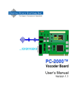
The AMBE-4020™-HDK is designed with flexibility in mind. It provides a variety of interfaces that allow
for fast and easy integration and testing.
The AMBE-4020™-HDK can be used as a standalone development tool or, be connected to another
AMBE-4020™-HDK via the UART channel interface to demonstrate its capabilities as a half-duplex
real-time communication system. With a PC, the board can encode speech data from the handset,
3.5mm stereo jack (Line In) input connections, or it can process speech files from a PC (USB
connection). When connecting two boards together the RS-232 UART interface acts as the channel for
the compressed voice serial data bit stream.
Figure 1 Basic block diagram of the AMBE-4020™-HDK board
DVSI Confidential Proprietary
Page 3
AMBE-4020™-HDK Development Board
User’s Manual Version 1.1
Section 2 – Connectors,
Test Points & Indicators
Board Connections
Item
Name
Connector Type
Description
P2
P3
P1
J7
J8
DC Line In
USB
Handset
Audio Output
Audio Input
Power Receptacle
Mini USB B SMT
RJ-11
3.5 mm Plug
3.5 mm Plug
P5
UART Serial Port
RJ-45
P4
Digital Handset
RJ-45
5 Volts DC
PC Connection
Full Duplex Communication
Speakers
Microphone
Packet Data (to/from AMBE4020™ Vocoder Chip)
Packet Data (to/from MSP)
Table 1 HDK Connectors
DVSI Confidential Proprietary
Page 4
AMBE-4020™-HDK Development Board
User’s Manual Version 1.1
Section 2 – Connectors,
Test Points & Indicators
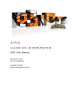
Figure 2 HDK Power, UART Serial Connection and PC USB Interface
2.2
2.2.1
HDK Power and Interface Connections
DC Power (P2)
The AMBE-4020™-HDK Development Board operates with a 5.0 V DC power supply. Simply plug in
the 120 V AC to 5.0 V DC (~1 A) power source (provided with the HKD) into an AC power source and
the DC power receptacle (P2)
Figure 3 DC Power 5V @ ~1 A
Figure 4 Power LEDs
2.2.2
RS-232 UART Connection
The RS-232 UART connection (P5) (RJ45 connector) on the HDK board is the Input/Output that can be
connected to another HDK board’s P5 connector for full duplex communications between two HDKs or it
can be used to interface to another device. The data transmitted or received consists of raw voice data,
DVSI Confidential Proprietary
Page 5
AMBE-4020™-HDK Development Board
User’s Manual Version 1.1
Section 2 – Connectors,
Test Points & Indicators
without any extra control data (other than start/stop bits and an "idle" period between voice frames). The
baud rate is determined by the vocoder bit rate selected, such that the "idle" period between voice
frames will be approximately 10 bits in duration.
To connect two HDK boards together via the RS-232 UART, the device EEPROM must be configured
for on of the “Dual-HDK” modes (RS232PTT, RS232ENC, or RS232DEC). Additionally switch the UART
switches (SW1 and SW2) to position 2 on only one of the two boards. Then connect a CAT 5
Standard Ethernet cable to each HDK board’ P5 connector to communicate. Each board converts the
input analog speech into digital speech samples, encodes the speech using the selected vocoder rate
and then sends the compressed bit stream out as serial data packets over the UART interface.
Simultaneously, the compressed bit stream from the other HDK are read in from the UART interface
and decoded back into digital speech samples. The decoded samples are converted back into analog
speech via the codec whose output is sent to both the handset and RCA line-level output connections.
2.2.3
USB PC Connection
The USB connection on the AMBE-4020™-HDK provides system setup, mode of operation and file I/O
via PC. Control and operation of the HDK Board is configured through the USB interface. To connect
the AMBE-4020™-HDK to a PC’s USB port, a USB “Type A to Mini-B” cable is required (included with
the HDK). To use the USB interface it is first necessary to install a USB driver. The USB connection is
interfaced to a UART on the K10 microcontroller via an FTDI USB to UART converter. The port settings
for this UART are 921,600 baud, 8-N-1, with hardware flow control. Note that there is not a direct
connection for packets from the PC to the AMBE-4020. All packets must be relayed through the K10
microcontroller.
The demo program, hdk4kclient.exe or hdk4kcontrol.exe, is used to control the AMBE-4020™-HDK via
the USB interface. These programs utilize the D2XX driver interface of the FTDI chip. The source code
for the demo programs is distributed with the HDK. Users may modify the code as needed to suit their
own application/test purposes. Note that the FTDI driver also exposes the HDK-4020 as a virtual COM
port to the PC. You can hook up a terminal emulator to the port and send test packets to the hardware.
DVSI Confidential Proprietary
Page 6
AMBE-4020™-HDK Development Board
User’s Manual Version 1.1
2.3
Section 2 – Connectors,
Test Points & Indicators
HDK Audio I/O
Figure 5 Board Audio Connections
2.3.1
P1 Handset
If a handset is used instead of the 2 wire interface, use a standard telephone handset to connect to the
RJ11 handset connector. Be sure that the handset cord is less than 12 inches long (included in the
optional accessories kit) when not stretched. This will prevent excessive noise from being introduced
into the voice signal. When the DAC interface is selected, the AMBE-4020™-HDK Development Board
always outputs the audio to both the 4-Wire and Handset output regardless of which voice source is
selected.
2.3.1.1
P1 Handset Analog Audio I/O
Handset I/O
Pin #
1
2
3
4
Signal Description
Connected to Ground
Connected to Ground
Speaker Out
Microphone In/DC Microphone Bias out
Table 2 Handset Pin out
2.3.2
3.5mm RCA Jacks
The AMBE-4020™-HDK Development Board provides two 3.5 mm jacks for the input and output of
analog mono audio. A typical analog audio input connection for the HDK would be to connect the audio
line output of an audio component such as, a digital tape player or even a PC sound card output to the
analog input jack (audio cables not included) of the AMBE-4020™-HDK Development Board. The
DVSI Confidential Proprietary
Page 7
AMBE-4020™-HDK Development Board
User’s Manual Version 1.1
Section 2 – Connectors,
Test Points & Indicators
AMBE-4020™-HDK Development Board outputs the analog signal on the output 3.5 mm jack that may
be connected to an amplifier or Audio In jack on a PC sound card. The unit always outputs the audio to
both the 4-Wire and Handset output regardless of the voice source selected.
2.3.3
J9 Header RCA Line-In or Handset Input Select
This jumper allows the user to select between the Line In (RCA 3.5mm plug) or the handset (RJ11)
analog audio I/O.
J9 (3x1 Header) RCA Line-In Handset Select
Jumper Installed Between Pins 1 - 2
Audio Source is Handset
Jumper Installed Between Pins 2 - 3
Audio Source is Line In
Table 3 J9 Codec Input Selection
Figure 6 Analog Audio IO Selection Jumper
2.3.4
Digital Handset
The AMBE-4020™ chip is designed to interface with the ADMP421 Omnidirectional Microphone from
IvenSense (http://www.invensense.com/mems/microphone/inmp421.html). The AMBE-4020™-HDK
provides a RJ45 connection for input from a digital microphone (see example circuit in the AMBE4020™ Vocoder Chip Users Manual). The digital mic interface provides a robust digital signal input that
helps demonstrate the versatility and superior performance of the AMBE-4020™ Vocoder. Along with
the DMIC_IN the RJ45 connection also provides access to the Push-to-Talk (PTT) switch and an analog
output that can be used to connect to an external earpiece.
DVSI Confidential Proprietary
Page 8
AMBE-4020™-HDK Development Board
User’s Manual Version 1.1
Section 2 – Connectors,
RJ45 Connector P4
Pin
Signal Name
Test Points & Indicators
Description
This is the output of the 1.92 MHz clock from the
AMBE-4020™ Vocoder Chip.
1
DMIC_CLK_OUT
2
Ground
3
DMIC_RX_DATA
4
1v8
5
PTT_HANDSET
6
7
8
Ground
ANALOG_OUT_SPEAKER
3v3A
The speech data from a digital microphone input
to the AMBE-4020™.
1v8 voltage connection
When this line is switched to ground through a
100 ohm resistor it enables the Push-To-Talk
feature of the AMBE_4020™ Vocoder Chip
Analog output signal with no gain.
3v3 voltage connection
Table 4 Digital Mic Connection
2.4
HDK Board Switches
Board Switches
Item Name
S1
Reset
S2
PTT Handset
SW1
SW2
UART CHAN1
UART CHAN2
Description
When pressed this switch resets the HDK board
This switch controls the Push-To-Talk feature of the
AMBE_4020™ Vocoder Chip.
When these two switches are in position 2 it crosses the output
connection of the UART to permit two HDK boards to
communicate without the need of a cross over cable. When
connection two HDK boards together only one of the HDK
boards need to set these two switches into position 2.
Table 5 HDK Switches
Figure 7 Switches SW1, SW2 and S1 (reset) S2 (Push-to-talk)
DVSI Confidential Proprietary
Page 9
AMBE-4020™-HDK Development Board
User’s Manual Version 1.1
2.5
Section 2 – Connectors,
Test Points & Indicators
HDK Headers
The HDK provides a variety of Headers, connections and jumpers (see Figure 1 Basic block diagram of
the AMBE-4020™-HDK board).
HDK Headers
Item
Header # of Pins
J1
Header 5x1
J2
Header 5x1
J3
Header 3x1
J5
Header 10x2
J9
Header 3x1
J10
Header 15x2
J11
Header 15x2
Name
PKT_TX PKT_RX PKT_CTS PKT_RTS
IFRAME / GFRAME
USB_UART_TX_DATA / USB_UART_RX_DATA
JTAG
Analog In or Handset
Daughter Card connection
Daughter Card connection
Table 6 HDK List of Headers
J1 (5x1Header)
Pins HDK Signal Name
5
1
PKT_TX_DATA
2
PKT_RX_DATA
3
PKT_CTS
4
PKT_RTS
Ground
AMBE-4020™ Signal Description
UART receive data. This is the input data signal for a
conventional UART using 8 data bits, no parity, and 1 stop bit
(8N1). Hardware flow control is used.
UART transmit data. This is the output data signal for a
conventional UART using 8 data bits. no parity, and 1 stop bit
(8N1). Hardware flow control is used.
Flow control output signal. The signal is low when the chip is
ready to receive data on UART_RX. The signal is high when the
chip is not ready to receive data on UART_RX. Sending data to
the chip when UART_RTS is high may result in errors.
Flow control input signal. When the signal is low the chip is
allowed to transmit data on UART_TX. When the signal is high
the chip stops transmitting data on UART_TX. Note that if
UART_CTS is set high while a transmission is in progress, data
flow will not be stopped until transmission of the current byte
completes.
Ground
Table 7 J1 Header Connections
J2 Header 3
Pin
Signal
1
DEBUG_TERM
2, 3
Ground
4
UART_CHAN1
5
UART_CHAN2
Description
Ground
Table 8 J2 Header
DVSI Confidential Proprietary
Page 10
AMBE-4020™-HDK Development Board
User’s Manual Version 1.1
Section 2 – Connectors,
J3 (3x1 Header)
Pins Signal
Description
1
2
3
Ground
USB Data to the PC
USB data from the PC
Ground
USB_UART_RX_DATA
USB_UART_TX_DATA
Test Points & Indicators
Table 9 J3 Header Connections
J5 (10x2 Header)
Pins
1
2
3,5,15,17,19
4
6
7,9,11,12,13,14,16,18,20
8
10
Signal
1v8
TMS
Ground
TCK
TDO
No Connect
TDI
SYS_RESETn
Description
Table 10 J5 Header Connections
UART Serial Port Pin Out
Pin
Number
1
2
3
Signal Name
HANDSET Input
ANALOG_IN_P
3mm RCA Jack Audio Input
Analog Audio Input Source for AMBE-4020™
ADC
Jumper Between
Jumper Between
Pins 1 and 2
Pins 2 and 3
HANDSET IN
3mm RCA JACK IN
Table 11 J9 Header Connections Analog Input Selection
2.5.1
Daughter Card Connections
J10 Daughter card connection
Pin #
I/O
Function Name
4
Input
CODEC_RESETn
8
Output
CODEC_CLK
12
Output
CODEC_FS
16
Input
CODEC_TX_DATA
19
Input
I2C0_SDA
DVSI Confidential Proprietary
Description
Output from the AMBE-4020™ Vocoder Chip to Reset
the external Codec on the daughter board.
Clock for external codec interface from the daughter
board input to the AMBE-4020™ Vocoder Chip
Frame Sync for the external codec interface from the
daughter board input to the AMBE-4020™ Vocoder
Chip.
PCM data for the external codec interface Output from
the AMBE-4020™ Vocoder Chip
This pin is the data pin used to transfer configuration
Page 11
AMBE-4020™-HDK Development Board
User’s Manual Version 1.1
23
Input
24
Output
I2C0_SCL
CODEC_RX_DATA
Section 2 – Connectors,
Test Points & Indicators
data to an external codec on the daughter board using
the I2C protocol.
This pin is the clock pin used in the transfer of
configuration data to an external codec using the I2C
protocol.
PCM data from the external codec interface Input to
the AMBE-4020™ Vocoder Chip
2, 6, 10, 14, 17, 18, 20, 21, 22, 25,
26, 27, 28, 29, 30
Digital Ground
1, 3, 5, 7, 9, 11, 13, 15
1.8 Volt Supply
Table 12 Daughter Board Connection J10
2.5.1.1
Daughter Board Connection J11
J11 Daughter card connection
Pin #’s
Function
Description
1, 3, 5, 7, ,9, 11, 13, 15, 17, 19, 21, 23, 25, 27, 29
Ground
Analog Ground
2, 4, 6, 8, 10, 12, 14, 16, 18, 20, 22, 24, 26, 28, 30
3v3
3.3 volts
Table 13 Daughter Board Connection J11
2.6
HDK Test Points
Test points allow the user to access the data to and from the AMBE-4020™ Vocoder Chip. By
connecting to these test points the user can monitor the data flow and to understand the operation of
the chip. For more detailed explanation of the I/O signal, refer to the AMBE-4020™ Vocoder Chip
Users manual.
HDK Board Header Test Points
Item
Name
Description
TP1
Reserved
TP2
Reserved
TP3
DEC
Monitor the AMBE-4020™ DEC signal
TP4
ENC
Monitor the AMBE-4020™ ENC signal
TP5
OFRAME
Monitor the AMBE-4020™ OFRAME signal
TP6
IFRAME
Monitor the AMBE-4020™ IFRAME signal
Table 14 Test Points
2.7
HDK Board Status Indicator LEDs
AMBE-4020™-HDK Development Board uses LEDs’ as a convenient way to display the current
condition of Audio I/O, vocoder and communications channel to the operator.
The LED indicators indicate the status of the HDK board as follows
DVSI Confidential Proprietary
Page 12
AMBE-4020™-HDK Development Board
User’s Manual Version 1.1
LED ID #
Description (when LED ON)
D1
D6
D11
D12
D19
D20
Vocoder Reset
Board Reset
3.3 V Power on
3.3 V Power on
Mode dependent
Mode dependent
Section 2 – Connectors,
Test Points & Indicators
Color (when LED ON)
Red
Red
Green
Green
Red
Red
Table 15 Board Status LED's
Figure 8 LED locations
2.8
Board Reset
When the AMBE-4020™-HDK reset switch is pressed the HDK goes through the following sequence:
1. The K10 microcontroller boots up initially into USB packet mode. The K10 UARTs are
initialized, the AMBE-4020™ is reset and communication between the K10 and AMBE-4020™
is established. The HDK is ready to receive packets via the USB interface after it sends an
HDK_READY packet.
2. If no packets are received via the USB interface within the first 250 ms after reset, then the K10
microcontroller will access the configuration data stored into its on-chip EEPROM and use it
configure the board. This facilitates stand-alone dual-HDK operation (no PC required). The
EEPROM can be configured using the hdk4kcontrol.exe GUI program.
DVSI Confidential Proprietary
Page 13
AMBE-4020™-HDK Development Board
User’s Manual Version 1.1
Section 2 – Connectors,
Test Points & Indicators
Figure 9 Reset Switch S1
Figure 10 Reset LEDs
DVSI Confidential Proprietary
Page 14
AMBE-4020™-HDK Development Board
User’s Manual Version 1.1
HDK Configuration
3 HDK Configuration
Digital Voice Systems, Inc.
The Speech Compression Specialists
3.1
Overview
The AMBE-4020™-HDK Board is ideal for encoding and decoding speech. Simply connect the AMBE4020™-HDK Board to a Windows based PC’s USB interface, configure vocoder rate and options then
encode and decode files or process real time speech. The AMBE-4020™-HDK Board can play a key
role in the development of communication systems that incorporate the AMBE-4020™ vocoder chip.
The AMBE-4020™-HDK Board incorporates a USB to serial UART Integrated Circuit Device
manufactured by FTDI (P/N FT232R). This allows designers to utilize FTDI’s off-the-shelf drivers
(compatible with several operating systems) for application customization and flexibility. The AMBE4020™-HDK Board is configured to use the USB drivers offered by FTDI. Visit the FTDI website at
http://www.ftdichip.com/FTDrivers.htm for more information.
3.2
USB Driver installation
To begin using the AMBE-4020™-HDK Board connect it to an available USB port on the computer and
install the required FTDI drivers. These drivers are downloaded automatically set up the AMBE4020™-HDK Board to communicate on the PC’s serial COM port. The AMBE-4020™-HDK Board has
drivers available for both Windows-32 bit and Windows-64 bit operating systems. The drivers must be
installed the first time a new AMBE-4020™-HDK Board is connected to the PC. Once the driver is
installed Windows will automatically re-load the driver each time the AMBE-4020™-HDK Board is reconnected.
3.2.1
Driver installation example for Windows 7.
Connect the AMBE-4020™-HDK Board to an available USB port on the PC. Windows 7 indicates it is
beginning to install the driver.
Figure 11 Installing driver software indicator
Windows 7 begins driver installation. Windows 7 then finishes installing the driver for the COM port and
displays the software for this device has been successfully installed.
Click “X” to close the balloon.
DVSI Confidential Proprietary
Page 15
AMBE-4020™-HDK Development Board
User’s Manual Version 1.1
HDK Configuration
Figure 12 AMBE-4020™-HDK Board drivers are installed and ready to use
To verify the drivers are installed and find out which COM port it was assigned use Windows’ Device
Manager. To open Windows “Device Manager“
Click “Start”, click “Run”, and then type "devmgmt.msc" (without the quotation marks). Alternatively,
open the Device Manager (located in "Control Panel\System" then select the "Hardware" tab and click
"Device Manger") and select "View > Devices by Type", the USB Serial device should appear under
Ports (COM & LPT)" as USB Serial Port (COMXX) where “XX” is the port number of the USB interface.
Figure 13 Windows Device Manager showing the AMBE-4020™-HDK on COM 15
DVSI Confidential Proprietary
Page 16
AMBE-4020™-HDK Development Board
User’s Manual Version 1.1
HDK Configuration
Note: Write down the Com Port that is being used for the USB Driver, this value will be required to run
the AMBE-4020™-HDK Board USB control program. In Figure 13 the COM port is shown as COM15.
NOTE: If the Device is shown with a yellow exclamation point then the USB driver is not
completely installed. To fix this, uninstall the Device, disconnect the AMBE-4020™-HDK
Board from the PC’s USB port and then reconnect the AMBE-4020™-HDK Board to the PC’s
USB port and allow MS Windows to find new hardware. Then follow the instructions to
reinstall the device.
DVSI Confidential Proprietary
Page 17
AMBE-4020™-HDK Development Board
Operation
User’s Manual Version 1.1
4 Operation
Digital Voice Systems, Inc.
4.1
Operating Modes
The Speech Compression Specialists
The HDK provides different operating modes to allow testing and evaluation of data to and from the
AMBE-4020™ vocoder chip at various stages along the data path. This gives the user the opportunity
to understand how the AMBE-4020™ vocoder chip needs to be implemented and how to use the HDK
as a tool to verify a new design.
4.2
HDK Software
The AMBE-4020™-HDK Vocoder board is set-up, controlled and operated from a PC. The board can
also be configured to boot into a particular mode for stand alone operation see section 4.6
HDK4kcontrol.exe User Interface. In order for the PC to work with the HDK a USB cable must be used
and USB drivers must be installed. See the USB PC Connection Section on how to install the USB
drivers. Once the connection between the PC and the HDK is established the HDK software should be
installed on the PC.
The AMBE-4020™-HDK Development Board kit includes a CD with a PC executable programs
(hdk4kclient.exe, dvsiserver32.exe, hdk4kcontrol.exe). These programs should be copied from the CD
into a user created directory located on a C-drive named C:\HDK-4020-R001. The executable
programs enable the user to record audio input from various sources to a file, play out encoded files to
various outputs, encode and decode file to file or just simply passthru an audio source, as well as, set
up an HDK to HDK communication link.
The HDK can be controlled via a command line executable (hdk4kclient.exe) in a COMMAND PROMPT
window or by using the provided GUI interface executable (hdk4kcontrol.exe). The DVSI Vocoder
Device Server executable (dvsiserver32.exe) must be started prior to running either of these two
programs.
4.2.1
Installing HDK program files On Windows
Step 1 Create a folder named C:\HDK-4020-R001 on the PC.
Step 2 Copy the entire contents of the CD provided with the HDK into this folder.
Step 3 When the copying of all the contents is finished go to the C:\HDK-4020-R001 directory and
unzip tv.zip file to C:\HDK-4020-R001\tv. This compressed data file contains test vectors that may be
used for vocoder testing.
Step 4 Before continuing on review all of the documentation in the C:\HDK-4020-R001\Docs
directory.
Step 5 Verify correct operation of the board by using the hdk4kclient.exe program as described in
section 4.4 Hdk4kclient.exe program.
Also included on the HDK CD disk are sample speech and compressed speech files. The tv.zip file has
three test vectors in various formats, data rates, without/with bit errors and hard/soft decision decoding.
The files supplied in the root directory of the tv.zip file are the original test vector files named and
formatted as follows:
clean.dat, dam.dat and irstia.dat --- are 16 bit pcm audio files sampled at 8kHz.
clean.a, dam.a and irstia.a --- are 8 bit a-law audio files sampled at 8kHz.
clean.µ, dam.µ and irstia.µ --- are 8 bit µ-law audio files sampled at 8kHz.
DVSI Confidential Proprietary
Page 18
AMBE-4020™-HDK Development Board
Operation
User’s Manual Version 1.1
The 52 file folders in the root directory of the tv.zip file contain these three files, processed at the index
rate as indicated by the folder name. For example, folder named “0” contains files processed at rate
index 0.
Inside each of these numbered folders “X” are sub directories that contain processed files in various
formats, without/with bit errors and hard/soft decision decoding (see Table 16 Folder description). The
base of the numbered directory “X” has files encoded (clean.bit, dam.bit and irstia.bit) and decoded
(clean.dat, dam.dat and irstia.dat) at the index rate of the numbered directory from the original pcm files
in the root directory.
Sub-Directories under numbered
Folder “X”
Processed
file format
Number of
Gaussian bit
errors
Hard or Soft
Decision Decoding
C:\HDK-4020-R001\tv\”X”\a
C:\HDK-4020-R001\tv\”X”\G01-1
C:\HDK-4020-R001\tv\”X”\G01-4
C:\HDK-4020-R001\tv\”X”\G02-1
C:\HDK-4020-R001\tv\”X”\G02-4
C:\HDK-4020-R001\tv\”X”\G05-1
C:\HDK-4020-R001\tv\”X”\G05-4
C:\HDK-4020-R001\tv\”X”\G10-1
C:\HDK-4020-R001\tv\”X”\G10-4
C:\HDK-4020-R001\tv\”X”\u
a-law
pcm
pcm
pcm
pcm
pcm
pcm
pcm
pcm
µ-law
0
1%
1%
2%
2%
5%
5%
10%
10%
0
1-bit Hard decision
1-bit Hard decision
4-bit Soft Decision
1-bit Hard decision
4-bit Soft Decision
1-bit Hard decision
4-bit Soft Decision
1-bit Hard decision
4-bit Soft Decision
1-bit Hard decision
Table 16 Folder description
The “a” and “u” are sub-folders that contain the encoded (clean.bit, dam.bit and irstia.bit) and the
decoded (clean.dat, dam.dat and irstia.dat) at the index rate of the numbered directory from the original
8 bit a-law and µ-law audio files sampled at 8kHz.
All sub-directories named “a” contain the encoded file data (clean.bit, dam.bit and irstia.bit) from the
original a-law test vector file. These compressed speech files were encoded (recorded) at a data rate
as indicated by the rate index number “X” of the higher level directory. The folder also contains the
decoded data files (in pcm format) clean.dat, dam.dat and irstia.dat from these encoded files, as well as
the converted a-law files (clean.a, dam.a and irstia.a) from the decoded dat files.
All sub-directories named “u” contain the encoded file data (clean.bit, dam.bit and irstia.bit) from the
original µ-law test vector file. These compressed speech files were encoded (recorded) at a data rate
as indicated by the rate index number of the higher level directory. The folder also contains the
decoded data files (in pcm format) clean.dat, dam.dat and irstia.dat from these encoded files, as well as
the converted µ-law (clean.u, dam.u and irstia.u files from the decoded dat files.
All sub-directories named “g” contain the encoded file data (dam.bit) from the original pcm test vector
file. The compressed speech file was encoded (recorded) at a data rate as indicated by the rate index
number of the higher level directory with Gaussian bit errors. The number of bit errors is indicated by
the number following the “g” as follows:
g01 = 1% bit errors
g02 = 2% bit errors
g05 = 5% bit errors
g10 = 10% bit errors
The number after the bit error identifier is either a “-1” or a “-4” this indicates that the files were
processed with 1 bit hard decision or 4 bit soft decision decoding.
DVSI Confidential Proprietary
Page 19
AMBE-4020™-HDK Development Board
User’s Manual Version 1.1
Operation
In addition to the sample files, there are three executable files and several sample scripts to facilitate
testing operations.
4.3
Dvsiserver32.exe program
The DVSI server program (dvsiserver32.exe) is used to establish a link between the PC and the
connected HDK devices. This program must be running before starting either hdk4kclient.exe or
hdk4kcontrol.exe programs. To run dvsiserver32.exe , double click on the executable. When the
program starts it will poll the USB ports to find any connected HDK devices each one will then be listed
in the window opened by the program. For information about each of the connected device just hover
the mouse over the device serial number in the window.
Dvsiserver32.exe effectively translates the D2XX driver interface of the HDK into a message pipe. To
communicate with any device, a client program simply opens a message pipe to the device and sends
packets through the message pipe. The server can establish a connection to many devices and can
expose these devices to clients upon request. The server takes care of all the hardware details such as
setting up the baud rate, flow control, timeouts, etc.
4.4
Hdk4kclient.exe program
The hdk4kclient.exe program is written entirely in C to facilitate easy modification by customers. The
software is compact, yet includes all necessary code to arrange the channel packet protocol and
communicate with the HDK through the dvsiserver executable program. The source code for the
hdk4kclient.exe program is provided as an example to assist in the creation custom programs. This
software sets up and operates the HDK to demonstrate useful features of the AMBE-4020™ Vocoder
Chip and is a good reference to use as a starting point for more complex designs tailored to specific
needs.
The HDK can be set up and controlled using a command prompt window and a command line interface
program “hdk4kclient.exe”. The hdk4kclient program can be used to record audio input from various
sources (ADC, AIC14, DMIC) to a file, play out encoded files to various outputs (DAC or AIC14),
encode/decode file to file or just simply passthru an audio source between the audio in to the audio out.
DVSI Confidential Proprietary
Page 20
AMBE-4020™-HDK Development Board
User’s Manual Version 1.1
Operation
Before starting the program an HDK device must be connected to the PC and the dvsiserver program
(dvsiserver.exe) must be started. To run the hdk4kclient.exe program, open a command prompt
window and change to the directory (C:/HDK-4020-R001/bin) that has the hdk4kclient.exe program file
in it and type in the desired command. Alternatively the directory C:/HDK-4020-R001/bin may be added
to your “PATH” environment variable.
4.4.1
C:\
Example 1: Encoding a speech file using hdk4kclient.exe
Command Prompt
-
X
hdk4kclient.exe –r 40 -enc –bs 230400 ../tv/dam.dat output.bit
Figure 15 Encoding a speech file using hdk4kclient.exe
This example uses the HDK-4020 to encode the speech file, ../tv/dam.dat (example speech data
provided with the HDK-4020), using AMBE-4020™ rate index 40 (4000 bps voice rate with no FEC).
The compressed speech data is written to a file named “output.bit”. The baud rate used for
communication between the K10 microntroller and the AMBE-4020™ is 230400. The AMBE-4020™ is
operated in packet mode for this command. Note that for real time operation in packet mode, a baud
rate of at least 172800 is required.
4.4.2
C:\
Example 2: Recording from AMBE-4020™ on chip ADC using hdk4kclient.exe
Command Prompt
-
X
hdk4kclient.exe –r 0 -enc –seconds 10 adc record.bit
Figure 16 Recording from ADC using hdk4kclient.exe
This example uses the HDK-4020 to record 10 seconds of compressed speech data to the file
“record.bit”. The AMBE-4020™ rate index 0 (2400 bps with no FEC) is selected. The source for the
speech data is the AMBE-4020™’s on chip ADC. The AMBE-4020™ is operated in codec mode. Note
that rather than specifying an input file name, as in example 1, “adc” was specified as the input source.
Hdk4kclient.exe recognizes “adc”, “dmic”, “i2sl” and “i2sh” as codec mode input sources. When
specified, they request that the AMBE-4020™ is operated in codec mode and that the codec source
data is obtained from the AMBE-4020™’s on chip ADC, the AMBE-4020™’s digital microphone input, or
the AIC14’s line-in or handset port of the optional codec daughter card. When the input name does not
match one of these special names, the AMBE-4020™ is operated in packet mode, with speech data
obtained from a file.
DVSI Confidential Proprietary
Page 21
AMBE-4020™-HDK Development Board
User’s Manual Version 1.1
4.4.3
C:\
Operation
Example 3: Decoding a channel file using hdk4kclient.exe
Command Prompt
-
X
hdk4kclient.exe –r 40 -dec –bs 230400 output.bit output.dat
Figure 17 Decoding a channel file using hdk4kclient.exe
This example uses the HDK-4020 to decode the channel file, output.bit, which was produced in
example 1. Note that the rate index selected must match the rate index used in example 1 (40 in this
case). The decoded speech data is written to a file named “output.dat”. The baud rate used for
communication between the K10 microntroller and the AMBE-4020™ is 230400. The AMBE-4020™ is
operated in packet mode for this command. Note that for real time operation in packet mode, a baud
rate of at least 172800 is required.
4.4.4
C:\
Example 3: Playing a channel file to the AMBE-4020™ on chip DAC using
hdk4kclient.exe
Command Prompt
-
X
hdk4kclient.exe –r 40 -dec –bs 230400 output.bit dac
Figure 18 Playing a channel file to the AMBE-4020™ DAC using hdk4kclient.exe
This example is similar to example 3, except that instead of writing the decode speech data to a file, it is
played out on the AMBE-4020’s on chip DAC. The AMBE-4020™ is operated in codec mode. Note
that rather than specifying an output file name as in example 3, “dac” was specified instead.
Hdk4kclient.exe recongnizes two special output sources: “dac” and “i2s”. When specified, they indicate
that speech output should be played out through the specified codec interface rather than being written
to a speech file. They also request that the AMBE-4020™ is operated in codec mode rather than
packet mode.
*Note: Before running hdk4kclient.exe be sure that the dvsiserver32.exe program is running.
4.4.5
More hdk4kclient.exe options
We have introduced hdk4kclient using a few examples, but hdk4kclient.exe supports more advanced
options. This section will provide more details about the hdk4kclient.exe command line options.
hdk4kclient.exe supports the following generic command line formats.
hdk4kclient -enc [options] [input file name] [output file name]
hdk4kclient -dec [options] [input file name] [output file name]
hdk4kclient -version
hdk4kclient -rboot [1-3] [rboot file name]
hdk4kclient -wboot [1-3] [wboot file name]
DVSI Confidential Proprietary
Page 22
AMBE-4020™-HDK Development Board
User’s Manual Version 1.1
Operation
the options available are as follows:
-alaw
-be <baud rate>
-break
-bs <baud rate>
-dec
-dec -sdbits 1
-dec -sdbits 4 or -decsd
-dgain G
-dtx N
-egain G
-enc
[input file name]
-lpme <power mode>
-lpms <power mode>
-n [serial number]
-noparity
-ns 0
[output file name] or -cmp [compare file name]
-passthru
-q
-r R or -r 0xNNNN 0xNNNN 0xNNNN 0xNNNN 0xNNNN 0xNNNN
-rboot N rbootname
-reset
-seconds S
-skew M
-tone Idx Amp
-ulaw
-version
-wakects
-wakerx
-wboot N wbootname
Table 17 hdk4kclient.exe options
4.4.6
hdk4kclient.exe options descriptions
-enc
Specifies an encode operation. If [input file name] is the name of a file, then the AMBE-4020™
is operated in packet mode. If [input file name] is either "adc", "dmic", "i2sl", or "i2sh", then the
AMBE-4020™ is operated in codec mode.
-dec
Specifies a decode operation. If [output file name] is the name of a file or if -cmp [compare file
name] is specified, then the AMBE-4020™ is operated in packet mode. If [outut file name] is
either "dac" or "i2s", then the AMBE-4020™ is operated in codec mode.
[input file name]
When the encoder is specified (-enc option), [input file name] is the file from which the speech
input data data is obtained. If "adc", "dmic", "i2sh", or "i2sl" are secified in place of a file name
they are treated specially. They each indicate that the AMBE-4020™ is operated in codec
DVSI Confidential Proprietary
Page 23
AMBE-4020™-HDK Development Board
User’s Manual Version 1.1
Operation
mode and specify the codec source. Note that "dmic" requires that a digital microphone is
attached to P4. "i2sh" or "i2sl" require the optional codec daughter card. "i2sh" selects the
handset input on the daugter card wheras "i2sl" selects the line input.
When the decoder is specified (-dec option), [input file name] is the file from which the
compressed speech data data is obtained.
[output file name] or -cmp [compare file name]
When the encoder is specified (-enc option), [output file name] is the name of the file in which
the compressed voice data will be stored.
When the decoder is specified (-dec option), [output file name] is the name of the file in which
the decoded speech data will will be stored. If "dac" or "i2s" are specified in place of a file name
they are treated specially. They each indicate that the AMBE-4020™ is operated in codec
mode and select the codec that receives the output. "dac" specifies that the output goes to the
AMBE-4020™'s on chip DAC. "i2s" specifies that the output goes to the AIC14 on the optional
codec daughter card via the AMBE-4020™'s I2S inerface.
If -cmp [compare file name] is specified instead of simply an output file name, then hdk4kclient
does not store the results in a file. Instead, it compares the produced output to the expected
output which is contained in the file [compare file name]. This option is useful for testing
purposes.
-version
This should be specified without any other options. It will send a packet to the AMBE-4020™ to
query its product ID and version strings. The resulting strings are displayed.
-q
Causes the program to be less verbose. Less stuff is displayed.
-n [serial number]
Hdk4kclient addresses the HDK-4020 whose serial number matches [serial number]. This is
useful in cases where multiple HDK-4020s are attached to the computer, but it is desired to
address a particular HDK-4020. Note that the serial numbers of available HDK-4020s are
displayed within the dvsiserver32.exe window. If this option is not specified, then hdk4kclient
addresses any available HDK-4020.
-bs <baud rate>
Specifies the initial baud rate used.
A packet is sent to the HDK-4020 to change the baud rate used by the UART that connects the
K10 microcontroller to the AMBE-4020™. Note that the baud rate used at the FTDI to K10
microcontroller is always 921600 baud. The baud rate is changed before any other packets are
sent to the AMBE-4020™.
Typical baud rates are 57600, 115200, 230400, 460800 and 921600, but any value ≤ 921600
can be specified as long as it provides enough through put for the data that must flow.
Typically, baud rates of 172800 or higher are used for packet mode due to the larger size of
speech packets.
DVSI Confidential Proprietary
Page 24
AMBE-4020™-HDK Development Board
User’s Manual Version 1.1
Operation
Typically baudrates ≤ 115200 baud should be used for codec mode in order to conserve power.
Using a large baud rate during packet mode allows processing at a rate that slightly exceeds
real time.
-be <baud rate>
Specifies the baud rate used after processing the vector.
Prior to exiting, but before setting the final power mode (see –lpme), the baud rate can be
changed. This is typically used in conjunction with –lpme to reduce the baud rate prior to
entering a lower power mode.
-lpms <power mode>
Specifies the power mode that is entered at the start of the command.
The power mode of the AMBE-4020™ is set as specified by sending PKT_PMODE (see AMBE4020™ User’s Manual). When power mode is 0, 1, or 2 then the AMBE-4020™ operates at full
power, although it still consumes little power when no packets are being sent or received.
<power mode>=1 or 2 do not have any use in conjunction with hdk4kclient, since they specify
how power is conserved during push-to-talk codec mode. In packet mode or in codec mode
<power mode>=1 or 2 behave the same as <power mode>=0.
-lpms 3 will transition the AMBE-4020™ to Low Power Packet Mode. Note that the baud rate
must be ≤ 125000 baud prior to entering Low Power Packet Mode, therefore –lpms 3 should be
used in conjunction with –bs 115200 (or lower). Packets will be processed in packet mode at a
very slow rate since the AMBE-4020™ clock rate is reduced. Do not specify codec mode
operation in combination with –lpms 3.
Do not use <power mode> = 4 or 5 here. Power reduction is intended to be used at the end of
a command via –lpme.
-lpme <power mode>
Specifies the power mode that is entered at the end of the command.
The power mode of the AMBE-4020™ is set as specified by sending PKT_PMODE (see AMBE4020™ User’s Manual). PKT_PMODE is sent to the AMBE-4020™ after processing the
speech data just prior to the time that hdk4kclient exits.
-lpme 3 will transition the AMBE-4020™ to Low Power Packet Mode. Any subsequent
hdk4kclient invocation can use –lpms 0, -lpms 1, –lpms 2 or
–reset, after which the AMBE-4020™ will return to Packet Mode operation. Note that the baud
rate must be ≤ 125000 baud prior to entering Low Power Packet Mode, therefore –lpme 3
should be used in conjunction with –bs 115200 (or lower).
-lpme 4 will transition the AMBE-4020™ to Sleep Mode. Any subsequent hdk4kclient invocation
must use –wakects, -wakerx, or –reset after which the AMBE-4020™ will return to packet mode
operation. Note that the baud rate must be ≤125000 baud prior to entering Low Power Packet
Mode, therefore –lpme 3 should be used in conjunction with
–be N, where N ≤125000. Note that the AMBE-4020™ consumes less power in Sleep Mode,
but it cannot receive any packets until it returns to Packet Mode. Upon receiving a transition on
the UART_CTS pin (achieved using –wakects) or a wake byte on the UART_RX pin (achieved
using –wakerx), the AMBE-4020™ will return to Packet Mode, and any prior settings will be
retained. Another way of returning to packet mode is to issue a hard reset (achieved using –
reset), but this takes longer and results in prior settings being lost, meainging that the AMBE-
DVSI Confidential Proprietary
Page 25
AMBE-4020™-HDK Development Board
User’s Manual Version 1.1
Operation
4020™ would need to be reconfigured. No packets can be processed in Sleep Mode, but the
AMBE-4020™ can be readies for operation quickly.
-lpme 5 will transition the AMBE-4020™ to Halt Mode. Any subsequent hdk4kclient invocation
must use –reset after which the AMBE-4020™ will return to packet mode operation. Halt Mode
is the AMBE-4020™’s lowest power mode, but it can not process any packets and requires a
reset before operation can resume.
-wakects
This option can be used when the AMBE-4020™ is known to be in Sleep Mode and it is
necessary to wake it prior to performing the command specified by the remainder of the
command line. It results in a pulse (high then low) being sent to the AMBE-4020™ UART_CTS
pin. This wakes the AMBE-4020™ from sleep mode. The wake occurs prior to attempting to
send any other packets.
Only one (or fewer) option from the set { -wakects, -wakerx, -reset, -break } may be used on
any hdk4kclient command line.
-wakerx
This option can be used when the AMBE-4020™ is known to be in Sleep Mode and it is
necessary to wake it prior to performing the command specified by the remainder of the
command line. It results in a wake byte (0xFF) being sent to the AMBE-4020™ UART_RX pin.
This wakes the AMBE-4020 from sleep mode. Note that a wake byte has the start bit low and all
other bits high such that it is a single low pulse on the UART_RX pin. The wake occurs prior to
attempting to send any other packets.
Only one (or fewer) option from the set { -wakects, -wakerx, -reset, -break } may be used on
any hdk4kclient command line.
-reset
This option can be used at any time to request that the AMBE-4020™ is reset prior to
performing that actions specified by the remainder of the command. Reset is required when the
AMBE-4020™ is in halt mode (due to prior use of –lpme 5).
Only one (or fewer) option from the set { -wakects, -wakerx, -reset, -break } may be used on
any hdk4kclient command line.
-break
This option resets the AMBE-4020™ by sending a “break” signal on UART_RX. This in turn
causes the AMBE-4020™ to issue a soft reset. The break signal on UART_RX is not sufficient
to wake the AMBE-4020™ from Halt Mode.
Only one (or fewer) option from the set { -wakects, -wakerx, -reset, -break } may be used on
any hdk4kclient command line.
-egain G
Specify encoder gain.
-egain G may be used in conjunction with –enc for either codec mode or packet mode to specify
a gain in dB to be applied by the encoder. When not specified, the default gain is 0 dB. -20 ≤ G
≤ 20.
DVSI Confidential Proprietary
Page 26
AMBE-4020™-HDK Development Board
User’s Manual Version 1.1
Operation
-dgain G
Specify decoder gain.
-dgain G may be used in conjunction with –dec for either codec mode or packet mode to specify
a gain in dB to be applied by the decoder. When not specified, the default gain is 0 dB. -20 ≤ G
≤ 20.
-noparity
By default all packets sent to the AMBE-4020™ have parity bytes enabled. When this option is
used, parity bytes are disabled at the start of the command and then re-enabled at the end.
-seconds S
When encoding in codec mode, the default record duration is 15 seconds. This option changes
the record duration to S seconds.
-r R or -r 0xNNNN 0xNNNN 0xNNNN 0xNNNN 0xNNNN 0xNNNN
Specify the vocoder bit rate.
This option is used in conjunction with –enc or –dec.
By default the AMBE-4020™ vocoder rate index selected is index 32 (3600 bps voice + 2800
bps FEC = 6400 bps total). –r R allows any other rate index to be selected. See AMBE-4020™
User’s Manual for more information about available rate indices.
Additional custom rates may be selected by specifying six 16-bit rate words using the format
shown.
-passthru
Specify passthru codec mode.
Passthru mode allows speech samples stored in a file to be played out directly to a codec.
Passthu mode also allows samples recorded from a codec to be stored directly to a file without
coding.
Examples:
1. hdk4kclient -dec –passthru speech.dat dac
speech in the file speech.dat is played out on the AMBE-4020™ on chip DAC.
2. hdk4kclient –enc –passthru adc speech.dat
speech obtained from the AMBE-4020™ on chip ADC is saved in the file speech.dat.
-passthru should not be used in conjunction with packet mode.
-ns 0
Disable the AMBE-4020™ noise suppressor.
DVSI Confidential Proprietary
Page 27
AMBE-4020™-HDK Development Board
User’s Manual Version 1.1
Operation
This option is used in conjunction with –enc.
By default the AMBE-4020™ noise suprressor is enabled. Using –ns 0 disables the noise
suppressor.
-dec -sdbits 1
Specify hard-decision decoding.
The channel data input to the decoder uses hard-decision format, where each byte contains 8
hard-decsion bits.
-dec -sdbits 4 or -decsd
Specify soft-decision decoding.
The channel data input to the decoder uses soft-decision format, where each byte contains 2 4bit soft-decsion bits.
-alaw
Specify a-law companding.
When used in conjunction with –enc, the speech data in the input speech file are assumed to
contain a-law compressed samples.
When used in conjunction with –dec, the speech data in the output speech file will be a-law
compressed.
Used with packet mode only.
-ulaw
When used in conjunction with –enc, the speech data in the input speech file are assumed to
contain u-law compressed samples.
When used in conjunction with –dec, the speech data in the output speech file will be u-law
compressed.
Used IN packet mode only.
-rboot N rbootname
Read boot configuration N from AMBE-4020™ EEPROM.
1 ≤N ≤3
The boot configuration data for the specified boot configuration is output to the file rbootname in
binary format.
-wboot N wbootname
Write to boot configuration N in the AMBE-4020™ EEPROM.
1 ≤N ≤3
DVSI Confidential Proprietary
Page 28
AMBE-4020™-HDK Development Board
User’s Manual Version 1.1
Operation
The boot configuration data in the file wbootname is written to the specified boot configuration
within the AMBE-4020™ EEPROM.
-tone Idx Amp
Force transmission or generation of a tone.
When used in conjunction with –enc, the encoder is forced to transmit channel data
representing a tone with the specified tone index and amplitude. Note that not all vocoder rates
support in-band tone signaling for all tone types (see AMBE-4020™ User’s Manual). The
quality is lower for tones that are not supported via in-band signaling.
When used in conjunction with –dec, the decoder is forced to synthesize the specified tone. Inband signaling is not required for this feature, therefore all tones are fully supported by all
vocoder rates.
-skew M
Enable skew control and specify IFRAME clock rate.
This option is used in conjunction with codec mode. When specified, skew control is enabled
and the IFRAME clock rate is specified via M, where
IFRAME_Hz = 3.125 MHz / M
such that when M=62500, IFRAME_Hz = 50 Hz. Small adjustments to M allow slight
adjustments to the IFRAME frequency. 48.75 < IFRAME_Hz < 51.25. This will slightly alter the
rate at which the HDK-4020 transmits voice frames. It also alters the rate at which it decodes
frames. The decoder can compensate for cases where it receives frames at a different rate
than it decodes them, by inserting or deleting a frame as necessary. This is known as a frame
slip or a frame erasure. Infrequent slips or erasures do not significantly effect voice quality.
The IFRAME signal is generated by the K10 microcontroller. This option causes a special
packet to be sent to the HDK-4020 causing the K10 microcontroller to change the frequency of
IFRAME.
-dtx N
Enable Discontinuous Transmission (DTX) simulation.
When DTX is enabled in conjunction with –enc the bits for certain silence frames are replaced
with all ones. Replacing the channel data with all ones is used to simulate frames that are not
transmitted. N controls how frequently silence frames are “transmitted”. N = 0, indcates that
silence frames are always transmitted, N = 1, indicates that every other silence frame is
“transmitted”, N =2, indicates that every third silence frame is “transmitted”. N = 9999, indicates
that every 10000th silence frame is “transmitted”. N = 10000, is a special case where silence
frames are never “transmitted”.
When N ≥ 0 is enabled in conjunction with –dec, the DTX simulation is enabled at the decode
side. Before decoding a frame of bits, first a check is made to see if the frame of bits is all
ones. If the frame is all ones then the decoder sets the CNI flag, indicating that no channel data
was received such that the decoder should generate comfort noise. If the frame does not
contain all ones, then it is passed to the decoder for normal decoding and the CNI flag is not
set.
Note that the DTX simulation is implemented in the microcontroller software.
DVSI Confidential Proprietary
Page 29
AMBE-4020™-HDK Development Board
User’s Manual Version 1.1
4.5
Operation
Connecting two HDK’s together
The AMBE-4020™ HDK can be directly connected to a second AMBE-4020™ HDK using the UART
channel interface (P5). This physical link establishes a real-time, half-duplex communication
connection between the two units. The connected HDKs can be run in either of two configurations
The HDK Board implements an asynchronous UART serial interface for channel data using a protocol
designed by DVSI.
4.5.1
Half Duplex Communication Setup and Control
To set up a half duplex communication link between two HDK boards, each board must be individually
configured and then the connection (P5 to P5) between the two boards can be made using a standard
CAT5 Ethernet cable. In order for two boards (board “HDK#1” to connect to board “HDK#2”) one board
(board ”HDK#1”) has to switch both SW1 and SW2 to position 2 and the other board (board “HDK#2”)
leaves the switches in position 1. Both boards “HDK#1” and “HDK#2” must be set to the same vocoder
rate.
Figure 14 SW1 and SW2 (shown in Position 1)
4.5.2
Configuration 1 --- HDK#1 in RS232ENC Mode to HDK#2 in RS232DEC Mode
The analog voice from the first HDK#1 Board is encoded and sent across the serial interface to the
second HDK#2 Board where the incoming channel packets get decoded and played out on the selected
audio output of the second HDK Board.
DVSI Confidential Proprietary
Page 30
AMBE-4020™-HDK Development Board
User’s Manual Version 1.1
Operation
Figure 15 HDK1 in RS232ENC Mode
Figure 16 HDK#2 in RS232DEC Mode
4.5.3
Configuration 2 --- HDK#1 in PTT Mode to HDK#2 in PTT Mode
--- directly connects two AMBE-4020™ HDK’s together using the UART channel interface (P5).Either
AMBE-4020™-HDK Vocoder board can encode speech from its analog input and send the encoded
packet across the serial channel to be decoded by first AMBE-4020™-HDK Development Board. Each
board can select either the handset or line-in or DMIC input as the audio source. When the PTT switch
(S2) is pressed the selected analog source is encoded and sent across the serial interface to the
connected HDK Board where the incoming channel packets get decoded and played out on the
selected audio output of the second HDK Board.
DVSI Confidential Proprietary
Page 31
AMBE-4020™-HDK Development Board
User’s Manual Version 1.1
Operation
Figure 17 Both HDK#1 and HDK#2 in RS232PPT Mode
Figure 18 Transmit and Receive LEDs
4.6
HDK4kcontrol.exe User Interface
DVSI provides a GUI interface software (hdk4kcontrol.exe) that is used along with the DVSI server
program (dvsiserver32.exe) for a fast and easy way to configure and control each HDK in an HDK to
HDK communication link.
DVSI Confidential Proprietary
Page 32
AMBE-4020™-HDK Development Board
User’s Manual Version 1.1
Operation
Figure 19 Control Software window
Prior to launching hdk4kcontrol.exe make sure dvsiserver32.exe is running. Then launch
hdk4kcontrol.exe by clicking on its icon or a shortcut to it. Menu controls are disabled until you select
an available HDK-4020 device (via its serial number) and then click the “Connect” button. Upon
successful connection, product name and version information will be displayed within the HDK Device
box, the “Connect/Disconnect” button will now display “Disconnect” and the remaining Menus become
enabled.
Upon establishing a connection to the HDK-4020, hdk4kcontrol.exe will obtain the menu settings from
the HDK’s EEPROM. The user may change any of the menu items to effect the current configuration of
the HDK. Doing so causes packets to be sent (immediately) to the HDK to achieve the requested
configuration. Any time the HDK’s current configuration differs from the configuration stored in
EEPROM, then “Recall Config” and “Save Config” buttons become enabled. Clicking “Recall Config”
DVSI Confidential Proprietary
Page 33
AMBE-4020™-HDK Development Board
User’s Manual Version 1.1
Operation
will discard any menu settings that were changed and return to the configuration stored in the HDK’s
EEPROM. Clicking “Save Config” will save the current menu configurations into the HDK’s EEPROM.
Two HDK’s can be connected together via the RS-232 interface. After the HDK EEPROM has been
configured to the desired settings, a connection to the PC is no longer required. When the HDK is not
connected to a PC it is automatically configured as specified by the EEPROM.
Figure 20 HDK-4020 Control Panel
Note: If the reset button on the HDK is pressed it is recommended to restart the hdkcontrol
4.6.1
4.6.1.1
HDK Options
Mode:
USBPACKET In this mode, the user may encode/decode files via the USB interface using
hdk4kclient.exe. RS-232 is not used fo this mode.
RS232ENC
In this mode, the encoder is functional and produces channel packets every 20
ms on the RS-232 UART interface.
RS232DEC
In this mode, the decoder is functional and expects to receive channel packets
every 20 ms via the RS-232 UART interface. During time intervals in which the decoder does
not receive channel packets, it produces comfort noise.
RS232PTT
In this mode, push-to-talk codec mode is enabled. The encoder and/or
decoder run depending upon whether the PTT button (S2) is depressed. The encoder runs
while S2 is depressed. While S2 is depressed RS-232 UART transmit data is active on P4. See
Push-to-Talk DEC Sub-Option and Push-to-Talk Mode PMODE Sub-Option for additional
configuration when this mode is selected.
4.6.1.2 Input
This selects the desired speech input source.
I2S/AIC14/HANDSET
Selects the AMBE-4020™ I2S interface as the speech input interface to the AMBE-4020™ and
chooses the Handset jack on the optional daughter card as the source for audio input to the
AMBE-4020™ I2S interface.
I2S/AIC14/LINE
Selects the AMBE-4020™ I2S interface as the speech input interface to the AMBE-4020™ and
chooses the Line In jack on the optional daughter card as the source for audio input to the
AMBE-4020™ I2S interface.
ADC
Selects the AMBE-4020™ ADC interface as the speech input interface to the AMBE-4020.
Choose whether the handset (?) or line (?) is connected to the ADC using J9.
DVSI Confidential Proprietary
Page 34
AMBE-4020™-HDK Development Board
User’s Manual Version 1.1
Operation
DMIC
Selects the AMBE-4020™ DMIC interface as the speech input interface to the AMBE-4020.
4.6.1.3 Output
This selects the desired speech output.
I2S/AIC14
This option selects the I2S interface as the AMBE-4020™ speech output interface. This option
requires the optional daughter card.
DAC
This option selects the internal DAC interface as the AMBE-4020™ speech output interface.
The internal DAC is connected to both the handset or analog output RCA jack.
4.6.1.4
Push-to-Talk Mode DEC Sub-Option
When RS232PTT mode is selected the DEC sub-option is available. Within the “Push-to-Talk Options”
box choose one of the following options to determine when the decoder runs:
DEC=~ENC&RX. The decoder runs when the encoder is not running and RS-232 data is received on
P4. There may be times when neither the encoder nor decoder are running, therefore this is the most
power-conscious setting.
DEC=~ENC. The decoder runs when the encoder is not running. If the decoder is running while no RS232 data is received on P4, then comfort noise is produced by the decoder.
DEC=1. From the user perspective, this is the same as DEC=~ENC. However, from a hardware
perspective the DEC input to the AMBE-4020™ is held high when this method is selected.
This menu control works by directing the K10 on the HDK, on how to manage the ENC and DEC
pins of the AMBE-4020™ Vocoder Chip. The ENC and DEC pins of the AMBE-4020™ Vocoder
Chip determine whether the encoder or decoder are running at any given time. When
DEC=~ENC&RX, then the K10 controls ENC such that it is high when the button is pressed and low
otherwise. It controls DEC such that it is high when ENC is low and RS-232 data is being received
on P4. When DEC=~ENC the K10 controls ENC such that it is high when the button is pressed and
low otherwise. It controls DEC such that it is high when the button is not pressed. When DEC=1,
ENC is high when the button is pressed and DEC is always high. This achieves the same end-result
because the AMBE-4020™ Vocoder Chip is half-duplex and if both ENC and DEC are high, only the
encoder runs.
4.6.1.5
Push-to-Talk Mode PMODE Sub-Option
When RS232PTT mode is selected the PMODE sub-option is available.
Within the “Push-toTalk Options” box the user may select the power mode settings that govern what the
AMBE-4020™ chip does when neither the encoder nor the decoder are running. Refer to the AMBE4020™ Manual. The recommend setting is “PMODE=2 sleep”. The AMBE-4020™ will enter sleep
mode during intervals when both the ENC and DEC pins are low. If “PMODE=1 Low Power” is selected
then the AMBE-4020™ will enter low-power mode during intervals when both ENC and DEC are low. If
“PMODE=0 Idle” then the AMBE-4020™ will remain in idle mode during intervals when both ENC and
DVSI Confidential Proprietary
Page 35
AMBE-4020™-HDK Development Board
User’s Manual Version 1.1
Operation
DEC are idle. Since this setting impacts power consumption with no tradeoff, there is no case where
any setting other than “PMODE=2 Sleep” is warranted. The setting is retained to allow users to study
the differences. Possibly a user would want to reduce current variation for some reason.
4.6.1.6
Skew Control Options
Enable Skew Control
When “Enable Skew Control” is not checked, the AMBE-4020™ is configured with skew control
disabled. Although the K10 microcontroller always generates a framing signal on the AMBE-4020’s
IFRAME pin, the AMBE-4020™ ignores the signal when skew control is disabled. Frame timing is
derived from either the I2S sample clock or the AMBE-4020’s 4 Mhz Clock source. See AMBE-4020™
Manual.
When Enable Skew Control is selected (checked) it allows the AMBE-4020™ Vocoder Chip to
compensate for drift between the frame and sample rate clocks. The K10 generates a nominal 50 Hz
framing signal that is connected to the AMBE-4020’s IFRAME signal. The AMBE-4020™ encoder and
decoder run synchronous to IFRAME, which means transmitted packets are also synchronous to
IFRAME.
IFRAME (Hz)
When Enable Skew Control is selected (checked) the AMBE-4020™ Vocoder Chip adjusts the frame
boundaries so that they occur on the rising edge of the IFRAME signal. This input allows the user to
adjust the IFRAME signal between 48.75Hz ≤ IFRAME ≤ 51.25 Hz. so that the frame size vary between
156 and 164 samples.
4.6.2
Vocoder Bit Rate
52 rates from the AMBE-4020™ vocoder chip can be selected from the Vocoder rate selection drop
down menu. For information what rates are available refer to Table 18 Vocoder Rates.
4.6.3
Vocoder Options
The Vocoder options are features that are found on the AMBE-4020™ Vocoder Chip. For more details
about any of these refer to the AMBE-4020™ Vocoder Chip Users Manual.
4.6.3.1 Enable Noise suppression
The integrated Noise suppressor feature is used to reduce the effect of background noise in the
encoder input signal. The Noise suppressor is applied to both silence frames and voice frames, but not
tone frames.
4.6.3.2 Enable DTX
The Discontinuous Transmission (DTx) feature is used to reduce transmit power during times of
conversational silence. When DTx is selected the encoder will output a silence frame (in-band)
whenever the speech data is determined to be background noise or silence. This silence frame
contains information regarding the level of background noise, which allows decoder to synthesize a
“Comfort Noise” signal. The comfort noise is intended to give the listener the feeling that they are still
connected, as opposed to producing absolute silence, which can give the impression that, the
connection has been “dropped”.
DVSI Confidential Proprietary
Page 36
AMBE-4020™-HDK Development Board
User’s Manual Version 1.1
Operation
4.6.3.3 Input gain / output gain
The Gain Control allows adjustment to amplify or attenuate the incoming signal to maintain a relatively
constant voice level. The Input and Output gain can be set from -20dB to 20dB.
4.6.4
Channel Model
The Channel model is applied to the incoming channel data.
4.6.4.1
Model
Ideal - Clean channel with no noise, distortion or interference.
Gauss - Simulates distorted radio signals due to random background noise or amplifier noise.
This is done by adding normally distributed white noise to the data.
Markov - Simulates random changes in a radio signal and varies in time. The distribution for
this variable depends only on the distribution of the previous state.
Rician - Simulates multipath interference. This is when a radio communication signal arrives
at the receiver by several different paths or when at least one of the paths is changing
(lengthening or shortening) causing fading in the signal to occur.
4.6.4.2 BER Level
Simulates Bit errors in the radio channel interface due to a weak or noisy signal. This input allows
users to enter the number of bit errors into the channel data. The best way to adjust this variable is to
monitor the “Actual BER” within the statistics box, until the desired bit error rate is achieved.
4.6.4.3 Fade
- Simulates the radio channel fading out due to interference or a weak signal. This input allows users
to simulate fading.
4.6.4.4 Soft Decision Decoding Soft-decision decoding provides significant improvement in FEC performance by making a finer
estimation of the received energy prior to sending it to the decoder. When the Soft Decision Decoding
is selected (checked) the AMBE-4020™ Vocoder Chip utilizes a 4-bit soft decision decoder to make the
decision of whether or not the channel data is a 1 or a 0.
4.6.5
Input / Output levels Monitor
These boxes display the digital signal levels at the input and output of the AMBE-4020™ chip. “ST”
stands for short-term whereas “LT” stands for long-term. “Min” tracks the smallest sample value
whereas “Max” tracks the largest sample value. The indicators can be used to monitor for proper signal
levels.
4.6.6
DTMF/ KNOX Tones
The AMBE-4020™ Vocoder Chip is capable of detecting, transmitting, and synthesizing DTMF tones,
KNOX tones, call progress tones, and single frequency tones. When the encoder detects a tone it
passes the tone data in-band (within the regular voice data bits) so that tones pass seamlessly from the
encoder to the decoder for synthesis. The decoder synthesizes a tone in response to reception of an
in-band tone frame. Refer to the AMBE-4020™ Users Manual for more information on Tone Detection
and Generation.
DVSI Confidential Proprietary
Page 37
AMBE-4020™-HDK Development Board
User’s Manual Version 1.1
4.6.6.1
4.6.6.2
Operation
Type
DTMF – Select this to transmit or generate a DTMF Tone
Knox– Select this to transmit or generate a KNOX Tone
Duration
Input how long of a tone to generate (number in ms)
4.6.6.3 XMT/GEN
– Select XMT to transmit the tone over the Channel as in-band data or select GEN to generate a
synthesized DTMF Tone locally at the decode side.
4.6.6.4 XMT/GEN level
– Enter the value of the transmitted or generated Tone Amplitude (in dBm0)
4.6.6.5 XMT/GEN Single tone index
– Enter the index of the tone to transmit or generate by its Index Number Refer to the table in the
AMBE-4020™ Users Manual. Note that as you change the index, the corresponding frequency is
displayed on the button within the “Single Tones” box.
4.6.7
Call Progress Tones Selection Buttons
When any of one these buttons are clicked, the HDK will either (depending of the XMT or GEN
selection) synthesize the selected tone type tone locally or pass the tone data in-band (within the
regular voice data bits) out the RS232 UART to a connected HDK unit.
4.6.8
Call Progress Tone
Dial Ring Busy Ring-UK
Single tones
HDK Statistics
Statistics displays various information about the HDK functions.
TX Frames – The number of Transmitted frames since the last configuration change.
RX Frames – The number of Received frames since the last configuration change.
Dec Frame – The number of Decoded frames since the last configuration change.
Seconds – The number of seconds since the last configuration change.
FE Count – The number of framing errors on the RS-232 interface.
OR Count – The number of overrun errors on the RS-232 interface.
Slips – The number of frames that have slipped. This occurs when the HDK board is receiving
frames (from another HDK) at a lower rate than the AMBE-4020™ is decoding them. The
AMBE-4020™ automatically compensates for this.
Erasures – The number of frames that have been erased. This occurs when the HDK board is
receiving frames (from another HDK) at a higher rate than the AMBE-4020™ is decoding them.
The AMBE-4020™ automatically compensates for this.
Actual BER – The number of bit errors (as a percentage of total bits) that were added to the
incoming channel data by the channel model selected.
Repeats – The number of Repeated frames due to bit-errors.
Mute – The number of frame mutes due to bit-errors.
Detected BER – The number of bit errors detected by the FEC. This should track the Actual
BER, as long as there is sufficient FEC selected to correct the errors induced by the channel
DVSI Confidential Proprietary
Page 38
AMBE-4020™-HDK Development Board
User’s Manual Version 1.1
Operation
model. When the number of bit errors begins to exceed the error correction capability, the
Actual BER and the detected BER will diverge.
DVSI Confidential Proprietary
Page 39
AMBE-4020™-HDK Development Board
User’s Manual Version 1.1
1
Documentation & Software Development
Documentation &
Software Development
Section 4 –
5 Documentation & Software Development
Digital Voice Systems, Inc.
The Speech Compression Specialists
5.1
“HDK RS-232 UART” Data Packet Structure
On the RS-232 UART interface, the baud rate is automatically adjusted to use the lowest baud rate that
will accommodate the selected vocoder bit rate. On the RS-232 interface, 20 ms frames are delimited
by single-byte idle periods, that occur every 20 ms. The K10 microcontroller is able to find the start of a
vocoder frame by detecting the idle byte. In this way, the idle byte serves as a synchronization method.
Other than the idle byte, all of the remaining data is compressed voice data. All packet formatting
including the header byte and channel packet fields are stripped out prior to transmitting over the RS232 interface.
The baud rate is calculated as follows:
RS-232 Baud Rate =
5.2
bps 400105
99
80
100
100
Documentation
A set of schematics is included with the AMBE-4020™-HDK. The manual is also available on DVSI’s
website. (http://www.dvsinc.com/brochures/literature.htm)
The AMBE-4020™ Vocoder Chip User’s Manual is available on DVSI web site www.dvsinc.com. The
User’s manual describes the hardware and software features of the AMBE-4020™ Vocoder Chip.
DVSI Confidential Proprietary
Page 40
Section 5 – Specifications
AMBE-4020™-HDK Development Board
User’s Manual Version 1.1
6 Specifications
6.1
Digital Voice Systems, Inc.
Overview
The Speech Compression Specialists
This section contains hardware Specifications of the AMBE-4020™-HDK Development Board.
NOTE: All specifications are subject to change.
6.2
Board Connections
Digital Handset Interface Port (P4)
Type
Connector
P4 Pin Out
Pin Number
1
2
3
4
5
6
7
8
RJ45
Name
DMIC_CLK_OUT
Ground
DMIC_RX_DATA
1v8
PTT_HANDSET
Ground
ANALOG_OUT_SPEAKER
3v3A
UART Channel Data (P5)
Type
Connector
Wire Color
White/Green
Green
White / Orange
Blue
White / Blue
Orange
White / Brown
Brown
RS-232 asynchronous
RJ45
UART Serial Port Pin Out
Pin Number
Name
1, 4, 6
Pins 1, 4 and 6 Connected together
2
See Table
3
See Table
4
Connected to Pins 1 and 6
5
Connected to Ground
6
Connected to Pins 1 and 4
7
No Connection
8
No Connection
UART Serial Port Pin Out
Pin
Number
2
3
Signal Name
Both Switch 1 and Switch 2
Both Switch 1 and Switch 2
in Position 1
in Position 2
Tx Channel Out
Rx Channel In
DVSI Confidential Proprietary
Rx Channel In
Tx Channel Out
Page 41
AMBE-4020™-HDK Development Board
User’s Manual Version 1.1
USB Serial Port (P6)
Type
Connector
USB Pin Out
Pin Number
1
2
3
4
5
6, 7, 8, 9
6.3
Section 5 – Specifications
Serial
Mini USB B SMT
Name
USB_5v
DD+
ID
Connected to Ground
Shield
Audio I/O Connections
Line In (J8)
Type
Single-ended Input
Connector
female 3.5mm Audio Jack
Maximum Input Level:
1.41 Volts RMS
Input Impedance
10 ohms nominal
Bandwidth
20 Hz to 4 kHz (up to 48 kHz. available)
D/A Resolution
16 bits
D/A Sampling Rate:
8 kHz (up to 96kHz. available)
SNR (Non-Weighted)
81 dB
Note: A 1.414 V signal on the line input produces digital max when the codec input gain is 0 dB.
Line Out (J7)
Type:
Connector:
Maximum Output Level
Output Impedance:
Bandwidth:
A/D Resolution:
SNR (Non-Weighted)
A/D Sampling Rate:
Minimum Load
Single-ended Output
female 3.5mm Audio Jack
1.0 Volt RMS
<50 Ohms
20 Hz to 3.6 kHz (up to 48 kHz. available)
16 bits
84 dB
8 kHz (up to 96kHz. available)
10k Ohms nominal
Handset (P1)
Type:
Connector:
Bandwidth:
A/D Sampling Rate:
A/D Resolution:
Single-ended
RJ 4P4C
20 Hz to 4 kHz
8 kHz
16 bits
DVSI Confidential Proprietary
Page 42
Section 5 – Specifications
AMBE-4020™-HDK Development Board
User’s Manual Version 1.1
Handset Pin Out (RJ11 Connector) P1
Pin #
1
2
3
4
6.4
Signal Name
Connected to Ground
Connected to Ground
Speaker Out
Microphone In/DC Microphone Bias out
Header Connections
JTAG (J5)
Pin Number
1
3
5
7
9
11
13
15
17
19
6.5
6.6
Pin 1
Name
1v8
Digital Ground
Digital Ground
No Connection
No Connection
No Connection
No Connection
Digital Ground
Digital Ground
Digital Ground
Pin Number
2
4
6
8
10
12
14
16
18
20
Name
TMS
TCK
TDO
TDI
SYS_RESETn
No Connection
No Connection
No Connection
No Connection
No Connection
Electrical Input
Power (P5)
Pin Number
Center
Shield
Name
+5 Volts DC
Ground
DC Power
Input Voltage
Input Current
5 Volts DC
250 ma @ 5V DC
Mechanical
Mechanical
Weight
Size (W x D x H)
DVSI Confidential Proprietary
3.3 oz.
3.9" x 3.165" x 0.
Page 43
AMBE-4020™-HDK Development Board
User’s Manual Version 1.1
6.7
Section 5 – Specifications
Board Dimensions
Figure 21 AMBE-4020™ -HDK dimensions
DVSI Confidential Proprietary
Page 44
AMBE-4020™-HDK Development Board
User’s Manual Version 1.1
Section 5 – Specifications
Figure 22 Custom External Codec Board
DVSI Confidential Proprietary
Page 45
Section 5 – Specifications
AMBE-4020™-HDK Development Board
User’s Manual Version 1.1
7 Appendix
Digital Voice Systems, Inc.
The Speech Compression Specialists
7.1
Rate Tables
Table 14 Key
AMBE-1000™ Rates (AMBE™ Vocoder)
AMBE-2000™ Rates (AMBE+™ Vocoder)
AMBE-4020™ Rates (AMBE+2™ Vocoder)
Vocoder Rates by Index Number
AMBE-1000™ Compatible Rates
Rate
Index
#
0
1
2
3
4
5
6
7
8
9
10
11
12
13
14
15
Total Rate
Speech
Rate
2400
3600
4800
4800
9600
2400
9600
4800
4800
7200
6400
3600
8000
8000
4000
4000
2400
3600
3600
4800
9600
2350
4850
4550
3100
4400
4150
3350
7750
4650
3750
4000
FEC Rate
0
0
1200
0
0
50
4750
250
1700
2800
2250
250
250
3350
250
0
AMBE-2000™ Compatible Rates
Rate
Index
#
16
17
18
19
20
21
22
23
24
25
26
DVSI Confidential Proprietary
Total Rate
Speech
Rate
3600
4000
4800
6400
8000
9600
4000
4800
4800
4800
6400
3600
4000
4800
6400
8000
9600
2400
3600
4000
2400
4000
FEC Rate
0
0
0
0
0
0
1600
1200
800
2400
2400
Page 46
Section 5 – Specifications
AMBE-4020™-HDK Development Board
User’s Manual Version 1.1
27
28
29
30
31
32
33
34
35
36
37
Rate
Index
#
38
39
40
41
42
43
44
45
46
47
48
49
50
51
52
53
54
55
56
57
58
59
60
61
62
63*
7200
8000
9600
9600
2000
6400
4400
4000
2400
3600
2000
3600
Not available
Not available
Not available
Not available
Not available
AMBE-3000™ Compatible Rates
Total Rate
3000
3600
4000
4400
4800
6400
7200
8000
9600
3600
4000
4800
4800
4800
6400
7200
8000
9600
3600
Speech
Rate
3000
3600
4000
4400
4800
6400
7200
8000
9600
Not available
3350
3750
4550
Not available
Not available
Not available
Not available
Not available
3600
4000
4000
4400
4000
3600
Not available
2400
2800
4000
7200
6000
0
2800
FEC Rate
0
0
0
0
0
0
0
0
0
250
250
250
1200
800
2400
2800
4000
6000
1200
Table 18 Vocoder Rates
File Formats
The hdk4kclient.exe program uses three types of files for storing input and/or output data transferred
to/from the HDK-4020™. The 3 file formats are as follows:
PCM File. A PCM file is a binary file that contains 16-bit PCM speech samples sampled at 8 kHz. The
file does not contain any header information. It contains only speech data. The data may be input to
the encoder or output from the decoder. Each speech sample occupies two successive bytes in the file.
The first byte contains the least significant 8-bits of the PCM sample and the second byte contains the
most significant 8-bits of the PCM sample. To illustrate this assume that the following 16-bit PCM
samples are stored in a PCM file:
DVSI Confidential Proprietary
Page 47
AMBE-4020™-HDK Development Board
User’s Manual Version 1.1
Section 5 – Specifications
0x0001, 0x0002, 0x0004, 0x0008, 0x0010, 0x0020, 0x0040, 0x0080,
0x0100, 0x0200, 0x0400, 0x0800, 0x1000, 0x2000, 0x4000, 0x8000
The order in which the bytes are read from the file is as follows:
0x01, 0x00, 0x02, 0x00, 0x04, 0x00, 0x08, 0x00,
0x10, 0x00, 0x20, 0x00, 0x40, 0x00, 0x80, 0x00,
0x00, 0x01, 0x00, 0x02, 0x00, 0x04, 0x00, 0x08,
0x00, 0x10, 0x00, 0x20, 0x00, 0x40, 0x00, 0x80.
Hard-Decision Bit File. A hard-decision bit file contains compressed speech data output by the
encoder. The bit file can be used as input to the decoder. The data is packed using 8 bits per byte.
For hard-decision, each bit must be 0 or 1. If the 16 bits
a, b, c, d, e f, g, h, i, j, k, l, m, n, o, p
are the first 16 bits stored in a hard-decision bit file. Then the first two bytes of the file will be binary
abcdefgh and ijklmnop where a and i are the msb of each byte.
Soft-Decision Bit File. A soft-decision bit file contains compressed speech data output by the encoder
that has then been converted to 4-bit soft-decision format. Soft-decision format is not output directly by
the encoder, but it can be input directly to the decoder when soft-decision decoding is specified. The
data is packed using two soft-decision bits per byte. Each soft decision bit must be a 4-bit value in the
range from 0x0 to 0xF. A binary “0” is represented as 0x0, 0x1, 0x2, 0x3, 0x4, 0x5, 0x6, or 0x7, with
0x0 being the most confident “0” and 0x7 being the least confident “0”. A binary “1” is represented as
0xF, 0xE, 0xD, 0xC, 0xB, 0xA, 0x9, or 0x8, with 0xF being the most confident “1” and 0x8 being the
least confident “1”. If a soft-decision bit file is derived directly from a hard-decision bit file, then each bit
will have maximum confidence and will be equal to either 0x0 for “0” or 0xF for “1”. If the 16 bits
a, b, c, d, e f, g, h, i, j, k, l, m, n, o, p
are the first 16 bits stored in a hard-decision bit file. Then the first eight bytes of the converted softdecision format file will be binary
aaaabbbb ccccdddd eeeeffff gggghhhh iiiijjjj kkkkllll mmmmnnnn oooopppp.
If each of the 16 4-bit soft-decision bits are denoted as A, B, C, D, E, F, G, H, I, J, K, and
L, then the first eight bytes of the file could be expressed as hex AB, CD, EF, GH, IJ, KL, MN,
and OP. A through P are each 4-bit soft-decision bits in the range from 0x0 to 0xF. If the transmission is
not ideal, then the values for each 4-bit soft-decision bit will vary between 0x0 and 0xF depending upon
the confidence of each received bit.
a, b, c, d, e f, g, h, i, j, k, l, m, n, o, p
are the first 16 bits stored in a hard-decision bit file. Then the first sixteen bytes of the converted softdecision file will be binary
0000aaaa 0000bbbb 0000cccc 0000dddd 0000eeee 0000ffff 0000gggg 0000hhhh 0000iiii 0000jjjj
0000kkkk 0000llll 0000mmmm 0000nnnn 0000oooo 0000pppp
or hex
0A, 0B, 0C, 0D, 0E, 0F, 0G, 0H, 0I, 0J, 0K, 0L, 0N, 0O, 0P.
DVSI Confidential Proprietary
Page 48
AMBE-4020™-HDK Development Board
User’s Manual Version 1.1
7.2
Section 5 – Specifications
Software Development
Software development for use with the HDK can be accomplished by using freely available tools such
as Microsoft’s Visual Studio 2010, Visual Studio 2013 and Freescale’s CodeWarrior MCU Special
Edition. This gives designers an opportunity to recompile the code to test other configurations.
7.2.1
Additional Reference Material
AMBE-4020™ vocoder chip Users Manual
http://www.dvsinc.com/literature.htm
DVSI Confidential Proprietary
Page 49
AMBE-4020™-HDK Development Board
User’s Manual Version 1.1
Section 7 – Support
8 Support
Digital Voice Systems, Inc.
The Speech Compression Specialists
8.1
DVSI Contact Information
If you have problems or questions about the AMBE-4020™-HDK Development Board please contact:
Digital Voice Systems, Inc.
234 Littleton Road
Westford, MA 01886 USA
Phone: (978) 392-0002
Fax:
(978) 392-8866
email: [email protected]
web: www.dvsinc.com
Technical support engineers are available
Monday through Friday, 9:00 AM to 5:00 PM eastern time and can be contacted by:
Phone: (978) 392-0002
Fax: (978) 392-8866
Email: [email protected]
World Wide Web: http://www.dvsinc.com
DVSI Confidential Proprietary
Page 50
AMBE-4020™-HDK Development Board
User’s Manual Version 1.1
8.2
Section 7 – Support
Table of Revisions
History of Revisions
Revision
Number
1.0
Date of
Revision
March 2015
Description
Initial Release
Page
-
Edit Figure 18 Transmit and Receive LEDs
1.1
May 2015
Added Rate 63 to Table 18 Vocoder Rates
47
NOTES
DVSI Confidential Proprietary
Page 51