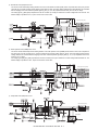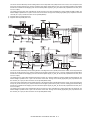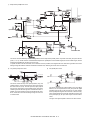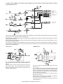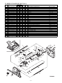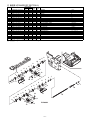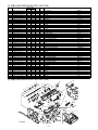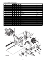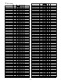
1
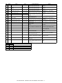
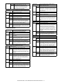
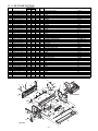
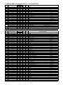
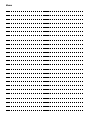
No.
1
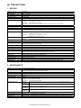
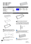
Signal
FULD
Name
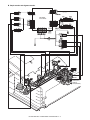
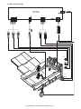
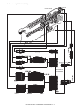
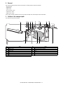
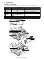
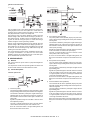
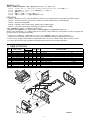
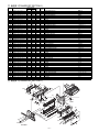
Tray upper limit sensor
Type
Photo interrupter
2
FMLLD
Photo interrupter
3
FLLD
Tray intermediate lower limit
sensor
Tray lower limit sensor
Photo interrupter
4
FBED
Tray paper empty sensor
Photo interrupter
5
6
FSLD1
FSLD2
Paper surface sensor 1
Paper surface sensor 2
Photo interrupter
Photo interrupter
7
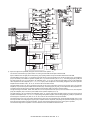
FSTHPD
Stapler HP sensor
Photo interrupter
8
FSTPD
Empty sensor
Photo interrupter
9
FFJHPD
Alignment plate HP sensor F
Photo interrupter
10
FRJHPD
Alignment plate HP sensor R
Photo interrupter
11
FED
Inlet port sensor
Photo interrupter
12
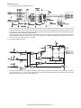
FRLD
Roller up/down sensor
Photo interrupter
13
FBRD
Take-up belt sensor
Photo interrupter
14
FDSW
Front cover switch
Photo interrupter
15
FJPD
Alignment plate position sensor
Photo interrupter
16
FSHPD
Stapler home sensor
17
FSD
Staple empty sensor
18
FSTD
Self priming sensor
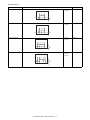
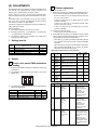
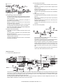
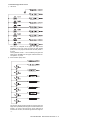
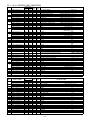
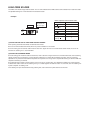
FSLD1
TP5
“L”
“H”
“H”
“L”
FSLD2
TP6
“H”
“H”
“L”
“L”
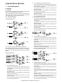
Function/Operation
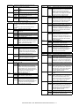
Detects the upper limit position of the
paper load tray up/down shift area.
Detects the intermediate position of the
paper load tray up/down shift area.
Detects the lower limit position of the
paper load tray up/down shift area.
Detects paper empty in the paper load
tray.
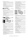
Detects the surface position of paper on
the tray in combination of the both sensors
outputs.
Detects the home position of the stapler
unit in F/R direction shift.
Detects paper empty on the process tray.
Detects the home position of the alignment
guide on F side.
Detects the home position of the alignment
guide on R side.
Detects paper in the inlet port of the
finisher.
Detects the upper standby position of up/
down movement of the bundle exit roller.
Detects up/down positions of the take-up
belt.
Detects open/close of the jam release
cover in the front section.
Detects entry of the process section rear
edge stopper into the opening of the
stapler and inhibits stapling.
Detects the home position of the stapling
mechanism. (Sensor built in the stapler
unit)
Detects staple empty. (Sensor built in the
stapler unit)
Detects the staple feed is completed and it
is ready for stapling. (Sensor built in the
stapler unit)
Output
TP1 is driven to “L” at the upper limit
position.
TP2 is driven to “L” at the intermediate
position.
TP3 is driven to “L” at the lower limit
position.
TP4 is driven to “L” when paper is
provided.
*Refer to the separate table outside the
column.
TP7 is driven to “H” at the home position.
TP8 is driven to “H” when paper is
provided.
TP9 is driven to “L” at the home position.
TP10 is driven to “L” at the home position.
TP11 is driven to “H” when paper is
provided.
TP12 is driven to “L” when the roller
reaches the upper standby position.
TP13 is driven to “L” when the take-up belt
is on the upper side.
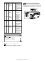
TP15 is driven to “L” when the cover is
closed.
TP50 is driven to “L” when the stopper
enters the opening of the stapler.
TP51 is driven to “H” at the home
(standby) position.
TP53 is driven to “L” when staple empty.
TP52 is driven to “H” when in the ready
state.
State
The paper detection lever is in the save position.
The paper surface is upper than the reference level.
The paper surface is at the reference level.
The paper surface is lower than the reference level.
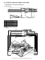
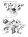
MX-FNX1/MX-PNX1 EXTERNAL VIEW AND INTERNAL STRUCTURE 4 – 2