1
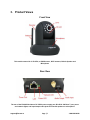
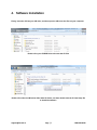
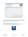
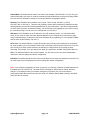
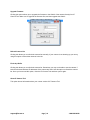
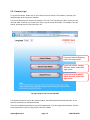
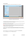
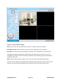
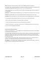
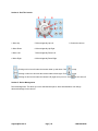
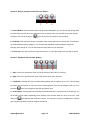
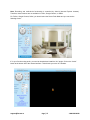
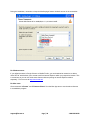
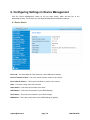
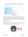
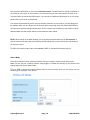
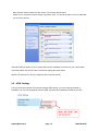
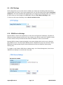
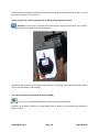
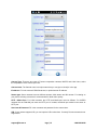
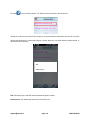
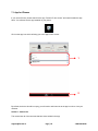
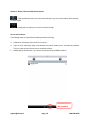
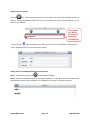
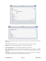
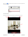
Foscam Digital Technologies LLC
FI8910W User Manual
IP Wired / Wireless Camera
www.foscam.us
[email protected]
Page | 0
1-800-930-0949
Thank You for Your Purchase!
Foscam IP Cameras are designed and equipped primarily for local and
remote purposes such as home or office security surveillance. We provide
a variety of products suitable for any type of surveillance system setup,
including wired/wireless IP outdoor bullet cameras, IP outdoor dome PTZ
cameras, and IP Indoor PT cameras.
Please check the packaging to make sure you have received all items
including the camera accessories as follows:
-
Foscam IP Camera
Wi-Fi Antenna (If Wi-Fi compatible)
Network Cable
Warranty Card
Quick Installation Guides
Power Supply
Installation / Driver CD
Mounting Bracket
Note: Please contact us immediately if there are any damaged items or if
the package is short of any of the accessories listed above.
If you have any additional questions or concerns, please feel free to contact
us at [email protected] or call us at 1-800-930-0949.
[email protected]
Page | 1
1-800-930-0949
Table of Contents
1. Product Introduction .................................................................................................................................. 4
2. Product Specifications............................................................................................................................... 4
3. Product Views ........................................................................................................................................... 5
4. Software Installation .................................................................................................................................. 7
5. Hardware Installation ................................................................................................................................ 9
5.1 - IP Camera Tool ........................................................................................................................... 10
5.2 - Camera Login ............................................................................................................................. 15
5.3 - Device Status .............................................................................................................................. 20
5.4 - Surveillance Window ................................................................................................................... 21
6. Configuring Settings in Device Management ...................................................................................... 2929
6.1 – Device Status ............................................................................................................................. 29
6.2 – Alias Settings ............................................................................................................................. 30
6.3 – Date & Time Settings ............................................................................................................... 300
6.4 – User Settings ............................................................................................................................ 311
6.5 – Multi-Device Settings ............................................................................................................... 322
6.6 – Basic Network Settings ............................................................................................................ 344
6.7 – Wireless Settings ..................................................................................................................... 366
6.8 – ADSL Settings .......................................................................................................................... 411
6.9 – UPnP Settings .......................................................................................................................... 422
6.10 – DDNS Service Settings .......................................................................................................... 422
6.11 – Mail Service Settings.............................................................................................................. 444
6.12 – MSN Settings ......................................................................................................................... 455
6.13 – FTP Service Settings ............................................................................................................. 477
6.14 – Alarm Service Settings ......................................................................................................... 4949
6.15 – PTZ Settings .......................................................................................................................... 511
[email protected]
Page | 2
1-800-930-0949
6.16 – Upgrade Device Firmware ..................................................................................................... 522
6.17 – Backup & Restore Settings .................................................................................................... 533
6.18 – Restore Factory Settings........................................................................................................ 533
6.19 – Reboot Device ........................................................................................................................ 533
6.20 – Log ......................................................................................................................................... 544
7. Phone App .............................................................................................................................................. 55
7.1 – App for Android Phones ............................................................. Error! Bookmark not defined.5
7.2 – App for iPhones .......................................................................... Error! Bookmark not defined.3
8. Video Setup Guides ................................................................................................................................ 69
8.1 – For Windows .............................................................................................................................. 69
7.2 – For Mac ...................................................................................................................................... 69
9. Frequently Asked Questions ................................................................................................................... 70
10. Technical Support ............................................................................................................................... 700
[email protected]
Page | 3
1-800-930-0949
1. Product Introduction
The Foscam FI8910W Wireless Pan/Tilt Indoor IP Camera features high quality video and audio, wireless
N connectivity, pan/tilt, remote internet viewing, motion detection, night vision, embedded IR-Cut filter, as
well as a built in network video recording system. In addition, it is also smartphone compatible (iPhone,
Android & Blackberry) as well as viewable over the internet using standard web-browsers. The camera
functions well as an iPhone baby monitor or as part of a home or office security system with remote
monitoring. It is also compatible with Synology, Blue Iris, and most other surveillance software programs
and NVRs which accept standard MJPEG streams.
2. Product Specifications
- Powerful high-speed video protocol processor
- High definition color CMOS sensor
- 300k Pixels (640 x 480 maximum resolution)
- IR Night vision (Range of 8 meters)
- Panning ability of 300 degrees, Tilt ability of 120 degrees
- Optimized MJPEG video compression for transmission
- Multi-level user management and password definition
- Wi-Fi compliant with wireless standards IEEE 802.11 b/g/n
- Supports an IR-Cut filter for true colored video (no discoloration)
- Supports Dynamic IP (DDNS, No-IP) and UPnP LAN and Internet (ADSL, Cable Modem)
- Features motion detection and alarm triggering, alarm notifications sent via e-mail
- Supports image snapshots
- Supports multiple network protocols: HTTP, TCP/IP, UDP, SMTP, PPPoE, Dynamic DNS,
DNS Client, SNTP, BOOTP, DHCP, FTP
- Supports WEP/WPA/WPA2 wireless encryption
- Supports Daylight Savings Time
- Support G-mail for e-mail notifications
- Supports apps for Android and iPhone (Live Cams Pro, TinyCam Monitor, Foscam IP Cam Viewer)
- Supports one-way audio on Firefox and Chrome, audio supported on Safari via third party apps
[email protected]
Page | 4
1-800-930-0949
3. Product Views
Front View
This model comes with 11 IR LEDs, a CMOS sensor, Wi-Fi antenna, Built-In Speaker and
Microphone
Rear View
The rear of the FI8910W includes a DC 5V/2A power supply port, RJ-45/10-100 Base T port, power
and network lights, and input/output audio jacks for external speakers or microphone.
[email protected]
Page | 5
1-800-930-0949
Bottom View
The bottom of the camera shows the wired/wireless MAC addresses of the camera. It also shows
the S/N number and has a reset button.
If you ever need to reset your camera to default settings, you can use the reset button. Use a pin to push
down the reset button for 10 seconds. Make sure the camera is plugged in and turned on. When the
camera hard resets, it will start to pan and tilt automatically, this signifies that the camera has reset
completely. You should be able to log in with the default username of “admin” with no password in the
password field.
Note: There are three stickers at the bottom of the camera; these stickers are an important feature of
original Foscam cameras. If your camera does not have any of these three stickers, it may be nongenuine. Non-genuine cameras cannot use original firmware and are not eligible for warranty or technical
services. Please make sure you only purchase from an authorized Foscam reseller!
[email protected]
Page | 6
1-800-930-0949
4. Software Installation
Firstly, insert the CD into your CD drive, and then open the CD to see the files on your computer.
Double-click your CD/DVD Drive to browse the CD files
Double-click either the Windows OS or Mac OS folder, and then double-click the IP Cam Setup file
to install the software.
[email protected]
Page | 7
1-800-930-0949
Proceed in installing the IP Camera Tool software on your computer.
Once the installation is finished, the IP Camera Tool software icon installs to your desktop automatically,
look for it on your desktop. If you are using Windows 7 and cannot find the icon on your desktop after
installing the software, please check to see if the path of the camera is correct.
For example, the software may have installed to another folder such as
C:/Windows/System32/IPCamera.exe. If this is the case then fix this by moving or pointing the shortcut to
the correct path, which would be C:/Windows/SysWOW64/IPCamera.exe.
[email protected]
Page | 8
1-800-930-0949
5. Hardware Installation
Note: Before installing and using the Foscam IP camera, please remember to only use the power
adapter that was supplied with the camera. Using other power supplies could potentially damage
your IP camera. Make sure your IP camera is being installed in an indoor environment free from
any type of water or weather effects, such as rain and snow. The camera is built as an indoor
camera and thus cannot stand extremely high or low temperatures.
If you would like to use your IP camera outdoors under a covering such as an eve, make sure
there is no potential of rain or any other type of weather prone to hitting the camera. Also make
sure the temperature is within the camera’s operational temperature range. The camera may
malfunction if the temperature drops below 32 degrees F.
1. Install the Wi-Fi antenna by twisting the antenna connector clockwise to the camera’s antenna port (for
wireless models).
2. Plug the power adapter into the camera’s power supply port. This may be external (outdoor models) or
internal (indoor models) depending on which camera you purchased.
3. Plug the network cable into the RJ-45 connecter which is found either on the external wiring (for
outdoor cameras) or on the back of the camera (for indoor cameras), and plug in the other side of the RJ45 cable to a port on your router/switch.
4. It takes approximately 30 seconds to boot up the camera, you will see the camera swivel automatically
a few seconds after it is plugged in, this indicates the camera has successfully powered on.
5. When the camera is correctly powered on and the network cable is connected properly, the green LED
on either the RJ-45 connector of the camera (for outdoor models) or the connector on the back of the
camera (indoor models) will remain solid. The yellow LED should continue to flash.
Mount the antenna
[email protected]
Plug in the network cable
Page | 9
1-800-930-0949
5.1 – IP Camera Tool
Double click the IP Camera Tool icon and the following screen should appear.
The IP Camera Tool
The IP camera tool should find the camera’s IP address automatically after you plug in the network cable.
If not, please make sure that DHCP is enabled on your router and that MAC address filtering, firewalls
and anti-virus are disabled temporarily until the camera is set up.
MJPEG cameras like the FI8910W will have an “M” next to the local IP address in the software. H.264
compression cameras will have an “H” next to their local IP address.
There are six different options that the IP Camera Tool has. Highlight a camera in the IP Camera Tool list
and right click on it. The six options that appear are: Basic Properties, Network Configuration, Upgrade
Firmware, Refresh Camera List, Flush Arp Buffer, and About IP Camera Tool.
IP Camera Tool showing six different options after right-clicking.
[email protected]
Page | 10
1-800-930-0949
Basic Properties
Clicking this option shows some device information about the IP Camera, such as the Device ID, the
Firmware version, and the Web UI version.
If there are several cameras on the list such as above, you can choose basic properties to check the
device ID and identify the IP address belonging to each IP camera you set up. For example, the device ID
may be 000DC5D203BB. This is the same value seen on the sticker at the bottom of the camera where it
reads “MAC ID.”
Each camera has its own specific MAC ID. Sometimes, if your camera is not found in the IP Camera Tool
software, it may still show up in the router if there is a firewall blocking it. You can add this MAC ID to your
router to give it a fixed IP address. Note that there are two different MAC ID’s. One is for the camera
when it is wired, and the other is for the camera when it is wirelessly connected.
Basic properties in the IP Camera Tool.
Network Configuration
Clicking this option allows you to change the network parameters of your camera, such as the IP address,
Subnet Mask, Gateway, and DNS Server. It also allows you to change the HTTP Port, which is needed
when you want to see the camera remotely by port forwarding in your router.
Obtain IP from DHCP Server: You also have the option to enable this, which allows the camera to have a
dynamic IP address on the local network. This means that if you set up the camera this way, you may
have an IP address of 192.168.1.3 for one day, if you unplug the camera and turn it on again, the IP
address will change. You will most likely not see the camera on the 192.168.1.3 IP address anymore.
Due to this, it is usually, if not always recommended to set a static IP address for the camera.
[email protected]
Page | 11
1-800-930-0949
IP Address: This field allows you to change the IP address that the camera is operating at. The first three
sections of the IP address must match your subnet, or in other words, the first three sections of your
router’s IP address. The fourth section needs to be a number that is not already assigned to another
device. In our example, “192.168.1” is the subnet, while “126” is the fourth section value. You can change
this fourth value usually to anything from 10 – 200 if it is not being used by another device on your
network. The first few numbers (1 – 9) may already be used by your router or devices attached to your
network.
It is important to note that you cannot have the same IP address for two different devices on your
network. You can find out your network’s information by logging into your router or going to the Windows
command prompt as seen below. Click Start > type CMD in the search field > push “Enter” > Then type
“ipconfig” in the command prompt and push “Enter.”
Using “ipconfig” in our command prompt, we see that our own “subnet” is “192.168.1.” Our
computer’s fourth section of the IP address is “111.”
[email protected]
Page | 12
1-800-930-0949
Subnet Mask: The default subnet mask of the LAN in this example is 255.255.255.0. You can find your
subnet mask within your router or using the command prompt method seen on the previous page. Make
sure you enter this information exactly as it is into the Network Configuration window.
Gateway: This IP address is the address of your router. This is usually 192.168.0.1, 10.0.01,
192.168.1.254, or 192.168.1.1. There are many different routers that use different IP addresses as their
default gateway; you may have a default gateway that is none of the above. This value mostly depends
on which router you have. As stated previously, you can find this out by logging into your router or using
the command prompt. You can see in our example that it is 192.168.1.1.
DNS Server: This IP address is the IP address of your ISP network provider. You can find the DNS
server in your router or check the locally attached address of your computer like in the previous page
using command prompt. Usually this is the same IP address as your gateway. For our example the DNS
was the same as the Gateway, 192.168.1.1.
HTTP Port: The default LAN port is usually 80. Another port is usually recommended to be set besides
80, such as 8090, or as in our example, 8918. Keep in mind that every IP camera needs to be on its own
port. Usually if you have multiple cameras, the best way to configure them is by making the ports
ascending. For example, if you are starting from 8000, you would then use 8001, 8002, 8003, 8004, etc.
User: The default username of the camera is admin. You will need to put in the correct administrator
username in order to change the network configuration.
Password: The default password of the camera is left blank; do not enter any characters in this field. You
will need to put the correct password in order to change the network configuration.
Note: If your network configuration is not set up properly, you may see a different message instead of an
IP address in the IP Camera Tool. The most common message is “Subnet doesn’t match, dbclick to
change!” This message means your network settings are not properly set, refer to the network
configuration details above and make sure all 4 fields of IP address, Subnet Mask, Gateway, and DNS
server are filled in correctly.
[email protected]
Page | 13
1-800-930-0949
Upgrade Firmware
Clicking this option allows you to upgrade the firmware or the WebUI of the camera directly from IP
Camera Tool. Make sure to upgrade the firmware first, and then upgrade the WebUI.
Refresh Camera List
Clicking this allows you to refresh the camera list manually. If your camera is not showing up you can try
using this option to refresh the cameras in the list.
Flush Arp Buffer
Clicking this allows you to refresh the camera list. Sometimes you may not be able to see the camera if
both the wired and wireless IP addresses of the camera are fixed. Use this option to refresh the camera
list. Once you have used this option, close the IP Camera Tool and then open it again.
About IP Camera Tool
This option shows information about your current version of IP Camera Tool.
[email protected]
Page | 14
1-800-930-0949
5.2 - Camera Login
To log into the camera, double click on your camera in the IP Camera Tool software, it will open your
default browser to the camera’s IP address.
You can see below that our camera’s IP address is 192.168.1.125, and the port is 8910. If your port was
set to 80, which is default, you will not see a colon or port at the end of the URL. For example, if our port
was 80, we would only see: http://192.168.1.125.
If you use Internet Explorer,
select this login mode
If you use Firefox, Google
Chrome, Safari, select this
login mode
If you are using a mobile
phone browser, select this
login mode
The login page for the Foscam FI8910W
The default username to log into the camera is admin, the default password would be left blank, do not
enter any characters into the password field.
There are two different login buttons. Use the first login button if you are using Internet Explorer. Use the
second login button if you are using Firefox, Chrome, or Safari.
[email protected]
Page | 15
1-800-930-0949
For Internet Explorer
If you choose the first login button, you will be taken immediately to the live video page.
Click “Allow” to be able to see the live video.
The first time you log into the camera, you may receive an ActiveX prompt, such as the one seen above.
You should have the option to click “Allow” or “Run Add-on.”
After doing this, you will need to login to the camera again, make sure to put in the default username and
password and click on the first login button again.
Note: If you still cannot see video even after running or allowing the ActiveX to configure correctly, try
changing your port number to another port other than 80. Also make sure firewalls or antivirus is not
blocking the download or installation of the addon.
You may also see an error that reads “Windows has blocked this software because it can’t verify the
publisher.” This error is related to the DVM_IPCAM2 ActiveX Control Module. To fix this, continue to the
following steps.
Open Internet Explorer if it is not already opened. Click on Tools, then click Internet Options.
Next, click the Security tab, then click the Custom Level button.
[email protected]
Page | 16
1-800-930-0949
In the Custom Level settings, scroll down to the heading “ActiveX controls and plug-ins.”
Ensure the following options are set to “Enable.”
“Run ActiveX and plug-ins,”
“Download Signed ActiveX Controls,”
“Script ActiveX controls marked as safe for scripting.”
Ensure the following options to “Prompt.”
“Download unsigned ActiveX controls,”
“Initialize and script ActiveX controls no marked as safe,”
Click OK and then click Apply. Then click OK on the Internet Options main window. Make sure to restart
the browser for the settings to take effect.
[email protected]
Page | 17
1-800-930-0949
One last setting you will want to check is in the Advanced tab. Click on the Advanced tab on the Internet
Options main window. Scroll down to the Security section. Make sure to check the box that reads “Allow
software to run or install even if the signature is invalid.”
[email protected]
Page | 18
1-800-930-0949
You should now be able to see live video in Internet Explorer! You should see a screen similar to the
below picture:
The live video page in Internet Explorer
For Firefox, Google Chrome, Safari, or any other standard browser:
Click on the second login button on the login page. You will be taken to the device status page of the
camera. It will then prompt you to enter the username and password in a separate window. Enter the
default username of admin and leave the password field blank, then push Enter.
Click on the Live Video button on the left of the page to go to the Live Video page.
[email protected]
Page | 19
1-800-930-0949
The live video page in Chrome, Firefox, or Safari
5.3 - Device Status
If you would like to view the device information, choose “For Administrator” and then click “Device Info”
Device Info shows you the status of different camera settings, and also the firmware and Web UI
versions of the camera.
[email protected]
Page | 20
1-800-930-0949
5.4 The Surveillance Window
Selecting ActiveX mode will take you to Internet Explorer’s surveillance window.
1
6
2
3
4
5
7
Section 1: Device Name
The default device name is Anonymous. You can define a custom name for your camera.(Please go to
Chapter 3.1 for more information).
Section 2: Multi-Device Window
This option can be used to see up to 4 or 9 cameras simultaneously on the same screen. You can set up
multiple cameras inside the administrative panel by going to “For Administrator,” then clicking “MultiDevice Settings”
[email protected]
Page | 21
1-800-930-0949
.
Section 3: Image Parameter Settings
OSD: OSD is used to add a timestamp on your video. Five different colors are available.
Add OSD on record: Select this option if you’d like to add a timestamp to your recordings.
Resolution: You can choose from two different resolutions, 320 x 240 (QVGA) or 640 x 480 (VGA)
The bigger the resolution, the better the image quality is, but the lower the frame rate is. If you are
accessing the camera via internet and want to get smoother video streaming, please select the QVGA
resolution of 320 x 240.
Mode: There are three different modes you can use for the camera, 50HZ, 60HZ, and Outdoor.
The mode you set depends on the frequency of the electricity and the type of model you have (indoor or
outdoor). If the camera is being installed outside, please use the outdoor mode for best results.
[email protected]
Page | 22
1-800-930-0949
FPS: The number of frames per second. There are many different options to choose from.
By default the “Max” setting will be applied. This allows for the maximum frame rate. You can also choose
from lower frame rates such as 20, 15, 10, 5, 4, 3, 2, 1, 1/2, 1/3, 1/4, and 1/5 FPS.
Usually changing the FPS is used when you want to save more bandwidth. Higher FPS rates will take up
more bandwidth.
Brightness: The default setting for brightness is 6. You can adjust this by clicking the plus or minus sign.
Contrast: The default setting is 4, you can adjust the contrast by clicking the plus or minus sign.
Preset/Go: This function allows you to set a custom preset and then call that preset at your convenience.
- Preset: Supports 8 preset positions, which can be set for any point on the camera range.
- Set: Click Set to save the position you need the camera to remember.
- Go: Click Go to make the camera move to the preset position you’ve chosen.
- Numbered Drop-down: You can choose one preset from 1-8 using this drop down list, and click Go to
move the camera towards that preset position.
How do you call preset positions?
Presets can be chosen from 1 – 8. For example, click on the drop down list and choose a preset number.
In this example we’ll choose preset 1.
First, select preset 1 using the drop down list. Then, move the camera to your desired location and stop at
that position. Click the “Set” button to save this position as a preset. After this you can select the next
preset (such as #2) from the drop down list to set your next preset. You can repeat the previous steps for
this preset and so forth.
When you want to call the specific preset, just choose the preset number from the drop down list, and
push “Go”. The camera will automatically pan and tilt towards that specific location.
Flip & Mirror: You can flip the image 180 degrees horizontally by checking the Flip button, or mirror the
image 180 degrees vertically by checking the Mirror button.
[email protected]
Page | 23
1-800-930-0949
Section 4: Pan/Tilt Controls
5
1
6
9
3
4
7
2
8
1: Move Up
5. Move diagonally Up-Left
2. Move Down
6. Move diagonally Up-Right
3. Move Left
7. Move diagonally Down-Left
4. Move Right
8. Move diagonally Down-Right
9. Center the camera
: Clicking on this icon will make the camera rotate up and down. Click
to stop.
: Clicking on this icon will make the camera rotate left and right. Click
to stop.
: Clicking on this icon will make the camera’s IR (night vision) turn on. Click
to turn them off.
Section 5: Device Management
Device Management: This takes you to the administrative panel, where administrators can change
advanced settings for the camera.
[email protected]
Page | 24
1-800-930-0949
Section 6: Record, Snapshot, and Full Screen Buttons
2
1
3
1 - Record Button: Click this button and a pop-up window will appear, you can choose your storage path
for video and put the file name you would like for the recording. Once you push OK the camera will start
recording. The icon will change to
, you can click the icon again to stop recording.
2 - Snapshot: Click this button to take a snapshot of the current video feed on the camera. This will open
up another window with the snapshot. You can save this snapshot by right clicking the image and
choosing “Save image as”. You can then save the image wherever you would like.
3 - Full Screen: Click this to make the camera full screen. You can also double-click the video to do this.
Section 7: Play/Stop/Talk and Audio Buttons
1
2
3
4
1 – Play: Click this to activate the video feed of the camera (if the video is not active).
2 – Stop: Click this to deactivate the video of the camera (if the video is active).
3 - Talk Button: Clicking this icon will enable talking through the microphone on your PC. This will allow
input from your microphone to come out of the camera speakers. The icon will change to this icon once
activated:
Click the icon again to stop the microphone input.
4 - Audio Button: Clicking this icon will enable sound captured by the camera’s built-in microphone. You
will be able to hear what is happening at the location of the camera. When you click on the icon, it will
change to
, this signifies that the audio is active. You may need to plug in headphones or activate
your computer speakers to hear the camera microphone.
[email protected]
Page | 25
1-800-930-0949
Onscreen Mouse Control
Double clicking your right mouse button while hovering over the video feed will enable onscreen mouse
control. This allows you to move the camera using your mouse on the screen. If done correctly, when
moving your mouse over the edges of the video feed, your cursor will change from the mouse pointer to
an arrow, depending on which direction you are hovering over. You can click your left mouse button
when using onscreen mouse control to move the camera to your liking. To cancel this feature, just double
click your right mouse button when hovering over the video feed again.
For example, double click the right mouse button when hovering over the video feed, then left click on
the top part of the screen, you should see the blue arrow appear. The camera should start moving
upwards. If you double click the right mouse button again, this will cancel the onscreen mouse control.
[email protected]
Page | 26
1-800-930-0949
Note: Recording and multi-device functionality is controlled by ActiveX (Internet Explorer browser).
Therefore, these functions are not available in Firefox, Google Chrome, or Safari.
For Firefox, Google Chrome, Safari, you should select the Server Push Mode and you can see the
following screen:
If it’s your first time using audio, you need to download and install the VLC plugin. Click on the “Audio”
button at the bottom left of the camera interface. This will take you to the VLC website.
[email protected]
Page | 27
1-800-930-0949
During the installation, remember to keep the Mozilla plugin feature checked as seen in the screenshot:
For Windows users:
If your default browser is Google Chrome or Mozilla Firefox, you can download an extension or add-on
called “IETab” which allows you to create a tab from Internet Explorer within your respective browser. This
is convenient as you can use all the same features without opening an Internet Explorer window
separately. Find out more at http://www.ietab.net/
For Mac users:
We recommend “uFoscam” and “IP Camera Viewer” from the Mac App store to use the above features
in a standalone program.
[email protected]
Page | 28
1-800-930-0949
6. Configuring Settings in Device Management
Click the “Device Management” button on the live video screen, which will take you to the
administrative panel. This is where you can adjust administrative and advanced settings.
6.1 Device Status
Device ID – This is the MAC ID of the camera by a wired Ethernet connection.
Device Firmware Version – This is the current firmware version of the camera.
Device Web UI Version – This is the current Web UI version of the camera.
Alias – This is the current name of the camera.
Alarm Status – This is the current status of the alarm.
DDNS Status – This is the current status of your DDNS Settings.
UPnP Status – This is the current status of your UPnP Settings.
MSN Status – This is the current status of your MSN Settings (if applied)
[email protected]
Page | 29
1-800-930-0949
6.2 – Alias Settings
The default alias is anonymous. You can change the name of your camera to anything you would like with
a few exceptions. You cannot use some special characters like “/, :/ *, ?, “, <, >, or |.” If you use these
characters the camera will not be able to create a recording file.
Usually it is a good idea to name each camera based on the location you are setting the camera in,
especially if you have multiple cameras. Click Submit to save changes. Some examples are Kitchen
Cam, Baby Cam, etc.
6.3 – Date & Time Settings
Here you can choose the time zone of your country. You can choose Sync with NTP Server or Sync
with PC Time. Usually syncing with the PC time is the best option to choose. If your country is
implementing Daylight Savings Time, such as in the US, you can set it for your camera here.
[email protected]
Page | 30
1-800-930-0949
6.4 – User Settings
Here you can set permissions for visitors, operators, and administrators. Visitors have access to view the
camera, record, take snapshots, use audio, and enable an onscreen display. Operators are able to do
everything visitors can do, with the added abilities to pan and tilt the camera, change brightness and
contrast settings, change FPS settings, and flip/mirror the camera. Administrators are able to do all of the
previous features with the added ability to go into device management and adjust all of the settings of the
camera.
On the User Settings page you can set the location you would like alarm video recordings to save. You
can set the path for alarm recordings as well if you would like to a separate path, using the “Set
AlarmRecord Path” option. Click “Browse” to choose the folder you would like to save recordings to.
Note that you need to keep each camera open in a separate browser window to save alarm recordings.
If you receive an error such as “Set the record path fail” when you try to select a path to save
recordings, try configuring the following:
Navigate to Tools, then Internet Options. Click on the Privacy tab at the top, then click “Sites.” You will
need to add the camera as a trusted site. Insert the URL (IP address of the camera) in the trusted sites
field and click “Allow” to add it. Push OK and Apply, then restart your browser.
If you still have problems, navigate to Internet Options again, then under the “Security” tab, try
unchecking the box which reads “Enable Protected Mode.” Click Apply, then OK, then try restarting the
browser, logging into the camera, and setting the path again.
[email protected]
Page | 31
1-800-930-0949
6.5 – Multi-Device Settings
The embedded camera software is able to support a maximum of 9 cameras simultaneously on the same
screen. As long as the camera is of MJPEG compression, you will be able to add it as an additional
camera and view its video using the multi-camera panes on the Live Video page.
On the Multi-Device Settings page you will be able to see all the cameras currently present on your LAN
(Local Area Network), meaning any cameras connected directly to the same router will be seen in this list.
st
The 1 Device on this page is referring to the camera you are currently logged into. If you would like to
nd
add a second camera, click the 2 Device and a list will expand, showing the Alias, Host, HTTP Port,
and User/Password fields. If you want to add a camera from your LAN, click on a camera from the list,
and it will automatically populate the Alias, Host, and HTTP Port fields. You will need to add the
Username and Password individually. You can add up to 9 cameras this way.
Click a camera in the list. The
alias, host and HTTP Port will
be filled in the following boxes
automatically
Enter the User name and
password of the 2nd camera
Click Add to save the
camera, then push Submit
to save all settings.
[email protected]
Page | 32
1-800-930-0949
Once you finish adding a camera, click “Add.” You can then proceed to add additional cameras until you
are finished. Once you have added all cameras, click the “Submit” button to save settings.
Note that you will only be able to see the added cameras on your local network, if you try to access your
cameras remotely, you will not be able to see them unless you change the Local IP addresses to External
IP addresses (this is explained further in the Quick Installation Guide). If you would like to see the
cameras remotely, instead of putting the LAN IP address of the camera, you will need to change this to
your External IP address (which can be found at www.whatismyipaddress.com) or your DNS hostname if
you are using a DNS service (make sure to exclude http:// from the hostname).
An example of 4 cameras set up using Multi-Device Settings
[email protected]
Page | 33
1-800-930-0949
6.6 – Basic Network Settings
If you would like to set a static IP for the camera (highly recommended), you can do so on the Basic
Network Settings page. Keep the camera in the same subnet of your router or computer. Our subnet in
this example is “192.168.1.”
You will notice that most of these settings are exactly the same as the settings seen in the IP Camera
Tool software. You can use this method of changing the network information as an alternative to using IP
Camera Tool if you would like.
If you are unsure of your subnet mask, gateway, or DNS server, you can always check by using the
methods explained in Section 5.1 of this manual.
An alternative way to find your network information (Windows 7) is by clicking Start, then clicking Control
Panel. Once Control Panel opens up, click on “View Network Status and Tasks” or “Network Sharing
Center.” This will take you to the network status screen. Where it reads “Connections,” click your
connection to open the “Local Area Connection Status” page. Then click “Details.”
Once the details screen pops up, you will see similar network information; use this information to fill or
double-check the fields you have.
[email protected]
Page | 34
1-800-930-0949
Use the Network Connection Details window to double check your network settings.
Make sure you are looking at the fields that start with “IPv4.” You will see Subnet Mask, Default Gateway,
and DNS Server as seen in the screenshot above. Check your subnet as well, for example, our subnet in
the screenshot above is “192.168.1.”
Note that the IP address seen in the network connection details is actually the IP address of our
computer. Make sure the fourth section of your camera’s IP address does not match this IP address.
Every device on your network must have its own separate IP address. As such, the camera cannot have
the same IP address as your computer. Keeping this in mind, also remember that if you are setting up
multiple cameras, they cannot have the same IP address or port number. Be sure to change both the
address and the port if they are being shared by another camera.
[email protected]
Page | 35
1-800-930-0949
6.7 – Wireless Settings
If you would like to setup the camera wirelessly, you can follow the steps below. Using a wireless
connection for the camera allows you to move the camera anywhere in the location as long as the
camera has a stable connection with your router. All you will need to do is plug it in with a power supply
and the camera will connect wirelessly.
1)
When you are logged into the camera, click on the setting that reads “For Administrator.” You
should be logged in as an administrator already with the default username and password.
2)
Next, click on the setting on the left side that reads “Wireless Settings.”
3)
On this screen you will see the wireless settings page. You can use the “Scan” button to scan
for local wireless networks. If you choose this method, you can click on your wireless network
and the fields will automatically populate except for the “Share Key” field. Enter your wireless
network’s password in this field.
4)
Sometimes you may need to enter the wireless information manually. Check the box that states
“Using Wireless LAN” for further options to drop down. You will see a few different fields. You
should find and note down the following information about your wireless network:
a) SSID – The name of your wireless network (Our example will be Foscam H264)
b) Encryption method (e.g., WPA/WPA2/WEP)
c) Encryption technique (e.g., TKIP/AES/TKIP-AES)
d) Share key – This is the password you use to connect to your wireless network
[email protected]
Page | 36
1-800-930-0949
To find the above information you may need to log in to your wireless router. To do this, enter the IP
address of your router into your browser and press enter. You will be prompted to enter your router
username and password. If you do not know the IP address of your router you can view it in IP Camera
Tool by selecting and right clicking on your camera, selecting “Network Configuration”, and noting down
the “Default Gateway” IP address. This Default Gateway IP address is the IP address of your router.
Once logged in to your router look for an option called “Wireless Settings” or “Wireless LAN”. Once in the
Wireless Settings look for and jot down what you have for the setting called “SSID”.
Next, look under the “Security Settings” under “Wireless Settings’ and write down the “Encryption
Method”, “Encryption Technique” and the “Shared Key”.
[email protected]
Page | 37
1-800-930-0949
If you are running Windows 7 and are connected to the same wireless network you are trying to set up,
you can also find this information out by clicking on the Wireless icon in your task bar to bring up all
wireless networks, right clicking your network, and clicking “Properties.”
When you click on “Properties,” the network properties window will come up with the same information
you need to enter under the “Security” tab, our example is below:
[email protected]
Page | 38
1-800-930-0949
5)
Once you have the information about your network, on the wireless settings page, enter the
information about your wireless network into the fields. You can see our example below:
Make sure your camera has the wireless antenna plugged in. Push Submit to save the settings. The
camera will start to countdown as it needs to reboot. Once it has come to a stop, you can unplug the
Ethernet cable and you should start to see the green LED on the back of the camera flashing much faster
after about 30 seconds. Open IP Camera Tool again and the camera should appear. It may be operating
under a different IP address than what you had set before. Make sure to set a static IP address for the
camera again just in case.
WPS (Wi-Fi Protected Set-up)
WPS allows you to set up wireless connectivity automatically if you have a WPS-compatible router. The
WPS button on the Foscam camera is shared with the reset button. Use the small end of a paperclip or a
toothpick to press and hold the RESET button for four seconds and let go.
Reset
Button
[email protected]
Page | 39
1-800-930-0949
Next, press the WPS button on your router within 60 seconds. The WPS button is usually on the back or
on the side of your router. On some routers, you may need to log in to the web interface and click on an
on-screen button to activate the WPS feature. If you are not sure where the WPS button is on your router,
please refer to your router’s User Manual.
The camera will automatically create a secure wireless connection to your router. If you have plugged in
the network cable, you can disconnect it at this time. While connecting, the green network light will blink
quickly and the wireless settings will take effect. The IP Camera Tool will search for the camera’s LAN IP
address. Make sure that the PC and the camera share the same subnet.
NOTE: When setting up the WPS Settings, you must press the Reset button only for four seconds, or
else the camera may reset itself back to factory default settings if you press and hold the reset button for
10 seconds or more.
For WPS, the security mode of the router cannot be WEP, or else the WPS settings may fail.
Adhoc Mode
Using this mode, the Foscam camera will directly connect to a host in a peer-to-peer environment.
Make sure the PC has a wireless network card plugged in. Enable the wireless on the wireless LAN
settings page and choose Adhoc mode.
Fill in an SSID to identify the Foscam camera and then set the security mode, you can choose none or
another type of encryption. Click Submit.
[email protected]
Page | 40
1-800-930-0949
Next, take the network cable out of the camera. The camera should restart.
Search for the camera’s wireless network around the area. You should be able to find the SSID that
you set for the camera.
Select the SSID you filled in for your camera and enter the password you filled in for your camera when
connecting. Make sure the PC and the camera are sharing the same subnet.
Open the IP Camera Tool, and you should be able to find the camera.
6.8 – ADSL Settings
You can connect the camera to the internet through ADSL directly. If you are using this method of
installation, you can use this page to enter the ADSL username and password provided by your ISP.
[email protected]
Page | 41
1-800-930-0949
6.9 – UPnP Settings
UPnP settings allow you to use the camera’s software to configure port forwarding rather than doing it
manually within your router. If your router supports UPnP, you can check the box that reads “Using UPnP
to Map Port.” The camera software will automatically try to configure port forwarding within your router for
the port number you have assigned as “HTTP Port” under the “Basic Network Settings” page.
To learn more about port forwarding, see the Quick Installation Guide.
6.10 – DDNS Service Settings
Dynamic DNS is a service used specifically for users who have Dynamic IP addresses. A Dynamic IP
address constantly changes several times a day, making it very difficult to track the IP address needed
to view a camera, since you would need the external IP address to connect to the camera.
Dynamic DNS is a feature already embedded in the camera software which can be set to a few third
party DDNS services. The most popular DDNS provider is DynDNS.com (Dyn.com) and No-IP. Other
DDNS services that are third party are also provided and set up for use within the camera (Oray,
3322.org, etc.).
To navigate to the Dynamic DNS Service Settings page, click “Device Management,” then click on
“DDNS Service Settings” on the left side of the page.
[email protected]
Page | 42
1-800-930-0949
This page allows you to choose a third party DDNS service, please disable the manufacturer’s DDNS first,
and then input your third party DDNS information. This requires you to enter the username and password
for the service you are using, along with your hostname.
For example, in the following screenshot we are using the information from our No-IP DNS account:
To receive a free DNS hostname, try using the DynDNS Trial Account at http://dyn.com/dns/dyndns-profree-trial/ or the No-IP free hostname at http://www.no-ip.com/newUser.php.
When you create your account, remember to write down your username, password, and the host that you
have set up for your account.
Our host in this case was foscamusa1.no-ip.org. An example of a DynDNS host would be
foscamusa1.dyndns.org.
Once the DDNS settings are configured properly, head to the Device Status page to see if the DDNS
status is correctly set up.
[email protected]
Page | 43
1-800-930-0949
Above you can see that under the “DDNS Status” field, we see “No-IP Succeed” with the hostname
afterwards. This indicates that DDNS was set up properly. You can now access the camera using the
hostname URL listed. In our case, this is http://foscamusa1.no-ip.org:8910
Note that you will always need to add the port number with a colon after the initial hostname to point to
your specific camera.
6.11 – Mail Service Settings
If you would like to receive e-mail notifications when motion is detected, you can set up Mail Service
Settings and configure it to your e-mail address.
[email protected]
Page | 44
1-800-930-0949
To get started, make sure that the e-mail provider you are using supports SMTP. As seen above, you can
send e-mails to up to 4 e-mail addresses. The SMTP port is usually set at 25 if there is no Transport
Layer Security. Some SMTP servers have their own ports, such as 587 or 465. If using G-mail, set the
Transport Layer Security to either TLS (use port 465) or STARTTLS (use port 25 or 587). The port you
use will depend on the type of Transport Layer Security chosen. You can see an example of the G-mail
settings we use above.
Report Internet IP by Mail is a very useful tool to keep enabled; this feature will send you an e-mail
when your external IP address changes. Usually if you have a dynamic IP address, this feature will let
you know when the IP address has changed so you can connect to the camera
Keep in mind that if you are only sending e-mails to one e-mail address, you can use the same e-mail for
the sender and receiver, as seen above. Also to ensure you are receiving e-mails when there is motion
detection, make sure “Send Mail on Alarm” is checked in the Alarm Service Settings page.
Note: When setting up e-mail settings, push Submit first, and then push Test if you would like to test the
e-mail settings. Test will not work unless the settings are submitted to the camera first.
6.12 – MSN Settings
This feature allows you to chat to your camera to find out the current IP address it is running at. To do
this, enter the MSN Settings page in the camera as seen below:
[email protected]
Page | 45
1-800-930-0949
The first two fields are the username and password you will give to the camera. The camera will be
logged on at all times to this specific username on MSN Messenger. Because of this, it is recommended
to create a new username specifically for the camera.
The MSN Friends List allows contact between the camera and yourself or any other accounts. Input as
many MSN contacts here as needed. Any contacts listed here will be able to chat to the camera and ask
for the camera’s URL, so take note of this.
Once the username, password, and contacts are listed, push Submit.
Next, you can open MSN Messenger on your computer, and log into your account. In this example, we
would be logging into “[email protected].”
Once logged in, the username the camera is logged in with will appear in the friends or contacts list. In
our example, it would be the username associated with “[email protected].” You can then open a
chat with the camera’s username, and type “url?”
Once you send this chat, the camera will send back the URL of the camera to you.
You can see in the above screenshot that the camera (with the username “Raheel N” has sent back the
URL of the camera after we asked for the URL, by typing “url?” and sending the chat.)
[email protected]
Page | 46
1-800-930-0949
The benefit of this is if you somehow lose the IP address of the camera and you are not near the camera
location, you can always sign in to MSN Messenger and retrieve the IP address this way.
Also note that if you have e-mail notifications enabled, you can check the box that states “Report Internet
IP Address by Mail,” which will allow the IP address to be e-mailed to you every time the camera boots up
or changes IP addresses.
6.13 – FTP Service Settings
This feature allows for FTP services to work with the Foscam camera. Using the FTP feature allows
images to be uploaded to an FTP whenever motion is detected.
You can enter your FTP server details in the above settings page, enter your FTP server, port, and
upload folder. We recommend using your own FTP or a third party FTP service like www.cameraftp.com
which we are using in the above screenshot.
For the FTP Upload Folder, make sure you create this folder yourself, as the camera is not able to create
folders on the FTP. Also make sure the folder can be erased.
FTP Modes supported are PASV and POST modes, check with your FTP to see which mode it uses.
The feature named Upload Image Now will upload images when this box is checked. If the box is not
checked you will not receive any uploads.
[email protected]
Page | 47
1-800-930-0949
Enable Set Filename allows you to set a name for the uploaded image files, if you select this, the
uploaded images will be named after the specific filename you set in the box below this.
Filename allows you to fill in the name of the uploaded image to a specific name you would like to
choose. This name is different from the alarm images that are uploaded; the alarm image names cannot
be changed.
The Upload Interval refers to the time between the current image and the next image that will be
uploaded.
Click Submit to save settings. Once you submit it you can click Test, which will show if the test succeeds.
You may receive the following errors if the FTP information is not correct:
Cannot connect to the server – Make sure the FTP server is correct
Network Error – There may be a connection issue, try connecting again or try a little later.
Server Error – This would also be an issue with FTP server connectivity, double check to see if all the
FTP information is entered properly.
Incorrect user or password – Make sure you are entering the correct credentials to log in.
Cannot access the folder – Verify that the folder you specified is created correctly within the FTP.
Error in PASV Mode – Check to see if your FTP server supports PASV.
Error in PORT Mode – PASV mode should be selected if the camera is behind a NAT.
Cannot upload files – Verify that your account is authorized on the FTP server.
Also be sure to check your FTP parameters. The format of the image filename will usually be something
similar to “00606E8C1930(user)_0_20100728114350_25.jpg”
Make sure your FTP can support this type of file name.
[email protected]
Page | 48
1-800-930-0949
6.14 – Alarm Service Settings
Alarm service settings allow you to enable motion detection. You can set motion detection on a certain
schedule, and set up e-mail notification alerts here as well.
The settings above are explained in detail below:
Motion Detect Armed – This feature enables motion detection. If this is unchecked, motion detection is
disabled and you will not receive any alerts.
Motion Detect Sensitivity – This feature adjusts the sensitivity of the motion detection. The lower the
number, the less sensitive the motion detection will be. If the number is higher, the motion detection will
be very sensitive.
Motion Compensation – This feature will help reduce any false alarms caused by quick light fluctuations
or similar incidents.
Sound Detect Armed – This feature enables sound detection. If this is unchecked, sound detection is
disabled and you will not receive any sound alarm alerts.
Sound Detect Sensitivity – This feature adjusts the sensitivity of the sound detection. The lower the
number, the less sensitive the sound detection will be. If the number is higher, the sound detection will be
very sensitive.
[email protected]
Page | 49
1-800-930-0949
Send Mail on Alarm – If you would like to set up e-mail notifications, check this feature to have e-mails
sent every time motion is detected. If this feature is not checked, you will not receive any e-mail alerts.
Make sure your information on the Mail Service Settings page is filled in correctly.
Upload Image on Alarm – This setting allows you to upload images using the FTP settings you have set
in FTP Service Settings. You can set the upload interval here as well in seconds.
Upload interval – The interval time between two uploaded pictures.
Beep on Alarm – If you select this checkbox, you can hear a beeping alarm when motion or sound is
detected on the browser.
Record on Alarm – If you select this checkbox, the camera will record automatically when motion or
sound is detected to the path specified in the User Settings.
Alarm Record Filepop – This icon controls the pop-up folder feature. When a recording is complete, the
software automatically opens up the folder that the recording was stored in. Uncheck this to stop the
folder from popping up every time there is a new recording.
Scheduler – The scheduler allows you to set certain time periods when you would like motion to be
detected. You can use the scheduler to set times for all 7 days of the week, 24 hours a day. Each
rectangular block in the schedule represents 15 minutes. You can use this system to specify when you
would like to enable motion detection and keep it disabled.
You have the option of not checking scheduler. If you uncheck scheduler, motion detection will be
activated at all times, as long as motion detection is armed.
Clicking the number (that corresponds to the hour) at the top of each column will set motion detection for
that specific hour during the entire week. You can also clear the zones by clicking the number below the
top number.
For example, in the screenshot above you can see that during the entire week, at 3:00 AM – 4:00 AM,
and from 5:00 AM – 6:00 AM, motion detection will be activated. At all other hours during the week,
motion detection will be deactivated.
You can click “Set All” at the top of the scheduler to set motion detection to all the zones easily. You can
also use the button “Clear All” to clear the entire board of any activated zones.
Be sure to click “Submit” when you are finished setting all motion detection settings.
[email protected]
Page | 50
1-800-930-0949
6.15 – PTZ Settings
This page allows for changing any speeds of the camera’s pan/tilt abilities or default positioning of the
camera.
Disable Preset – This option will allow you to disable presets on the camera. If you would like to use
presets, uncheck this box. If unchecked, the second feature “Go Center on Boot” will change to “Go to
preset on boot.” What this feature does is allows you to choose whether you would like the camera to
point a certain way when it reboots or is powered on again.
To have the camera point to a preset, make sure disable presets is unchecked. Set a preset to preset #1
on the live video page. Once you have set the preset, come back to the PTZ Settings page and check
“Go to preset on boot.” Remember, this option will only be available if “disable preset” is unchecked.
Go Center on Boot – This option makes the camera pan and tilt automatically once it is rebooted or
restarted. Uncheck this box if you would like the camera to remain stationary when it is rebooting.
PT Speed – This option allows you to control how fast or slow the pan and tilt speed is of the camera. A
lower value here makes the camera faster. A higher value makes the camera move slower.
Patrol speeds – For patrol speeds, the same concept applies. A lower value here will make the patrol
speed faster, while a higher value will make the patrol speed slower.
Patrol rounds – These settings allow you to control how many rounds the camera will pan or tilt on a
horizontal or vertical cruise. If this value is set to 1, the camera will tilt or pan from the current position
once to the right/top, then it will tilt or pan left/down, and then come back to the center.
Remember to push Submit to save these settings; the camera may have to reboot depending on which
settings are changed.
[email protected]
Page | 51
1-800-930-0949
6.16 – Upgrade Device Firmware
This page allows for updating the camera’s firmware or WebUI. If you need to upgrade or reflash your
firmware or WebUI, you can do so using this page. If you aren’t able to upgrade firmware or WebUI
through the camera this way, you can always use the IP Camera Tool to do this as well.
You can download the latest firmware for your camera from www.foscam.us/firmware. You can also send
us an e-mail at [email protected] or [email protected] if you aren’t able to identify your firmware
version or if you aren’t able to locate an updated firmware.
In the above example, we are updating the firmware to 11.37.2.49 for our camera. Push “Submit” to start
the upgrade process, which may take a few minutes. The camera will reboot and restart with the newer
firmware installed.
Keep in mind that you can only update the WebUI after updating the firmware. Upgrade the
firmware first, then upgrade the WebUI afterwards.
Note: Before you upgrade, be aware of updating the correct version of firmware with Foscam cameras.
There are usually two different firmware versions for each Foscam camera. This is based on actual
camera hardware and not software. The difference is that, if loading a newer camera firmware into your
camera with older firmware, you have to be sure that the first four numbers are exactly the same before
you upgrade. If they are not, you will most likely experience some issues (losing wireless capability) as
certain firmware versions are made for certain camera hardware.
For example if your current firmware starts with 11.22, you must make sure that the firmware you are
upgrading to also starts in 11.22, the way you can see which firmware is newest is by looking at the last
two digits, that should be greater than your current firmware.
For the example above, we were upgrading from our old firmware, 11.37.2.48, to 11.37.2.49. This is the
correct firmware version to update in this example.
[email protected]
Page | 52
1-800-930-0949
6.17 – Backup & Restore Settings
This page allows you save your current settings in case you are going to hard reset the camera and lose
your current settings to factory settings. If you back up your settings this way, you can hard reset the
camera, come back to this page, and restore the settings so that you will have the camera back just as it
was.
If you click the “Submit” button next to “Backup.” The camera will create a backup file that your computer
will automatically download, called “params.bin.”
This is the backup file. If you would like to restore the camera back to these parameters, click “Choose
File” next to the Restore field, and browse to the location of the file. Choose it, and then click “Submit.”
The camera will submit the parameter information and will restore your settings from the file.
6.18 – Restore Factory Settings
Clicking on “Restore Factory Settings” in the administrative panel will prompt you if you would like to reset
the camera back to default factory settings. This is similar to hard resetting the camera where the camera
will lose all of its current information. Click “OK” to restore the camera back to default factory settings.
6.19 – Reboot Device
Clicking on “Reboot Device” in the administrative panel will prompt you if you would like to reboot the
camera. Once you click this, you will be prompted to confirm rebooting the camera. Click “OK” to reboot
the camera, which will take a minute or so. The camera should come back online after this period of time.
[email protected]
Page | 53
1-800-930-0949
6.20 – Log
Clicking the “Log” button in the administrative panel takes you to the log page, which shows information
such as users who are logging into the camera’s live video screen.
The log can only be cleared by rebooting the camera. You can click the “Refresh” button to refresh the log
in case there is any new information available.
[email protected]
Page | 54
1-800-930-0949
7. Phone App
With the Foscam phone app, you are able to view your camera directly just as you would from a computer
at any time, from anywhere, as long as you have an internet connection (usually through 3G or 4G). This
section shows how to set up an iPhone, and Android phone to view Foscam cameras with the phone app.
7.1 App for Android Phones
There are two ways to install the phone App:
First method:
Search for the app, “Foscam IP cam viewer” in the Google Play Store on your smartphone.
Download and install the app, then you should be able to see the app icon within the apps on your phone.
[email protected]
Page | 55
1-800-930-0949
Second Method:
Enter http://play.google.com in the URL field of your phone’s browser, then search for the same app,
“Foscam IP cam viewer”. Once found, download and install the app.
Once the app is fully installed, launch the app on your phone.
Default user
name is admin
with a blank
password
Enter the user name and password, the default username is admin, and the password is left blank by
default.
Click the “Login” button, which will allow you to see the following surveillance windows below.
[email protected]
Page | 56
1-800-930-0949
1
2
3
The default surveillance window is black, you need to add devices to it and then connect the device.
The login window pictured above is divided into three sections, below these sections are detailed:
Section 1: Exit / Go to Device List Buttons
Click this icon to exit the phone app entirely.
Click this icon to go back to the Device List page, where you can edit and add cameras.
Section 2: Live View
If the camera supports pan and tilt functions, you can slide your finger to the direction you would like to go
and the camera will pan and tilt towards that direction.
Section 3: Playback/Snapshot/Audio/Talk Buttons
Playback – Click this button to see the snapshots you have taken with the camera.
Snapshot – Click this button to take a snapshot of the video feed, which is also saved..
Audio button - Click this button to hear sound captured by the camera’s built-in microphone.
Make sure the camera supports audio functionality. Click the icon again to stop audio.
[email protected]
Page | 57
1-800-930-0949
Talk button – Push this button to talk through your phone’s microphone which will come out
from the camera speakers. Your audio will be heard at the camera’s location. Be sure that the camera
supports audio functionality. You can click the icon again to stop the audio.
How to add cameras to the phone app:
The following steps are required before adding cameras to the app:
1) Install the IP Camera(s) which you’d like to monitor.
2) Login to the IP Camera(s) using a web browser using the IP address, port, username & password .
This is to make sure the camera can be accessed remotely.
3)
DDNS settings will also work if you want to add devices using a DDNS hostname.
Click the
button to go to the Device List page. The following section will show you how to add your
cameras to the app.
1
2
3
[email protected]
Page | 58
1-800-930-0949
Section 1: Back button
- Click this icon to go back to the surveillance window.
Section 2: Device List
The device list lists all cameras that are added in the app.
Section 3: Add Device Buttons
These buttons allow you to search and add cameras to the device list.
- Click this icon to search all cameras on your LAN automatically (you must be connected to a
wireless network to scan on that network.) See the following screen for details:
[email protected]
Page | 59
1-800-930-0949
Once the search has finished, select the IP camera you would like to add, and click OK to add it. You will
then see the camera in your device list.
Adding a camera by scanning the QR code or UID (User Identification) number.
- UID Scan: Click this icon to scan the UID number which is located on the bottom of the camera.
The camera will then be added to the app automatically.
Currently Foscam cameras do not support UID’s, however in the future, when UID functionality is added
you can use this feature to add cameras.
Add a device with an external/public IP address (WAN)
- Click this icon to add cameras with public/external IP addresses manually.
Once the icon is clicked, it will take you to the following screen, where you can manually enter information
for your camera.
[email protected]
Page | 60
1-800-930-0949
Camera Type: There are two types of Foscam compression cameras, MJPEG and H.264. Here, select
the compression of the camera you have.
Camera name: The Camera name is a unique name that you can give to identify it in the app.
IP address: Fill in the camera’s DDNS hostname, or public/external IP address.
Stream type: Some cameras have two different streams, Main stream and Sub stream. For viewing on
your phone, selecting sub stream is recommended for faster video quality.
HTTP / Media Port: For H.264 cameras, the HTTP and Media port must be different. For MJPEG
cameras like the FI8910W just enter the HTTP port. If needed, the Media port would be the same as
HTTP port.
Username & Password: Fill in the username and password for the camera here.
UID: If your camera supports UID, you can input the UID number here. Currently Foscam cameras do not
support UID.
[email protected]
Page | 61
1-800-930-0949
Click the
icon to add the camera. You will then see this camera in the Device List.
.
Clicking on a camera in the device list will take you to the surveillance video where you can see live video.
Clicking and holding on a camera will bring up a screen where you can either edit the camera details, or
delete it from the device list.
Edit: This allows you to edit the camera information again if needed.
Delete device: This deletes the camera from the Device List.
[email protected]
Page | 62
1-800-930-0949
7.1 App for iPhones
If you use an iPhone, please search for the app “Foscam IP cam viewer” and install it within the App
Store. You will then see the app installed on your phone.
Click on the app icon which will bring you to the app’s home screen:
1
2
By default, the device list will be empty; you will need to add cameras to the app in order to view your
cameras.
Section 1: Camera list
This section lists all of the cameras that have been added in the app.
[email protected]
Page | 63
1-800-930-0949
Section 2: IPCam Table and Add IPCam buttons
- Clicking this button takes you to the device list where you can see the table of all IP cameras
you have added.
- Clicking this icon allows you to add a camera to the app.
How to add cameras:
The following steps are required before adding cameras to the app:
3) Install the IP Camera(s) which you’d like to monitor.
4) Login to the IP Camera(s) using a web browser using the IP address, port, username & password.
This is to make sure the camera can be accessed remotely.
3)
DDNS settings will also work if you want to add devices using a DDNS hostname.
Click this icon to
add a camera
[email protected]
Page | 64
1-800-930-0949
Adding a device on LAN
Click the
icon and the app will search for cameras within your LAN, these cameras will then be
added to the app automatically. Make sure you are connected to the same wireless network on your
phone as you cameras.
The cameras
on LAN can
be searched
and added
automatically
There is an icon
after the camera name. When you click this you will be asked to enter the user
name, password and HTTP port to log into the camera.
Adding a device on WAN (Public/External IP Address)
Step 1: Click the Add Camera icon
to add cameras manually.
Step 2: Select the compression type for your camera: MJPEG or H.264. Next, enter the camera’s basic
information like camera name, IP address, HTTP/Media Port, Username, Password, and so on.
[email protected]
Page | 65
1-800-930-0949
UID: If your camera supports UID, you can input the UID number here. Currently Foscam cameras do not
support UID.
Device name: The Camera name is a unique name that you can give to identify it in the app.
IP address: Fill in the camera’s DDNS hostname, or public/external IP address.
Username & Password: Fill in the username and password for the camera here.
HTTP / Media Port: For H.264 cameras, the HTTP and Media port must be different. For MJPEG
cameras like the FI8910W just enter the HTTP port. If needed, the Media port would be the same as
HTTP port.
Stream type: Some cameras have two different streams, Main stream and Sub stream. For viewing on
your phone, selecting sub stream is recommended for faster video quality.
[email protected]
Page | 66
1-800-930-0949
Step 3: Click the
button to add the camera to your device list. You can then see the camera name
on the “IP Cam Table” page.
The Surveillance Window
Click a camera on the device list and you will be taken to the surveillance window for live video.
1
2
3
4
[email protected]
Page | 67
1-800-930-0949
For this example, the surveillance window is divided into four sections on the previous page.
Section 1: Back Button
- Click this icon to go back to the IPCam Table/Device List page.
Section 2: Photo Button
- Click this icon to see the snapshots that have been taken on the app.
Section 3: Live View Window
If the camera supports pan and tilt functions, you can slide on the screen with your finger and the camera
will pan and tilt accordingly.
Section 4: Snapshot/Audio/Talk buttons
Talk
Audio
Snapshot
Snapshot - Click this button to take a snapshot of the current video feed.
Audio button - Click this button and you will hear sound captured from the camera’s built-in
microphone. Make sure the camera supports Audio. Click the icon again to stop the audio.
Talk button - Click this button, then talk through your cell phone’s microphone, which will transmit
through the camera’s speakers. People will hear your audio through the camera’s built-in speaker at the
camera location. Make sure the camera supports audio.
Click the icon again to stop audio.
[email protected]
Page | 68
1-800-930-0949
8. Video Setup Guides
8.1 – For Windows
We currently have video guides on our website for Windows users, you can use these setup guides for
setting up the camera from scratch on Windows. These guides were recorded using Windows 7.
You can access our guides by following the link: www.foscam.us/mjpeg-setup-videos
You can also access these videos by using the QR code listed here:
8.2 – For Mac
We currently have video guides on our website for Mac users as well, you can use these setup guides for
setting up the camera from scratch on Windows. These guides were recorded using Mac OSX Lion.
You can access our guides by following the link: www.foscam.us/mjpeg-setup-videos-mac
You can also access these videos by using the QR code listed here:
[email protected]
Page | 69
1-800-930-0949
9. Frequently Asked Questions
For a list of frequently asked questions, you can visit our website at www.foscam.us/faq
You can also use this QR code to access our FAQ page directly:
10. Technical Support
We hope your Foscam IP Camera is enjoyable and easy to set up and use. You may have some
additional questions or concerns that were not expressed in this user manual. You can always contact us
for any reason at [email protected] or [email protected] if you need assistance.
Please do not hesitate to contact us by phone, at our toll-free number: 1-800-930-0949
We try to provide the best aftersales and technical support assistance available for our products. Give us
a call and we’ll be more than happy to help!
Foscam Digital Technologies LLC
14027 Memorial Dr. #132, Houston, TX 77079
Telephone: 1-800-930-0949
Sales: [email protected] Support: [email protected]
[email protected]
Page | 70
1-800-930-0949