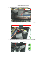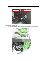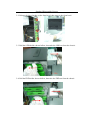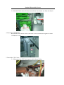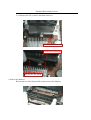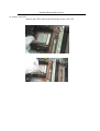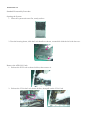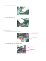
1
Aspire T690
AcerPower FH/SK50
Service Guide
Service guide files and updates are available
on the AIPG/CSD web; for more information,
please refer to http://csd.acer.com.tw
PRINTED IN TAIWAN
Revision History
Please refer to the table below for the updates made on Aspire T690 and AcerPower FH/SK50 service guide.
Date
II
Chapter
Updates
Copyright
Copyright © 2006 by Acer Incorporated. All rights reserved. No part of this publication may be reproduced,
transmitted, transcribed, stored in a retrieval system, or translated into any language or computer language, in
any form or by any means, electronic, mechanical, magnetic, optical, chemical, manual or otherwise, without
the prior written permission of Acer Incorporated.
Disclaimer
The information in this guide is subject to change without notice.
Acer Incorporated makes no representations or warranties, either expressed or implied, with respect to the
contents hereof and specifically disclaims any warranties of merchantability or fitness for any particular
purpose. Any Acer Incorporated software described in this manual is sold or licensed "as is". Should the
programs prove defective following their purchase, the buyer (and not Acer Incorporated, its distributor, or its
dealer) assumes the entire cost of all necessary servicing, repair, and any incidental or consequential
damages resulting from any defect in the software.
Acer is a registered trademark of Acer Corporation.
Intel is a registered trademark of Intel Corporation.
Pentium 4 and Celeron are trademarks of Intel Corporation.
Other brand and product names are trademarks and/or registered trademarks of their respective holders.
III
Conventions
The following conventions are used in this manual:
IV
SCREEN
MESSAGES
Denotes actual messages that appear
on screen.
NOTE
Gives bits and pieces of additional
information related to the current
topic.
WARNING
Alerts you to any damage that might
result from doing or not doing specific
actions.
CAUTION
Gives precautionary measures to
avoid possible hardware or software
problems.
IMPORTANT
Reminds you to do specific actions
relevant to the accomplishment of
procedures.
Preface
Before using this information and the product it supports, please read the following general information.
1.
This Service Guide provides you with all technical information relating to the BASIC CONFIGURATION
decided for Acer's "global" product offering. To better fit local market requirements and enhance product
competitiveness, your regional office MAY have decided to extend the functionality of a machine (e.g.
add-on card, modem, or extra memory capability). These LOCALIZED FEATURES will NOT be covered
in this generic service guide. In such cases, please contact your regional offices or the responsible
personnel/channel to provide you with further technical details.
2.
Please note WHEN ORDERING FRU PARTS, that you should check the most up-to-date information
available on your regional web or channel. If, for whatever reason, a part number change is made, it will
not be noted in the printed Service Guide. For ACER-AUTHORIZED SERVICE PROVIDERS, your Acer
office may have a DIFFERENT part number code to those given in the FRU list of this printed Service
Guide. You MUST use the list provided by your regional Acer office to order FRU parts for repair and
service of customer machines.
V
Chapter1 System Specifications ...............................................1
Features . . . . . . . . . . . . . . . . . . . . . . . . . . . . . . . . . . . . . . . . . 1
Mainboard Placement . . . . . . . . . . . . . . . . . . . . . . . . . . . . . . . 4
Block Diagram . . . . . . . . . . . . . . . . . . . . . . . . . . . . . . . . . . . . 6
Aspire T690 Front Panel . . . . . . . . . . . . . . . . . . . . . . . . . . . . . 7
Aspire T690 Rear Panel . . . . . . . . . . . . . . . . . . . . . . . . . . . . . 8
AcerPower FH Front Panel . . . . . . . . . . . . . . . . . . . . . . . . . . . 9
AcerPower FH Rear Panel . . . . . . . . . . . . . . . . . . . . . . . . . . 10
System Peripherals . . . . . . . . . . . . . . . . . . . . . . . . . . . . . . . . 11
Acer eRecovery . . . . . . . . . . . . . . . . . . . . . . . . . . . . . . . . . . 13
Acer disc-to-disc recovery . . . . . . . . . . . . . . . . . . . . . . . . . . 15
Hardware Specifications and Configurations . . . . . . . . . . . . 16
Power Management Function (ACPI support function) . . . . 21
Chapter2 System Utilities ..........................................................22
About the Setup Utility . . . . . . . . . . . . . . . . . . . . . . . . . . . . .
Product Information . . . . . . . . . . . . . . . . . . . . . . . . . . . . . . .
Standard CMOS Features . . . . . . . . . . . . . . . . . . . . . . . . . . .
Advanced BIOS Features . . . . . . . . . . . . . . . . . . . . . . . . . . .
Advanced Chipset Features . . . . . . . . . . . . . . . . . . . . . . . . .
Integrated Peripherals . . . . . . . . . . . . . . . . . . . . . . . . . . . . .
Power Management Setup . . . . . . . . . . . . . . . . . . . . . . . . . .
PnP/PCI Configurations . . . . . . . . . . . . . . . . . . . . . . . . . . . .
PC Health Status . . . . . . . . . . . . . . . . . . . . . . . . . . . . . . . . .
Frequency Control . . . . . . . . . . . . . . . . . . . . . . . . . . . . . . . .
22
24
25
27
30
32
35
37
38
39
Chapter3 Machine Disassembly and Replacement ................41
General Information . . . . . . . . . . . . . . . . . . . . . . . . . . . . . . . 42
Disassembly Procedure . . . . . . . . . . . . . . . . . . . . . . . . . . . . . 43
Chapter4 Troubleshooting ........................................................64
Chapter5 Jumper and Connector Information ........................65
Main Board Placement . . . . . . . . . . . . . . . . . . . . . . . . . . . . . 65
Jumper Setting . . . . . . . . . . . . . . . . . . . . . . . . . . . . . . . . . . . 67
Chapter6 FRU (Field Replaceable Unit) List ............................74
Exploded Diagram . . . . . . . . . . . . . . . . . . . . . . . . . . . . . . . . 75
FRU List . . . . . . . . . . . . . . . . . . . . . . . . . . . . . . . . . . . . . . . . 77
1
Chapter 1
System Specifications
Features
Processor
T
Socket Type : Intel Socket T LGA 775 pin
T
Processor Type : Intel Prescott 775/Smithfield/Cedar Mill/Presler/Conroe FSB 533/800
Chipset
T
Intel 946GZ+ICH7
T
Form Factor : Mirco ATX
T
Size (Max.) : 244mm x 244mm
PCB
Memory
T
Memory Type : DDRII unbuffered SDRAM module support
T
No. of Channel (Dual/Signal) : Dual channel should be enabled always when plug-in 2 same
memory size DDRII memory module
T
Socket Type : un-buffered 240 pin DIMM socket
T
DIMM Slot : 2
Graphics
T
Onboard graphic solution: Intel 946GZ integrated graphics device solution
T
Dual View function support
T
One VGA port on rear
T
One PCI Express x16 slot
T
One PCI Express x1 slot
T
Two PCI 2.3 Slots
T
Slot Quantity : 1
T
Support 1.44MB 3.5” Devices
T
One 40 pin PATA IDE slot
PCI
FDD
IDE
T
T
Chapter 1
Transfer rate support:
T
PIO mode: 0/1/2/3/4
T
ATA mode: 33/66/100 port supported
Storage type support : HDD/CD-ROM/CD-RW/DVD-ROM/DVD-RW/DVD+RW/DVD Dual/
DVD SuperMultiPlus
1
T
4 pin SATA IDE connector
T
Transfer rate support:
T
T
1.5GB/s and 3.0 GB/s
Storage type support : HDD/CD-ROM/DVD-ROM/DVD-RW/DVD+RW/DVD Dual/DVD
SuperMultiPlus
Audio
T
Audio Type : HD Codec
T
Audio Channel : 7.1 channel
T
Audio Controller /Codec : Realtek ALC888(co-lay with ALC883)
T
Support SPDIF out/in
T
Audio Connectors/Headers:
T
Rear 6 jack follow HD audio definition
T
Microphone In
T
Headphone Out
T
S/PDIF header
T
CD-In
T
AUX-In
LAN
T
Type : Realtek 8100C Gigabit Ethernet controller
T
Supports 10/100/1000MB Ethernet environment
IEEE 1394
T
IEEE 1394 Controller : TI TSB43AB22AG4
T
IEEE 1394 Port : One rear 6pin IEEE 1394 port
T
One header on board
T
Controller : Intel ICH7
T
USB Type : 2.0/1.1
T
Connectors Quantity: 8
USB
T
T
Real Panel : 4
T
Onboard header: 4 for front daughter board, 4 for rear I/O
Standard Intel FPIO pin definition
BIOS
2
T
BIOS Type : Phoenix-Award BIOS
T
4MB Flash BIOS
T
Award PnP BIOS compatible with SM BIOS 2.3
T
ACPI, SMBIOS 2.3, Green and Boot Block.
T
Provides DMI 2.0, WFM 2.0, WOL, and SM Bus for system management.
Chapter 1
I/O Connector
T
Controller : Super I/O ITE 8718
Rear I/O Connector
T
1 PS/2 Keyboard Port, 1 PS/2 Mouse Port
T
1 Parallel Port, 1 Serial Port
T
1 VGA(CRT) Port
T
1 LAN Port
T
4 USB Ports for non-1394 sku; 4 USB ports + IEEE1394 port for 1394 sku
T
7.1 channel phone jack
Onboard Connector
T
1 CPU socket
T
2 Memory slots
T
1 PCI Express x16 slot
T
1 PCI Express x1 slot
T
2 PCI slots
T
1 FDD connector
T
1 PATA IDE slot
T
4 SATA IDE connectors
T
3 2*5 pin Intel FPIO sepcification USB pin connectors.
T
1 2*5 pin Intel FPIO spec. microphone in/headphone out connector
T
1 2*5 pin serial port connector
T
1 CD-IN 4pin connector (CD-ROM Audio Input)
T
1 S/PDIF out 4pin jumper
T
1 4pin CPU Fan connector
T
1 3pin system fan connector with 3pin system fan co-lay
T
1 24pin ATX interface PS3/PS2 SPS connector
T
1 2*7 pin front panel IO header
T
2 reserved 2pin GPIO jumper
T
1 onboard buzzer
T
1 1394 header
T
Color management for on board connecter
Power Supply
T
Chapter 1
PSP Type : 300W
3
Mainboard Placement
No.
4
Description
Name
1
CPU Socket
LGA775 socket for Intel CoreTM2 Duo/Pentium D/Pentium
4/Celeron D CPUs
2
CPU_FAN1
CPU cooling fan connector
3
DIMM1~2
DDR2 240 pin SDRAM slots
4
FDD1
Floppy diskette drive connector
5
ATX1
Standard 24pin ATX power connector
6
IDE1
Primary IDE channel
7
BIOS_WP
BIOS flash protect jumper
8
SATA1~4
Serial ATA connectors
9
JP2
Jumper
10
JP1
Jumper
11
PANEL1
Front panel switch/LED header
12
CLR_CMOS1
Clear CMOS jumper
13
USB3~4
Front panel USB headers
14
1394A1
Onboard 1394a header
15
COM2
Onboard Serial port header
16
SPDIF
SPDIF out header
17
AUDIO2
Front Panel Audio header
Chapter 1
No.
Chapter 1
Description
Name
18
CD_IN1
Analog audio input connector
19
PCI1~2
32 bit add-on card slot
20
PCIEX1
PCI Express x1 slot
21
PCIEX16
PCI Express x16 slot
22
SYS_FAN1
System fan connector
23
R_USB
Front Panel USB header
24
ATX12V1
Auxiliary 4pin power connector
5
Block Diagram
ICH7
PCI LAN
ALC888
SIZE : Max 2GB (Four 512Mb X 8 Double-Sided DEVICES)
DEVICE
IDSEL
INT#
REQ#
GNT#
PCI1
17
C/D/E/F
PREQ-0
PGNT-0
PCI2
18
D/E/F/G
PREQ-1
PGNT-1
1394
19
E
PREQ-2
PGNT-2
LAN
20
F
PREQ-3
PGNT-3
INTEL
P4 Processor
PSC, Tejas LGA 775 pin
BW : 4.1GB/s @ FSB : 533MHz & Freq : 133MHz
BW : 6.4GB/s @ FSB : 800MHz & Freq : 200MHz
BW : 10.7GB/s @ DDR2 :533/667MHz
Analong Display
RAMDAC: 400MHz
INTEL
VGA (G only)
DDIMM1: DDR2 Socket 240P
946GZ
1210pin FC-BGA
Resolutions Up To 2048x1536@75Hz
PCIEx16
DDIMM2 : DDR2 Socket 240P
BW : 2GB/s (Support Lsoch)
USB V2.0
USB1
2 ports
USB2
2 ports
USB3
2 ports
USB4
2 ports
USBLAN
8 ports
Up to Ultra ATA/100
IDE1 40pin
Mic In
Line Out
Line In
CEN/BAS
SURRON
SID SURRON
Audio Codec
Two IDE Channel
PCIEX1
ICH7
609pin EBGA
USBLAN
RJ45
BW : 133MB/s @Freq : 33MHz
PCI1 Slot 120pin @ AD17
PCI2 Slot 120pin @ AD18
AC' 97 & Lan I/F
ALC888
LPC bus
intel
FWH
SATA1 7Pin
SATA2 7pin
SATA3 7Pin
SATA4 7pin
PCIEx1 LAN
BMC5786
INTEL
TI 1394
TSB43AB22
32pin PLCC
BW : 150MB/s
RTL
8100C
ITE 8718
Super I/O
128pin PQFP
USBLAN
RJ45
PCB : 244 x 244 mm ; 4 layers
6
Chapter 1
Aspire T690 Front Panel
The computer’s front panel consists of the following:
No.
Label No.
Description
Chapter 1
Description Description
1
Optical drive
2
Floppy disk drive
3
Power button
4
Speaker or headphone jack
5
Microphone jack
6
USB ports
7
Aspire T690 Rear Panel
No.
Description
No.
8
Description
No.
Description
No.
2
Description
1
Power cord socket
Voltage selector switch
3
Fan aperture
4
PS/2 keyboard connector
5
PS/2 mouse connector
6
Serial port
7
Printer connector
8
Monitor connector
9
USB 2.0 ports
10
RJ-45 Ethernet connector
11
Microphone jack
12
Line-out Jack
13
Line-in jack
14
Extension card slots
Chapter 1
AcerPower FH Front Panel
5
4
3
8
2
7
1
6
Label
Chapter 1
Description
1
Power-Button
2
USB ports
3
Microphone-in & Speaker-out/Line-out Port
4
Optical drive eject button
5
Optical drive
6
Indicators
7
Card reader
8
HDD
9
AcerPower FH Rear Panel
No.
10
No.
Description
Description
No.
Description
No.
Description
1
Power cord socket
2
Voltage selector switch
3
Fan aperture
4
PS/2 keyboard connector
5
PS/2 mouse connector
6
Serial port
7
Printer connector
8
Monitor connector
9
USB 2.0 ports
10
RJ-45 Ethernet connector
11
Microphone jack
12
Line-out Jack
13
Line-in jack
14
Extension card slots
Chapter 1
System Peripherals
The Aspire S Series computer consist of the system itself, and system peripherals, like a
mouse, keyboard and a set of speakers (optional). This section provides a brief description of the basic
system peripherals.
Mouse (PS/2 or USB, manufacturing option)
The included mouse is a standard two-button wheel mouse. Connect the mouse to the PS/2 mouse port or
USB port on the back panel of the system.
Keyboard (PS/2 or USB, manufacturing option)
Connect the keyboard to the PS/2 keyboard port or USB port on the back panel of the system.
Chapter 1
11
Speakers
Note:
For systems bundled with speakers, before powering on the system, connect the speaker cable to the audio
out (external speaker) port on the back panel of the system.
For more detailed information about the speakers, please refer to the included operating instructions.
NOTE: speakers are optional and the appearance might be different depending on the actual product.
12
Chapter 1
Acer eRecovery
Acer eRecovery is a tool to quickly backup and restore the system. Users can create and save a
backup of the current system configuration to hard drive, CD, or DVD.
Acer eRecovery consists of the following functions:
1.
Create backup
2.
Restore from backup
3.
Create factory default image CD
4.
Re-install bundled software without CD
5.
Change Acer eRecovery password
Create backup
Users can create and save backup images to hard drive, CD, or DVD.
1.
Boot to Windows XP
2.
Press <Alt>+<F10> to open the Acer eRecovery utility.
3.
Enter the password to proceed. The default password is six zeros.
4.
In the Acer eRecovery window, select Recovery settings and click Next
5.
In the Recovery settings window, select Backup snapshot image and click Next.
6.
Select the backup method.
T
Use Backup to HDD to store the backup disc image on drive D:.
T
Backup to optical device to store the backup disc image on CD or DVD (only available on
systems that include an optical disc burner).
7.
After choosing the backup method, click Next.
Follow the instruction on screen to complete the process.
Restore from backup
Users can restore backup previously created (as stated in the Create backup section) from hard drive,
CD, or DVD.
1.
Boot to Windows XP.
2.
Press <Alt>+<F10> to open the Acer eRecovery utility.
3.
Enter the password to proceed. The default password is six zeros.
4.
In the Acer eRecovery window, select Recovery actions and click Next.
5.
Select the desired restore action and follow the onscreen instructions to complete the restore process.
Create factory default image CD
When the System CD and Recovery CD are not available, you can create them by using this feature.
1.
Boot to Windows XP.
2.
Press <Alt>+<F10> to open the Acer eRecovery utility.
3.
Enter the password to proceed. The default password is six zeros.
4.
In the Acer eRecovery window, select Recovery settings and click Next.
5.
In the Recovery settings window, select Burn image to disc and click Next.
6.
In the Burn image to disc window, select 01. Factory default image and click Next.
Chapter 1
13
7.
Follow the instructions on screen to complete the process.
Re-install bundled software without CD
Acer eRecovery stores pre-loaded software internally for easy driver and application re-installation.
1.
Boot to Windows XP.
2.
Press <Alt>+<F10> to open the Acer eRecovery utility.
3.
Enter the password to proceed. The default password is six zeros.
4.
In the Acer eRecovery window, select Recovery actions and click Next.
5.
In the Recovery settings window, select Reinstall applications/drivers and click Next.
6.
Select the desired driver/application and follow the instructions on screen to re-install.
At first launch, Acer eRecovery prepares all the needed software and may take few seconds to bring up the
software content window.
Change Password
Acer eRecovery and Acer disc-to-disc recovery are protected by a password that can be changed by
the user. Follow the steps below to change the password in Acer eRecovery.
14
1.
Boot to Windows XP.
2.
Press <Alt>+<F10> to open the Acer eRecovery utility.
3.
Enter the password to proceed. The default password is six zeros.
4.
In the Acer eRecovery window, select Recovery settings and click Next.
5.
In the Recovery settings window, select Password: Change Acer eRecovery password and click Next.
6.
Follow the instructions on screen to complete the process.
Chapter 1
Acer disc-to-disc recovery
Restore without a Recovery CD
This recovery process helps you restore the C: drive with the original software content that is installed when
you purchase your notebook. Follow the steps below to rebuild your C: drive. (Your C: drive will be
reformatted and all data will be erased.) It is important to back up all data files before you use this option.
1.
Restart the system.
2.
While the Acer logo is showing, press <Alt>+<F10> at the same time to enter the recovery process.
3.
The message "The system has password protection. Please enter 000000:" is displayed.
4.
Enter six zeros and continue.
5.
The Acer Recovery main page appears.
6.
Use the arrow keys to scroll through the items (operating system versions) and press <Enter> to select.
Multilingual operating system installation
Follow the instructions to choose the operating system and language you prefer when you first power-on the
system.
1.
Turn on the system.
2.
Acer's multilingual operating system selection menu will pop-up automatically.
3.
Use the arrow keys to scroll to the language version you want. Press <Enter> to confirm your selection.
4.
The operating system and language you choose now will be the only option for future recovery
operations.
5.
The system will install the operating system and language you choose.
Chapter 1
15
Hardware Specifications and Configurations
Processor
Item
Specification
Type
Intel Prescott 775/Smithfield/Cedar Mill/Presler/Conroe
Socket
Socket T LGA 775 pin
Speed
System bus total up to 20.8GB/s
FSB
533/800 MHz
BIOS
Item
Specification
BIOS code programmer
Award
BIOS version
v6.0
BIOS ROM type
Flash ROM
BIOS ROM size
4MB
BIOS ROM package
32-pin DIP package
Support protocol
ACPI 2.0, APM 1.2, SMBIOS 2.3, WFM support, ASD 1.03,
PXE boot ROM, PCI 2.3
Boot from CD-ROM feature
Yes
Support to LS-120 FDD drive
Yes
Support to BIOS boot block feature
Yes
NOTE: The BIOS can be overwritten/upgraded by using the flash utility.
BIOS Hotkey List
Hotkey
Function
Enter BIOS Setup Utility
Delete
Description
Press while the system is booting to
enter BIOS Setup Utility.
Main Board Major Chips
Item
16
Controller
NorthBridge
Intel 946GZ
SourthBridge
Intel ICH7
AGP controller
Intel 946GZ
Super I/O controller
ITE8718
Audio controller
ALC888
LAN controller
Realtek 8100C
HDD controller
ICH7
Keyboard controller
ITE8718
Chapter 1
System Memory
Item
Specification
Memory slot number
2 slot
Support memory size per socket
256MB to 1GB
Support maximum memory size
2GB
Support memory type
DDR2 SDRAM
Support memory interface
DDR2 667/533
Support memory voltage
1.8V
Support memory module package
240-pin DIMM
Support to parity check feature
Yes
Support to Error Correction Code (ECC)
feature
ECC checking with double-bit detect and single-bit
correct
Memory module combinations
You can install memory modules in any combination as
long as they match the specifications.
NOTE: Dual channel should be enabled always when plug-in 2 same memory size DDRII memory module.
Cache Memory
Item
Specification
First-Level Cache Configurations
Cache function control
Enable/Disable by BIOS Setup
Second-Level Cache Configurations
L2 Cache RAM type
PBSRAM
L2 Cache RAM size
up to 1MB per core(exclusive)
L2 Cache RAM speed
One-half the processor core clock frequency
L2 Cache function control
Enable/Disable by BIOS Setup
L2 Cache scheme
Fixed in write-back
Video Interface
Item
Specification
Video controller
Intel ICH7
Video controller resident bus
PCIE
Video Interface
x16
AGP Slot
1
Audio Interface
Item
Specification
Audio controller
ICH7
Audio controller Type
AC’97, ALC888
Audio Channel
7.1ch
Audio function control
Enable/disable by BIOS Setup
Chapter 1
17
Audio Interface
Item
Specification
Mono or stereo
Stereo
Resolution
support up to 24 bit
Compatibility
Sound Blaster Pro/16 compatible
Mixed digital and analog high performance chip
Enhanced stereo full duplex operation
High performance audio accelerator and AC’97 support
Full native DOS games compatibility
Virtual FM enhances audio experience through real-time FM-toWavetable conversion
MPU-401(UART mode) interface for wavetable synthesizers and
MIDI devices
Integrated dual game port
Meets AC’97and WHQL specifications
Music synthesizer
Yes, internal FM synthesizer
Sampling rate
DACs: 44.1k/48k/96k/192k Hz
ADCs: 44.1k/48k/96k Hz
MPU-401 UART support
Yes
Microphone jack
Supported
Headphone jack
Supported
IDE Interface
Item
Specification
IDE controller
Intel ICH7
IDE controller resident bus
PCI bus
Number of IDE channel
1
Support IDE interface
E-IDE (up to PIO mode-4 and Ultra DMA 33/66/100/133), ANSIS
ATA rev.3.0 ATAPI
Support bootable CD-ROM
Yes
Floppy disk drive Interface
Item
18
Specification
Floppy disk drive controller
ITE8718
Floppy disk drive controller resident
bus
LPC bus
Support FDD format
should support 1.44MB/3mode 3.5” Devices
Chapter 1
Parallel Port
Item
Specification
Parallel port controller
ITE8718
Parallel port controller resident bus
ISA bus
Number of parallel ports
1
Support ECP/EPP
Bi-directional SPP / ECP / EPP V1.7&V1.9
Connector type
25-pin D-type female connector
Parallel port function control
Enable/disable by BIOS Setup
Serial Port
Item
Specification
Serial port controller
ITE8718
Serial port controller resident bus
ISA bus
Number of serial port
2
16550 UART support
Yes
Connector type
9-pin D-type female connector
Features
Support IrDA1.0/ASKIR protocols, smart card reader protocols
USB Port
Item
Specification
Universal HCI
USB 2.0
USB Class
Support legacy keyboard for legacy mode
USB Number
support up to 8 ports
Environmental Requirements
Item
Specifications
Temperature
Operating
+5°C ~ +35°C
Non-operating
-20 ~ +60°C (Storage package)
Humidity
Operating
15% to 80% RH
Non-operating
10% to 90% RH
Vibration
Operating (unpacked)
5 ~ 500 Hz:2.20g RMS random, 10 minutes per axis in all 3 axes
5 ~500 Hz: 1.09g RMS random, 1 hour per axis in all 3 axes
Power Management
Devices
Power Button
Chapter 1
S1
(Idle)
S3
(Suspend to
RAM)
S4
(Suspend to
DIsk)
S5
(Shut Down)
Enabled
Enabled
Enabled
Disabled
19
Power Management
Devices
20
S1
(Idle)
S3
(Suspend to
RAM)
S4
(Suspend to
DIsk)
S5
(Shut Down)
USB Keyboard
Enabled
Enabled
Disabled
N/A
LAN
Disabled
Disabled
Disabled
Disabled
RTC
Disabled
Enabled
Disabled
Disabled
Modem (Ring)
Disabled
Disabled
Disabled
N/A
Chapter 1
Power Management Function (ACPI support function)
Device Standby Mode
T
Independent power management timer for hard disk drive devices
(0-15 minutes, time step=1 minute).
T
Hard disk drive goes into Standby mode (for ATA standard interface).
T
Disable V-sync to control the VESA DPMS monitor.
T
Resume method: device activated (Keyboard for DOS, keyboard & mouse for Windows).
T
Resume recovery time: 3-5 sec.
Global Standby Mode
T
Global power management timer (2-120 minutes, time step=10 minute).
T
Hard disk drive goes into Standby mode (for ATA standard interface).
T
Disable H-sync and V-sync signals to control the VESA DPMS monitor.
T
Resume method: Return to original state by pushing external switch button, modem ring in,
keyboard and mouse for APM mode.
T
Resume recovery time: 7-10 sec.
Suspend Mode
T
Independent power management timer (2-120 minutes, time step=10 minutes) or pushing external
switch button.
T
CPU goes into SMM.
T
CPU asserts STPCLK# and goes into the Stop Grant State.
T
LED on the panel turns amber colour.
T
Hard disk drive goes into SLEEP mode (for ATA standard interface).
T
Disable H-sync and V-sync signals to control the VESA DPMS monitor.
T
Ultra I/O and VGA chip go into power saving mode.
T
Resume method: Return to original state by pushing external switch button, modem ring in,
keyboard and mouse for APM mode.
T
Return to original state by pushing external switch button, modem ring in and USB keyboard for
ACPI mode.
T
ACPI specification 1.0b.
T
S0, S1, S3 and S5 sleep state support.
T
On board device power management support.
T
On board device configuration support.
ACPI
Chapter 1
21
Chapter 2
System Utilities
About the Setup Utility
The computer uses the latest Award BIOS with support for Windows Plug and Play. The CMOS chip on the
main board contains the ROM setup instructions for configuring the main board BIOS.
The BIOS Setup Utility displays the system’s configuration status and provides you with options to set system
parameters. The parameters are stored in battery-backed-up CMOS RAM that saves this information when the
power is turned off. When the system is turned back on, the system is configured with the values you stored in
CMOS.
The BIOS Setup Utility enables you to configure:
T
Hard drives, diskette drives and peripheral
T
Video display type and display options
T
Password protection from unauthorized use
T
Power Management features
The settings made in the Setup Utility affect how the computer performs. Before using the Setup Utility, ensure
that you understand the Setup Utility options.
The Standard Configuration
A standard configuration has already been set in the Setup Utility. However, we recommend that you read this
chapter in case you need to make any changes in the future.
This Setup Utility should be used:
Chapter 2
T
when changing the system configuration
T
when a configuration error is detected and you are prompted to make changes to the Setup Utility
T
when trying to revolve IRQ conflicts
T
when making changes to the Power Management configuration
22
Entering the Setup Utility
When you power on the system, BIOS enters the Power-On Self-Test (POST) routines. POST is a series of
built-in diagnostics performed by the BIOS. After the POST routines are completed, the following message
appears: Press DEL to enter SETUP
Press the delete key to have access to the BIOS Setup Utility.
NOTE: If the message disappears before you respond and you still want to enter Setup, restart the system by
turning it OFF and On. You may also restart the system by simultaneously pressing [Ctrl + Alt + Delete].
fProduct Information
fStandard CMOS Features
fAdvanced BIOS Features
fAdvanced Chipset Features
fIntegrated Peripherals
fPower Management Setup
fPnP/PCI Configurations
Esc: Quit
F10: Save & Exit Setup
f PC Health Status
f Frequency/Voltage Control
Load Optimized Defaults
Set Supervisor Password
Set User Password
Save & Exit Setup
Exit Without Saving
mnlk
: Select Item
Time, Date, Hard Disk Type...
BIOS Navigation Keys
The BIOS navigation keys are listed below:
T
ESC: Exits the current menu.
: Scrolls through the items on a menu.
T
T
+/-/PU/PD: Modifies the selected field’s values.
T
F10: Saves the current configuration and exits setup.
T
F1: Displays a screen that describes all key functions.
T
F5: Loads previously saved values to CMOS.
T
F7: Loads an optimum set of values for peak performance.
Using BIOS
When you start the Setup Utility, the main menu will appear. The main menu of the Setup Utility displays a list
of the options that are available. A highlight indicates which options is currently selected. Use the cursor arrow
keys to move the highlight to other options. When an option is highlighted, execute the option by pressing
<Enter>.
Some options lead to pop-up dialog box that prompt you to verify that you want to execute that option. Other
options lead to dialog boxes that prompt you for information.
Some options (marked with a triangle) lead to submenus that enable you to change the values for that option.
Use the cursor arrow keys to scroll through the items in the submenu.
In this chapter, default values are enclosed in parenthesis. Submenu items are denoted by a triangle.
23
Chapter 2
Product Information
This option displays basic information about the system.
Phoenix-AwardBIOS CMOS Setup Utility
Product Information
Product Name
System S/N
Main Board ID
Main Board S/N
System BIOS Version
SMBIOS Version
BIOS Release Date
mnlk : Move
Chapter 2
AST690/APFH/APSK50
R01-A0
E946GZ
Item Help
Menu Level
f
R01-A0
2.3
Jul 27, 2006
Enter: Select +/-/PU/PD:Value F10:Save ESC:Exit F1: General Help
F5:Previous Values
F7:Optimized Defaults
T
Product Names: Displays the model name of your system.
T
System S/N: Displays your system’s serial number.
T
Main Board ID: Displays the ID number of the main board.
T
Main Board S/N: Displays the serial number of the main board.
T
System BIOS Version: Specifies the version of the BIOS utility.
T
SMBIOS Version: The System Management Interface (SM) BIOS allows you to check your
system hardware components without actually opening your system. Hardware checking is done
via software during start up. This parameter specifies the version of the SMBIOS utility installed in
your system.
T
BIOS Release Date: Displays the BIOS latest release date.
24
Standard CMOS Features
Select Standard CMOS Features from the main menu to configure some basic parameters in your system.
Phoenix-AwardBIOS CMOS Setup Utility
Standard CMOS Features
Date (mm:dd:yy) Sun, Jan 1 2006
Time (hh:mm:ss)
9 : 33 : 26
f
f
f
f
f
f
f
f
IDE Channel 0 Master
IDE Channel 0 Slave
IDE Channel 1 Master
IDE Channel 1 Slave
IDE Channel 2 Master
IDE Channel 2 Slave
IDE Channel 3 Master
IDE Channel 3 Slave
[ None]
[LITE-ON DVD SOHD-16F]
[ None]
[ None]
[ST3160612AS]
[ None]
[ None]
[ None]
Video
Halt On
[EGA/VGA]
[All , But Keyboard]
Base Memory
Extended Memory
Total Memory
640K
65535K
1024K
mnlk : Move
Item Help
Menu Level
f
Change the day, month,
year and century
Enter: Select +/-/PU/PD:Value F10:Save ESC:Exit F1: General Help
F5:Previous Values
F7:Optimized Defaults
T
Date and Time: This item shows the current date and time set on the computer. If you are running
a Windows OS, these items are automatically updated whenever you make changes to the
Windows Date and Time Properties utility.
T
IDE Devices (none): Your computer has one IDE channel and can be installed with one or two
devices (Master and Slave). Use this item to configure each device on the IDE channel. This main
board features four SATA connectors supporting four SATA drives. SATA refers to Serial ATA
(Advanced Technology Attachment), the standard interface for the IDE hard drives which are
currently used in most PCs.
Phoenix-AwardBIOS CMOS Setup Utility
IDE Channel 0 Maser
IDE HDD Auto-Detection
[Press Enter]
IDE Channel 0 Master
Access Mode
[Auto]
[Auto]
Capacity
0 MB
Cylinder
Head
Precomp
Landing Zone
Sector
0
0
0
0
0
mnlk : Move
25
Item Help
Menu Level
ff
To auto-detect the
HDD’s size, head... on
this channel
Enter: Select +/-/PU/PD:Value F10:Save ESC:Exit F1: General Help
F5:Previous Values
F7:Optimized Defaults
Chapter 2
IDE HDD Auto-Detection: Press <Enter> while this item is highlighted to prompt the Setup
Utility to automatically detect and configure an IDE device on the IDE channel.
NOTE: Press <Enter> while this item is highlighted to prompt the Setup Utility to automatically detect and
configure an IDE device on the IDE channel.
T
Chapter 2
T
IDE Channel 0/1/2/3 Master/Slave IDE/Extended IDE Drives (Auto): Leave this item Auto to
enable the system to automatically detect and configure IDE devices on the channel. If it fails
to find a device, change the value to Manual and then manually configure the drive by
entering the properties of the drive in the items described below. Please note that if you
choose IDE channel 2/3 Master, the item may change to Extended IDE drive.
T
Access Mode: This item defines ways that can be used to access IDE hard disks such as
LBA (Large Blocking Addressing). Leave this value Auto and the system will automatically
decide the fastest way to access the hard disk drive. If you choose IDE channel 2/3 Master,
the item only has Large and Auto.
T
Video (EGA/VGA): This item defines the video mode of the system. This main board has a built-in
VGA graphics system. You must leave this item at the default value.
T
Halt On (All but Keyboard): This item defines the operation of the system POST (Power-On SelfTest) routine. You can use this item to select which types of errors in the POST are sufficient to
halt the system.
T
Base Memory, Extended Memory, and Total Memory: This items are automatically detected by
the system at start up time. These are display-only fields. You can not make changes to these
fields.
26
Advanced BIOS Features
The following screen shows the Advanced BIOS Features.
Phoenix-AwardBIOS CMOS Setup Utility
Advanced BIOS Features
f CPU Feature
f Hard Disk Boot Priority
Virus Warning
CPU L1 & L2 Cache
Hyper-Threading Technology
Quick Power On Self Test
First Boot Device
Second Boot Device
Third Boot Device
Boot Other Device
Boot Up NumLock Status
Gate A20 Option
Typematic Rate Setting
x Typematic Rate (Chars/Sec0
x Typematic Delay (Msec)
Security Option
x APIC Mode
MPS Version Control For OS
OS Select For DRAM > 64MB
mnlk : Move
T
[Press Enter]
[Press Enter]
[Disabled]
[Enabled]
[Enabled]
[Enabled]
[Floppy]
[Hard Disk]
[CDROM]
[Enabled]
[On]
[Fast]
[Disabled]
6
250
[Setup]
Enabled
[1.4]
[Non-OS2]
Item Help
Menu Level f
12
12
12
12
Enter: Select +/-/PU/PD:Value F10:Save ESC:Exit F1: General Help
F5:Previous Values
F7:Optimized Defaults
CPU Features (Press Enter): Please note that this function is only available for Prescott CPUs.
Scroll to this item and press <Enter> to view the following screen.
Phoenix-AwardBIOS CMOS Setup Utility
CPU Feature
x
x
Delay Prior to Thermal
Thermal Management
TM2 Bus Ratio
TM2 Bus VID
Limit CPUID MaxVal
CPU Enhanced Halt (C1E)
Execute Disable Bit
mnlk : Move
27
[16 Min]
[Thermal Monitor 1]
12 X
1.2000V
[Disabled]
[Auto]
[Enabled]
Item Help
Menu Level
ff
Enter: Select +/-/PU/PD:Value F10:Save ESC:Exit F1: General Help
F5:Previous Values
F7:Optimized Defaults
Chapter 2
T
T
Delay Prior to Thermal (16 Min): This item enables you to set the delay time before the CPU
enters auto thermal mode.
T
Thermal Management (Thermal Monitor 1): This item displays CPU’s temperature and
enables you to set a safe temperature to Prescott CPU.
T
TM2 Bus Ratio (12X): This item represents the frequency (bus ratio) of the throttled
performance state that will be initiated when the on-die sensor goes from not hot to hot.
T
TMS Bus VID (1.2000V): This item represents the voltage of the throttled performance state
that will be initiated when the on-die sensor goes from not hot to hot.
T
Limit CPUID MaxVal (Disabled): This item can support Prescott CPUs for old OS. Please
note that under NT4.0, it must be set Enabled while under WinXP, it must be set Disabled.
T
Execute Disable Bit (Enabled): This item is a security feature that helps you protect your
CPU and operating system against malicious software executing code. This item is available
when CPU supports the feature.
Hard Disk Boot Priority (Press Enter): Scroll to this item and press <Enter> to view the following
screen.
Phoenix-AwardBIOS CMOS Setup Utility
Hard Disk Boot Priority
1. Ch2 M.
: ST3160812AS
2. Bootable Add-in Cards
Item Help
Menu Level ff
Use < m > or < n > to
select a device, then
press <+> to move it
up, or <-> to move it
down the list. Press
<ESC> to exit this
menu.
mnlk : Move
Chapter 2
Enter: Select +/-/PU/PD:Value F10:Save ESC:Exit F1: General Help
F5:Previous Values
F7:Optimized Defaults
T
Virus Warning (Disabled): This item is used to enable or disable virus warning function.
T
CPU L1 & L2 Cache (Enabled): All processors that can be installed in this main board use
internal level 1 (L1) and external level 2 (L2) cache memory to improve performance. Leave this
item at the default value for better performance.
T
Hyper-Threading Technology (Enabled): This item is only available when the chipset supports
Hyper-Threading and you are using a Hyper-Threading CPU.
T
Quick Power On Self Test (Enabled): Enable this item to shorten the power on testing (POST)
and have your system start up faster. You might like to enable this item after you are confident that
your system hardware is operating smoothly.
T
First/Second/Third Boot Device (Floppy/Hard Disk/CD ROM): Use these three items to select
the priority and order of the devices that your system searches for an operating system at start-up
time.
T
Boot Other Device (Enabled): When enabled, the system searches all other possible locations
for an operating system if it fails to find one in the devices specified under the First, Second and
28
Third boot devices.
29
T
Boot Up NumLock Status (On): This item defines if the keyboard NumLock key is active when
your system is started.
T
Gate A20 Option (Fast): This item defined how the system handles legacy software that was
written for an earlier generation of processors. Leave this item at the default value.
T
Typematic Rate Setting (Disabled): If this item is enabled, you can use the following two items to
set the typematic rate and the typematic delay settings for your keyboard.
T
Typematic Rate (Chars/Sec): Use this item to define how many characters per second are
generated by held-down key.
T
Typematic Delay (Msec): Use this item to define how many milliseconds must elapse before
a held-down key begins generating repeat characters.
T
Security Option (Setup): If you have installed password protection, this item defines if the
password is required at system start up, or if it is only required when a user tries to enter the Setup
Utility.
T
APIC Mode (Enable): This item allows you to enable or disable the APIC (Advanced
Programmable Interrupt Controller) mode. APIC provides symmetric multi-processing (SMP) for
systems, allowing support for up to 60 processors.
T
MPS Version Control For OS (1.4): This item displays MPS version control for OS.
T
OS Select For DRAM > 64MB (Non-OS2): This item is only required if you have installed more
than 64MB of memory and you are running the OS/2 operating system. Otherwise, leave this item
at the default.
T
HDD S.M.A.R.T Capability (Disabled): When you enable HDD SMART (Self-Monitoring, Analysis
and Reporting Technology) Capability, these new BIOSes will automatically check the hard disk’s
SMART status at boot-up.
T
Report No FDD For WIN 95 (Disabled): Set this item to the default if you are running a system
with no floppy drive and using Windows 95. This ensures compatibility with the Window 95 logo
certification.
T
Silent Boot (Enabled): If enabled, BIOS will show a full screen logo at boot. If disabled, BIOS will
set the initial display mode to BIOS and show the diagnostic POST screen at boot.
T
Small Logo (EPA) Show (Disabled): This item enabled or disables the display of the EPA logo
during boot.
T
Configuration Table (Disabled): Use this item to show summary screen.
Chapter 2
Advanced Chipset Features
These items define critical timing parameters of the main board. You should leave the items on this page at
their default values unless you are very familiar with the technical specifications of your system hardware. If
you change the values incorrectly, you may introduce fatal errors or recurring instability into your system.
Phoenix-AwardBIOS CMOS Setup Utility
Advanced Chipset Feature
System BIOS Cacheable
Video BIOS Cacheable
Memory Hole At 15M-16M
f PCI Express Root Port Func
** VGA Setting **
PEG/Onchip VGA Control
On-Chip Frame Buffer Size
DVMT Mode
DVMT/FIXED Memory Size
mnlk : Move
Chapter 2
[Enabled]
[Disabled]
[Disabled]
[Press Enter]
Item Help
Menu Level
f
[Auto]
[ 8MB]
[DVMT]
[ 128MB]
Enter: Select +/-/PU/PD:Value F10:Save ESC:Exit F1: General Help
F5:Previous Values
F7:Optimized Defaults
T
System BIOS Cacheable (Enable): This item allows the system to be cached in memory for
faster execution. Enable this item for better performance.
T
Video BIOS Cacheable (Disabled): This item aims to further boost the performance of a
shadowed video BIOS by caching it using the processor’s Level 2 cache.
T
Memory Hole At 15M-16M (Disable): In order to improve performance, certain space in memory
can be reserved for ISA cards. This memory must be mapped into the memory space below
16MB.
30
T
PCI Express Root Port Func (Press Enter): Scroll to this item and press <Enter> to view the
following screen.
Phoenix-AwardBIOS CMOS Setup Utility
PCI Express Root Port Func
PCI Express Port 1
PCI Express Port 2
PCI Express Port 3
PCI Express Port 4
PCI Express Port 5
PCI Express Port 6
PCI-E Compliancy Mode
mnlk : Move
T
31
[Auto]
[Auto]
[Auto]
[Auto]
[Auto]
[Auto]
[v1.0a]
Item Help
Menu Level
ff
Enter: Select +/-/PU/PD:Value F10:Save ESC:Exit F1: General Help
F5:Previous Values
F7:Optimized Defaults
PCI-E Compliancy Mode (1.0a): This item allows you to select the PCI-E Compliancy mode.
T
PEG/Onchip VGA Control (Auto): This item allows you to control the PEG or on-chip VGA.
T
On-Chip Frame Buffer Size (8MB): This item controls the amount of system memory that is
allocated to the integrated graphics processor when the system boots up.
T
DVMT Mode (DVMT): this item allows you to select the DVMT operating mode.
T
PEG/On-chip VGA Control (128MB): This item allows you to adjust the shared memory size.
Chapter 2
Integrated Peripherals
These options display items that define the operation of peripheral components on the system’s input/output
ports.
Phoenix-AwardBIOS CMOS Setup Utility
Integrated Peripherals
f OnChip IDE Device
f Onboard Device
f SuperIO Device
mnlk : Move
T
[Press Enter]
[Press Enter]
[Press Enter]
Item Help
Menu Level
ff
Enter: Select +/-/PU/PD:Value F10:Save ESC:Exit F1: General Help
F5:Previous Values
F7:Optimized Defaults
Onboard Device (Press Enter): Scroll to this item and press <Enter> to view the following screen.
Phoenix-AwardBIOS CMOS Setup Utility
Onboard Device
IDE HDD Block Mode
IDE DMA transfer access
OnChip Primary PCI IDE
IDE Primary Master
IDE Primary Slave
IDE Primary Master
IDE Primary Slave
OnChip Secondary PCI IDE
IDE Secondary Master
IDE Secondary Slave
IDE Secondary Master
IDE Secondary Slave
PIO
PIO
UDMA
UDMA
PIO
PIO
UDMA
UDMA
*** On-Chip Serial ATA Setting ***
OnChip Serial ATA
mnlk : Move
T
Chapter 2
[Enabled]
[Enabled]
[Enabled]
[Auto]
[Auto]
[Auto]
[Auto]
[Enabled]
[Auto]
[Auto]
[Auto]
[Auto]
Item Help
Menu Level
ff
If your IDE hard drive
supports block mode
select Enabled for
automatic detection of
the optimal number of
block read/writes per
sector the drive can
support
[Enabled]
Enter: Select +/-/PU/PD:Value F10:Save ESC:Exit F1: General Help
F5:Previous Values
F7:Optimized Defaults
IDE HDD Block Mode (Enabled): If your IDE hard drive supports block mode, select Enabled
for automatic detection of the optimal number of block read/write per sector that the drive can
support.
32
T
T
IDE DMA transfer access (Enabled): This item allows you to enable the transfer access of
the IDE DMA then burst onto the PCI bus and nonburstable transactions do not.
T
OnChip Primary/Secondary PCI IDE (Enabled): Use these items to enable or disable the
PCI IDE channels that are integrated on the main board.
T
Primary/Secondary Master/Slave UltraDMA (Auto): Enable this item if you plan to use a
mouse connected through the USB port in a legacy operating system (such as DOS) that
does not support Plug and Play.
T
OnChip Serial ATA (Enabled): Use this item to enable or disable the on-chip serial ATA.
Onboard Device (Press Enter): Scroll to this item and press <Enter> to view the following screen.
Phoenix-AwardBIOS CMOS Setup Utility
Onboard Device
USB Controller
USB 2.0 Support
USB Keyboard Support
USB Mouse Support
Onboard Audio Device
Onboard IEEE1394 Controller
Onboard GLAN Device
Onboard Lan Boot ROM
mnlk : Move
33
[Enabled]
[Enabled]
[Disabled]
[Disabled]
[Enabled]
[Enabled]
[Enabled]
[Enabled]
Item Help
Menu Level
ff
Enter: Select +/-/PU/PD:Value F10:Save ESC:Exit F1: General Help
F5:Previous Values
F7:Optimized Defaults
T
USB Controller (Enabled): Enables or disables the onboard USB controller. We recommend
users keep the default value. It might cause the USB devices not to work properly if you
disable this item.
T
USB 2.0 Support (Enabled): This item enables or disables the onboard USB 2.0 controller.
T
USB Keyboard Support (Disabled): Enable this item if you want to use a keyboard
connected through the USB port in a legacy operating system (such as Dos) that does not
support Plug and Play.
T
USB Mouse Support (Enabled): Enable this item if you want to use a mouse connected
through the USB port in a legacy operating system (such as DOS) that does not support Plug
and Play.
T
Onboard Audio Device (Enabled): Use this item to enable or disable the onboard audio
device.
T
Onboard IEEE 1394 Controller (Enabled): This item allows you to control the onboard IEEE
1394 controller.
T
Onboard GLAN Device (Enabled): Use this item to enable or disable the onboard GLAN
device.
T
Onboard Lan Boot ROM (Enabled): Use this item to enable or disable the booting from the
onboard LAN or a network add-in card with a remote boot TOM installed.
Chapter 2
Super IO Device (Press Enter): Scroll to this item and press <Enter> to view the following screen.
T
p
g
Phoenix-AwardBIOS CMOS Setup Utility
Super IO Device
x
Onboard FDC Controller
Onboard Serial Port 1
Onboard Serial Port 2
Onboard Parallel Port
Parallel Port Mode
ECP Mode Use DMA
[Enabled]
[3F8/IRQ4]
[2F8/IRQ3]
[378/IRQ7]
[SPP]
3
Item Help
Menu Level ff
mnlk : Move
Enter: Select +/-/PU/PD:Value F10:Save ESC:Exit F1: General Help
F5:Previous Values
F6:Fail-Safe Defaults
F7:Optimized Defaults
Chapter 2
T
Onboard FDC Controller (Enabled): Select Enabled if your system has a floppy disk
controller (FDC) installed on the main board. If you install an add-in FDC or the system has no
floppy drive, select Disabled in this field.
T
Onboard Serial Port 1/2 (3F8/IRQ4/2F8/IRQ3): These options are used to assign the I/O
address and interrupt request (IRQ) for onboard serial port 1 and port 2.
T
Onboard Parallel Port (378/IRQ7): This option is used to assign the I/O address and
interrupt request (IRQ) for the onboard parallel port.
T
Parallel Port Mode (SSP): Enables you to set the data transfer protocol for your parallel port.
There are four options: SPP (Standard Parallel Port), EPP (Enhanced Parallel Port), ECP
(Extended Capabilities Port), and ECP + EPP.
T
ECP Mode Use DMA (3): When the onboard parallel port is set to ECP mode, the parallel port
can use DMA 3/1.
34
Power Management Setup
This option lets you control system power management. The system has various power-saving modes
including powering down the hard disk, turning off the video, suspending on RAM, and software power down
that allows the system to be automatically resumed by certain events.
mnlk : Move
35
[Enabled]
[S3(STR)]
[Auto]
[User Define]
[DPMS]
[Yes]
[Stop Grant]
[3]
[Disabled]
[Disabled]
[Delay 4 Sec.]
[Enabled]
[Enabled]
[Enabled]
[Enabled]
[Enabled]
[Former-Sts]
[Disabled]
Item Help
Menu Level
f
123
123
123
f
ACPI Function
ACPI Suspend Type
Run VGABIOS if S3 Resume
Power Management
Video Off Method
Video Off In Suspend
Suspend Type
MODEM Use IRQ
Suspend Mode
HDD Power Down
Soft-Off by PWR-BTTN
Resume by PCI PME
Resume by Ring
S3 resume by USB devices
Resume by PS2 MS (S3)
Resume by PS2 KB (S3)
Power on After Power Fail
Resume by Alarm
f
Phoenix-AwardBIOS CMOS Setup Utility
Power Management Setup
Enter: Select +/-/PU/PD:Value F10:Save ESC:Exit F1: General Help
F5:Previous Values
F7:Optimized Defaults
T
ACPI Function (Enabled): Use this item to enable or disable the ACPI function.
T
ACPI Suspend Type (S3(STR)): Use this item to define how your system suspends. In the
default, S3 (STR), the suspend mode is a suspend on RAM, i.e., the system shuts down with the
exception of a refresh current to the system memory.
T
Run VGA BIOS if S3 Resume (Auto): This item allows the system to initialize the VGA BIOS from
S3 (Suspend on RAM) sleep state.
T
Power Management (User Define): Use this item to enable or disable a power management
scheme. If you enable power management, you can use the items below to set the power
management operation.
T
Video Off Method: This item defines how the video is powered down to save power. This item is
set for DPMS (Display Power Management Software) by default.
T
Suspend Type (Stop Grant): If this item is set to the default Stop Grant, the CPU will go into Idle
Mode during power saving power.
T
Modem Use IRQ (3): If you want an incoming call on a modem to automatically resume the
system from a power-saving mode, use this item to specify the interrupt request line (IRQ) that is
used by the modem. You might have to connect the fax/modem to the main board Wake On
Modem connector for the feature to work.
T
Suspend Mode (Disabled): This item allows you to enable or disable the suspend mode.
T
HDD Power Down (Disabled): The IDE hard drive will spin down if it is not accessed within a
specified length of time.
T
Soft-Off by PWR-BTTN (Instant-Off): Under ACPI (Advanced Configuration and Power
Management Interface) you can create a software power down. In a software power down, the
system can be resumed by Wake Up Alarms. This item lets you install a software power down that
is controlled by the power button on your system. If the item is set for Instant-Off, then the power
button causes a software power down. If the item is set for Delay four Sec., then you have to hold
Chapter 2
the power button down for four seconds to cause a software power down.
Chapter 2
T
Resume by PCI PME (Enabled): This item specifies whether the system will be awakened from
power-saving modes when activity or input signal of the specified hardware peripheral or
component is detected.
T
Resume by Ring (Enabled): An input signal on the serial Ring indicator (RI) line (in other words,
an incoming call on the modem) awakens the system from soft off state.
T
S3 resume by USB devices (Disabled): This option allows the activity of the USB devices
(keyboard and mouse) to wake up the system from S3 sleep state.
T
Resume by PS2 MS/KS (S3) (Disabled): Enable or disable the function of waking up the system
by the mouse/keyboard activity.
T
Power on After Power fail (Off): This item enables your computer to automatically restart or
return to its last operating status after power returns from a power failure.
T
Resume by Alarm (Disabled): When it is set to Enabled, additional fields become available and
you can set the data (day of the month), hour, minute and second to turn on your system. When it
is set to zero for the day of the month, the alarm will power on your system every day at the
specified time.
T
**Reload Global Timer Events**: Global Timer (power management) events are I/O events
whose occurrence can prevent the system from entering a power saving mode or can awaken the
system from such a mode. In effect, the system remains alert for anything that occurs to a device
that is configured as Enabled, even when the system is in a power-down mode.
T
Primary/Secondary IDE 1/0 (Disabled): When these items are enabled, the system will restart
the power-saving timeout counters when any activity is detected on any of the drives or devices on
the primary or secondary IDE channels.
T
FDD, COM, LPT Port (Disabled): When this item is enabled, the system will restart the powersaving timeout counters when any activity is detected on the floppy disk drive, serial ports, or the
parallel port.
T
PCI PIRQ[A-D]# (Disabled): When this item is enabled, any activity from one of the listed devices
wakes up the system.
36
PnP/PCI Configurations
This options configure how PnP (Plug and Play) and PCI expansion cards operate in your system. Both the
ISA and PCI buses on the main board use system IRQs (Interrupt ReQuests) and DMAs (Direct Memory
Access). You must set the IRQ and DMA assignments correctly through the PnP/PCI Configurations Setup
utility for the main board to work properly. Selecting PnP/PCI Configurations on the main board program
screen displays this menu:
Phoenix-AwardBIOS CMOS Setup Utility
PnP/PCI Configurations
Init Display First
Reset Configuration Data
[PCI Slot]
[Disabled]
Item Help
Menu Level
Resources Controlled By
X IRQ Resources
PCI/VGA Palette Snoop
Assign IRQ For USB
INT Pin 1 Assignment
INT Pin 2 Assignment
INT Pin 3 Assignment
INT Pin 4 Assignment
INT Pin 5 Assignment
INT Pin 6 Assignment
INT Pin 7 Assignment
INT Pin 8 Assignment
[Auto(ESCD)]
Press Enter
f
[Disabled]
[Auto]
[Auto]
[Auto]
[Auto]
[Auto]
[Auto]
[Auto]
[Auto]
[Auto]
** PCI Express relatvie items**
Maximum Payload Size
[4096]
mnlk : Move
T
Init Display First (PCI Slot): This item allows you to choose the primary display card.
T
Reset Configuration Data (Disabled): If you enable this item and restart the system, any Plug
and Play configuration data stored in the BIOS Setup is cleared from memory.
T
Resources Controlled by (Auto (ESCD)): You should leave this item at the default Auto (ESCD).
Under this setting, the system dynamically allocates resources to Plug and Play devices as they
are required.
T
37
Enter: Select +/-/PU/PD:Value F10:Save ESC:Exit F1: General Help
F5:Previous Values
F7:Optimized Defaults
IRQ Resources: In the IRQ Resources submenu, if you assign an IRQ to Legacy ISA, then
that Interrupt Request Line is reserved for a legacy ISA expansion card. Press <Esc> to close
the IRQ Resources submenu. In the Memory Resources submenu, use the first item
Reserved Memory Base to set the start address of the memory you want to reserve for the
ISA expansion card. Use the section item Reserved Memory Length to set the amount of
reserved memory. Press <Esc> to close the Memory Resources submenu.
T
PCI/VGA Palette Snoop (Disabled): This item is designed to overcome problems that can be
caused by some non-standard VGA cards. This board includes a built-in VGA system that does
not require palette snooping so you must leave this item disabled.
T
Assign IRQ for USB (Enabled): This item enables or disables IRQ allocation for the USB.
T
INT Pin 1-8 Assignment (Auto): Identifies the interrupt request (IRQ) line assigned to a device
connected to the PCI interface of the system.
T
Maximum Payload Size (4096): This item specifies the maximum TLP payload size for the PCI
Express devices. The unit is byte.
Chapter 2
PC Health Status
On the main boards that support hardware monitoring, this item lets you monitor the parameters for critical
voltages, temperatures, and fan speeds.
Phoenix-AwardBIOS CMOS Setup Utility
PC Health Status
Smart Fan Control
[Enabled]
CPU Warning Temperature [70°C/158°F]
Vcore
1.20V
+3.3V
3.37V
+5V
4 .94V
+12V
11.45V
5V SB
4.94V
Current CPU Temperature 36°C
Current System Temperature 30°C
Current CPU fan Speed
0 RPM
Current System fan Speed 0 RPM
mnlk : Move
Chapter 2
Item Help
Menu Level
f
Enter: Select +/-/PU/PD:Value F10:Save ESC:Exit F1: General Help
F5:Previous Values
F7:Optimized Defaults
T
Smart Fan Control (Enabled): This item enables or disables the Smart fan function, when it is set
at certain temperature, the PWN value will reach the certain value accordingly, and we can adjust
the CPU fan speed by PWN.
T
CPU Warning Temperature (70oC/158oF): Enable you to manually set the warning temperature
of the system.
T
System Component Characteristics: These field provide you with information about the
systems.
38
Frequency Control
This item enables you to set the clock speed and system bus for your system. The clock speed and system
bus are determined by the kind of processor you have installed in your system.
Phoenix-AwardBIOS CMOS Setup Utility
Frequency Control
CPU Clock Ratio
[17X]
Item Help
Menu Level
mnlk : Move
T
39
f
Enter: Select +/-/PU/PD:Value F10:Save ESC:Exit F1: General Help
F5:Previous Values
F7:Optimized Defaults
CPU Clock Ratio (25X): Enables you to set the CPU clock.
Chapter 2
Load Fail-Safe Defaults Option
This option opens a dialog box that lets you install fail-safe defaults to all appropriate items in the Setup Utility:
Press <Y> and the <Enter> to install the defaults. Press <N> and then <Enter> to not install the defaults. The
Fail-Safe defaults place no great demands on the system and are generally stable. If your system does not
function correctly, try to install the Fail-Safe Defaults as a first step for making your system work properly
again. If you only want to install Fail-Safe Defaults for a specific option, select and display that option, and then
press <F6>.
Load Optimized Defaults Option
This option opens a dialog box that lets you install optimized defaults for all appropriate items in the Setup
Utility. Press <Y> and then <Enter> to install the defaults. Press <N> and then <Enter> to not install the
defaults. The optimized defaults place demands on the system that may be greater than the performance level
of the components, such as the CPU and the memory. You can cause fatal errors or instability if you install the
optimized defaults when your hardware does not support them. If you only want to install setup defaults for a
specific option, select and display that option, and then press <F7>.
NOTE: Please remain the factory BIOS default setting of Load optimized Defaults when you install
Operation System onto the unit.
Set Supervisor/User Password
Type the password, up to eight characters and press <Enter>. The new password will clear any previously
entered password from CMOS memory. You will be asked to confirm the password. Type the new password
again and press <Enter>. You may also press <Esc> to abort the selection.
To disable password, just press <Enter> when you are prompted to enter password. A message will confirm
the password being disabled. Once the password is disabled, the system will boot and you can enter BIOS
Setup freely.
If you have selected System in Security Option of BIOS Features Setup menu, you will be prompted for the
password every time the system reboots or any time you try to enter BIOS Setup.
If you have selected Setup in Security Option from BIOS Features Setup menu, you will be prompted for the
password only when you enter BIOS Setup.
Supervisor Password has higher priority than User Password, You can use Supervisor Password when
booting the system or entering BIOS Setup to modify all settings. Also you can use User Password when
booting the system or entering BIOS Setup but can not modify any setting if Supervisor Password is enabled.
Save & Exit Setup
Highlight this item and press <Enter> to save the changes that you have made in the Setup Utility and exit the
Setup Utility. When the Save and Exit dialog box appears, press <Y> to save and exit, or press <N> to return
to the main menu.
Exit without Saving
Highlight this item and press <Enter> to discard any changes that you have made in the Setup Utility and exit
the Setup Utility. When the Exit without Saving dialog box appears, press <Y> to discard changes and exit, or
press <N> to return to the main menu.
NOTE: If you have made settings that you do not want to save, use the Exit with Saving item and press <Y>
to discard any changes you have made.
Chapter 2
40
Chapter 3
Machine Disassembly and Replacement
To disassemble the computer, you need the following tools:
T
Wrist grounding strap and conductive mat for preventing electrostatic discharge.
T
Wire cutter.
T
Phillips screwdriver (may require different size).
NOTE: The screws for the different components vary in size. During the disassembly process, group the
screws with the corresponding components to avoid mismatches when putting back the components.
Chapter 3
41
General Information
Before You Begin
Before proceeding with the disassenbly procedure, make sure that you do the following:
42
1.
Turn off the power to the system and all peripherals.
2.
Unplug the AC adapter and all power and signal cables from the system.
Chapter 3
Disassembly Procedure
This section tells you how to disassemble the system when you need to perform system service. Please also
refer to the disassembly video, if available.
CAUTION: Before you proceed, make sure you have turned off the system and all peripherals connected to it.
Chapter 3
43
Aspire T690 Standard Disassembly Process
1. Open the computer.
1-1. Place the system unit on a flat, steady surface.
1-2. Turn the housing down, release the Lock-handle then slide the left side door
2. Disconnect the cables.
2-1. Disconnect the AUDIO cable.
Standard Disassembly Process
2-2. Disconnect the USB and Front LED ASSY cables.
Front LED ASSY cable
USB Cable
Card-reader Cable
2-3 . Disconnect the PA and PD power-cable from the MB connector.
PA power-connector
PD power-connector
2-4 . Disconnect the P1 power-cable and ODD data cable from the MB connector.
P1 power-cable
ODD data cable
Standard Disassembly Process
2-5 . Disconnect FDD data cable from the MB connector.
FDD data cable
2-6 . Disconnect the ODD data cable and power-cable from the rear of ODD.
ODD data cable
ODD power-cable
2-7 . Disconnect the FDD data cable and power-cable from the rear of FDD.
FDD power-cable
FDD data cable
Standard Disassembly Process
2-8 . Disconnect the HDD data cable and power-cable from the rear of HDD and MB.
HDD data Cable
HDD power-cable
3. Detach the HDD, FDD and ODD.
3-1. Rail the HDD-holder shown bellow, then take the HDD out from the chassis.
Standard Disassembly Process
3-2. Release the three latches on the front bezel, then remove the front bezel.
3-3. Rail the ODD-holder shown bellow, then take the ODD out from the chassis.
3-4. Rail the FDD-holder shown bellow, then take the FDD out from the chassis.
Standard Disassembly Process
3-5. Rail the Holder shown bellow, then take the Card-reader out from the chassis.
4. Detach the USB Module.
Release the screw shown bellow, then take off the USB module together with the
USB&Audio cable.
5. Detach the CPU Cooler.
5-1. Disconnect the CPU Cooler power-cable shown bellow.
Standard Disassembly Process
5-2. Release the CPU Cooler Latch then remove it.
Before revolve the Latch
Pull the Latch afterward
After revolve the Latch
6. Remve the Memory.
Release the two latch shown bellow then remove the Memory.
Standard Disassembly Process
7. Remve the System Fan.
Release the four screws shown bellow then take off the fan.
8. Remove the Motherboard.
Release the eight screws shown bellow then take off the MB.
9. Remove the Power-supply.
Release the four screws shown bellow then take off the Power-supply.
Standard Disassembly Process
10. Remove the CPU.
Release the CPU Latch on the Socket then remove the CPU.
AcerPower FH
!
"
#
"
"
$
%&
&'!
()$!
#
()$ &
"
*
"
#
+
"
#
#
&
(
&
,
'-
$. '
$. ' &
'- &
. /
&
!
&
. /&
&
&
!
*
(
0
1
& .
,2/
& .
(
0
+
+
4
6
0 31
' 3
-
1
0 -1
5
#
-
#
7
0 /1
9
8
:
3
<
8
$ $
$
;
8
,2/ &
,2/ &
0 &1
,2/
# 8
5-
' 3
,2/
-
' 3
"
#
,
',,
"
#
8
#
"
#
"
8
=
=
#
=
"
#
"
& !" , 8 !8
&
!
8
"
8
!8
*
"
-
!8
&
!
,
+
"
-
!8
&
!
,
8
# 8
"
"
!8
#
"
#
. /,
#
. /,
. /
"
#
"
"
'- ,
#
#
"
,
#
#
#
. /5$
"
#
"
"
,
#
#
"
#
,
!
#
#
!
Chapter 4
Troubleshooting
Please refer to generic troubleshooting guide for trougleshooting information relating to following topics:
Chapter 4
T
Power-On Self-Test (POST)
T
POST Check Points
T
POST Error Messages List
T
Error Symptoms List
64
Chapter 5
Jumper and Connector Information
Main Board Placement
#
Label
Description
#
Label
Description
1
CPU Socket
LGA775 socket for Intel
CoreTM Duo / Pentium D /
Pentium 4 / Celeron D CPUs
2
CPU_FAN1
CPU cooling fan connector
3
DIMM1~2
DDR2 240 pin SDRAM slots
4
FDD1
Floppy diskette drive
connector
Chapter 5
65
#
Label
Description
#
Label
Description
5
ATX1
Standard 24-pin ATX power
connector
6
IDE1
Primary IDE channel
7
BIOS_WP
BIOS flash protect jumper
8
SATA1~4
Serial ATA connectors
9
JP2
TBD
10
JP1
TBD
11
PANEL1
Front Panel switch/LED
header
12
CLR_CMOS1
Clear CMOS jumper
13
USB3~4
Front Panel USB headers
14
1394a1
Onboard 1394a header
15
COM2
Onboard Serial port header
16
SPDIF
SPDIF out header
17
AUDIO2
Front Panel Audio header
18
CD_IN1
Analog audio input connector
19
PCI1~2
32-bit add-on card slots
20
PCIEX1
PCI Express x1 slot
21
PCIEX16
PCI Express x16 slot
22
SYS_FAN1
System fan connector
23
R_USB
Front Panel USB header
24
ATA12V1
Auxiliary 4-pin power
connector
66
Chapter 5
Jumper Setting
This section explains how to set jumpers for correct configuration of the main board.
Setting Jumper
Use the main board jumpers to set system configuration options. Jumpers with more than one pin are
numbered. When setting the jumpers, ensure that the jumper caps are placed on the correct pins.
Illustration
Description
The illustrations show a 2-pin jumper. When the jumper cap is placed on both
pins, the jumper is SHORT. If you remove the jumper cap, or place the jumper
cap on just one pin, the jumper is OPEN.
SHORT
OPEN
This illustration shows a 3-pin jumper. Pins 1 and 2 are SHORT.
Chapter 5
67
Checking Jumper Settings
Jumper
CLR_CMOS1
BIOS_WP
Type
3-pin
3-pin
Description
CLEAR CMOS
BIOS PROTECT
Setting(Default)
1-2 : Normal
2-3 : Clear CMOS
Before clearing the
CMOS,make sure you
have turned off the
system.
Illustration
1
1-2: Write
2-3: PROTECT
1
68
Chapter 5
Connecting Components
1.
Connect the CPU cooling fan cable to CPU_FAN1.
2.
Connect the system cooling fan connector to SYS_FAN1.
3.
Connect the case switches and indicator LEDs to the PANEL1.
4.
Connect the standard power supply connector ATX1.
5.
Connect the auxiliary case power supply connector to ATX12V1.
CPU_FAN1: CPU Fan Connector
Pin
Signal Name
Function
1
GND
System Ground
2
+12V
Power +12V
3
Sense
Sensor
4
Control
CPU FAN control
NOTE: Please note that the fan connector supports the CPU cooling fan of 1.1A ~ 2.2A (26.4W) at +12V.
SYS_FAN1: System Cooling Fan Connector
Pin
1
Chapter 5
Signal Name
GND
Function
System Ground
69
SYS_FAN1: System Cooling Fan Connector
Pin
Signal Name
Function
2
+12V
Power +12V
3
Sense
Sensor
ATX1: ATX 24-pin Power Connector
Pin
Signal Name
Pin
13
Signal Name
1
+3.3V
+3.3V
2
+3.3V
14
-12V
3
Ground
15
Ground
4
+5V
16
PS_ON
5
Ground
17
COM
6
+5V
18
COM
7
Ground
19
COM
8
PWRGD
20
-5V
9
+5VSB
21
+5V
10
+12V
22
+5V
11
+12V
23
+5V
12
+3.3V
24
Ground
ATX12V1: ATX 12V Power Connector
Pin
1
Signal Name
Ground
2
Ground
3
+12V
4
+12V
Front Panel Header
The front panel header (PANEL1) provides a standard set of switch and LED connectors commonly found on
ATX or Micro ATX cases. Refer to the table below for information:
Illustration
70
Pin
Signal
Function
Pin
Signal
Function
1
HDD_LED(+)
Hard disk LED(+)
2
Power LED (+)
Power LED (+)
3
HDD_LED(-)
Hard disk LED(-)
4
Power LED (-)
Power LED (-)
5
Reset_SW
Reset ground
6
PWR_SW
Power button
signal
7
Reset_SW
Reset signal
8
PWR_SW
Power button
ground
9
RSVD
Reserved
10
KEY
Key
11
RSVD
Reserved
12
LAN LED(+)
LAN LED(+)
13
RSVD
Reserved
14
LAN LED(-)
LAN LED(+)
Chapter 5
Connecting the Optional Devices
COM2: Onboard serial port header
Pin
Signal Name
Function
1
DCDB
Data Carrier Detect
2
SINB
Serial Input
3
SOUTB
UART B Serial Output
4
DTRB
UART B Data Terminal
Ready
5
GND
Ground
6
DSRB
Data Set Ready
7
RTSB
RART B Request to Send
8
CTSB
Clear to Send
9
RI
Ring Indicator
10
Key
No pin
Chapter 5
71
AUDIO2: Front Panel Audio Header
Pin
Signal Name
1
PORT 1L
2
GND
3
PORT 1R
4
PRESENCE#
5
PORT 2R
6
SENSE1_RETURN
7
SENSE_SEND
8
KEY
9
PORT 2L
10
SENSE2_RETURN
1394A1: Onboard IEEE 1394a header (optional)
Pin
Signal Name
Pin
Signal Name
1
TPA+
6
TPB-
2
TPA1-
7
+12V
3
GND
8
+12V
4
GND
9
Key
5
TPB+
10
GND
SATA1~4: Serial ATA connectors
Pin
Signal Name
Pin
Signal Name
1
Ground
5
RX-
2
TX+
6
RX+
3
TX-
7
Ground
4
Ground
R_USB/USB3~4: Front Panel USB headers
Pin
Signal Name
Function
1
USBPWR0
Front panel USB power
2
USBPWR1
Front panel USB power
3
USB_FP_P0-
USB port 0 negative signal
4
USB_FP_P1-
USB port 1 negative signal
5
USB_FP_P0+
USB port 0 positive signal
6
USB_FP_P1+
USB port 1 positive signal
7
GND
Ground
8
GND
Ground
9
Key
No pin
10
USB_FP_OC0
Overcurrent signal
NOTE: Make sure that the USB cable has the same pin assignment as indicated above. A different pin
assignment may cause damage or system hang-up.
72
Chapter 5
SPDIF: SPDIF out header
Pin
Signal Name
Function
1
+5VA
5V analog Power
2
Key
No pin
3
SPDIF
SPDIF digital output
4
GND
Ground
CD_IN1: Auxiliary In Connector
Pin
Signal Name
Function
1
AUX_R
AUX In right channel
2
GND
Ground
3
GND
Ground
4
AUX_L
AUX In left channel
Rear I/O Panel Connectors
Chapter 5
T
PS2 Mouse: Use the PS/2 mouse port to connect a PS/2 pointing device.
T
PS2 Keyboard: Use the PS/2 keyboard port to connect a PS/2 keyboard.
T
Parallel Port (LPT1): Use LPT to connect printers or other parallel communication devices.
T
Serial Port (COM1): Use the COM port to connect serial devices such as mice, fax, or modems.
T
VGA Port: Connect your monitor to the VGA port.
T
LAN Port (optional): Connect and RJ-45 jack to the LAN port to connect your computer to the
network.
T
1394a Port (optional): Use the 1394a port to connect any fireware device.
T
USB Ports: Use the USB ports to connect USB devices.
T
Audio Ports: Use the audio jacks to connect audio devices The D port is for stereo line-in signal,
while the F port is for microphone in signal. This main board supports 8-channel audio devices that
correspond to the A, B, C, and E port respectively. In addition, all of the 3 ports, B, C, and E
provide users with both right and left channels individually.
73
74
Chapter 5
Chapter 6
FRU (Field Replaceable Unit) List
This chapter gives you the FRU (Field Replaceable Unit) listing in global configurations of Aspire T690 and
AcerPower FH_SK50. Refer to this chapter whenever ordering for parts to repair or for RMA (Return
Merchandise Authorization).
IMPORTANT: Please note WHEN ORDERING FRU PARTS, that you should check the most up-to-date
information available on your regional web or channel. For whatever reasons a part number
change is made, it will not be noted in the printed Service Guide. For ACER-AUTHORIZED
SERVICE PROVIDERS, your Acer office may have a DIFFERENT part number code to those
given in the FRU list of this printed Service Guide. You MUST use the local FRU list provided by
your regional Acer office to order FRU parts for repair and service of customer machines.
IMPORTANT: Please note that Acer Corporation sells only the parts listed in the following table. Please
be reminded that though some parts are disassembled in Chapter 3 for demonstration
purpose, Acer Corporation does not provide these parts.
NOTE: To scrap or to return the defective parts, you should follow the local government ordinance or
regulations on how best to dispose it, or follow the rules set by your regional Acer office on how to
return it.You can access to the website for the latest Parts version http://aicsl.acer.com.tw/spl/
NOTE: The final version of SPL will be released later.
Chapter 6
74
Exploded Diagram
Item
75
Description
1
Right cover
2
Power supply
3
Top cover
4
Optical drive
5
FDD
6
Front bezel
7
3.5” cover
8
5.25” cover
Chapter 6
Item
Chapter 6
Description
9
USB BKT
10
USB board
11
Left cover
12
Motherboard
13
CHASSIS
14
Fan
15
Rear IO
76
FRU List
The FRU list will be updated later.
77
Chapter 6
Chapter 6
78