1
GANA-000058
Ed. 02
OfficeServ 7400
Installation Manual
COPYRIGHT
This manual is proprietary to SAMSUNG Electronics Co., Ltd. and is protected by copyright.
No information contained herein may be copied, translated, transcribed or duplicated for any commercial
purposes or disclosed to the third party in any form without the prior written consent of SAMSUNG Electronics
Co., Ltd.
TRADEMARKS
I is the trademark of SAMSUNG Electronics Co., Ltd.
In addition, product names mentioned in this document may be trademarks and/or registered trademarks of
their respective companies.
This manual should be read and used as a guideline for properly installing and operating the product.
This manual may be changed for the system improvement, standardization and other technical reasons without prior
notice.
If you need updated manuals or have any questions concerning the contents of the manuals, contact our Document
Center at the following address or Web site:
Address: Document Center 2nd Floor Jeong-bo-tong-sin-dong, Dong-Suwon P.O. Box 105, 416, Maetan-3dong
Yeongtong-gu, Suwon-si, Gyeonggi-do, Korea 442-600
Homepage: http://www.samsungdocs.com
©2007~2010 SAMSUNG Electronics Co., Ltd.
All rights reserved.
EU Dec
claratio
on of Conform
mity (RT
TTE)
S
Samsung
g Electro
onics Co., Ltd.
2 Gong
259
gdan-Dong, Gum
mi-City Ky
yungbuk
k, Korea, 730-030
0
(factory name, address)
a
declare underr our sole responsibility that the product
Digital Keyp
phone Sy
ystem mo
odel “OffficeServ 7400”
to
o which this declaration relates is in conformity with
w
RTTE
E Directive 1999/5/EC
1
(A
Annex II)
Low Voltage
V
Dire
ective 73/23//EEC
EMC Directive 89
9/336/EEC:9
92/31/EEC
B application of the follo
By
owing
standa
Th
his page
is ards
i
intentionally
y left blank.
EN55
5022: 1998 +A1:2000+A2
+
2:2003
EN55
5024: 1998 +A1:2001+A2
+
2:2003
EN61000-3-2: 200
00
EN61000-3-3: 199
95+A1:2001
EN60
0950-1: 2001
1 and A11 (IE
EC60950-1: 2001)
(M
Manufacturer))
Samsung Electronics Co.,
C Ltd
ongdan-Dong, Gumi-City
G
259, Go
Kyungb
buk, Korea, 730-0
030
2005--12-23
YJ Min
....................................................
(place
e and date of issu
ue)
YoungJin Min
M / Genera
al Manager
..............................................................
(name and siignature of autho
orized person)
ve in the EU)
(Representativ
Samsu
ung Electronics Euro
E
QA Lab.
Blackbushe Business Park
P
Saxonyy Way, Yateley, Hampshire
H
GU46 6GG,
6
UK
2005--12-23
Peter Park
.....................................................
(place
e and date of issu
ue)
Peter Park
k / Manager
........................................…....................
(name and siignature of autho
orized person)
OfficeServ 7400 Installation Manual
INTRODUCTION
Purpose
OfficeServ 7400 is a system proper for mid-large sized office using circuit lines with 500
subscribers or less. OfficeServ 7400 provides voice call function, data transfer function and
internet function. This manual describes the condition for OfficeServ 7400 system
installation and how to install, inspect and operate the system.
Document Content and Organization
This manual consists of eight Chapters and Abbreviations. Each chapter is summarized as
below.
CHAPTER 1. Before Installing
This chapter describes the checklists, such as the installation site, the grounding conditions
and the power conditions, to be inspected before installing the OfficeServ 7400 system.
This chapter also describes the items included in the OfficeServ 7400 package and the
installation procedure.
CHAPTER 2. Installing Chassis
This chapter describes how to install an OfficeServ 7400 chassis on the ground or inside a
rack, depending on the installation environment, and how to connect the grounding wire.
CHAPTER 3. Mounting and Replacing Modules
This chapter describes how to mount or replace various modules of the OfficeServ 7400
system.
CHAPTER 4. Connecting External Batteries and Rectifiers
This chapter describes how to connect an external battery and a rectifier to the OfficeServ
7400 system.
CHAPTER 5. Connecting the Power
This chapter describes how to connect the power to the OfficeServ 7400 system.
© SAMSUNG Electronics Co., Ltd.
I
INTRODUCTION
CHAPTER 6. Connecting C.O. lines
This chapter describes how to connect C.O. lines to the OfficeServ 7400 system.
CHAPTER 7. Connecting Stations and Additional Equipment
This chapter describes how to connect various stations and additional equipment, such as
analogue/digital phones, door phones and door locks, to the OfficeServ 7400 system.
CHAPTER 8. Starting the System
This chapter describes items to check before starting the OfficeServ 7400 system, the
procedure for starting the system, and the procedure for testing whether the system is
normally operating after startup.
ABBREVIATIONS
Abbreviations frequently used in this document are described.
Conventions
The following types of paragraphs contain special information that must be carefully read
and thoroughly understood. Such information may or may not be enclosed in a rectangular
box, separating it from the main text, but is always preceded by an icon and/or a bold title.
WARNING
Provides information or instructions that the reader should follow in order to avoid
personal injury or fatality.
CAUTION
Provides information or instructions that the reader should follow in order to avoid
a service failure or damage to the system.
CHECKPOINT
Provides the operator with checkpoints for stable system operation.
NOTE
Indicates additional information as a reference.
II
© SAMSUNG Electronics Co., Ltd.
OfficeServ 7400 Installation Manual
Reference
OfficeServ 7400 System Description
This document introduces OfficeServ 7400 and describes the system information, such as
hard configuration, specification, and functions, necessary for this system.
Revision History
EDITION
DATE OF ISSUE
00
10. 2007.
First Edition
01
02. 2009.
- The MP 40 functions were changed.
- Boards added: MGI16, 4HTRK, GPLIMT, GSIMT,
GWIMT, 8SLI2, 8COMBO2, 8TRK2, 16TRK, PLIM2
- Obsolete: 4WLI, WBS 24, WIP-5000M, 4DSL
- Replaced: MGI Æ MGI16/64,
8HYB/8HYB2 Æ 8COMBO2, 16DLI Æ 16DLI2
02
04. 2010.
- Added OAS, CNF24
© SAMSUNG Electronics Co., Ltd.
REMARKS
III
INTRODUCTION
This page is intentionally left blank.
IV
© SAMSUNG Electronics Co., Ltd.
OfficeServ 7400 Installation Manual
SAFETY CONCERNS
For product safety and correct operation, the following information must be given to the
operator/user and shall be read before the installation and operation.
Symbols
Caution
Indication of a general caution
Restriction
Indication for prohibiting an action for a product
Instruction
Indication for commanding a specifically required action
© SAMSUNG Electronics Co., Ltd.
V
SAFETY CONCERNS
Warning
WARNING
Caution for AC Power Connection
A single AC outlet should be used solely for the system’s AC power. Sharing the
AC power with other devices may cause noise or a voltage drop, resulting in a
system malfunction or fire.
Caution for Grounding
- Do not connect the grounding wire of the OfficeServ 7400 system to a power
conduit of a building
- The standards for power and grounding should comply with the country
standard and the pertinent work should be conducted according to the country
standard.
- The ground line should be a copper line with a cross section of 4.0 mm2 or
larger.
- External grounding is required to prevent human injuries or system damages
caused by lightning, static electricity, or voltage surge.
- Unplug the AC power cord before connecting the grounding wire. Failure to do
so may cause human injury.
- The power plug of OfficeServ 7400 system should be connected to an outlet
with a protective ground.
- The GND in the rear panel of the OfficeServ 7400 system should be grounded.
Cautions for connecting an external battery
Do not connect external AC power to the system before connecting an external
battery to the system. To do so, may cause electric shock for the system or the
installer. Make sure that the polarities (+/-) between the external battery ant the
system are equal. To reduce risk of fire and injury to persons, use only a sealed
nickel cadmium or lead-acid battery supply capable of handling a charge current
of 0.45 A, a charge voltage of -54 V dc and a discharge rate of 45 Ah.
Caution for C.O. line Connection
Do not connect C.O. lines in extreme weather conditions such as storm and
lightning. Voltage surge may cause system damage or human injury.
VI
© SAMSUNG Electronics Co., Ltd.
OfficeServ 7400 Installation Manual
External Grounding
External grounding is required to prevent human injuries or system damages
caused by lightning, static electricity, or voltage surge.
The OfficeServ 7400 system has to be grounded by big electric wire more than a
cross-sectional area is 4.0 mm2.
© SAMSUNG Electronics Co., Ltd.
VII
SAFETY CONCERNS
Caution
CAUTION
Caution for Installation
Only a trained service staff can install the OfficeServ 7400 system.
The equipment intended only for installation in a RESTRICTED ACCESS
LOCATION.
Cautions for Mounting Optional Modules
The MIS module can be only mounted on LOC3.
Caution for the power when mounting modules
Check if the chassis power is off when mounting modules to slots. Inserting or
ejecting a module while the power is on may damage the module or cause fire.
Caution for Downloading
For the GWIMT board, before downloading the CPLD for updating using a cable,
makes sure to demount the GWIMS board.
Caution for Power When Replacing a Board
Make sure to turn the cabinet off before mounting a new board into a slot in it.
However, the system and service boards (except the MP40 and LP40) which
have a blue initial can be mounted and demounted while the system is operating.
Caution for Mounting or Demounting a Board
When replacing a board which can be mounted or demounted while the system is
operating, make sure to mount a new board into the slot 10 seconds after
demounting the old one.
VIII
© SAMSUNG Electronics Co., Ltd.
OfficeServ 7400 Installation Manual
Caution for Cable When Mounting or Demounting a Board
Before replacing a board which can be mounted or demounted while the system
is operating, make sure to disconnect the cables connected at the front of the
system.
Caution When Connecting a Rectifier
Do not connect the battery for power failure protection to a PoE connecting
terminal.
Caution for Use of an External Rectifier for Power Failure Protection
When an external rectifier for power failure protection is used, both of the PoE
and system use the power from that rectifier. Therefore, the capacity of the
external rectifier should be larger than 20 A. Moreover, when a UPS is used
instead a battery for power failure protection, its output must be the same sine
wave as in the commercial power. When an external rectifier is used for power
failure protection, the terminals connected to the PoE have a restriction. For the
detailed information, refer to ‘7.1.1 Cautions for Connecting Stations.’
Cautions for mounting SFP TX Module
When mounting Small Form Factor Pluggable TX Module (SFP TX Module) in a
Gigabit 2-level cage of GPLIM, excessive power for the mounting may cause
loose contact to prevent normal operation. The loose contact can occur in the
SFP TX Module.
When mounting the SFP TX Module and Cables, make sure that they are
normally mounted via the status of the front panel link LED in GPLIM.
Resetting the Board
You have to reset the board to apply the new settings. If the board is not reset
correctly, it may cause product malfunction.
Prohibition of Metal Accessories
Do not wear metal accessories such as rings and watches to prevent electrical
damages to the system.
AC Power Connection Inhibited
Do not operate other devices with the AC power of the OfficeServ 7400 system or
with the DC power of external batteries.
© SAMSUNG Electronics Co., Ltd.
IX
SAFETY CONCERNS
Caution for the connection of the power line
When AC power line is connected to the system, the Ferrite-core enclosed in the
package should be attached to the power line in advance to minimize the ElectroMagnetic Compatibility (EMC) effect.
Caution for the First Start-up of the System
The MP40 of the system ships with the backup switch S1 is set to ‘OFF’.
When installing the system, make sure to mount the cards into the slots as
specified in the system configuration you want to use and turn the system power
switch on to start the system for the first time. Then turn the system power switch
off again and set the backup switch S1 to ‘ON’. Then start the system again.
When starting the system for the first time, if you start it with the backup switch S1
is set to ‘ON’, the system will operate abnormally because it starts with the
factory default database and the system configuration information is not changed.
Caution for the connection of LAN cable
When a LAN cable is connected to the MP40 board, the Ferrite-core enclosed in
the package should be attached to the LAN cable in advance to minimize the
Electro-Magnetic Compatibility (EMC) effect.
X
© SAMSUNG Electronics Co., Ltd.
OfficeServ 7400 Installation Manual
TABLE OF CONTENTS
INTRODUCTION
I
Purpose .................................................................................................................................................. I
Document Content and Organization..................................................................................................... I
Conventions........................................................................................................................................... II
Reference ............................................................................................................................................. III
Revision History.................................................................................................................................... III
SAFETY CONCERNS
V
Symbols ................................................................................................................................................. V
Warning................................................................................................................................................. VI
Caution ............................................................................................................................................... VIII
CHAPTER 1. Before Installing
1-1
1.1
Site Information ..................................................................................................................... 1-1
1.2
Grounding Conditions ........................................................................................................... 1-2
1.3
Power Conditions .................................................................................................................. 1-3
1.4
Checking the Package ........................................................................................................... 1-4
CHAPTER 2. Installing Chassis
2-1
2.1
Procedure of the System Installation ................................................................................... 2-1
2.2
Selecting Installation Method ............................................................................................... 2-2
2.3
Installing in a Rack ................................................................................................................ 2-2
2.4
2.3.1
Cautions for Installation ........................................................................................................ 2-2
2.3.2
Tools Required ...................................................................................................................... 2-2
2.3.3
Installing in a Rack ................................................................................................................ 2-3
Connecting the Grounding Wire ........................................................................................... 2-5
CHAPTER 3. Mounting and Replacing Modules
3-1
3.1
Chassis Configuration........................................................................................................... 3-1
3.2
Mounting Control Modules ................................................................................................... 3-4
© SAMSUNG Electronics Co., Ltd.
XI
TABLE OF CONTENTS
3.3
3.2.1
Setting MP40 Module Switches and Mounting Optional Modules ....................................... 3-4
3.2.2
Setting LP40 Module Switches and Mounting Optional Modules ........................................ 3-6
3.2.3
Mounting Control Modules.................................................................................................... 3-8
3.2.4
Connecting an MP40 Module and an LP40 Module .......................................................... 3-10
3.2.5
Connecting an MP40 Module and an LCP Module............................................................ 3-12
Mounting Interface Modules ................................................................................................ 3-13
3.3.1
Setting Switches and Mounting Optional Modules............................................................. 3-13
3.3.2
Mounting Interface Modules to Slots .................................................................................. 3-22
3.4
Connecting a Shunting Telephone Line for Power Failure Protection ............................ 3-24
3.5
Replacing Modules ............................................................................................................... 3-25
CHAPTER 4. Connecting external batteries and Rectifiers
4-1
4.1
Connecting External Batteries .............................................................................................. 4-1
4.2
Connecting External Rectifiers ............................................................................................. 4-3
4.2.1
Connecting External Rectifiers for PoE ................................................................................ 4-3
4.2.2
Connecting External Rectifiers against Power Failure ......................................................... 4-5
4.2.3
Connecting External Rectifiers for PoE/against Power Failure............................................ 4-7
CHAPTER 5. Connecting the Power
5-1
5.1
Cautions when Connecting Power........................................................................................ 5-1
5.2
Connecting the Power............................................................................................................ 5-2
CHAPTER 6. Connecting C.O. Lines
6-1
6.1
Line Conditions ...................................................................................................................... 6-1
6.2
Connecting C.O. Lines ........................................................................................................... 6-2
6.2.1
Cautions when Connecting C.O. Lines ................................................................................ 6-2
6.2.2
Connecting Common C.O. Lines ......................................................................................... 6-2
6.2.3
Connecting T1/E1/PRI .......................................................................................................... 6-2
6.2.4
Connecting a Leased Line .................................................................................................... 6-3
CHAPTER 7. Connecting Stations and Additional Equipment
7.1
XII
7-1
Connecting Stations............................................................................................................... 7-1
7.1.1
Cautions for Connecting Stations ......................................................................................... 7-1
7.1.2
Connecting Analogue Phones .............................................................................................. 7-3
7.1.3
Connecting Digital Phones ................................................................................................... 7-6
7.1.4
Connecting IP Phones .......................................................................................................... 7-8
7.1.5
Connecting a Wireless LAN Base Station .......................................................................... 7-12
© SAMSUNG Electronics Co., Ltd.
OfficeServ 7400 Installation Manual
7.2
7.1.6
Connecting to a Door Phone and a Door Lock .................................................................. 7-13
7.1.7
Connecting KDB-D/KDB-S ................................................................................................. 7-15
Connecting Additional Equipment ..................................................................................... 7-16
7.2.1
Connecting MOH/BGM Equipment .................................................................................... 7-16
7.2.2
Connecting External/Additional Page Equipment .............................................................. 7-17
7.2.3
Connecting Common Bell................................................................................................... 7-18
7.2.4
Connecting Installation Tool ................................................................................................ 7-18
7.2.5
Connecting the OfficeServ NMS ........................................................................................ 7-21
7.2.6
Connecting SMDR .............................................................................................................. 7-22
7.2.7
Connecting Printers ............................................................................................................ 7-23
CHAPTER 8. Starting the System
8.1
8-1
Pre-Check ............................................................................................................................... 8-1
8.1.1
Environment.......................................................................................................................... 8-1
8.1.2
Safety Conditions.................................................................................................................. 8-1
8.2
Starting the System ............................................................................................................... 8-2
8.3
Numbering Extensions and C.O. Lines ................................................................................ 8-3
8.4
Checking System Operation ................................................................................................. 8-4
8.4.1
Station Call Function............................................................................................................. 8-4
8.4.2
Station Camp-On Function ................................................................................................... 8-4
8.4.3
C.O. Line Call Function......................................................................................................... 8-5
8.4.4
C.O. Line Camp-On Function ............................................................................................... 8-5
8.4.5
Fan Operation ....................................................................................................................... 8-6
ABBREVIATION
I
A ~ L ....................................................................................................................................................... I
M ~ W .................................................................................................................................................... II
© SAMSUNG Electronics Co., Ltd.
XIII
TABLE OF CONTENTS
LIST OF FIGURES
Figure 2.1
Configuration of the Front Side of the System ....................................................... 2-1
Figure 2.2 Tools for the Installation inside a Rack ................................................................... 2-2
Figure 2.3
Rack Installation (1) ............................................................................................... 2-3
Figure 2.4
Rack Installation (2) ............................................................................................... 2-3
Figure 2.5
Rack Installation (3) ............................................................................................... 2-4
Figure 2.6
Rack Installation (4) ............................................................................................... 2-4
Figure 2.7
Grounding .............................................................................................................. 2-5
Figure 3.1
Front View of OfficeServ 7400 Chassis.................................................................. 3-1
Figure 3.2
Rear View of OfficeServ 7400 Chassis .................................................................. 3-3
Figure 3.3 Setting Switches of MP40 Module ......................................................................... 3-4
Figure 3.4 Mounting Optional Module ..................................................................................... 3-5
Figure 3.5 Setting Switches of a RCM2 Module...................................................................... 3-6
Figure 3.6 Mounting an Optional Module to the LP40 Module ................................................ 3-7
Figure 3.7 Mounting the MP40 Module to Slot 3 ..................................................................... 3-8
Figure 3.8 Inserting the Control Module to a connector of the Main Module ........................... 3-9
Figure 3.9 Mounting the LP40 Module to Slot 0 ...................................................................... 3-9
Figure 3.10 Inserting the Control Module to a Connector of the Main Module ........................ 3-9
Figure 3.11 Extension Cable ................................................................................................. 3-10
Figure 3.12
Connecting the MP40/LP40 Module .................................................................. 3-11
Figure 3.13
Connecting the MP40/LCP Module .................................................................... 3-12
Figure 3.14
Setting GWIM Module Jumpers .............................. Error! Bookmark not defined.
Figure 3.15
Mounting an Extension Module on the GWIM ModuleError! Bookmark not defined.
Figure 3.16
Setting GWIMT Module Jumpers ....................................................................... 3-14
Figure 3.17
Mounting an Extension Module on the GWIMT Module ..................................... 3-14
Figure 3.18 Setting S1 Switch of the TEPRI Module .................. Error! Bookmark not defined.
Figure 3.19 Setting Switch of the TEPRIa Module ................................................................ 3-15
Figure 3.20
Setting Switches of the TEPRI2 Module ............................................................ 3-16
Figure 3.21
PLIM Module ...................................................................................................... 3-17
Figure 3.22
PLIM2 Module .................................................................................................... 3-18
Figure 3.23 Setting the Jumpers of the GSIM Module .......................................................... 3-19
Figure 3.24 Setting the Jumpers of the GSIMT Module ........................................................ 3-19
Figure 3.25 Setting the Jumpers of the 4BRI Board.............................................................. 3-20
Figure 3.26 Setting the jumpers of the GPLIM module .............. Error! Bookmark not defined.
Figure 3.27 Setting the jumpers of the GPLIMT module ....................................................... 3-21
Figure 3.28
Mounting an Interface Module on a Slot ............................................................ 3-23
Figure 3.29
Locking the front Panel Level of the Interface Module ....................................... 3-23
Figure 3.30 Connecting a Shunting Telephone Line for Power Failure Protection to the
XIV
© SAMSUNG Electronics Co., Ltd.
OfficeServ 7400 Installation Manual
8SLI/16SLI Board .................................................... Error! Bookmark not defined.
Figure 3.31 Connecting a Shunting Telephone Line for Power Failure Protection to the
8SLI2/16SLI2/16MWSLI Board ......................................................................... 3-24
Figure 3.32 Turning the Chassis Power Off .......................................................................... 3-25
Figure 3.33 Removing Cables .............................................................................................. 3-26
Figure 3.34 Removing a Module .......................................................................................... 3-26
Figure 3.35 Replacing a New Module .................................................................................. 3-27
Figure 4.1
Connecting an External Battery ............................................................................. 4-2
Figure 4.2
Power Cable .......................................................................................................... 4-3
Figure 4.3
Connecting an External Rectifier ........................................................................... 4-3
Figure 4.4
Connection of an External Rectifier for Power Failure Operation .......................... 4-5
Figure 4.5
Connection of an External Rectifier for Power Failure Operation/for PoE ............. 4-7
Figure 5.1
Connecting the Power (use of a chassis) .............................................................. 5-2
Figure 5.2
Connecting the Power (connecting each chassis) ................................................. 5-2
Figure 6.1
RJ-45 Port of 8TRK/8TRK2/16TRK Module .......................................................... 6-2
Figure 6.2
RJ-45 Port of TEPRI/ TEPRIa,/TEPRI2 Module .................................................... 6-2
Figure 6.3
RJ-45 Port of the 4HTRK Board ............................................................................ 6-3
Figure 7.1
RJ-45 Port of the 8SLI Board .................................... Error! Bookmark not defined.
Figure 7.2
RJ-45 Port of the 8SLI2 Board .............................................................................. 7-3
Figure 7.3
RJ-45 Port of the 16SLI Board .................................. Error! Bookmark not defined.
Figure 7.4
RJ-45 Port of the 16SLI2/16MWSLI Board............................................................ 7-4
Figure 7.5
RJ-45 Port of 8COMBO/8COMBO2 Module (for analogue phone) ....................... 7-5
Figure 7.6
RJ-45 Port of 8DLI Module (for digital phone) ....................................................... 7-6
Figure 7.7
RJ-45 Port of 16DLI2 Module (for digital phone) ................................................... 7-6
Figure 7.8
RJ-45 Port of 8COMBO/8COMBO2 Module (for digital phone) ............................. 7-7
Figure 7.9 Signal Transfer of IP Phones ................................................................................. 7-9
Figure 7.10
Connection of IP Phones ................................................................................... 7-10
Figure 7.11 RJ-45 Port of Ethernet Connection Module ....................................................... 7-10
Figure 7.12 SFP connector of Switching module...................................................................7-11
Figure 7.13 RJ-45 Port of 8DLI Module (for door phone) ..................................................... 7-13
Figure 7.14
RJ-45 Port of 16DLI2 Module (for door phone) ................................................. 7-13
Figure 7.15
RJ-45 Port of 8COMBO/8COMBO2 Module (for door phone) ........................... 7-14
Figure 7.16 Installing KDB Module (1) .................................................................................. 7-15
Figure 7.17 Installing KDB Module (2) .................................................................................. 7-15
Figure 7.18
Connecting MOH/BGM Sources ....................................................................... 7-16
Figure 7.19
Connecting External/Additional Page Equipment .............................................. 7-17
© SAMSUNG Electronics Co., Ltd.
XV
TABLE OF CONTENTS
Figure 7.20
Connecting Common Bells ................................................................................ 7-18
Figure 7.21
Connecting Installation Tool ............................................................................... 7-19
Figure 7.22 Installation Tool .................................................................................................. 7-20
Figure 7.23 Connecting SMDR ............................................................................................. 7-22
Figure 7.24 Connecting Printer ............................................................................................. 7-23
LIST OF TABLES
Table 1.1 I/O voltage of Power Supply Module ....................................................................... 1-3
Table 1.2 Package Items ......................................................................................................... 1-4
Table 3.1 Mountable Modules to Slots .................................................................................... 3-2
Table 3.2 Parts in the Rear Panel of the Chassis .................................................................... 3-3
Table 3.3 Switched of MP40 Module ....................................................................................... 3-5
Table 3.4 RCM/RCM2 Board Switches ................................................................................... 3-6
Table 3.5 Mounting Locations of Optional Boards ................................................................... 3-7
Table 3.6 Types of Control Modules ........................................................................................ 3-8
Table 3.7 Interface Modules with Switched/Jumpers ............................................................ 3-13
Table 3.8 Interface Modules for Optional Modules ................................................................ 3-13
Table 3.9 Types of Interface Modules and Slots Available .................................................... 3-22
Table 6.1 Conditions of OfficeServ 7400 Line ......................................................................... 6-1
Table 7.1 Distance Between Stations and the System ............................................................ 7-1
Table 7.2 Power consumption of Station ................................................................................. 7-2
Table 7.3 Maximum Installation capacity ................................................................................. 7-2
Table 7.4 Wireless LAN Connection Equipment Specifications............................................. 7-12
Table 7.5 Specifications for the PC for Programming ............................................................ 7-18
Table 7.6 Specification of SMDR System .............................................................................. 7-22
XVI
© SAMSUNG Electronics Co., Ltd.
OfficeServ 7400 Installation Manual
CHAPTER 1. Before Installing
This chapter describes items to check when inspecting the installation site and the
grounding and power conditions before installing the OfficeServ 7400 system. This chapter
also describes the items included in the OfficeServ 7400 package and the installation
procedure.
1.1 Site Information
Select a site that satisfies the following conditions for safety, temperature and humidity:
Safety Conditions
y
The OfficeServ 7400 system should not be installed near materials that can cause a fire,
such as explosive gas and inflammables.
y
The OfficeServ 7400 system should not be near equipments that generate electromagnetic
waves, such as monitors or copying machines.
y
The installation location should be convenient for distributing trunk lines and extension
lines, for connecting power and grounding wires, and for maintenance and repair.
y
The OfficeServ 7400 system should not be installed in aisles or passageways that are
populated or used for moving equipment.
y
Always maintain cleanliness to prevent dust from damaging the module-connecting
part of the chassis.
y
Before installing the OfficeServ 7400 system, check items such as the electrical wiring
status, grounding status, voltage and frequency.
Temperature and Humidity
y
The conditions for temperature and humidity are as follows:
− Operation Temperature: 0~45°C
− Storage temperature: -10~50°C
− Humidity: 10~90%
− Cool area without direct sunlight
y
Ventilators should be installed to remove dust.
© SAMSUNG Electronics Co., Ltd.
1-1
CHAPTER 1. Before Installing
1.2 Grounding Conditions
The following cautions should be taken when grounding the OfficeServ 7400 system:
y
The grounding wire of the OfficeServ 7400 system should be grounded to the earth
using a proper material.
y
The flow of electric current between the grounding wire of the power plug and the
exposed metal surface of the system should be satisfactory.
y
When connecting grounding of external additional equipments to the grounding of the
system, the groundings should be connected through a single connection point.
Cautions for Grounding
- Do not connect the grounding wire of the OfficeServ 7400 system to a power
conduit of a building.
- The standards for power and grounding should comply with the country
standard and the pertinent work should be conducted according to the country
standard.
- The ground line should be a copper line with a cross section of 4.0 mm2 or
larger.
- External grounding is required to prevent human injuries or system damages
caused by lightning, static electricity, or voltage surge.
- Unplug the AC power code before connecting the ground line. Failure to do so
may cause bodily damage.
- OfficeServ 7400 System should be connected to a wall outlet with a protective
ground.
- The GND in the back of the OfficeServ 7400 system should be grounded.
1-2
© SAMSUNG Electronics Co., Ltd.
OfficeServ 7400 Installation Manual
1.3 Power Conditions
The power supply module of the OfficeServ 7400 system receives AC input power or
battery power, and supplies -54 V, -5 V, +3.3 V, +5 V, +12 V, and -54 V (BATT) to the
system chassis.
Table 1.1 I/O voltage of Power Supply Module
Power Supply
Specification
Power Supply Unit
Input Power
AC 100~240 V(Free Voltage)
(PSU)
Output Power
- DC -54 V, 6.6 A
- DC -5 V, 2 A
- DC +3.3 V, 30 A
- DC +5 V, 16 A
- DC +12 V, 1 A
- DC -54 V (BATT), 0.45A (for backup)
External Rectifier
Input Power
AC 220 V (for the local use)
(Model: OfficeServ 7150)
Output Power
DC -54 V, 20 A (Installed 2 Power unit)
© SAMSUNG Electronics Co., Ltd.
1-3
CHAPTER 1. Before Installing
1.4 Checking the Package
The list of items included in the OfficeServ 7400 package is as follows.
Table 1.2 Package Items
Category
Basic Chassis
Name
Quantity
Remark
Basic Chassis
1
-
Main Control Module (MP40)
1
-
Sub-control Module (LP40)
1
-
Power Cable
1
-
Battery Cable
1
-
Smart Media
1
-
FERRITE -CORE
2
-
Items for 19-inch
Bracket for Chassis
1
Option
Rack Installation
Screw for Chassis
3
Option
Bracket for Rack
2
Option
Screw for Rack
6
Option
Nut for Rack
6
Option
Other clamp Screws
2
Option
Others
Blank stiffener
3
-
Expansion Chassis
Expansion Chassis
1
-
Sub-control Module (LP40)
1
-
Extension Cable
1
-
MP40, LP40 Extension Cable
1
-
FERRITE -CORE
1
-
UTP Cable Types
Available UTP cables are Straight-through UTP cable and Crossover UTP cable.
The Straight-through UTP cable is used for connecting PLIM module of the
OfficeServ 7400 system to other modules such as MP40, LP40, MGI16, MGI64.
Use of Ferrite-core
The Ferrite-core is used in system power line and MP40 LAN cable to minimize
the Electro-Magnetic Compatibility (EMC) effect in the system.
1-4
© SAMSUNG Electronics Co., Ltd.
OfficeServ 7400 Installation Manual
CHAPTER 2. Installing Chassis
This chapter describes how to install an OfficeServ 7400 chassis on the ground, inside
19-inch rack or on a wall depending on the installation environment.
2.1 Procedure of the System Installation
The procedure of system installation is as follows:
1)
2)
3)
4)
5)
6)
7)
Install the OfficeServ 7400 chassis on the ground, inside 19-inch rack depending on
the installation environment.
Earth to the ground lug for communication behind the basic chassis.
Insert the LP 40 module into the slot 0 of the basic chassis. If there is an expansion
chassis, insert the LP 40 module into the slot 0 of the expansion chassis.
Insert the MP 40 module into the slot 3 of the basic chassis.
Mount interface modules into the universal slots (slot 1 through slot 11).
Connect an external battery.
Connect input power.
Slot 0
Slot 3
Slot 6
Slot 9
Slot 1
Slot 4
Slot 7
Slot 10
Slot 2
Slot 5
Slot 8
Slot 11
Figure 2.1 Configuration of the Front Side of the System
Caution for the connection of the power line
When AC power line is connected to the system, the Ferrite-core enclosed in the
package should be attached to the power line in advance to minimize the ElectroMagnetic Compatibility (EMC) effect.
© SAMSUNG Electronics Co., Ltd.
2-1
CHAPTER 2. Error! Use the Home tab to apply 제목 1,장 제목 1 to the text that you want to appear here.
2.2 Selecting Installation Method
The OfficeServ 7400 chassis can be installed on the ground, inside a 19-inch rack
depending on the number of chassis and environment of the installation area.
Caution for Installation
Only a trained service staff can install the OfficeServ 7400 system.
The equipment intended only for installation in a RESTRICTED ACCESS
LOCATION.
2.3 Installing in a Rack
This section describes how to install the OfficeServ 7400 chassis inside a 19-inch rack.
2.3.1 Cautions for Installation
Take the following cautions when installing the OfficeServ 7400 chassis inside a 19-inch
rack:
y
The 19-inch rack should be a standard electric equipment rack.
y
When using an enclosed-type rack, check if the rack is properly ventilated.
Vents should be equipped on the side of the rack and fans should be attached to
ventilate cool air into the rack.
y
When using an open rack, do not block the entrance of a port or fan of the OfficeServ
7400 system.
2.3.2 Tools Required
y
A middle-sized cross driver
y
A bracket and three screws for attaching chassis
y
Two brackets, six screws, six nuts for attaching rack
y
Two clamp screws
Figure 2.2 Tools for the Installation inside a Rack
2-2
© SAMSUNG Electronics Co., Ltd.
OfficeServ 7400 Installation Manual
2.3.3 Installing in a Rack
The procedure for installing the OfficeServ 7400 chassis inside a 19-inch rack is as follows:
1)
Attach the chassis bracket to the bottom surface of the OfficeServ 7400 chassis and
fasten the bracket firmly with the three screws.
Figure 2.3 Rack Installation (1)
2)
Attach the rack brackets to both sides of the rack and fasten the brackets firmly with
the six screws.
Figure 2.4 Rack Installation (2)
© SAMSUNG Electronics Co., Ltd.
2-3
CHAPTER 2. Error! Use the Home tab to apply 제목 1,장 제목 1 to the text that you want to appear here.
3)
Align the chassis to the guardrails of the rack and slide the chassis into the rack.
Figure 2.5 Rack Installation (3)
4)
Align the two holes of the chassis bracket and the holes of the rack brackets,
and fasten the chassis to the rack with the two screws.
Figure 2.6 Rack Installation (4)
5)
2-4
The above steps 1) through 4) also apply to expansion chassis.
© SAMSUNG Electronics Co., Ltd.
OfficeServ 7400 Installation Manual
2.4 Connecting the Grounding Wire
This section describes how to connect an external grounding wire to the OfficeServ 7400
system.
External Grounding
External grounding is required to prevent human injuries or system damages
caused by lightning, static electricity, or voltage surge.
The OfficeServ 7400 system has to be grounded by big electric wire more than a
cross-sectional area is 4.0 mm2.
As shown in the figure below, earth to the ground lug behind the OfficeServ 7400.
To use an expansion chassis, earth the external grounding wire between and the basic
chassis and the expansion chassis.
This page is intentionally left blank.
Figure 2.7 Grounding
Checking external grounding
After installing the OfficeServ 7400 system, make sure that the GND in the back
side of the system chassis is connected to the external ground for communication
before the operation.
© SAMSUNG Electronics Co., Ltd.
2-5
OfficeServ 7400 Installation Manual
CHAPTER 3. Mounting and Replacing
Modules
This chapter describes how to mount and replace various modules of the OfficeServ 7400
system.
3.1 Chassis Configuration
The OfficeServ 7400 system can be configured with a basic chassis and two expansion
chassis. The basic and expansion chassis of the OfficeServ 7400 system have 12 slots.
Expansion
Chassis 2
Expansion
Chassis 1
Basic Chassis
Figure 3.1 Front View of OfficeServ 7400 Chassis
© SAMSUNG Electronics Co., Ltd.
3-1
CHAPTER 3. Mounting and Replacing Modules
Following modules are mounted on the slots according to the configuration of the
OfficeServ 7400.
Table 3.1 Mountable Modules to Slots
Chassis
Slot
Mountable Module
Basic Chassis
Slot 0
For LP40
(OfficeServ Access)
Slot 3
For MP40
Slot 1, 2, 4~11
Modules Except LP40 and MP40
Expansion Chassis
Slot 0
For LP40
(OfficeServ Expansion)
Slot 3
Modules Except LIM, PLIM, PLIM2
Slot 1, 2, 4~11
Modules Except LP40 and MP40
Position of Slots Equipped with Module
MGI64 module and TEPRI2 modules should be mounted to slot 1, 2, 4~11 of the
basic rack to use the whole capacity (64ch) of module channels.
Knob for Mounting or Demounting Power Module
Battery Receptacle
Battery Switch
DC LED
AC LED
Power Inlet Connector
Fuse Holder
Power Switch
Knob for Mounting or Demounting Power Module
Receptacle for External Rectifier
Ground Lug
3-2
© SAMSUNG Electronics Co., Ltd.
OfficeServ 7400 Installation Manual
Figure 3.2 Rear View of OfficeServ 7400 Chassis
Functions of the rear panel parts of the chassis are as follows:
Table 3.2 Parts in the Rear Panel of the Chassis
Part
Battery Receptacle
Battery Switch
Function
Receptacle for an external battery.
Switch to supply the power to OfficeServ 7400 or charge an
battery
DC LED
The LED indicates the normal output of DC power.
AC LED
The LED indicates the input of AC power.
Power Inlet Connector
Connector for power cable
Fuse Holder
Fuse to protect AC input power
Power Switch
Power-on/off of OfficeServ 7400
Knob for Mounting or
Knob to mount or demount power module
Demounting Power Module
Receptacle for External Rectifier
Receptacle to supply external DC power for Power over
Ethernet (PoE)
Ground Lug
© SAMSUNG Electronics Co., Ltd.
Lug for grounding system communication
3-3
CHAPTER 3. Mounting and Replacing Modules
3.2 Mounting Control Modules
This section describes the procedures for setting switches, mounting optional modules,
mounting the modules on a slot, and how to connect between the MP40 and LP40 modules.
3.2.1 Setting MP40 Module Switches and Mounting Optional
Modules
The MP40 board has a switch which allows users to configure the optional boards in
accordance with his purpose and system configuration. Set the switch as follows and then
mount the optional boards.
1)
Ensure the S1 switch is turned off.
Caution for the First Start-up of the System
The MP40 of the system ships with the backup switch S1 is set to ‘OFF’.
When installing the system, make sure to mount the cards into the slots as
specified in the system configuration you want to use and turn the system power
switch on to start the system for the first time. Then turn the system power switch
off again and set the backup switch S1 to ‘ON’. Then start the system again.
When starting the system for the first time, if you start it with the backup switch S1
is set to ‘ON’, the system will operate abnormally because it starts with the factory
default database and the system configuration information is not changed.
2)
Set all the SW1 to SW5 of the S2 switch to off.
3)
Set all the SW6 to SW8 of the S2 switch in accordance with your purposes.
On
S1
Off
Off
S2
SW8
SW1
On
Figure 3.3 Setting Switches of MP40 Module
3-4
© SAMSUNG Electronics Co., Ltd.
OfficeServ 7400 Installation Manual
Table 3.3 Switched of MP40 Module
Switch
S1
Description
Set S1 switch into On before mounting on a slot to back up memory.
If you power on in switch-off status, all database are automatically initialized.
To store the database information, the system should be operated in switch-on status.
S2
SW1~SW5
For domestic use, set all switches into Off.
SW6~SW8
Sets the number of digits for C.O./extension lines and extension.
- SW6-On: 4 digits for C.O. line
- Off: 3 digits for C.O. line
- SW7-On: 4 digits for an extension group
- Off: 3 digits for an extension group
- SW8-On: 4 digits for an extension number
- Off: 3 digits for an extension number
4)
Align the connectors and holes of the MP40 module to that of the optional modules
(Modem), and firmly press the optional modules downward with two hands.
When mounting a modem board, holes on the edges of the modem should be aligned
to spacers.
MODEM
Figure 3.4 Mounting Optional Module
Caution for the connection of LAN cable
When a LAN cable is connected to the MP40 board, the Ferrite-core enclosed in
the package should be attached to the LAN cable in advance to minimize the
Electro-Magnetic Compatibility (EMC) effect.
© SAMSUNG Electronics Co., Ltd.
3-5
CHAPTER 3. Mounting and Replacing Modules
3.2.2 Setting LP40 Module Switches and Mounting Optional
Modules
The LP40 module is equipped with various optional modules [Miscellaneous (MIS), R2
CID Module (RCM2), Common Resource Module (CRM)] in according to user’s purpose
and system configuration. Mount optional modules as follows:
1)
Check the exterior of the optional module for any damages.
2)
Mount optional modules (RCM2) with switch setup after setting the switch depending
on the system configuration. For RCM2, OfficeServ 7400 only supports CID.
Therefore, S1 switch should be positioned in ‘CID’ selection mode.
CID
R2
S1
Figure 3.5 Setting Switches of a RCM2 Module
Table 3.4 RCM2 Board Switches
Switch
S1
Description of Switch Settings
You can use the R2 or CID function by selecting R2/CID with the S1 switch.
RCM2
3-6
R2
Unsupported
CID
CID (Caller ID): Sender/Receiver 14 channels
© SAMSUNG Electronics Co., Ltd.
OfficeServ 7400 Installation Manual
3)
To mount optional modules to the LP40 module, check the available positions and the
numbers of the mountable modules as shown in following table. Align the connectors
of the optional module to that of the module to mount the optional module, and firmly
press the optional module downward with two hands.
LOC1
LOC2
LOC3
Figure 3.6 Mounting an Optional Module to the LP40 Module
The LP40 board has three locations for mounting optional boards. Below are the mountable
boards for each location.
Table 3.5 Mounting Locations of Optional Boards
Mounting Locations of Optional Board
Mountable Locations of Optional Boards
LOC1
RCM2, CRM
LOC2
RCM2, CRM
LOC3
MIS
Cautions for Mounting Optional Modules
The MIS module can be only mounted on LOC3.
© SAMSUNG Electronics Co., Ltd.
3-7
CHAPTER 3. Mounting and Replacing Modules
3.2.3 Mounting Control Modules
Mount LP40 and MP40, which are control modules, to slot 0 and slot 3 in the basic chassis
of the OfficeServ 7400 system. For expansion chassis, LP40 and an interface module can be
mounted o slot0 and slot3, respectively. For the locations of Slot 0 through slot 11, refer to
‘3.1. Chassis Configuration’ section of this chapter.
Table 3.6 Types of Control Modules
Control Module
Slot Available
MP40
Slot 3 of the basic chassis
LP40
Slot 0 of the basic/expansion chassis
The procedure for mounting the MP40 module and the LP40 module to each slot is as
follows:
1)
Check the exterior of the MP40 module and LP40 module for any damage. If any
damage has occurred in the exterior, stop the installation and contact your dealer.
Caution for the power when mounting modules
Check if the chassis power is off when mounting modules to slots. Inserting or
ejecting a module while the power is on may damage the module or cause fire.
2)
Align the MP40 module to the guardrail of slot 3 of the basic chassis, and slide the
MP40 module into the slot.
Figure 3.7 Mounting the MP40 Module to Slot 3
3-8
© SAMSUNG Electronics Co., Ltd.
OfficeServ 7400 Installation Manual
3)
Push the front panel lever of the MP40 module until the module is completely inserted
into the connector of the OfficeServ 7400 main module.
Figure 3.8 Inserting the Control Module to a connector of the Main Module
4)
Align the LP40 module to the guardrail of slot 0 of the basic chassis, and slide the
LP40 module into the slot.
Figure 3.9 Mounting the LP40 Module to Slot 0
5)
Push the front panel lever of the LP40 module until the module is completely inserted
into the connector of the OfficeServ 7400 main module.
Figure 3.10 Inserting the Control Module to a Connector of the Main Module
6)
Like step 4 to step6, mount the LP40 module to slot 0 of OfficeServ 7400 expansion
chassis.
© SAMSUNG Electronics Co., Ltd.
3-9
CHAPTER 3. Mounting and Replacing Modules
3.2.4 Connecting an MP40 Module and an LP40 Module
When the OfficeServ 7400 system consists of basic chassis and expansion chassis, signal
exchange between control boards is possible via the connection of the MP40 board and the
LP40 board by means of an extension cable. Since the system operates abnormally unless
the connection of the extension cable is correct, refer to the following working procedure
and work with care.
1)
Prepare an extension cable to connect MP40 board and LP40 board. If two expansion
chassis exist, two extension cables are required. The extension cable should be the
cable that is provided together with OfficeServ 7400 system as a package. An
extension cable contains three cables, and each cable has a tag like ‘1, 2, or 3’ to avoid
from getting entangled.
Figure 3.11 Extension Cable
3-10
2)
With an extension cable, connect the ‘LINK21’ port of the MP40 module built in the
basic chassis and the ‘LINK1’ port of the LP40 module built in the expansion chassis.
3)
With another extension cable, connect the ‘LINK22’ port of the MP40 module and the
‘LINK2’ port of the LP40 module.
© SAMSUNG Electronics Co., Ltd.
OfficeServ 7400 Installation Manual
4)
With the other cable, connect the ‘LINK23’ port of the MP40 module and the’LINK3’
port of the LP40 module.
LP40
Expansion chassis
LINK1
LINK3
MISC1
LINK2
PSC
MISC2
LINK31
LINK32
LINK23
Basic Chassis
MP40
Figure 3.12 Connecting the MP40/LP40 Module
5)
For two expansion chassis, connect the ‘LINK31’, ‘LINK32’ and ‘LINK33’ port of the
MP40 module built in the basic chassis with extension cables in the same way as
described above.
© SAMSUNG Electronics Co., Ltd.
3-11
CHAPTER 3. Mounting and Replacing Modules
3.2.5 Connecting an MP40 Module and an LCP Module
With the OfficeServ 7400 system as the basic chassis, the expansion chassis of the existing
OfficeServ 7200 system can be connected to the OfficeServ 7400 system.
To do so, the MP40 module and LCP module should be connected with an extension cable
to enable signal transfer between control modules.
1)
Prepare an extension cable to connect MP40 board and LCP board. If two expansion
chassis exist, two extension cables are required. The extension cable should be the
cable that is provided together with OfficeServ 7400 system as a package.
An extension cable contains three cables, and each cable has a tag like ‘1, 2, or 3’ to
avoid from getting entangled.
2)
With an extension cable, connect the ‘LINK21’ port of the MP40 module built in the
basic chassis and the ‘LINK1’ port of the LCP module built in an expansion chassis.
3)
With another expansion chassis, connect the ‘LINK22’ port of the MP40 module and
the ‘LINK2’ port of the LCP module.
4)
With the other cable, connect the ‘LINK23’ port of the MP40 module and the ‘LINK3’
port of the LCP module.
LCP
Expansion Chasis (OfficeServ 7200)
LINK1
LINK3
LINK2
SIO
LINK31
LINK32
LINK23
Basic Chassis (OfficeServ 7400)
MP40
Figure 3.13 Connecting the MP40/LCP Module
5)
3-12
In case of 2 expansion chassis, connect the extension cable to ‘LINK31, LINK32,
LINK33’ port of MP40 in basic chassis as same method
© SAMSUNG Electronics Co., Ltd.
OfficeServ 7400 Installation Manual
3.3 Mounting Interface Modules
This section describes how to set jumpers and switches of an interface module, how to
mount optional modules to an interface module, and how to mount interface modules into
slots.
3.3.1 Setting Switches and Mounting Optional Modules
Interface modules allow users to operate them in accordance with the users’ purpose and
system configurations. There are two interface modules are available, one is for setting the
jumper or switch, and the other one is for mounting the optional modules.
Table 3.7 Interface Modules with Switched/Jumpers
Interface Module
GWIMT
Jumpers/Switches
J1, J2
Functions
Selection of power source (-54 V)
- EXT: Supply of 54 V from an external PoE power
module
- INT: Supply of 54 V from the system power supply
TEPRIa
S2 (1~4)
Setup of T1, E1, T1/E1, PRI, 24B+D/24B,
User/Network, 13H
TEPRI2
PLIM
S2 (1~4)
Setup of T1, E1, T1/E1, PRI, 24B+D/24B,
S3 (1~4)
User/Network, 1AH
J1~J3
Selection of power source (-54 V) for PoE
- EXT: Supply of -54 V from an external PoE power
PLIM2
J2~J4
module
- INT: Supply of -54 V from the system power supply
GSIM/GSIMT
J13~J14
- Selection of power source (-54 V)
- EXT: Supply of -54 V from an external PoE power
module
- INT: Supply of -54 V from the system power supply
4BRI
SW1~SW8
Sets OFF for NT mode or ON for S0 mode
GPLIMT
J1~J4
Selection of power source (-54 V) for PoE
- EXT: Supply of -54 V from an external PoE power
module
- INT: Supply of -54 V from the system power supply
The relevant input power selection jumpers for GSIM, GWIMT, GSIMT, GPLIMT, and
PLIM, PLIM2 cards should be simultaneously selected. In other words,
the relevant jumpers are equally set as ‘EXT’ mode or ‘INT’ mode.
Table 3.8 Interface Modules for Optional Modules
Interface module
Optional Module
GWIMT
GWIMS
© SAMSUNG Electronics Co., Ltd.
3-13
CHAPTER 3. Mounting and Replacing Modules
3.3.1.1 GWIMT Module
Gigabit WAN Interface Module TX (GWIMT), which is an module for external Internet
and data communication, provides not only various external interfaces but also ports for the
connection with the internal network.
Set jumpers in the GWIMT module and mount an extension module as follows:
1)
Set J1 and J2 of the GWIMT module.
Figure 3.16 Setting GWIMT Module Jumpers
2)
Align the connector of an extension module (GWIMS) to that of the optional module
mounted on the GWIMT module, and firmly press the optional module downward.
GWIMS
Figure 3.17 Mounting an Extension Module on the GWIMT Module
3-14
© SAMSUNG Electronics Co., Ltd.
OfficeServ 7400 Installation Manual
Caution for Downloading
For the GWIMT board, before downloading the CPLD for updating using a cable,
makes sure to demount the GWIMS board.
3.3.1.3 TEPRIa Modules
TEPRIa (T1E1PRIa) module, which provides a digital C.O. line, supports E1, T1 and
ISDN PRI port, and provides the Q-SIG function.
Set S2 switch and jumpers of the TEPRIa module as follows:
Setting Switch
1
1
J2
J1
ON
1
S2
S2
OFF
4
OFF
ON
1
E1
T1
2
T1/E1
PRI
3
24B + D
24B
4
User
Network
Figure 3.19 Setting Switch of the TEPRIa Module
Setting Jumpers
J1 and J2: Connect #1 and #2 for E1 cable, #2 and #3 for T1 cable.
© SAMSUNG Electronics Co., Ltd.
3-15
CHAPTER 3. Mounting and Replacing Modules
3.3.1.4 TEPRI2 Modules
TEPRI2 (T1E1PRI2) module, which provides a digital C.O. line, supports E1, T1 and two
ISDN PRI ports, and provides the Q-SIG function.
Set S2 and S3 switches and jumpers of the TEPRI2 module as follows:
Setting Switches
1
1
J2
1
J1
1
J4
J3
ON
1
S2
4
OFF
1
4
S3
S2
OFF
ON
1
E1
T1
2
T1/E1
PRI
3
24B + D
24B
4
User
Network
S3
1
OFF
ON
Non-used
Non-used
2
T1/E1
PRI
3
24B + D
24B
4
User
Network
Figure 3.20 Setting Switches of the TEPRI2 Module
Setting Jumpers
J1, J2, J3 and J4: Connect #1 and #2 for E1 cable, #2 and #3 for T1 cable.
3-16
© SAMSUNG Electronics Co., Ltd.
OfficeServ 7400 Installation Manual
3.3.1.5 PLIM Modules
PoE LAN Interface Module (PLIM) can use Power Supply Unit (PSU) or an external
rectifier and selects the power supply source by using shunt pins.
y
For the use of PSU: The shunt pins (J1, J2 and J3) are connected between pin1 and
pin2. Since the available capacity is limited to PSU, the use of ports is limited to 16
ports and the use of digital phones is, also, limited. (For more information on the
limitation about the use of digital phone phones in accordance with the use of PLIM
port, contact your dealer.)
y
For the use of an external rectifier: The shunt pins (J1, J2 and J3) are connected
between pin2 and pin3. Since the external rectifier can supply 20 A current per module,
any limitation for the use of ports or digital phones does not exist.
Limit each current running through PLIM ports below 0.1A and in the module below
1.6 A.
Each jumper is numbered in ascending order from the marked ‘1’ in the following figure.
1
1
1
J1
J2
J3
Figure 3.21 PLIM Module
Pin No.
1
2
3
4
5
6
7
8
RJ-45
Tx+
Tx-
Rx+
RTN
RTN
Rx-
-48 V
-48 V
-48 V power and RTN are the return ground of -48 V power.
© SAMSUNG Electronics Co., Ltd.
3-17
CHAPTER 3. Mounting and Replacing Modules
3.3.1.6 PLIM2 Modules
PoE LAN Interface Module (PLIM2) can use Power Supply Unit (PSU) or an external
rectifier and selects the power supply source by using shunt pins.
y
For the use of PSU
The shunt pins (J2, J3 and J4) are connected between pin1 and pin2.
Since the available capacity is limited to PSU, the use of ports is limited to 16 ports
and the use of digital phones is, also, limited. (For more information on the limitation
about the use of digital phone phones in accordance with the use of PLIM2 port,
contact your dealer.)
y
For the use of an external rectifier: The shunt pins (J2, J3 and J4) are connected
between pin2 and pin3.
Since the external rectifier can supply 20 A current per module, any limitation for the
use of ports or digital phones does not exist.
Limit each current running through PLIM2 ports below 0.1A and in the module below
1.6 A.
Each jumper is numbered in ascending order from the marked ‘1’ in the following figure.
1
1
1
J2
J3
J4
Figure 3.22 PLIM2 Module
Pin No.
1
2
3
4
5
6
7
8
RJ-45
Tx+
Tx-
Rx+
RTN
RTN
Rx-
-48 V
-48 V
-48 V power and RTN are the return ground of -48 V power.
3-18
© SAMSUNG Electronics Co., Ltd.
OfficeServ 7400 Installation Manual
3.3.1.7 GSIM/GSIMT Modules
Gigabit Switch Interface Module (GSIM), Gigabit Switch Interface Module TX (GSIMT)
provides the Giga bit LAN interface of Layer 2 and Layer 3 to support data network.
Set jumpers J13 and J14 in the GSIM module.
J13
J14
Figure 3.23 Setting the Jumpers of the GSIM Module
Set jumpers J13 and J14 in the GSIMT module.
J13
J14
Figure 3.24 Setting the Jumpers of the GSIMT Module
© SAMSUNG Electronics Co., Ltd.
3-19
CHAPTER 3. Mounting and Replacing Modules
3.3.1.8 4BRI Modules
The 4BRI board provides the digital trunk line. A 4BRI board provides 2B+D ISDN BRI
and functions as the Q-SIG. This board transmits voice via the trunk line and a channel
transmits the voice data of 64 Kbps.
Jumper Setting
|(OFF)
ON
Figure 3.25 Setting the Jumpers of the 4BRI Board
Switch Setting
SWITCH
OFF (NT mode)
ON (So mode)
SW1~SW2
P1-T
P1-S
SW3~SW4
P2-T
P2-S
SW7~SW8
P3-T
P3-S
SW5~SW6
P4-T
P4-S
Connecting Trunk
P1-T~P4-T port
(RJ-45)
3-20
Pin No.
1
2
3
4
5
6
7
8
Function
-
-
Tx+
Rx+
Rx-
Tx-
-
-
© SAMSUNG Electronics Co., Ltd.
OfficeServ 7400 Installation Manual
Connecting lines in station
P1-S~P4-S port
(RJ-45)
Pin No.
1
2
3
4
5
6
7
8
Function
-
-
Rx+
Tx+
Tx-
Rx-
-
-
3.3.1.9 GPLIMT Modules
GPLIMT (Gigabit PoE LAN Interface Module TX) is a module which sends/receives the
data from the intranet, and provides 12 ports of 10/100 BASE-T interface and 2 ports of 1000
BASE-TX/SX/LX. The GPLIMT only operates as a simple switching for the hub, and interfaces
with GWIMT with one module to provide VLAN function for supporting QoS.
Set jumpers J1~J4 in the GPLIMT module.
J4
J3
J1
J2
Figure 3.27 Setting the jumpers of the GPLIMT module
© SAMSUNG Electronics Co., Ltd.
3-21
CHAPTER 3. Mounting and Replacing Modules
3.3.2 Mounting Interface Modules to Slots
Interface modules are mounted to slot1~slot11 of each slot (For the basic chassis, slot3 is
reserved for MP40 module). The following table describes the slot locations for interface
modules. For the locations of Slot 0 through slot 11, refer to ‘3.1 Chassis Configuration’
section of this chapter.
Table 3.9 Types of Interface Modules and Slots Available
Category
Interface Module
Voice C.O. line
Slots Available
TEPRIa, 8TRK, 8TRK2,16TRK
Slot 1, 2, 4~11 of the basic chassis
4BRI
Slot 1 to 11 of the expansion chassis
TEPRI2
Slot 1, 2, 4~11 of the basic chassis
Slot 1 to 11 of the expansion chassis
(When mounting to the expansion chassis,
only limited use of 32 channels)
Voice
8SLI2, 16SLI2, 16MWSLI, 8DLI,
Slot 1, 2, 4~11 of the basic chassis
extension
16DLI2, 8COMBO2
Slot 1 to 11 of the expansion chassis
Data
GWIMT, GSIM, GSIMT, GPLIMT
Slot 1, 2, 4~11 of the basic chassis
Slot 1 to 11 of the expansion chassis
LIM, PLIM, PLIM2
Slot 1, 2, 4~11 of the basic chassis
Slot 1, 2, 4~11 of the expansion chassis
Voice
MGI16
application
Slot 1, 2, 4~11 of the basic chassis
Slot 1 to 11 of the expansion chassis
MGI64
Slot 1, 2, 4~11 of the basic chassis
Slot 1 to 11 of the expansion chassis
(When mounting to the expansion chassis,
only limited use of 32 channels)
OAS
CNF24
VMS
SVMi-20E
Slot 1, 2, 4~11 of the basic chassis
Slot 1 to 11 of the expansion chassis
Functions and Characteristics of Each Interface
For detail information on functions and characteristics of each Interface module, refer
to ‘OfficeServ 7400 System Manual’
3-22
© SAMSUNG Electronics Co., Ltd.
OfficeServ 7400 Installation Manual
The Procedure for mounting the interface module to each slot is as follows:
1)
Check the exterior of the interface module for any damages.
2)
Align each Interface module to the guardrail of the universal slot of the OfficeServ
7400 basic chassis or expansion chassis, and slide the Interface module into the slot.
Figure 3.28 Mounting an Interface Module on a Slot
3)
Push the front panel lever of the Interface module until the module is completely
inserted into the connector of the OfficeServ 7400 main module.
Figure 3.29 Locking the front Panel Level of the Interface Module
© SAMSUNG Electronics Co., Ltd.
3-23
CHAPTER 3. Mounting and Replacing Modules
3.4 Connecting a Shunting Telephone Line for
Power Failure Protection
You can connect a shunt circuit for power failure protection so that the trunk and local lines
can be connected each other and calls can be made when the battery power is not connected
and the AC power is not supplied.
When using the 8TRK2/16TRK for the trunk board and the 8SLI2/16SLI2/16MWSLI for
the local board, connect pins 7 and 8 of the first port of the 8TRK2/16TRK to pins 7 and 8
of the 8SLI2/16SLI2/16MWSLI, as shown in the figure below. Then the line is connected
to a general telephone through pins 7 and 8 of the 8TRK2/ 16TRK. If a power failure
occurs, the trunk line is connected directly to the telephone connected to pins 4 and 5
through pins 7 and 8 of the 8SLI2/16SLI2/6MWSLI by the operation of an internal relay
and thus emergency calls can be made. Pin 4 and Pin 5 are connected to Pin 1 and Pin 2
internally in 8SLI2/16SLI2/16MWSLI.
8 7
8 7
8TRK2
16SLI2
Figure 3.31 Connecting a Shunting Telephone Line for Power Failure Protection to the
8SLI2/16SLI2/16MWSLI Board
3-24
© SAMSUNG Electronics Co., Ltd.
OfficeServ 7400 Installation Manual
3.5 Replacing Modules
If the OfficeServ 7400 system fails to operate normally due to an error on the power supply
module, control module, or interface module, replace the module to a new one.
Removing Cables
Replace a module after removing all cables connected to the module.
The procedure for replacing a module mounted in a slot of a chassis is as follows:
1)
Turn off the power of the chassis if the module to be removed is a control module.
Perform step 3 after turning off the power switch of the mounted chassis if the module
to be removed is an interface module.
Figure 3.32 Turning the Chassis Power Off
© SAMSUNG Electronics Co., Ltd.
3-25
CHAPTER 3. Mounting and Replacing Modules
2)
When replacing a control module, first, remove the extension cable connecting the
MP40 module to the LP40 module. Also, remove all cables connected to the module to
be replaced.
LP40
LINK1
LINK2
LINK3
MISC1
PSC
MISC2
LINK23
MP40
Figure 3.33 Removing Cables
3)
Extract the module by pulling the lever of the module carefully.
Figure 3.34 Removing a Module
3-26
© SAMSUNG Electronics Co., Ltd.
OfficeServ 7400 Installation Manual
4)
Align the new module to the guardrail of the slot, and slide the new module into the
slot. After then, lock the lever in the front panel of the module to fully insert into the
connector of the OfficeServ 7400 main module.
Figure 3.35 Replacing a New Module
Caution for Power When Replacing a Board
Make sure to turn the cabinet off before mounting a new board into a slot in it.
However, the system and service boards (except the MP40 and LP40) which
have a blue initial can be mounted and demounted while the system is operating.
Caution for Mounting or Demounting a Board
When replacing a board which can be mounted or demounted while the system is
operating, make sure to mount a new board into the slot 10 seconds after
demounting the old one.
Caution for Cable When Mounting or Demounting a Board
Before replacing a board which can be mounted or demounted while the system
is operating, make sure to disconnect the cables connected at the front of the
system.
© SAMSUNG Electronics Co., Ltd.
3-27
CHAPTER 3. Mounting and Replacing Modules
This page is intentionally left blank.
3-28
© SAMSUNG Electronics Co., Ltd.
OfficeServ 7400 Installation Manual
CHAPTER 4. Connecting external
batteries and Rectifiers
This chapter describes how to connect external batteries and rectifiers to the OfficeServ
7400 system.
4.1 Connecting External Batteries
Cautions when Connecting External Batteries
External batteries are required to ensure stable operation of the OfficeServ 7400 system in
case a power failure occurs. The rated capacity of an external battery is DC -48 V and 48
AH per chassis. Batteries should be connected to each chassis.
Cautions for connecting an external battery
Do not connect external AC power to the system before connecting an external
battery to the system. To do so, may cause electric shock for the system or the
installer.
Make sure that the polarities (+/-) between the external battery ant the system are
equal.
To reduce risk of fire and injury to persons, use only a sealed nickel cadmium or
lead-acid battery supply capable of handling a charge current of 0.45 A, a charge
voltage of -54 V dc and a discharge rate of 45 Ah.
© SAMSUNG Electronics Co., Ltd.
4-1
CHAPTER 4. Connecting external batteries and Rectifiers
The procedure for using a battery cable to connect an external battery to the OfficeServ
7400 system is as follows:
1)
Prepare the battery cable that was provided with the OfficeServ 7400 system.
The battery cable consists of a red line and a blue line, and at the end of each line,
GND (red line), -48 VDC (blue line) are labeled. The other part of battery cable has a
connector for the battery socket of OfficeServ 7400 system.
2)
Connect the red line (GND) of the battery cable to the (+) terminal, and the blue line
(-48 VDC) to the (-) terminal of the battery.
Then, connect the other end of the battery cable to the external battery socket on the
rear panel of the OfficeServ 7400 chassis. When using two or more OfficeServ chassis,
prepare as much external batteries as the number of chassis and connect the batteries
to each chassis.
(+)
(-)
Figure 4.1 Connecting an External Battery
4-2
© SAMSUNG Electronics Co., Ltd.
OfficeServ 7400 Installation Manual
4.2 Connecting External Rectifiers
4.2.1 Connecting External Rectifiers for PoE
The external rectifier is an external power that supplies the power to IP phones or AP
connected when PLIM module is used in the OfficeServ 7400 system. Since the internal
power source has the insufficient capacity, the additional power source to supply the power
to external equipment is required.
The procedure to connect an external rectifier is as follows:
1)
Power off the OfficeServ 7400 System and an external rectifier.
2)
There are three screws to connect the power cable to A and B parts (GND and -54 V)
in the rear panel of the external rectifier.
Prepare a power cable like the figure below. The power cable consists of a red line and
a blue line and the ends of the lines are marked as GND (for red line), -48 VDC
(for blue line). The other end of the power cable has the connector to connect to the
socket of the external rectifier for the OfficeServ 7400 system.
Figure 4.2 Power Cable
3)
Loosen screws and connect the power cable as shown the figure below.
Connect GND (red line) and -48 VDC (blue line) of the power cable to A part (GND)
and B part (-54 V), separately. At this time, any of three screws in each part is allowed
to be connected.
A
B
External
Rectifier
Red Line
Blue Line
Socket for External Battery
OfficeServ
7400
Figure 4.3 Connecting an External Rectifier
© SAMSUNG Electronics Co., Ltd.
4-3
CHAPTER 4. Connecting external batteries and Rectifiers
4)
Connect the other end of the power cable to the socket of external rectifier for the
OfficeServ 7400 system.
5)
Power on the system.
6)
Power on the external rectifier.
External Battery connected to an External Rectifier
An external battery connected to an external rectifier should have the same
capacity as that of the OfficeServ 7400 system. In addition, the procedure and the
cautions to connect are, also, same. For detailed information on the capacity of
the external battery, refer to ‘4.1 connecting External Batteries’ in this chapter.
Caution When Connecting a Rectifier
Do not connect the battery for power failure protection to a PoE connecting
terminal.
4-4
© SAMSUNG Electronics Co., Ltd.
OfficeServ 7400 Installation Manual
4.2.2 Connecting External Rectifiers against Power Failure
An external rectifier can be used as an external power source to supply the power to the
OfficeServ 7400 system when power failure occurs.
The procedure to connect the external rectifier is as follows:
1)
Power off the OfficeServ 7400 system and the external rectifier.
2)
Prepare the same power cable as that in Figure 4.2.
3)
Unfasten screws and connect the power cable prepared to each screw. Connect GND
(red line) and -48 VDC (blue line) to the screws on the A part (GND) and the B part
(-48 VDC), separately. At this time, any one of three-screw on each part can be
available for the connection.
A
B
External
Rectifier
Red Line
PoE PSU
Blue Line
Socket for External Battery
−
+
−
+
DC54V 20A
I (ON)
I (ON)
AC
PWR
DC
OfficeServ
7400
BAT
O (OFF)
O (OFF)
BATTERY
+
+
DC48V 15A
Figure 4.4 Connection of an External Rectifier for Power Failure Operation
4)
Connect the other end of the power cable to the battery socket of the OfficeServ 7400
system.
5)
Power on the System.
6)
Power on the external rectifier.
External Battery Connected to an External Rectifier
An external battery connected to an external rectifier should have the same
capacity as that of the OfficeServ 7400 system. For the information on the
capacity of the external battery, refer to ‘4.1 Connecting External Batteries.’
© SAMSUNG Electronics Co., Ltd.
4-5
CHAPTER 4. Connecting external batteries and Rectifiers
Caution for Use of an External Rectifier for Power Failure Protection
When an external rectifier for power failure protection is used, both of the PoE
and system use the power from that rectifier. Therefore, the capacity of the
external rectifier should be larger than 20 A. Moreover, when a UPS is used
instead a battery for power failure protection, its output must be the same sine
wave as in the commercial power. When an external rectifier is used for power
failure protection, the terminals connected to the PoE have a restriction. For the
detailed information, refer to ‘7.1.1 Cautions for Connecting Stations.’
Caution When Connecting a Rectifier
Do not connect the battery for power failure protection to a PoE connecting
terminal.
4-6
© SAMSUNG Electronics Co., Ltd.
OfficeServ 7400 Installation Manual
4.2.3 Connecting External Rectifiers for PoE/against Power
Failure
An external rectifier can be simultaneously used as an external power source to supply the
power to the OfficeServ 7400 system when power failure occurs or IP phone/AP.
The procedure to connect the external rectifier is as follows:
1)
Power off the OfficeServ 7400 system and the external rectifier.
2)
Prepare two power cables of the same type as that in Figure 4.2.
3) Unfasten screws and connect the power cable prepared to each screw. Connect GND
(red line) and -48 VDC (blue line) to the screws on the A part (GND) and the B part
(-48 VDC), separately. At this time, any one of three-screw on each part can be
available for the connection.
A
B
External
Rectifier
This page is intentionally left blank.
Red Line
Blue Line
I (ON)
I (ON)
AC
PWR
BAT
Socket for External Battery
OfficeServ
7400
O (OFF)
O (OFF)
BATTERY
+
+
DC48V 15A
Figure 4.5 Connection of an External Rectifier for Power Failure Operation/for PoE
4)
Connect the other end of the power cable to the battery socket and the external rectifier
socket of the OfficeServ 7400 system.
5)
Power on the System.
6)
Power on the external rectifier.
© SAMSUNG Electronics Co., Ltd.
4-7
OfficeServ 7400 Installation Manual
CHAPTER 5. Connecting the Power
This chapter describes how to connect power to the OfficeServ 7400 system.
5.1 Cautions when Connecting Power
When input power is normally supplied, the AC power is supplied to the Power Supply
Unit (PSU), which charges the external battery. If the input power is interrupted, the system
can be operated using the charged power of the external battery.
Cautions to be taken when connecting power to the OfficeServ 7400 system are as follows:
y
AC power of the system supports 110V, 220 V(Free Voltage).
y
Make sure that the input power of the OfficeServ 7400 system is AC 100~240 V and
other electric devices, such as motors and compressors, do not use the same input
power.
y
A single AC outlet should be used solely for the system’s AC power. Sharing the AC
power with other devices can cause noise or a voltage drop, resulting in a system
malfunction or fire.
y
Use a stable power source that can always supply AC power since instantaneous power
failures can cause malfunctions or battery failures. Procedure for Connecting Power.
Caution for the connection of the power line
When AC power line is connected to the system, the Ferrite-core enclosed in the
package should be attached to the power line in advance to minimize the ElectroMagnetic Compatibility (EMC) effect.
© SAMSUNG Electronics Co., Ltd.
5-1
CHAPTER 5. Connecting the Power
5.2 Connecting the Power
Single chassis configuration
Use the power cable provided with the OfficeServ 7400 system to connect the input power
terminal on the rear panel of the basic chassis to a grounded outlet
Figure 5.1 Connecting the Power (use of a chassis)
Basic + Expansion Chassis Configuration
The connection procedure depends on the environment of the installation area as shown
below. Select a procedure according to your environment.
y
Connect each input power cable of the chassis to a grounded outlet.
Expansion
Chassis
Basic Chassis
Figure 5.2 Connecting the Power (connecting each chassis)
5-2
© SAMSUNG Electronics Co., Ltd.
OfficeServ 7400 Installation Manual
CHAPTER 6. Connecting C.O. Lines
This chapter describes how to connect C.O. lines to the OfficeServ 7400 system after
installation.
6.1 Line Conditions
Cautions for connecting C.O. lines are as follows:
y
Cables with AWG #24 or AWG #26 width should be used as subscriber lines.
y
When wiring cables in high-humidity areas, remove moisture before wiring.
y
Cables should be handled carefully to prevent any changes or damages.
y
Subscriber lines should be kept indoors if possible.
y
Do not cable subscriber lines around any high-voltage power line.
Leak resistance for C.O. lines connected to the OfficeServ 7400 system is as follows:
Table 6.1 Conditions of OfficeServ 7400 Line
Line Condition
Leak Resistance
Leak Resistance between Lines
20 KΩ or higher
Leak Resistance between Grounds
20 KΩ or higher
© SAMSUNG Electronics Co., Ltd.
6-1
CHAPTER 6. Connecting C.O. Lines
6.2 Connecting C.O. Lines
This section describes how to connect a common C.O. line (8TRK/8TRK2/16TRK module)
and T1/E1/PRI C.O. lines (TEPRIa, TEPRI2 module).
6.2.1 Cautions when Connecting C.O. Lines
Take care of followings to prevent bodily injuries and system damages when connecting
C.O. lines:
y
Do not connect C.O. lines in extreme weather conditions such as storm and lightning.
y
Do not connect C.O. lines in areas with moisture.
6.2.2 Connecting Common C.O. Lines
With a pair of AWG #24 (or AWG #26) cables, connect a common C.O. line to the terminal
pin of a terminal box connected to the OfficeServ 7400 system equipped with a 8TRK
/8TRK2/16TRK board.
Figure 6.1 RJ-45 Port of 8TRK/8TRK2/16TRK Module
Pin No.
1
2
3
4
Function
-
-
-
C.O TIP
5
6
7
8
C.O
-
-
-
RING
6.2.3 Connecting T1/E1/PRI
TEPRIa/TEPRI2 modules can be connected to a T1/E1 C.O. line through a RJ-45 port. As
shown below, connect a T1 type C.O. line or an E1 type PRI C.O. line to the T1/E1/PRI
port of the TEPRIa/TEPRI2 built in the OfficeServ 7400 system.
Figure 6.2 RJ-45 Port of TEPRIa/TEPRI2 Module
Pin No.
1
2
3
4
5
6
7
8
E1 Mode
-
-
-
Tx+
Tx-
-
Rx-
Rx+
Rx+
Rx-
-
Tx+
Tx-
-
-
-
Function
T1 Mode
Function
6-2
© SAMSUNG Electronics Co., Ltd.
OfficeServ 7400 Installation Manual
6.2.4 Connecting a Leased Line
You can connect E&M, DID, and R/D leased lines to the 4HTRK board through the RJ-45
port. As shown below, connect the E&M, DID, and R/D ports in the OfficeServ 7400
system.
E&M/ DID/ R/D Port
(RJ-45)
Figure 6.3 RJ-45 Port of the 4HTRK Board
Pin No.
E&M
1
2
3
4
5
6
7
8
E (-54 V)
-
-
Tip
Ring
-
-
M (GND)
-
-
-
Tip
Ring
-
-
-
-
-
-
Tip
Ring
-
Function
DID
Function
R/D
Function
© SAMSUNG Electronics Co., Ltd.
6-3
OfficeServ 7400 Installation Manual
CHAPTER 7. Connecting Stations and
Additional Equipment
This chapter describes how to connect various stations and additional equipment, such as
analog/digital phones, door phones and door locks, to the OfficeServ 7400 system.
7.1 Connecting Stations
7.1.1 Cautions for Connecting Stations
Take the following cautions when connecting stations:
y
Do not connect stations in weather conditions such as storm and lightning.
y
Do not connect stations in a humid area.
y
Comply with the manual of the station and with this document when reconnecting
stations or changing connections.
y
Connect stations to a pair of #24 AWG or #26 AWG cables.
The distances between stations and the OfficeServ 7400 system are as follows:
Table 7.1 Distance Between Stations and the System
Station
Distance
Digital Phone
Maximum 400 m (for AWG #24)
Analogue Phone
Maximum 1000 m (for AWG #24)
Door Phone
Maximum 400 m (for AWG #24)
AOM
Maximum 400 m (for AWG #24)
SMT-R2000
Maximum 100 m (for Ethernet cable)
© SAMSUNG Electronics Co., Ltd.
7-1
CHAPTER 7. Connecting Stations and Additional Equipment
Installation capacities for connecting station to the OfficeServ 7400 system are as follows:
Table 7.2 Power consumption of Station
Station
Power consumption
Analogue Phone
1.44 W
Digital Phone 2-Line LCD Keyset (DS-5038S,
1.68 W
(DS-5021D, DS-5014D, DS-5007S, DS-5014S)
4.08 W
Digital Phone Large LCD Keyset (DS-5012L)
IP Phone 2-Line LCD IP Keyset
4.8 W
(ITP-5114D, ITP-5107S, ITP-5121D)
5.7 W
IP Phone 2-Line LCD IP Keyset (ITP-5112L)
Table 7.3 Maximum Installation capacity
Station
Analogue Phone/Digital Phone 2-Line LCD Keyset
7-2
Maximum power units per chassis
176 units
Digital Phone Large LCD Keyset
77 units
IP Phone
Internal Power
66 units
2-Line LCD IP Keyset
External Rectifier 1 unit
166 units
External Rectifier 2 units
266 units
IP Phone
Internal Power
Large LCD IP Keyset
55 units
External Rectifier 1 unit
139 units
External Rectifier 2 units
224 units
© SAMSUNG Electronics Co., Ltd.
OfficeServ 7400 Installation Manual
7.1.2 Connecting Analogue Phones
Connect an Analogue phone to the 8SLI2, 16SLI2, 8COMBO2, 16MWSLI module
mounted on the OfficeServ 7400 system.
Connecting to the 8SLI2 Board
Connect a general analog phone to a port of the 8SLI2 board using a pair of AWG #24
(or AWG #26) cables.
P1-P8 Port
(RJ-45)
P1 Port
Pin No.
1
2
3
4
5
6
7
8
Function
-
-
-
SLI 1
SLI 1
-
PFT TIP
PFT
TIP
RING
5
6
7
8
-
-
-
RING
P2-P8 Ports
Pin No.
1
2
3
4
Function
-
-
-
SLI 2
SLI 2
TIP
RING
Figure 7.2 RJ-45 Port of the 8SLI2 Board
© SAMSUNG Electronics Co., Ltd.
7-3
CHAPTER 7. Connecting Stations and Additional Equipment
Connecting to the 16SLI2/16MWSLI Board
Connect a general analog phone to a port of the 16SLI2/16MWSLI board using a pair of
AWG #24 (or AWG #26) cables.
P1-P16 Ports
(RJ-45)
Figure 7.4 RJ-45 Port of the 16SLI2/16MWSLI Board
P1 Port
Pin No.
1
2
3
4
5
6
7
8
Function
-
-
-
SLI 1
SLI 1
-
PFT
PFT
TIP
RING
TIP
RING
P2-P16 Ports
7-4
Pin No.
1
2
3
4
5
6
7
8
Function
-
-
-
SLI 2
SLI 2
-
-
-
TIP
RING
© SAMSUNG Electronics Co., Ltd.
OfficeServ 7400 Installation Manual
Connecting to a 8COMBO2 Module
Connect an analogue phone to the ports of 8COMBO2 module by using a pair of AWG #24
or AWG #26 cables.
S1-S8 Ports
(RJ-45)
Figure 7.5 RJ-45 Port of 8COMBO2 Module (for analogue phone)
S1-S8 Ports
Pin No.
1
2
3
4
5
6
7
8
Function
-
-
-
SLI TIP
SLI
-
-
-
RING
Connection of analogue phone
Connect an analogue phone to the 8SLI2, 16SLI2, 16MWSLI, or 8COMBO2
module mounted on the OfficeServ 7400 system
© SAMSUNG Electronics Co., Ltd.
7-5
CHAPTER 7. Connecting Stations and Additional Equipment
7.1.3 Connecting Digital Phones
Connect a digital phone to 8DLI, 16DLI2, 8COMBO2 module.
Connecting to a 8DLI Module
Connect a digital phone to the ports of a 8DLI module by using a pair AWG #24 or AWG
#26 cables.
P1-P8 Ports
(RJ-45)
Figure 7.6 RJ-45 Port of 8DLI Module (for digital phone)
Pin No.
1
2
3
Function
-
-
-
4
5
6
7
8
DLI
DLI
-
-
-
TIP
RING
Connecting to a 16DLI2 Module
Connect a digital phone to the ports of the 16DLI2 module by using a pair AWG #24 or
AWG #26 cables.
P1-P16 Ports
(RJ-45)
Figure 7.7 RJ-45 Port of 16DLI2 Module (for digital phone)
7-6
Pin No.
1
2
3
4
5
6
7
8
Function
-
-
-
DLI
DLI
-
-
-
TIP
RING
© SAMSUNG Electronics Co., Ltd.
OfficeServ 7400 Installation Manual
Connecting to a 8COMBO2 Module
Connect a digital phone to the ports of the 8COMBO2 module by using a pair AWG #24 or
AWG #26 cables.
D1-D8 Ports
(RJ-45) #
Figure 7.8 RJ-45 Port of 8COMBO2 Module (for digital phone)
Pin No.
1
2
3
4
5
6
7
8
Function
-
-
-
DLI TIP
DLI
-
-
-
RING
Maximum number of DS-5012L phones connectable
Up to eight DS-5012L phones can be connected to each DLI module
(8DLI/16DLI2) of the OfficeServ 7400 system. If more than eight DS-5012L
phones are connected to the DLI module, the power for all digital phones
connected to the same module is blocked automatically. Up to 24 DS-5012L
phones can be connected to the basic chassis or the expansion chassis.
Connection of digital phone
Connect a digital phone to 8DLI, 16DLI2, or 8COMBO2 module.
© SAMSUNG Electronics Co., Ltd.
7-7
CHAPTER 7. Connecting Stations and Additional Equipment
7.1.4 Connecting IP Phones
IP phone is a phone that provides calls through Ethernet LAN. The interface between a
digital phone connected to the OfficeServ 7400 system and an IP phone connected to LAN
is as follows:
1)
2)
3)
4)
5)
6)
7)
7-8
The connection between a digital phone and an IP phone is established or released
using the IP address of the LAN connected to the OfficeServ 7400 system.
The digital phone connected to the OfficeServ 7400 system converts the analogue
voice data to PCM voice data and transmits the data to the MGI module via through 16
DLI module.
PCM voice data is converted to packet data by the MGI16/MGI64 module and
transferred to the IP phone.
The IP phone converts packet voice data to analogue voice signals and displays the
signals through a phone receiver or a speaker.
Voice signals from the IP phone is converted to packet data and transmitted to the MGI
module in the same way.
The MGI16/MGI64 module converts the packet voice data to PCM voice data and
transmits the data to the digital phone through the 16DLI2 module.
The digital phone converts and sends the PCM voice data to analogue data.
© SAMSUNG Electronics Co., Ltd.
CHAPTER 7. Connecting Stations and Additional Equipment
Digital Phone
IP Phone
MGI16/MGI64
Analog
Voice
Conversion
Voice
Packet data
PCM data
PCM data
Conversion
Analog
16DLI2 Module
Conversion
Packet data
Digital Phone
Voice
LAN
Analog
IP Phone
Analog
Packet data
Voice
Conversion
PCM data
PCM data
Conversion
Packet data
Conversion
16DLI2 Module
Figure 7.9 Signal Transfer of IP Phones
© SAMSUNG Electronics Co., Ltd.
7-9
CHAPTER 7. Connecting Stations and Additional Equipment
To make calls to digital phones of extension line subscribers by using IP phones,
the OfficeServ system equipped with a MGI16/MGI64 should be accessed to LAN.
Use the IP phone after the MMS setting proper for the system.
OfficeServ 7400#
16DLI2
Switching Hub
MP40
MGI16
IP Phone
Digital Phone
Figure 7.10 Connection of IP Phones
7.1.4.1 Connecting Modules to Ethernet
GSIM/LIM/PLIM/PLIM2/MGI16/MGI64/MP40/LP40/ TEPRIa/TEPRI2/SVMi-20E
module can be connected to Ethernet by using an Ethernet cable.
RJ-45 Port
Figure 7.11 RJ-45 Port of Ethernet Connection Module
7-10
Pin No.
1
2
3
4
5
6
7
8
Function
Tx+
Tx-
Rx+
-
-
Rx-
-
-
y
LIM, PLIM, PLIM2 boards-all ports (P1~P16)
y
GWIMT boards-all ports (P1, P2, P3)
y
GSIM, GSIMT boards-all ports (P1~P10)
y
GPLIMT boards-all ports (P1~P14)
© SAMSUNG Electronics Co., Ltd.
OfficeServ 7400 Installation Manual
Since all ports of GWIM and GSIM and Up Link port (P13, P14) of GPLIM only
support the SFP type of 1000Base SX/LX/TX, in order to connect the 10/100 BaseT
with the RJ45 Connector, use P1~P12 port of GPLIM.
y
MP40, LP40, MGI16, MGI64, TEPRIa, TEPRI2 and SVMi-20E Modules-LAN port
The use of LIM port as an Uplink required the use of a twisted LAN cable.
7.1.4.2 Mounting Gigabit module of Switching module
Figure 7.12 SFP connector of Switching module
GSIM module provides Gigabit Interface, and by using the SFP (Small Form-factor
Pluggable) Connector, support all 1000BASE-TX/SX/LX. Therefore, it is important to
mount the correct specification of Gigabit Interface Module, and connect each other with
the same kind of cables.
y
1000BASE-TX SFP Module-UTP Cable
y
1000BASE-SX-MMF Optic Cable
y
1000BASE-SX-SMF Optic Cable
Cautions for mounting SFP TX Module
When mounting Small Form Factor Pluggable TX Module (SFP TX Module) in a
Gigabit 2-level cage of GPLIM, excessive power for the mounting may cause
loose contact to prevent normal operation. The loose contact can occur in the
SFP TX Module.
When mounting the SFP TX Module and Cables, make sure that they are
normally mounted via the status of the front panel link LED in GPLIM.
© SAMSUNG Electronics Co., Ltd.
7-11
CHAPTER 7. Connecting Stations and Additional Equipment
7.1.5 Connecting a Wireless LAN Base Station
You have to prepare the following equipment to use the wireless LAN service provided by
the OfficeServ 7400 system.
y
SMT-R2000: Wireless LAN base station (AP, Access Point)
y
SMT-W5100: Wireless LAN IP phone
Table 7.4 Wireless LAN Connection Equipment Specifications
OfficeServ 7400 System
Item
(The specifications of the basic chassis are the same as
those of the basic chassis + expansion chassis.)
Maximum number of users
Maximum number of
128
MMC 845 setting
simultaneous calls
Installation and Use of the SMT-R2000 and SMT-W5100
For the information on installation and use of the SMT-R2000 and SMT-W5100,
refer to the ‘VoWLAN Administrator Guide’.
Connect the WAN ports of the PLIM board and the SMT-R2000. As the PoE is supported,
you don’t need to connect an additional adapter to the SMT-R2000.
7-12
© SAMSUNG Electronics Co., Ltd.
OfficeServ 7400 Installation Manual
7.1.6 Connecting to a Door Phone and a Door Lock
Connect a door phone and a door lock to the OfficeServ 7400 system by using a Door
Phone Interface Module (DPIM).
1)
Connect a pair of #24 AWG or #26 AWG cables to the LINE port of DPIM and to P1P8/P16 ports of 8DLI/16DLI2 or to D1-D8 ports of 8COMBO2 module of the
OfficeServ 7400 system.
Connecting to a 8DLI Module
P1-P8 Ports
(RJ-45)
Figure 7.13 RJ-45 Port of 8DLI Module (for door phone)
Pin No.
1
2
3
4
5
6
7
8
Function
-
-
-
DLI
DLI
-
-
-
TIP
RING
Connecting to a 16DLI2 Module
P1-P16 Ports#
(RJ-45)
Figure 7.14 RJ-45 Port of 16DLI2 Module (for door phone)
Pin No.
1
2
3
4
5
6
7
8
Function
-
-
-
DLI
DLI
-
-
-
TIP
RING
© SAMSUNG Electronics Co., Ltd.
7-13
CHAPTER 7. Connecting Stations and Additional Equipment
Connecting to a 8COMBO2 Module
D1-D8 Ports#
Figure 7.15 RJ-45 Port of 8COMBO2 Module (for door phone)
Pin No.
1
2
3
4
5
6
7
8
Function
-
-
-
DLI
DLI
-
-
-
TIP
RING
2)
Connect the DOOR BOX port of DPIM and the Line port of the door phone.
3)
When using an automatic door lock, connect the Lock port of the DPIM and the door
phone contact point to the door lock.
The door lock contact point is designed to control low-voltage relay and uses 24 VDC and
100 mA.
MMC Related
MMC 211 is used to assign call numbers to door phones.
For detailed information on the program, refer to ‘OfficeServ 7400 Programming
Manual’.
7-14
© SAMSUNG Electronics Co., Ltd.
OfficeServ 7400 Installation Manual
7.1.7 Connecting KDB-D/KDB-S
KDB-D and KDB-S are modules installed in a digital phone connected to the OfficeServ
7400 system. The KDB modules can enhance the functions of the phone and increase the
number of local ports depending on module types.
Cautions for connecting KDB module
KDB-D and KDB-S is only for a digital phone connected to the 8DLI module, not
for a digital phone connected to the 16DLI2/8COMBO2 module.
The following example shows how a KDB module is installed on a DS-5000D series
digital phone:
1)
Take off the plastic cover on the bottom surface of the phone.
Plastic Cover
Figure 7.16 Installing KDB Module (1)
2)
Insert the KDB module into the expansion module connector, and fasten the KDB with
screws.
KDB
Figure 7.17 Installing KDB Module (2)
© SAMSUNG Electronics Co., Ltd.
7-15
CHAPTER 7. Connecting Stations and Additional Equipment
7.2 Connecting Additional Equipment
This section describes how to connect optional equipment, such as Music on Hold (MOH)/
Background Music (BGM) sources, external page devices, common bells, and PCs for
Installation Tool /SMDR/CTI, to the OfficeServ 7400 system.
7.2.1 Connecting MOH/BGM Equipment
The OfficeServ 7400 system offers music when while on hold.
The system provides internal tone/music and external music sources per C.O. or extension
lines as the music source.
Two external music sources are offered while on hold. Connect the music sources to the
MISC port of the LP40 module. At this time, a MIS optional module should be mounted on
the LP40 module.
MISC 2
MOH/BGM source of a user
MISC 1
MOH/BGM source of a user
Figure 7.18 Connecting MOH/BGM Sources
MMC Related
Select music sources for C.O. lines through MMC 408 and music sources for
extensions through MMC 308.
For detailed information on the program, refer to ‘OfficeServ 7400 Programming
Manual’.
7-16
© SAMSUNG Electronics Co., Ltd.
OfficeServ 7400 Installation Manual
7.2.2 Connecting External/Additional Page Equipment
Instead of an internal speaker, external broadcasting equipment, such as amps or speakers,
and additional equipment that can broadcast page (ring) signals outside a building can be
connected to the OfficeServ 7400 system.
Connect external/additional page equipment to the MISC1 and MISC2 ports of the LP40
module. The MIS optional module should have been mounted on the LP40 module.
The power of the external/additional page equipment should be separately connected.
Dry contact #1
(for common bell)
Dry contact #2
(for external page)
Dry contact #3
(for external page)
MISC 2
MISC 1
External Page Equipment
Additional Page Equipment
Figure 7.19 Connecting External/Additional Page Equipment
Dry Contact
Dry Contact is a switch that can connect or cut the power or line to external
equipment.
© SAMSUNG Electronics Co., Ltd.
7-17
CHAPTER 7. Connecting Stations and Additional Equipment
7.2.3 Connecting Common Bell
Common Bell is the ring type. So, when a ring is received through an extension in a group,
all extensions in the group also receive the ring.
Using common bell is required to connect the common bell to the MISC1 and MISC2 ports
of the LP40 module. At this time, an MIS optional module should be mounted on the LP40
module.
Dry contact #1
(for common bell)
MISC 2
Dry contact #2
(for external
broadcasting)
Dry contact #2
(for external
broadcasting)
MISC 1
Figure 7.20 Connecting Common Bells
7.2.4 Connecting Installation Tool
The system maintenance software is installed on a PC for programming. The Installation
Tool is an application that provides various functions necessary for system maintenance.
You can use the Installation Tool when you need to install a new system component or
change a system component or modify the database.
Below are the specifications required for the PC for programming where the Installation
Tool is to be installed.
Table 7.5 Specifications for the PC for Programming
Item
PC
Modem
7-18
Specification
CPU
Pentium III or faster
Main Memory
256 MB or more
HDD Drive
At least 30 MB of free space
OS
Microsoft Windows 98 or newer
1,200~115,200 baud rate
© SAMSUNG Electronics Co., Ltd.
OfficeServ 7400 Installation Manual
7.2.4.1 Connecting a PC for Programming Using a LAN Port
You can connect a PC where the Installation Tool is installed to the OfficeServ 7400 system
using a LAN port. The Installation Tool allows you to manage the OfficeServ 7400 system
remotely. This section describes how to connect a PC for programming to the OfficeServ
7400 system and how to configure the software to use that PC.
If a LAN is configured in your company, connect it to the LAN port of the MP40 board and
the PC for programming to it. If no LAN is configured in your company, connect the PC
for programming to the LAN port of the LIM/PLIM/PLIM2 board.
MP40
LAN
OfficeServ 7400#
Programming PC
(Installation Tool)
or
MP40
LIM
OfficeServ 7400#
Programming PC
(Installation Tool)
Figure 7.21 Connecting Installation Tool
Below are the steps for connecting a PC for programming to the system.
1)
2)
Configure the network parameters using the MMC 830 program.
Configure the Installation Tool parameters.
Below is the description of each of the steps mentioned above.
© SAMSUNG Electronics Co., Ltd.
7-19
CHAPTER 7. Connecting Stations and Additional Equipment
Configuring the network parameters using the MMC 830 program
This step configures the network parameters of the OfficeServ 7400 system.
Consult your network administrator for the network parameter values.
1)
2)
3)
4)
Set the IP address of the OfficeServ 7400 system.
Set the subnet mask of the OfficeServ 7400 system.
Set the gateway IP address of the OfficeServ 7400 system.
Reset the board.
Resetting the Board
You have to reset the board to apply the new settings. If the board is not reset
correctly, it may cause product malfunction.
Configuring the Installation Tool parameters
1)
Run the Installation Tool.
2)
On the main screen of the Installation Tool, select [System] Æ [Link Control] or
click the Port Basic icon.
Figure 7.22 Installation Tool
3)
7-20
When the <Link Control> is displayed, enter the name of the system in the [Name]
field.
© SAMSUNG Electronics Co., Ltd.
OfficeServ 7400 Installation Manual
4)
If the Link Type is LAN, enter the IP address of the OfficeServ 7400 system in the
[IP Address] field.
If the Link Type is MODEM enter the internal modem number of the OfficeServ 7400
system in the [Telephone] field.
7.2.5 Connecting the OfficeServ NMS
The OfficeServ NMS provides real-time information using the SNMP. It has the clientserver architecture and an agent module which is the client module is contained in the
system. To use the SNMP that this agent module, you have to use a common software that
supports the SNMP or our OfficeServ NMS. For more information on how to install and
use the OfficeServ NMS, refer to the ‘OfficeServ NMS User Guide’.
© SAMSUNG Electronics Co., Ltd.
7-21
CHAPTER 7. Connecting Stations and Additional Equipment
7.2.6 Connecting SMDR
The Station Message Detail Recording (SMDR) computer is used for recording call
information and for calculating phone bills or displaying various analysis data based on the
call data provided by the system.
The SMDR computer can be connected via the LIM module built in the OfficeServ 7400
system or an external LAN port.
SMDR system specification is as follows:
Table 7.6 Specification of SMDR System
Category
Specification
Platform
IBM PC
CPU
Pentium 586 or higher
Operating System
Windows 95/98 or later
Main Memory
32 MB or more
If LAN is established within the firm, connect LAN to the LAN port of the MP40 module
and a SMDR computer to the LAN. IF separate LAN is not established, connect the SMDR
computer to the LAN port of the LIM module.
MP40
LAN
OfficeServ 7400#
SMDR
or
MP40
LIM
OfficeServ 7400#
SMDR
Figure 7.23 Connecting SMDR
7-22
© SAMSUNG Electronics Co., Ltd.
OfficeServ 7400 Installation Manual
7.2.7 Connecting Printers
The OfficeServ 7400 system can connect to printers. The system can print various call
information or event information created by the system.
If LAN is established within the firm, connect LAN to the LAN port of the MP40 module
and a printer to the LAN. IF separate LAN is not established, connect the printer to the
LAN port of the LIM module.
MP40
LAN
Printer
OfficeServ 7400#
or
This page is intentionally left blank.
MP40
LIM
Printer
OfficeServ 7400#
Figure 7.24 Connecting Printer
MMC Related and Print Setting
- After connecting a printer, execute MMC 804 and enter the I/O port through
which the printer is connected
- For the method to connect to the network, refer to print user’s manual.
- For detailed information on the program, refer to ‘OfficeServ 7400 Programming
Manual’.
© SAMSUNG Electronics Co., Ltd.
7-23
OfficeServ 7400 Installation Manual
CHAPTER 8. Starting the System
This chapter describes items to check before starting the OfficeServ 7400 system, the
procedure for starting the system, and the procedure to test the operation of the system.
8.1 Pre-Check
This section describes items to check before starting the OfficeServ 7400 system.
8.1.1 Environment
y
Temperature
Check if the room temperature is between 0˚C and 45˚C. If the room temperature is
out of range from the normal operation temperature, install a heating/cooling device to
maintain the normal operation temperature.
y
Humidity
Check if the humidity of the room where the system is installed is between 10% and
90%. Take special caution since humidity affects the electrical components and
connectors of the system.
y
Direct Sunlight and Dust
The room where the OfficeServ 7400 system is installed should be protected from
direct sunlight and should have ventilation systems to prevent the system from
malfunctioning due to dusts.
8.1.2 Safety Conditions
The building where the OfficeServ 7400 system is installed should have lightning rods and
grounding to protect the system against lightning and electric leakage.
8-1
y
Check if the OfficeServ 7400 system is not inclined and is maintained horizontally.
y
Do not place devices that may cause electromagnetic interference near the system.
y
Place a fire extinguisher near the system. Since sprinklers can seriously damage the
system, use extinguishers such as Halor 1301 and Carbon Dioxide.
y
Make sure that the input power of OfficeServ 7400 system is AC 100~240 V and other
electric devices, such as motors and compressors, do not use the same input power.
y
Check if the grounding terminal on the rear panel of the system is properly connected
to the external grounding.
© SAMSUNG Electronics Co., Ltd.
CHAPTER 8. Starting the System
8.2 Starting the System
The procedure for starting the OfficeServ 7400 system is as follows:
1)
Check if the modules and cables are properly mounted and connected to the
OfficeServ 7400 chassis.
2) Turn on the power of the OfficeServ 7400 basic chassis, and turn on the power of the
expansion chassis.
3) Check the LEDs of the MP40 and LP40 modules.
The RUN LED of the MP40 module lights green and the MC LED flashes when
the system normally starts the booting process.
Once the booting is complete, the RUN LED of the MP40 module flashes green,
and the MC LED stops flashing and remains lighted.
The RUN LED of the LP40 module flashes when the power supply and processor
status of the expansion rack is normal.
If the Smart Media is not detected
If the system cannot detect the smart media, the MC LED of the MP40 module
might not light or flash. In such cases, turn off the power of the basic chassis,
replace the smart media and turn the power on again.
4)
5)
Check if the LED statuses of other interface modules are normal.
If the LED status of an MP40, LP40, or interface module is abnormal, turn off the
power of the chassis and turn the power on again.
Module LED Status & Shut-down
- Refer to the ‘OfficeServ 7400 System Description’ for LED statuses of each
module.
- Shut-down is hardly required while operating the OfficeServ 7400 system.
However, when shutting down the system due to reasons such as moving the
system, turn off the power of the expansion chassis, and turn off the power of
the basic chassis
8-2
© SAMSUNG Electronics Co., Ltd.
OfficeServ 7400 Installation Manual
8.3 Numbering Extensions and C.O. Lines
Once the OfficeServ 7400 system is booted, the MP40/LP40 module verifies the modules
mounted on each slot and saves this information as the default configuration of the system.
According to the setting of the S2 switches (SW6, SW7 and SW8) of the MP40 module,
the OfficeServ 7400 system assigns 3 or 4 digits to C.O. lines, extensions, and extension
groups. Refer to ‘3.2 Mounting Control Modules’ of this manual for details on setting the
S2 switch.
C.O. line numbers from 701 or 7001 are sequentially assigned to the C.O. line module
mounted to Slot 1 of the basic chassis, and following numbers are continuously assigned to
the next module of the next slot. This numbering process continues until the C.O. line
numbers are assigned to all C.O. lines. However, only the numbers from 701 to 799 are
assigned when using 3 digits. For example, if an 8TRK module is mounted to Slot 1 and an
8TRK module is mounted to Slot 2, 701 is assigned to the C1/S1/P1 port and 712 is
assigned to the C1/S2/P4 port. (The 12th C.O. line is assigned to the 4th port of the 2nd slot
of the 1st chassis.)
Extension numbers from 201 or 2001 are sequentially assigned to the extension module
mounted to Slot 1 of the basic chassis, and following numbers are continuously assigned to
the next extension module of the next slot. This numbering process continues until the
extension numbers are assigned to all extensions. However, only the numbers from 201 to
349 are assigned when using 3 digits.
The last port of the first 8DLI or 16DLI2 module is assigned to the attendant group as
default. All C.O. lines ring this attendant extension unless the default value is changed.
Thus, a phone with an LCD panel should be connected to the last port of the first 8DLI
module.
Numbers between 500-549 or 5001-5049 are assigned to an extension group.
The numbers of C.O. lines, extensions, or extension groups can be changed using the MMC
724 program.
© SAMSUNG Electronics Co., Ltd.
8-3
CHAPTER 8. Starting the System
8.4 Checking System Operation
After starting the OfficeServ 7400 system, check if the system is operating normally.
Check if the basic functions of the OfficeServ 7400 system, such as Station Call,
Station Camp-On, C.O. Line Call, and C.O. Line Camp-On are properly executed.
8.4.1 Station Call Function
First, follow the procedure below and check if calls between stations are enabled:
1)
Lift the handset of a station.
Verify the intercom dial tone.
2) Press an extension number.
Check if the dial tone stops.
3) Press all extension numbers.
Verify the ring back tone.
4) Once the recipient answers the call, check the call status.
5) Hang up the phone and call a busy station.
Verify the busy tone.
8.4.2 Station Camp-On Function
If a caller dials a number and the recipient is busy, this function automatically connects the
recipient and the caller right after the recipient hangs up the call.
Follow the procedure below and check the Station Camp-On function:
1)
2)
3)
4)
5)
6)
8-4
Lift the handset of the test phone and dial to a busy station.
Verify the busy tone.
Upon verifying the busy tone, press the hook flash button.
Check if the busy tone stops.
Press the reservation code.
Verify the confirmation tone.
Lift the handset of the test phone and dial a busy station.
Check if the test phone rings.
Lift the handset of the test phone.
Check if the ring stops and confirm the ring-back tone.
Check if the other phone rings.
Lift the handset of the other phone.
Check if the other phone stops to ring, if the ring-back tone of the test phone stops, and
if the parties are normally connected.
© SAMSUNG Electronics Co., Ltd.
OfficeServ 7400 Installation Manual
8.4.3 C.O. Line Call Function
Follow the procedure below and check if outside calls are normally connected.
1)
2)
3)
4)
5)
Lift the handset of the test phone.
Verify the intercom dial tone.
Press the C.O. line call code.
Verify the C.O. line dial tone.
Check if an error tone is activated for phones that do not support C.O. line calls.
Press an external number.
Verify the ring back tone.
Once the call is connected, check the call status.
8.4.4 C.O. Line Camp-On Function
If a caller presses a C.O. line code to make an outside call and all C.O. lines are busy,
this function reserves a C.O. line and notifies the caller if the C.O. line becomes available.
Follow the procedure below and check the C.O. Line Camp-On function.
1)
2)
3)
4)
5)
6)
Lift the handset of the test phone and press a C.O. line code.
Verify the C.O. line dial tone.
Check if a busy tone rings when all C.O. lines are busy.
Upon verifying the busy tone, press the hook flash switch of the test phone.
Check if the busy tone stops.
Press the code number of the C.O. line Camp-On function.
Verify the confirmation tone.
Replace the handset of the test phone and make the C.O. line idle.
Check if the test phone rings and if the C.O. line becomes busy.
Lift the handset of the test phone.
Check if the test phone stops to ring and verify the intercom dial tone and the C.O.
line dial tone.
© SAMSUNG Electronics Co., Ltd.
8-5
CHAPTER 8. Starting the System
8.4.5 Fan Operation
The system has the function to power off DC 48 V power and the system operation after 24
hours to prevent the system from overheating if the fan connected to the system is not
working. This function is a function that manages the system via program setup by
providing the pre-alarm to the extension within 24 hours.
The procedure to set the function is as follows:
1)
Specify the SYSALM key in MMC722, initially. Set the specified key to the digital
manager phone.
2) If an alarm occurs in the phone, the reason for the alarm is displayed in MMC851.
MJA08 is the message to tell the malfunction of the fan and inform that the system will
be turned off after 24 hours.
If this alarm occurs, the fan should be replaced within 24 hours.
8-6
© SAMSUNG Electronics Co., Ltd.
OfficeServ 7400 Installation Manual
ABBREVIATION
A
AC
Alternating Current
AOM
Add On Module
AP
Access Point
AWG
American Wire Gauge
C
CNF24
CRM
Common Resource Module
CTI
Computer Telephony Integration
D
DC
Direct Current
DLI
Digital Line Interface
DPIM
Door Phone Interface Module
GPLIMT
Gigabit PoE LAN Interface Module TX
GSIMT
Gigabit Switch Interface Module TX
G
GSIM
Gigabit Switch Interface Module
GWIM
Gigabit WAN Interface Module
GWIMT
Gigabit WAN Interface Module TX
IP
Internet Protocol
KDB
Keyset Daughter Board
LAN
Local Area Network
I
K
L
LP40
Local Control Processor 40
LIM
LAN Interface Module
© SAMSUNG Electronics Co., Ltd.
I
ABBREVIATION
M
MGI16
Media Gateway Interface 16channel
MGI64
Media Gateway Interface 64channel
MIS
Miscellaneous
MMC
Man Machine Command
MP40
Main Control Processor 40
OAS
OfficeServ Application Server
PCM
Pulse Code Modulation
PRI
Primary Rate Interface
PSU
Power Supply Unit
RCM
R2 CID Module
SLI
Single Line Interface
SMDR
Station Message Detail Recording
TEPRIa
T1E1PRIa
TEPRI2
T1E1PRI2
TRK
Trunk
UTP
Unshielded Twisted Pair
VLAN
Virtual Local Area Network
WAN
Wide Area Network
O
P
R
S
T
U
V
W
II
© SAMSUNG Electronics Co., Ltd.
Offic
ceServ 740
00
Insttallation
n Manua
al
©2007~2010 Samsun
ng Electronics C
Co., Ltd.
All righ
hts reserved.
Informa
ation in this man
nual is proprieta
ary to SAMSUN
NG
Electro
onics Co., Ltd.
No info
ormation contain
ned here may b
be copied, transllated,
transcrribed or duplicatted by any form
m without the prio
or written
consen
nt of SAMSUNG
G.
Informa
ation in this man
nual is subject tto change witho
out notice.


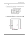

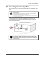

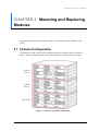
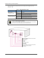
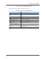
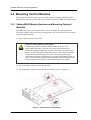
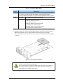
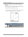
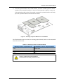
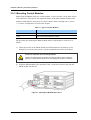
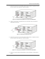
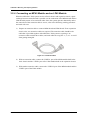
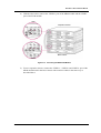
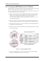
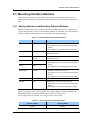
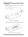
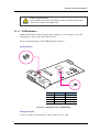
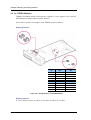
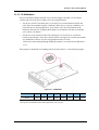
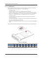
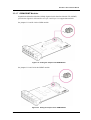
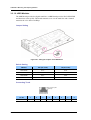
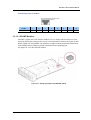
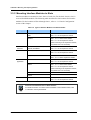
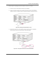
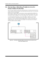
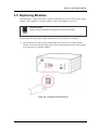
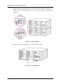
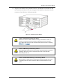

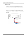
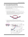
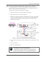
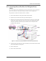

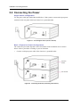
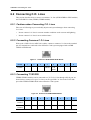
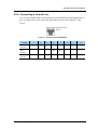

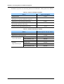
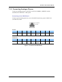
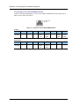
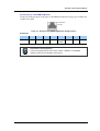
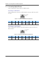

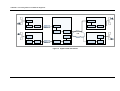
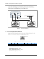
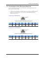
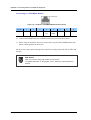
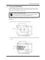
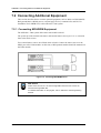
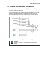
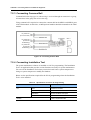
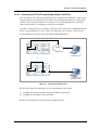
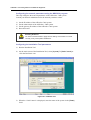
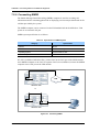
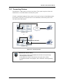


![SamsungProdBulletin_211_4_4x_Software_Release[1]](http://vs1.manualzilla.com/store/data/005825179_1-598976db56b1ef1012f4b9b7fb2b917f-150x150.png)