Download Sharp AR-FX2 Specifications
Transcript
AR-FX2 CODE: 00ZARFX2//A1E DIGITAL COPIER FAX EXPANSION KIT (For USA/Canada) AR-FX2 EXPANSION 2MB: AR-MM5 MEMORY 4MB: AR-MM6 MODEL 8MB: AR-MM7 CONTENTS [ 1 ] OUTLINE . . . . . . . . . . . . . . . . . . . . . . . . . . . 1 - 1 [ 2 ] SPECIFICATIONS . . . . . . . . . . . . . . . . . . . . . . 2 - 1 [ 3 ] INSTALLING PROCEDURE . . . . . . . . . . . . . . . . . 3 - 1 [ 4 ] ADJUSTMENTS . . . . . . . . . . . . . . . . . . . . . . . . 4 - 1 [ 5 ] SIMULATIONS . . . . . . . . . . . . . . . . . . . . . . . . 5 - 1 [ 6 ] SOFTWARE SWITCH DESCRIPTIONS . . . . . . . . . . . 6 - 1 [ 7 ] USER PROGRAMS . . . . . . . . . . . . . . . . . . . . . . 7 - 1 [ 8 ] PRINTING . . . . . . . . . . . . . . . . . . . . . . . . . . . 8 - 1 [ 9 ] FIRMWARE VERSION UP PROCEDURE . . . . . . . . . . 9 - 1 [10] TROUBLE CODE LIST . . . . . . . . . . . . . . . . . . . 10 - 1 Parts marked with “ ” are important for maintaining the safety of the set. Be sure to replace these parts with specified ones for maintaining the safety and performance of the set. SHARP CORPORATION This document has been published to be used for after sales service only. The contents are subject to change without notice. AR-FX2 [Copier mode] ● The START key indicator is lit. (Initial state.) [Fax mode] ● The display panel shows the following message (initial state): [Example] [1] OUTLINE A. Introduction This machine is the FAX expansion kit which is attached to the digital copier AR-160/200 series to provide facsimile functions. Note: 1) When attaching this machine, the SPF/RSPF, the LCD panel, and the motherboard are required. 2) The SPF (AR-SP2) or the RSPF (AR-RP1) must be installed to the copier which this machine is attached to . SEP 10 FRI 06:30 PM STAND-BY 100% ● The LINE STATUS indicator is not lit. SPF/RSPF (AR-SP2/AR-RP1) Job separator (AR-TR2) FAX expansion kit (AR-FX2) LCD panel kit (AR-PA1) Not lit FAX operation panel 2) Turn the power switch to the “OFF” position. ● If you turn the power off while the machine is in use, a misfeed may occur. Also, settings will be lost. Digital copier machine 2MB 4MB 8MB AR-MM5 AR-MM6 AR-MM7 Expansion memory (One of them is attached to.) B. Turning Power “ON” and “OFF” To turn the power on and off, use the power switch located on the left side of the cabinet. (1) Turning Power “ON” To use the fax or copier, turn the power switch located on the left side of the cabinet to the “ON” position. 1) Turn the power switch to the “ON” position. ● After 15 seconds, the system check is finished and the machine enters the copier or fax mode initial state. To switch between copier and fax modes press the COPY/FAX key. Power Off (3) Selecting Fax Mode This model has two modes: copier mode and fax mode. When the fax mode indicator above the COPY/FAX key is lit, you can use the machine as a fax. When the copier mode indicator is lit, you can use the machine as a copier. To change from copier mode to fax mode, press the COPY/FAX key. Features available with the fax function (for example automatic fax reception) are enabled even in copier mode. 1) If the copier mode indicator is lit, press the COPY/FAX key. ● The fax mode indicator lights up. ● If you are done faxing and want to enter the copier mode, press the COPY/FAX key again to select copier mode. Power On Note: ● When using the fax function, when the initial state is displayed, you can send faxes. ● When you turn on the power, the machine enters copier mode or fax mode depending on the last mode used before power was turned off. For example, if the machine is in copier mode and the power is turned off, it will enter copier mode when the power is turned on again. Likewise, if the machine is in fax mode and the power is turned off, it will enter fax mode when the power is turned on again. ● The machine is set up from the factory to enter a power save mode from the copier or fax modes if it is turned on and not used for a specified period of time. (2) Turning Power “OFF” You do not need to turn the power off unless you are trying to clear an alarm, removing foreign substances from within the machine, or moving the machine. Note: Do not turn of power while using the fax machine. If you turn off the power, you will not be able to receive faxes. 1) Confirm that the machine is idle. ● To confirm that the machine is idle, make sure one of the following conditions exists: Note: ● If the machine is in use, you cannot change modes. If you want to manually receive a fax or if you want to quickly enter fax mode, press the CLEAR key to interrupt copying, and press the COPY/FAX key. ● After sending or receiving faxes, the machine returns to the fax mode initial state, but does not return to the copier mode. 1 – 1 AR-FX2 a. Fax Mode Initial State In the fax mode initial state, the messages similar to the following are shown on the display panel. Depending on user program settings, this display may differ slightly from yours. Date Day SEP 10 FRI STAND-BY Time % in memory 06:30 PM 100% b. Fax Function Features Enabled in Copier Mode ● Automatic fax reception ● Timer operations ● Programs that use timer operations ● Relay request ● Sending documents in memory from memory sending mode 3 sec. (Super G3/33600bps) 6 sec. (G3 ECM/14400bps) Compression method MH, MR, MMR Modem speed 36600bps → 2400bps automatic fall back Compatibility Super G3/G3 Applicable telephone line Public switched telephone network (PSTN), Private branch exchange (PBX) Number of lines used 1 line (cannot be added) ECM YES OC YES(A3 to A5, 11 × 17 to 8.5 × 5.5) Transmission mode SPF/OC transmission changeover NO (changeover cannot be made at any time during document scanning) Document loading capacity, scanning cycle (SPF, RSPF) Automatic feed compatibility YES Document loading capacity 30 sheets Document scanning cycle 18 sheets/min. (Standard mode, A4R memory transmission/No rotate) Document scanning speed 3.3 sec./sheet (A4R: memory transmission, Standard mode/No rotate) Half tone (photo mode) 1. Communication System Transmission time YES(A3 to A5, 11 × 17 to 8.5 × 5.5) 3. Image processing system [2] SPECIFICATIONS Transmission method SPF Original size detection Contrast adjustment Contrast selection Resolution selection Standard 8 dots/mm × 3.85 lines/mm Fine 8 dots/mm × 7.7 lines/mm Super fine 8 dots/mm × 15.4 lines/mm Ultra Fine 16 dots/mm × 15.4 lines/mm: in compliance with ITU-T (Cannot be received when there is no extra memory, be received at Super Fine mode.) Print resolution Max. document width 297mm Unscannable region Leading edge: 5mm max. trailing edge: 6mm max., left end + right end: 6mm max. Transmitted document size Original size enter Printing size Print paper AB system: A3/B4/A4/A4R/A5 Inch system: 11 × 17/8.5 × 14/8.5 × 11/8.5 × 11R/ 5.5 × 8.5 AB system: A3/B4/A4/A4R/A5 Inch system: 11 × 17/8.5 × 14/8.5 × 11/8.5 × 11R/ 5.5 × 8.5 Duplex sending NO Long document YES(Max. 1000mm) Depends on document width and resolution. Auto/manual in 5 stages 600dpi (with resolution compensation) 4. Print system 2. Scanning system Original size Equivalent to 256 scales (At Fine/Super Fine/Ultra Fine mode) 2 – 1 Max. printing width 293mm (11 inch) Print paper size detection YES (All sizes) Printing size AB system: A3/B4/A4/A4R/A5 Inch system: 11 × 17/8.5 × 14/8.5 × 11/8.5 × 11R/ 5.5 × 8.5 Cassette capacity Standard: 250 sheet × 2 or 250 sheet × 1 Option : 250 sheet × 2 or 250 sheet × 1 Print paper empty detection YES Feed Tray All feed trays installed except Multi Bypass Tray Size setting Depends on size setting in the copy mode. AR-FX2 5. Transmission function Dialing function Dialing function F code Timer mode Recall mode Rapid key dialing 35 other parties Speed dialing 150 other parties Group dialing 35 groups (including the other parties registered to rapid key dialing) Search dial Any of other parties registered to speed dialing, rapid key dialing and group dialing can be searched for using the first three letters. Chain dialing YES Redialing The last number dialed is saved (dialing from ten-key pad only) Cannot be cleared by clear all key Program dial 5 programs Mode recall NO Sub address NO Password NO Timer mode: transmission/ polling Time of day specified for transmission or polling. Automatic recall mode when other party is busy Intervals 1 to 15 minutes Count 1 to 15 times/ 0: no re-transmission SEC/SECL:1 to 14 times/ 0:no retransmission Recall mode when communication error occurs Intervals 1 to 15 minutes/ 0: re-transmission immediately after line disconnection Count 0 or 1 times/ 0: no re-transmission USA Canada: 1 time/ 0: no retransmission Transmitted pages Direct transmission YES (SPF : 30 sheet, OC : 1 sheet) Default setting Setting made in user program Line sound monitoring function Dialing confirmation monitoring YES (Volume adjustment made/muting enable in soft SW) Broadcast function Broadcast Number of destinations 200 destinations (When group dialing is used, the number of other parties registered to group dialing is added) Transmission method Broadcast key, group key Usable numbers Numbers entered from the 10-key pad, all numbers registered to rapid key dialing Group dialing Transmitted to group dialing numbers registered to rapid keys Relay broadcast transmission Instructing station Only from the machine having Sharp relay broadcast instruction transmission function Relay station Only from the machine having Sharp relay broadcast transmission function Multiple relay NO Number of relay groups 10 groups Number of receiving stations that may be specified per group Up to 100 numbers in terms of rapid key dialing Other party’s station Only from the machine having Sharp confidential receiving function Beginning with the page where error occurred Number of transmissions counted in recall mode simultaneously Max. 50 transmissions Subsequent transmission reservation override in recall mode YES (ON/OFF in key operator program) Automatically reduced transmission Document is transmitted in reduced size according to other party’s machine YES (ON/OFF in key operator program) Memory transmission Memory transmission YES Number of transmission reservations that can be made 50 transmissions Processing when memory is full Transmission cancel or transmission of scanned data only Setting change after transmission setting NO Confidential transmission Scanning designation Page splitting NO Page coupling NO Variable scale factor NO Priority function Transmission reservation interrupt YES (By direct transmission) Broadcast interrupt YES (By direct transmission) Recall mode interrupt YES (Manual disabled) Serial transmission NO Serial transmission Rotational transmission 2 – 2 Paper size (Inch system) 8.5 × 11 → 8.511R Each can be set in user program. AR-FX2 Book document transmission Transmission method In OC mode Received data override output NO Consecutive page transmission (page splitting) NO Transfer Transfer at occurrence of trouble YES (by user program setting) Transfer method By the special transmission key in case of a trouble Numberspecified receiving Receiving of only specified number enabled NO Receiving of only specified number disabled NO Confidential function Confidential receiving Sender Only Sharp machine having confidential function Confidential box Up to 10 boxes may be set Confidential box name 20 letters Confidential ID code May be set per mailbox Verification stamp NO Memory Polling Memory Polling YES Polling Security Check by other party’s number YES Check by matching of system number (user’s own machine) and ID number (other party’s machine) (between Sharp machines only) YES 6. Receiving function system Receiving mode Default setting Automatic receiving Receiving mode Manual receiving Answering machine connection Automatic receiving (can be switched to manual receiving in Soft SW or Receive Mode key) Automatic receiving setting YES Number of calls 0 to 9 times (factory-set to twice: can be changed in user program) Automatic phone/ fax switching NO Non-call receiving Enabled by setting the number of calls to 0. Manual receiving setting YES Number of switching calls to automatic receiving in manual receiving mode NO Answering machine connection NO Receiving mode timer switching NO Variable scale factor receiving Reduction made within regular size YES (ON/OFF in user program) Reception data print size designation Available by tray designation By received data print size designation By selected paper feed tray (setting in user program), Memory receiving function Reduction Enlargement NO Substitute receiving into memory Only when data cannot be output Forced memory receiving Rotational receiving Split receiving According to cassette fitted Split size Long document, absence of receiving size paper Split receiving setting YES (according to paper selection condition in user program) Duplex receiving NO 2-in-1 receiving NO Polling Polling YES Resolution at Polling Fine Turn around transmission NO 7. Registration system Number registration NO 2 – 3 Speed dialing Number of other parties 150 other parties Number of other party’s number digits 40 digits Registered name 20 half-size letters (may be omitted) ∗ When omitted, register speed dialing number (000 to 149). Searched letters Up to 3 half-size letters User tag classification NO International communication mode setting YES AR-FX2 Number registration Speed dialing Transmission method Speed dialing keys + (000 to 149) + start key Rapid key dialing Number of other parties 35 other parties Number of other party’s number digits 40 digits Registered name 20 half-size letters (may be omitted) ∗ When omitted, register rapid key dialing number (01 to 35). Group dialing Number registration Program Searched letters Up to 3 half-size letters User tag classification NO International communication mode setting YES Transmission method Rapid key dialing Registration keys Rapid keys Max. number of registered other parties per group Registerable number Sender registration Polling/ Memory Polling security Letter input Sender’s name 40 half-size letters, registered in user program Sender’s number 20 digits, registered in user program Polling enable number Polling source number registration 10 numbers, 20 digits System number System number registration Up to 1 number, registered in user program ID number ID number registration Up to 10 numbers, registered in user program Input method Key input YES Letters that may be input Characters Alphanumeric characters, symbols Registered data read-out, read-in NO Date & time adjustment Registered in user program 100 other parties (total of registered other parties is up to 150) Date indication change YES (Order of year, month and day can be changed) Numbers registered to speed dialing and rapid key dialing, numbers entered from ten-key pad Backup SRAM used, builtin battery-backed Registered name 20 half-size letters (may be omitted) Searched letters Up to 3 half-size letters User tag classification NO Transmission method Group dialing Registered data backup at power failure 8. Telephone function system Handset NO On-hook Dial YES Hold NO Pause YES (1 to 15 seconds, set in user program) Phone transmission at power failure No (external phone transmission can be made) Ringer volume Adjusted in user program Speaker volume Adjusted in user program Number of programs 5 programs Tone pulse switching Registerable item All items that can be set for transmission Switched between 10 and TONE in user program External telephone YES 20 half-size letters (may be omitted) ∗ When omitted, register rapid key dialing number (1 to 35). Automatic telephone/fax switching Registered name Calling method By pressing the program key Setting change after calling NO 2 – 4 Remote receiving switching YES (switching number in 1 digit + + ) NO Audio response NO Response voice recording NO AR-FX2 9. Memory system Activity Report Memory Capacity Standard 2MB Option Up to 8MB (+2M/+4M/+8M) Confirmation Transmission reservation Display in LCD YES Print out YES Memory using condition YES (percent display) Memory Back-up YES (flash memory) Time-specified communication table Common to transmission record table Confidential receiving confirmation table YES Communication result table (transmission) YES (any of always output/only when transmission could not be made/not output is set in user program) Broadcast transmission report YES (any of always output/only destination to which transmission could not be made/not output is set in key operator program) Communication result table (receiving) YES (any of always output/only when transmission could not be made/not output is set in key operator program) Document image printing when memory transmission is not yet made YES (part of first page of document is printed: ON/OFF setting can be made in user program/confidential transmission data is never printed) Communica tion result table function Communication report table (Confidential reception) YES (Output/Not output) Other report/list Rapid key dialing list YES (output as telephone number list) Speed dialing list YES (output as telephone number list) Group dialing list YES Transmission message list NO ID/sender list YES Confidential ID list YES User switch list YES Memory image erasure table NO Communica tion result table function 10. Additional information function for transmission Page counter YES Date printing YES (Year/month/day, Year in 4 digits) Cover Sheet Transmission message Sender information Additional Date indication change YES Cover item Other party’s name YES Other party’s number YES Sender’s name YES Sender’s number YES Transmission message YES Print paper size A4, LETTER Regular message CONFIDENTIAL PLS. DISTRIBUTE URGENT PLS. CALL BACK IMPORTANT User message NO Sender’s number 20 digits Sender’s name 40 half-size letters 11. Additional printing function for receiving Index printing YES (setting in user program) 12. Listingfunction Activity Report List size A4, LETTER (not output if size setting is not A4, LETTER or larger) Activity Report memory capacity 50 communications for transmission/receiving respectively Number of communications 50 communications for transmission/receiving respectively Time-specified output YES(2times a day) When recording memory is full NO Printing sequence LAST IN LAST OUT Department-bydepartment output YES (department-bydepartment communication time is output as departmentby-department management record table) 13. Others CSI signal send out CSI signal send out YES Department management Department-by-department user restriction YES Number of set departments 20 departments Department-by-department charge management function NO LCD 20 letters by 2 lines Operation panel display 14. Items examined for addition 2 – 5 FAST For USA Distinctive Ringing For USA: 3 types For Canada: 5 types Auto Daylight saving setting For Europe USA time AR-FX2 2) Remove the operation panel. ● Remove the operation panel fixing screw, and remove the flat cable. [3] INSTALLING PROCEDURE 1. FAX expansion kit, LCD panel kit installation ● When installing the FAX expansion kit, the LCD panel kit is required. Parts included in the FAX expansion kit (1) FAX key unit (2) FAX PWB (5) FFC harness (6) FAX harness (9) M3 screws (gold color) (12) Label for note (3) TEL/LIU PWB (4) Speaker unit (7) Line harness (8) M3 screws (gold color) 3) Remove the ground wire. (Note: Depending on model or version, select the appropriate diagram (A or B) for ground wire removal.) (A) Remove the screw, and remove the ground wire. Then install the screw on the left side. (10) Harness securing tape (11) Supplied label (13) FCC Registration Label (14) FAX connector cover (1) (15) Operation manual (2) (16) Installation manual Packed items of the LCD panel kit LCD unit Installation fixture (B) Remove the screw, and remove the ground wire. Motherboard Ground plate M3 screws(gold color) M3 screws(silver color) Note: Before performing this procedure, be sure to disconnect the power plug from power outlet. If not, an electric shock may be resulted. 1) Remove the front cover of the copier machine. ● Open the bypass tray and the side cover. Remove the paper tray. Warp the front cover inside by pressing the both sides, and remove the front cover from the hinge arm of the machine. 4) Remove the cover. ● Remove the screw, and attach the LCD dummy cover and the FAX dummy cover. 5) Install the LCD unit. ● Attach the LCD unit from your side, engage the pawls with the attachment holes, and fix with screws. Then connect the flat connector. Blue line-must be up (1) (2) (3) M3X8 3 – 1 AR-FX2 10) Attach the front cover to the copier. ● Warp the front cover by pressing the both sides, and attach it to the hinge arm of the machine. After attaching the paper tray, close the side cover and the bypass tray. 6) Install the Fax key unit. ● Connect the flat cable to the machine connector and fold the flat cable under the FAX key unit. Fix the Fax key unit with screws. Blue line-must be up 7) Stick the supplied label. ● After removing the protective sheet from the operation panel, stick the supplied label to the left of the exposure indicators. 11) Remove the rear cabinet of the machine. ● Remove the document cover. Remove the screw and remove the rear cabinet. If an open/close detector is present, take care not to break the actuator. STANDARD FINE SUPER FINE ULTRA FINE HALF TONE AUOT MANUAL PHOTO 8) Attach the ground wire. ● Reattach the ground wire to the operation panel with the screw. Check that the ground wire is securely squeezed by the aluminum sheets. 12) Remove the shield plate of the copier. ● Remove the screw. 9) Attach the operation panel of the copier machine. ● Attach the flat cable and fix with a screw. Note: Before attaching the flat cable, release the connector lock and insert the cable. After attachment, lock the connector. 13) Attach the PWB mounting frame. ● If a ground plate is present, remove it and attach the PWB mounting frame by aligning the two positioning locators and using the supplied M3 screws (silver color) as shown in the illustration. Note: Check that the AC cord is passed under the projection (★) as shown in the figure. If not, loosen the AC cord holder screws, and pass it under the projection, then tighten two screws. Blue line-must be up M3 8 M3 8 M3 8 Ground plate Positioning locators 3 – 2 AR-FX2 14) Attach the FAX PWB. ● Fix it with (9) M3 screw (gold) packed together with the FAX expansion kit. 18) Attach the left cabinet to the copier. ● Attach the left cabinet using the screw, then pass the speaker harness through the hole of the PWB mounting frame and connect the speaker harness to the connector of the copier. M3x6 15) Attach the motherboard. (packed together with the LCD panel kit) ● As shown in the figure, tilt the part (electrolytic capacitor) on the MCU PWB, connect the connector from the machine, insert the connectors, and fix with M3 screw (gold). M3 x 8 for steel Speaker harness Caution Note: Take care so that the speaker harness does not become caught between the corner frame and the left cabinet. 19) Attach the TEL/LIU PWB. ● Attach the TEL/LIU PWB to the PWB mounting frame using the supplied M3 screws (gold color)(9), and then connect the TEL/LIU PWB and FAX PWB using the FFC harness. Note: Before attaching the FFC harness, release the connector lock and insert the cable. After attaching, lock the connector. 16) Remove the left cabinet from the copier. ● Remove the screw, remove the screw for securing the second and third mirrors, and then remove the left cabinet. Blue line(To the right) 17) Attach the speaker harness. ● Attach the speaker to the left side cabinet using the supplied M3 screws (gold color)(8), and then secure the speaker cable using the harness securing tape included in the FAX expansion kit. 20) Attach the shield plate. ● Attach with the screw. M3X6 Securing tape M3X6 3 – 3 AR-FX2 21) Attach the ground plate. ● Hang the hook, and fix with M3 screw (gold) packed together. 2. Expansion memory attachment (ARMM5, MM6, MM7) M3X6 1) Remove the FAX connector cover with a screwdriver. 2) Insert the memory card so that the model name is on the back. 3) Attach the FAX connector cover. (1) (3) (1) (2) (3) Power on position Power off position M3X6 22) Attach the rear cabinet of the machine. ● Cut off the notch section in the rear cabinet with nippers so that the cut surface is flat. Attach the FAX connector cover. Fix with the screw and attach the document cover. M3 x 8 for steel M3x6 FAX connector cover M4 x 10 for plastic M3 x 8 for steel 23) Time setup check ● Change the time setup referring to the SIM 26-22 24) Stick the label to the rear cabinet of the copier. ● Stick the FCC Registration Label to the position shown in the illustration. In order to manifest the compliance with FCC Part 68 and IC CS-03, it is required to provide the machine with the FCC Registration Number (USA), Ringer Equivalence (USA) and Ringer Equivalence (Canada). After installing the FAX expansion kit in the machine, please put the registration label, packed with the kit, on the prescribed location. After installing this kit to the product, stick the supplied FCC Registration Label to the specified location. FCC Registration Label Reference line 5mm 3 – 4 AR-FX2 [4] ADJUSTMENTS Section Adjustment items Density section A <FAX mode> SIM 46-12 B FAX mode density adjustment (Individual mode) <FAX mode> SIM 46-14 - 46-16 A Dial test <FAX mode> SIM 66-13 1 2 Communication section Adjustment procedures FAX mode density adjustment (Overall mode) B. FAX mode density adjustment (Individual mode) (<FAX mode> SIM 46-14 – 16) 1. Density section A. FAX mode density adjustment (Overall mode) (<FAX mode> SIM 46-12) 1) Set the test chart (TRAP23109SCZZ CCITT #3 chart) on the OC table as shown below, and close the OC cover. 1) Set the test chart (TRAP23109SCZZ <CCITT #3 chart>) on the OC table as shown below, and close the OC cover. A4 A4 A4 A4 Glass holding plate Glass holding plate 2) Switch to the FAX mode and execute SIM 46-14 to 46-16 depending on the adjustment mode. 3) After warming up, shading is performed and the current density level is displayed on the lower two digits of the display section. 4) Enter the set value with the 10-key to adjust the FAX image density. 5) Make a copy, and adjust the density with the copy as a reference. 2) Switch to the FAX mode and execute SIM 46-12. 3) After warming up, shading is performed and the current density level is displayed on the lower two digits of the display section in standard and auto density mode. 4) Enter the set value with the 10-key to adjust the FAX image density. 5) Make a copy, and adjust so that the following adjustment specification is satisfied. ∗ When an adjustment is made in this mode, the exposure level for each communication mode and each density mode are automatically adjusted accordingly. <Adjustment specifications> Resolution mode <Adjustment specifications> Density mode Auto Resolution mode Standard SIM FAX mode 46-12 CCITT #3 chart output result “3” is slightly copied. Set value The greater the set value is, the greater the density is, and vice versa. Set range Density changeover SIM Fine Switched with the density select key. FAX mode 46-14 Super fine Switched with the density select key. FAX mode 46-15 Ultra fine Switched with the density select key. FAX mode 46-16 1 – 99 4 – 1 Set value The greater the set value is, the greater the density is, and vice versa. Set range 1 – 99 AR-FX2 6) Start transmission from the line. 2. Communication section Note: These items are factory adjusted when shipping according to FCC standards. Therefore, do not change the setting in the market. H:xx L:yy 1:YES 2:NO SENDING DTMF A. Dial test (<FAX mode> SIM 66-13) (1) Dial pulse transmission test 1) Execute SIM 66-13 in FAX mode. 2) Execute the dial pulse mode according to the instructions on the LCD display. xx: High group soft SW set value yy: Low group soft SW set value SIM SELECT SIGNAL 1:PULSE 2:DTMF DTMF transmission level 3) Set the make time. INPUT MAKE TIME (0–15) 4) Select the dial to be transmitted. Default: 0123456789# (After deleting with the clear key, it can be set to any desired value.) 5) Transmission is started from the line. SEND yyPPS xxm s 1:YES 2:NO SENDING yyPPS xxm s SIM Dial pulse make time 10 PPS FAX mode 66-13 Soft SW Initial value SW671 – 4 40ms (14) Set value SW set value: 0 – 15 Make time: 25 – 41ms 1ms step (Binary input) (2) DTMF signal transmission level adjustment 1) Execute SIM 66-13 in the FAX mode. 2) Execute the DTMF mode according to the instructions on the LCD display. SELECT SIGNAL 1:PULSE 2:DTMF 3) Select the signal transmission level. The signal transmission level is classified into two groups: the high group, and the low group. Transmission can be made with either of default and the soft SW set value. SELECT HIGH LEVEL 1:DEFAULT 2:SOFT SW. SELECT LOW LEVEL 1:DEFAULT 2:SOFT SW. 4) The transmission level can be set when the following menu is displayed on the LCD. (et value 1 = 0.5dB change) INPUT VALUE (0–15) (This value is returned to the original value when the simulation mode is canceled.) 5) Select the dial signal to be transmitted. Default: 0123456789# (After deleting with the clear key, it can be set to any desired value.) 4 – 2 High (FAX group mode) 66-13 Low group (Test only) Soft SW Initial value SW531 – 4 3.5dB (7) SW535 – 8 3.5dB (7) Set value SW set value: 0 – 15 Transmission level: 0 – 7.5db 0.5ms step (Binary input) AR-FX2 [5] SIMULATIONS B. FAX mode 1. Entering the simulation mode A. Copy mode The following key operations allow to enter the simulation mode from the copy mode. Clear key → Interruption key → “0” key → Interruption key → Main code → Start key → Sub code → Start key Main code Sub code 22 11 Fax related counter display 14 Fax ROM ver. Display 24 14 FAX related counter clear 46 12 FAX mode density adjustment (AUTO) 14 FAX mode density adjustment for each resolution (Fine) 15 FAX mode density adjustment for each resolution (Super Fine) 16 FAX mode density adjustment for each resolution (Ultra Fine) 02 User switch front print 03 Soft switch setting table print B. FAX mode The following key operations allow to enter the simulation mode from the FAX mode. Clear key → Interruption key → “0” key → Interruption key → Main code → Start key → Sub code → Start key Or perform the following key operations: “9” key → “ ” key → “8” key → “#” key → “7” key 2. Cancel of simulation mode Press the clear all key to cancel the simulation mode. Press the interruption key to interrupt the operation and return the sub code entry menu. 64 3. Simulation list 66 A. Copy mode <Related to the FAX kit> Main code Sub code 22 20 FAX print counter display 24 11 FAX print counter clear 13 Scan counter clear 26 1 Option switch display 48 1 Main scanning (Front/Rear) direction magnification ratio adjustment (Common in copy, FAX/OC, SPF) 6 OC mode sub scanning direction magnification ratio adjustment in FAX mode 7 SPF mode sub scanning direction magnification ratio adjustment in FAX mode 04 Dump list print 01 FAX related soft SW setup check/change 02 FAX related soft SW clear (Excluding adjustment values) 03 FAX PWB memory check 04 Signal send mode 06 Confidential communication password print 07 Image memory contents output 08 Voice message clear 10 Image memory clear 11 300bps signal send 13 Dial test 17 DTMF signal send mode 22 Handset sound volume adjustment 30 TEL/LIU status change check 32 Received data check 34 Communication time measurement/check 37 Speaker sound volume adjustment 38 Time setup/check Content ∗ This Service Manual describes only the items related to the FAX kit. For the other items, refer to the Service Manual of the main machine. ∗ Content A A ∗ A: Not used 4. Details of simulations A. Copy mode Main code Sub code 22 20 24 Content FAX print counter display Operational description Used to display the current Fax print counter value. ∗1 11 FAX print counter clear Used to clear the Fax printer counter. ∗2 13 Scan counter clear Used to clear the scan counter. ∗2 ∗1: Counter display method To display 12345: “123” (0.75sec) → Blank (0.3sec) → “456” (0.7sec) → Blank (1.0sec) → Repeat ∗2: Display after clearing each counter “000” (0.7sec) → Blank (0.3sec) → “000” (0.7sec) → Blank (1.0sec) → Repeat 5 – 1 Initial value Set range AR-FX2 Main code Sub code 26 1 Content Option switch display Operational description 1 6 7 Set range Used to display the installed options with LED on the operation panel. Key operation Display switch: magnification ratio key 48 Initial value Display <LED lighted when installing an option> • When “A” is displayed on the display: Shifter: Paper empty LED Job separator : JAM LED SPF: SPF select LED RSPF: SPF JAM LED Dehumidifier heater: Main body JAM LED Duplex mode: Main cassette select LED Simplex mode: Multi manual feed select LED • When “b” is displayed on the display: Cassette (2-stage): No. 2 cassette select LED Cassette (3-stage): No. 3 cassette select LED Cassette (4-stage): No. 4 cassette select LED Memory installation: Paper empty LED FAX: JAM LED Printer: Main body JAM LED ERDH: Main cassette select LED 16CPM: SPF JAM LED 20CPM: SPF select LED Document sensor: Auto paper select LED Main scanning (front/rear) direction magnification ratio adjustment (Common in copy, FAX/OC. SPF) After warming up, shading is performed and the main scanning (front/rear) direction magnification ratio and OC mode document off-center are adjusted. OC mode sub scanning direction magnification ratio adjustment in FAX mode After warming up, shading is performed and the OC mode sub scanning direction magnification ratio in FAX is adjusted. SPF mode sub scanning direction magnification ratio adjustment in FAX mode After warming up, shading is performed and the SPF mode sub scanning direction magnification ratio in FAX is adjusted. Key operation Adjustment mode select: Magnification ratio display key Manual main scanning direction magnification ratio adjustment set value: Copy quantity set key 1 – 99 Display Auto magnification ratio adjustment: Auto LED Manual magnification ratio adjustment: Manual LED OC mode document off-center adjustment: Photo LED 1 – 99 Key operation FAX OC mode sub scanning direction magnification ratio: Copy quantity set key Key operation FAX SPF mode sub scanning direction magnification ratio: Copy quantity set key 5 – 2 1 – 99 AR-FX2 B. FAX mode Main code Sub code 22 11 FAX related counter display The current Fax related counters are displayed on the LCD. Display Copy quantity Transmission counter Reception counter Time Accumulated transmission time Accumulated reception time 14 FAX ROM Ver. Display The currently installed ROM version is displayed on the LCD. Content Operational description Display FAX ROM: FAX PWB ROM version CPU: FAX PWB CPU version 24 14 FAX related counter clear The current FAX related counters are cleared. • Transmission counter (Time, number of sheets) • Reception counter (Time, number of sheets) 46 12 FAX mode density adjustment (Overall mode) After warming up, shading is performed and the currently set density level (Fine mode, auto exposure) is displayed. For the adjustment procedures, refer to the previous descriptions. 14 FAX mode density adjustment for each resolution (Fine) After warming up, shading is performed and the currently set density level (Fine mode) is displayed. For the adjustment procedures, refer to the previous descriptions. 15 FAX mode density adjustment for each resolution (Super fine) After warming up, shading is performed and the currently set density level (Super fine mode) is displayed. For the adjustment procedures, refer to the previous descriptions. 16 FAX mode density adjustment for each resolution (Ultra fine) After warming up, shading is performed and the currently set density level (Ultra fine mode) is displayed. For the adjustment procedures, refer to the previous descriptions. 02 User switch table print Used to print the currently set user switch table. 03 Soft switch setup table print Used to print the currently set soft switch. (FAX send counter, communication time, option status, ROM version) 04 Dump list print Used to print the SRAM contents as a dump list in blocks of 0 – 127. Select block 0 – 127 and press the START key to start printing. 01 FAX related soft SW setup check/change Used to check and change the current soft switch setup. 02 FAX related soft SW clear (Excluding the adjustment values) Used to set the following soft SW to the default. <Line signal adjustment value> • Signal send level (SW5-5 – 8) • DTMF send level (High group) (SW53-1 – 4) • DTMF send level (Low group)(SW53-5 – 8) • Make time (10PPS) (SW67-1 – 4) 03 FAX PWB memory check Used to check each memory installed on the FAX PWB. 64 66 Key operation <Memory> 1: DRAM 2: SRAM 3: FLASH 4: OPTION 5: PAGE Display <Error status> SUM NG: Check sum error A-BUS NG: Address bus error DATA NG: Data check error D-BUS NG: Data bus error ERASE NG: Data erase error 5 – 3 Initial value Set range AR-FX2 66 ● The following signals are sent to the line and the main body speaker. 04 <Signal send level> 0db: Signals are sent in 0db. Soft SW: Signals are sent in the level set with the soft SW. Display/Key operation <Send signals> 01: No signal (CMLON) 02: 33600bps (V34) 03: 31200bps (V34) 04: 28800bps (V34) 05: 26400bps (V34) 06: 24000bps (V34) 07: 21600bps (V34) 08: 19200bps (V34) 09: 16800bps (V34) 10: 14400bps (V34) 11: 12000bps (V34) 12: 9600bps (V34) 13: 7200bps (V34) 14: 4800bps (V34) 15: 2400bps (V33) 16: 14400bos (V33) 17: 12000bps (V33) 18: 19: 20: 21: 22: 23: 24: 25: 26: 27: 28: 29: 30: 31: 32: 33: 34: 35: 14400bps (V17) 12000bps (V17) 9600bps (V17) 7200bps (V17) 9600bps (V29) 7200bps (V29) 4800bps (V27ter) 2400bps (V27ter) 300bps (FLAG) 2100Hz (CED) 1100Hz (CNG) 300bps (V21) 2100Hz (ANSam) Pseudo ring sound Voice message silent Ring back tone silent Dial pulse make Dial pulse break ● The send signals are as follows: 01: No signal is sent. 26: 7eH flag signal 27, 28, 30: Tone signal 31: Pseudo ringer sound (With the On-hook key pressed) 32: Voice message silent <Not used> 33: Ring back tone silent <Not used> 34: Dial pulse make Under the state where dial pulses can be sent to the line, the make state is kept. 35: Dial pulse break Under the state where dial pulses can be sent to the line, the break state is kept. Other than the above: FFH ● The signal send level is selectable between 0db or the soft SW set value. Since, however this setup is not required for pseudo ringer sound, voice message (silent), ring back tone (silent), and dial pulse make/break., the selection menu does not appear. (For 01, 31 to 35, selection between 0db and the soft SW set value cannot be made.) ● Signal send is continued until an interruption command is outputted. ● The signal send level is returned to the soft SW set value before execution of this mode when this mode is terminated. 06 Confidential communication password print Used to print the currently set confidential communication password. 07 Image memory content output Used to print all image data stored in the image memory. The following image data are also outputted. ● Image data received in a confidential communication remote send image data read in the memory Note: Image data are cleared after being outputted. 08 Voice message send <Not used> 10 Image memory clear Used to send the voice reply message. <Sound volume setup> LARGE: Signals are sent in the LARGE sound volume level. Soft SW: Signals are sent in the level set with the soft switch 70-1. <Message> 1: “Wait for a moment.” 2: “No one is around the phone. For FAX send, please press the START button. (FAX/TEL reply message) 3: Reserved sound Used to clear all data stored in the image memory. The following data are also cleared. • Image data received in confidential communication • The management table is also initialized. 5 – 4 AR-FX2 66 11 300bps signal send Used to send signals in 300bps. Display/Key operation <Signal send level> <Signal pattern> 0db: Signals are sent in 0db. 1: No signal Soft SW: Signals are sent in the 2: 111111 level set with the soft switch. 3: 111110 4: 000000 5: 010101 6: 000001 13 Dial test Used to check dial pulses (10PPS), check the DTMF signal send, adjust the dial pulse make time, and adjust the DTMF signal send level. For adjustment procedures, refer to the previous descriptions. <Signals> Dial pulse (10PPS) DTMF signal 17 DTMF signal send Used to send the DTMF signal. When another dial number is pressed during DTMF signal send, the DTMF signal corresponding to the pressed dial number is sent. Display/Key operation <Signal send level> <Send dial number> 0db: Signals are sent in 0db. 10-key Soft SW: Signals are sent in the level set with the soft switch. 22 Handset sound volume adjustment <Not used> 30 TEL/LIU status change check Used to set the handset sound volume. Key operation 1: Small 2: Large Used to display the following status change of TEL/LIU. • Polarity reverse relay • External telephone hook switch relay Display LOW Signal HS1 HS2 EXHS ON ON ON HIGH OFF OFF OFF 32 Reception data check Used to check the fixed data received from the line. Since a nit to send the fixed data is required, this mode is not required in this market. 34 Communication time measurement display Used to make transmission and reception tests, measure the time required for transmission (reception) of image data in the communication, and inform of it. • Measurement range Transmission: From sending of the flag signal before sending of the image data to sending of RCP frame. Reception: From reception of the flag signal before reception of the image data to reception of RCP frame. The communication test is performed in the standard display. After completion of communication, the time measured in this mode is checked. • The setup items in transmission are as follows: • Communication means: memory transmission • Image quality: Standard • Density: Light ECM: ON Transmitter record: OFF 37 Speaker sound volume adjustment Used to set the speaker sound volume. Key operation 0: 1: 2: 3: 38 Time setup/check No sound Small Medium Large Used to display and correct the time (year, month, day, day of week, hour, minute) installed in the FAX PWB. 5 – 5 AR-FX2 [6] SOFTWARE SWITCH DESCRIPTIONS 1. Software switch changing procedure 2. Details 1) Execute SIM 66-01 in the FAX mode. 2) Select “1.YES” in the FAX soft SW setup. 3) FAX soft SW No. input XX (2 digits: 10-keyinput) + START key 4) Select “1.YES” in the Soft SW content check. 5) Press the bit No. to be changed, and the bit No. is highlighted. 6) Select “1.YES” in the confirmation menu of change. 7) The change is completed, and the display returns to the soft SW select menu. SW NO. Data NO. SW1 1 2 Item Image quality priority selection Switch selection and contents of functions Used to select the image quality setup (LED) among “Ultra fine”, “Super fine”, “Fine”, and “Standard” after pressing C/A key or in auto clear procedure SW1 Bit No. Standard Fine Super fine Ultra fine 3 Reserved 4 Auto/manual default setup Send request protection Reduction send mode Sent document print in memory send error 0 151 0 Auto reception 0 Manual can be set only when an external telephone is connected. Protected 0 118 Reduction 0 124 Print 0 138 0: Auto reception 0: Protected Used to set whether the transmitted document is received in reduction size or both ends of recording paper are cut when the transmitted document width is greater than the recording paper width. 0: Reduction Used to set Print/Not print part of the sent document in the transmission result table in case of a memory transmission error. For confidential transmission, however, no output is made. 1: Not print 8 Standard Remark 2 0 1 0 1 Used to set enable/disable of the confidential function (inhibition against erroneous transmission) during send request communication (remote transmission).The confidential function is performed with identification of the code numbers which is registered in the machine and the other party machine. Sender No. ← → Send request allow No. or system No. ← → ID No. 1: Standard 7 User program No. Initial value 0 1: Not protected 6 1 0 0 1 1 Used to select Auto/Manual reception mode when turning on the power. (When no external telephone is connected, do not select Manual. However, setup is possible and reception can be made by on-hook. 1: Manual reception 5 When a value which is outside of the specified range is entered, the item is automatically set to the default. Never change the switches which are “Reserved”. 0: Print Reserved 0 6 – 1 AR-FX2 User program No. SW NO. Data NO. SW2 1 Reserved 0 2 Reserved 0 3 Reserved 0 4 Reserved 5 Remote select No. setup 6 Item 7 8 Switch selection and contents of functions 1 2 Density default setup 3 5 6 Reserved 7 Size specification 8 Used to set the density (LED) after pressing C/A key or in auto clear operation to Auto, Light, Slightly light, Medium, Slightly data, and Dark. 1 0 1 0 0 0 0 2 3 Recall interval in case of a communication error 4 Set value 5 7 8 Recall interval in case of busy state 3 0 0 0 1 0 0 4 0 0 0 0 1 0 108 1 0 When a value in the range of 10 – 15 is set, set to “5.” 1 Auto 153 0 0 5 0 0 0 0 0 1 7 8 1 0 0 1 1 1 If the machine information is uncertain when set to “Follows the machine information”, the metric size is effective. Used to set recall interval after disconnection of communication due to a communication error in memory transmission. The set range is 0 to 15 min in the increment of 1 min by binary input. When set to 0, recall is made immediately after disconnection. However, the time interval set by SW21 (Interval between the end of a communication and the next call) is taken. SW4 Bit No. 6 0 0 0 0 Follows the machine information. 1 2 0 0 1 0 0 0 Used to set the source of judgement of size specification (AB series or inch series). SW Bit No. Inch size Follows the machine information. SW4 5 1 2 3 4 5 6 7 8 0 – 9 (Binary input) SW Bit No. Auto Light Slightly light Medium Slightly dark Dark 4 Remark 0 Used to set the number for remote select reception from an external telephone with binary input. However, the remote select numbers “x∗” and “∗” are fixed. For an input over “10”, the same operation as the initial value of “5” is performed. SW2 Bit No. Set range SW3 Initial value 1 2 3 4 0 – 15 (Binary input) 5 6 7 8 0 – 15 (Binary input) 6 – 2 1 min ∗ 1 0 113 0 0 1 0: Immediate recall after disconnection. Used to set recall interval after disconnection of communication due to the busy state of the other party or no response. The set range is 0 to 15 min in the increment of 1 min by binary input. When set to 0, recall is made after 3 min. SW4 Bit No. Set value Follows the machine information. 3 min 0 0 1 1 111 When “0000” is tried to be set, “0011” is set. AR-FX2 User program No. SW NO. Data NO. SW5 1 Reserved 0 2 Reserved 0 3 Reserved 0 4 Reserved 5 Signal send level 6 Item 7 8 SW6 1 Switch selection and contents of functions ANSam (CED) signal send 3 CSI send 4 DIS reception check in G3 send 5 6 Used to set whether non-modulation carriers are sent or not in V.29 transmission. EOL detection timer Used to set the detection timer of EOL (End Of Line) in phase C reception. 1: 25 sec 7 8 0: Once when receiving NSF, twice when receiving DIS Nonemodulation carrier in V.29 send 1: YES YES 1 Setup in communication other than V.34 YES 1 Effective only when V.34 mode function are disable. YES 1 Once when receiving NSF, twice when receiving DIS 0 NO 0 13 sec 0 75 ms 0 200 ms 0 0: 13 sec Used to set the time interval from CED sending to FSK signal sending of DIS. Countermeasure for echo in transmission Used to set the time interval from DIS reception to DCS signal sending. 1: 500 ms 1 0: NO Countermeasure for echo in reception (CED toner send interval) 1: 500 ms 1 0: NO Used to set whether DIS reception is checked or not in G3 mode. 1: Twice 1 0: NO Used to set whether CSI signal send is perform or not. The CSI signal includes the transmitter No. 1: YES 0 0: NO Used to set whether ANSam (CED) signal send is made or not. This is effective only when SW52-7 (V.34 mode function) is OFF. This is because ANSam signal send is indispensable in V.34 mode. (This machine uses the ANSam signal also as the CED signal.) 1: YES 7 (–12 dBm) 5 6 7 8 0 – 15 (Binary input) Used to set whether ECM (Error Correction Mode) is performed or not. When, however, SW52-7 (V.34 mode function) is set to OFF, or when SW52-7(V.34 mode function is set to ON and the transmission is not the super G3 transmission, ECM Disable setup is effective. This is because the ECM function is indispensable in a transmission other than super G3 transmission in V.34 mode and the other party machine may perform checking. With SW52-7 (V.34 mode function) is ON and this reception function is disabled. 1: YES 2 Remark 0 Used to set the signal send level from the Modem. The set range is 0 – 15 in the increment of 1dBm by binary input. The value becomes – (Set value) – 5 dBm to the actual in theory. SW5 Bit No. Set value ECM Initial value 0: 75 ms 0: 200 ms 6 – 3 If either of SW67 or SW6-8 is effective, open of the line after completion of communication is delayed by 1.5 sec. 
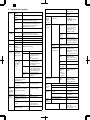
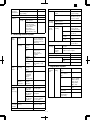
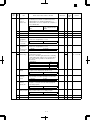
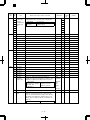
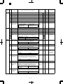
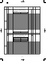
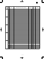
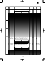
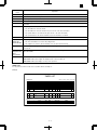
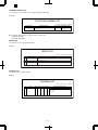
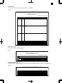
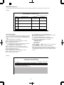
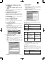
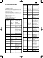
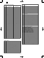
AR-FX2 SW NO. Data NO. SW7 1 Item MH fixing Switch selection and contents of functions Used to fix the image data compression method in transmission to MH. However, when SW52-7 (V.34 mode function) is OFF or when SW52-7 (V.34 mode function) is ON in transmission, MH fixing is effective. This is because MMR function is indispensable in V.34 mode and the other party machine may perform checking. When SW52-7 (V.34 mode function) is ON in reception, this function is disabled. 1: YES 2 Reserved 3 Busy tone detection Used to set whether the busy tone signal is detected or not in calling or pseudo calling of external telephone. 5 Reserved 6 Max. length of reception Used to set the max. length of reception. Modem speed fixing in reception Used to set the start speed of reception procedure when receiving from an other party other than V.34. Reception procedure is made in the set speed. YES 1 0 0 1. No limit 1.5 m 0 Max. length 1m in transmission is monitored with MCU. No fixing 0 Setup in a communication other than V.34 0: 1.5m 7 0 0 1 1 0 8 0 1 0 1 1 Used to set whether the transmission mode is memory Memory transmission/Dire transmission or direct transmission after pressing C/A key or in auto clear operation. ct transmission default setup 1. direct transmission 0: Memory transmission Memory transmissio n 0 2 Memory reception YES 1 When set to 0, reception is not made in auto reception under the following state: Cover open, unit error (toner, drum, developing section error), paper exit tray full, recording paper jam, document jam, no print paper. When set to 1, memory reception is enabled. 1. YES 3 Reserved 4 Reserved 5 Remote reception direction Setup in a communication other than V.34 2: NO Reserved SW7 Bit No. No fixing V.29 – 9600 bps V.27ter – 4800 bps V.17 – 14400 bps SW8 0 0 4 8 NO Remark 2: NO (Depends on the other party machine.) 1: YES 7 User program No. Initial value 0: NO 0 0 Used to set whether remote select function is used or not. 1. YES YES 1 0: NO 6 Reserved 0 7 Reserved 0 8 Reserved 0 6 – 4 152 AR-FX2 SW NO. Data NO. SW9 1 SW10 Item Communication record total time/total number of sheets print Switch selection and contents of functions Used to set whether total communication time and total number of sheets are recorded or not on the communication record table. 1. YES 1 2 Reserved 0 3 Reserved 0 4 Reserved 0 5 Reserved 0 6 Reserved 0 7 Reserved 0 8 Reserved 0 1 Communication time count (Image) 2 SW12 YES Transmitter TEL number registration Used to measure the communication time in phase C. However, it is the communication time in the latest phase C. (Unit: msec) YES 1 Enable 0 0: NO Used to set Enable/Disable of registered transmitter telephone number change. 1: Disable 0: Enable 3 Reserved 0 4 Reserved 0 5 Reserved 0 6 Reserved 0 7 Reserved 1 8 Reserved 0 1 Reserved 1 2 Reserved 0 3 Reserved 0 4 Reserved 0 5 Reserved 0 6 Reserved 0 7 Reserved 0 8 Reserved 0 1 Reserved 0 2 Reserved 0 3 Reserved 0 4 Reserved 0 5 Reserved 6 CI detection 7 0 Used to set the frequency to detect CI signal which is the calling signal as follows: SW12 Bit No. 4 Sine wave 3 Sine wave 2 Sine wave 8 Remark 0: NO 1. YES SW11 User program No. Initial value 6 0 1 0 4 Sine wave 0 0 7 0 0 1 Reserved 0 6 – 5 When set to “11”, set to “00”. AR-FX2 SW NO. SW13 Data NO. Item Switch selection and contents of functions 1 Reserved 0 2 Reserved 0 3 Call ring sound volume 4 Used to set the reception sound volume regardless of handset. SW13 Bit No. Silent Small Medium Large 3 0 0 1 1 Medium 1 Reserved 1 Reserved 0 7 Interface data output Interface broadcasting function Used to set whether the received document is outputted from the interface direction station when interface broadcasting direction is received. 1 V.34 mode transmission speed 3 Used to set whether interface broadcasting transmission is performed when receiving the interface broadcasting direction from the other party or the interface broadcasting direction is not received from the other party. When this function is set to 0 (Inhibited), the interface broadcasting direction can be transmitted. 4 5 6 7 8 V.34 mode reception speed Enable 1 Interface direction reception setup 1 When set to 2400 bps, SW58 No. 1 – 6 must be set accordingly. 1 0 0 0 0 0 0 0 0 2 0 0 0 0 1 1 1 1 3 0 0 1 1 0 0 1 1 4 0 1 0 1 0 1 0 1 SW14 19200 21600 24000 26400 28800 31200 33600 33600 Bit No. bps bps bps bps bps bps bps bps 1 1 1 1 1 1 1 1 1 2 0 0 0 0 1 1 1 1 3 0 0 1 1 0 0 1 1 33600 bps 1 5 0 0 0 0 0 0 0 0 6 0 0 0 0 1 1 1 1 7 0 0 1 1 0 0 1 1 8 0 1 0 1 0 1 0 1 SW14 19200 21600 24000 26400 28800 31200 33600 33600 Bit No. bps bps bps bps bps bps bps bps 6 – 6 5 1 1 1 1 1 1 1 1 6 0 0 0 0 1 1 1 1 7 0 0 1 1 0 0 1 1 1 4 0 1 0 1 0 1 0 1 Used to set the reception speed when starting reception in V.34 mode. When set to 2400 bps, SW58 No. 1 – 6 must be changed to 2400 only. SW14 Bit No. 2400 bps 2400 bps 4800 bps 7200 bps 9600 bps 12000 bps 14400 bps 16800 bps 1 0: Disable Used to set the transmission speed when starting communication in V.34 mode. When set to 2400 bps, SW58 No. 1 – 6 must be changed to 2400 only. SW14 Bit No. 2400 bps 2400 bps 4800 bps 7200 bps 9600 bps 12000 bps 14400 bps 16800 bps YES 0: NO 1: Enable 2 104 0 6 8 Remark 4 0 1 0 1 5 1: YES SW14 User program No. Initial value 8 0 1 0 1 0 1 0 1 0 33600 bps 1 1 1 0 When set to 2400 bps, SW58 No. 1 – 6 must be set accordingly. AR-FX2 SW NO. Data NO. SW15 1 2 Item Used to set the lower limit of busy tone detection time (ON time). Upper limit of busy tone detection time Used to set the upper limit of busy tone detection time (ON time). Reserved 4 Reserved 5 Modem speed (other than V.33 mode) 7 SW17 1 Reserved 2 External telephone connection 0 750 ms 0 0: 750 ms 0 0 Used to set the communication start speed other in a mode other than V.34 mode. In areas of poor communication conditions, this setup is used to reduce the communication speed in advance. 5 0 0 0 0 0 0 0 0 6 0 0 0 0 1 1 1 1 7 0 0 1 1 0 0 1 1 8 0 1 0 1 0 1 0 1 SW15 Bit No. V.17 14.4 kbps V.17 9600 bps V.17 12.0 kbps V.17 7200 bps ★ ★ ★ ★ 5 1 1 1 1 1 1 1 1 6 0 0 0 0 1 1 1 1 7 0 0 1 1 0 0 1 1 V.17 14.4 kbps 1 For the bits marked with ∗, set to V.17 14.4 kbps. 0 0 8 0 1 0 1 0 1 0 1 0 0 Used to set whether an external telephone is connected or not. 1: YES YES 1 Reserved 0 4 Reserved 0 5 Reserved 0 6 Rotation transmission select (8.5″ × 11″ → 8.5″ × 11″R) Used to set whether 8.5″ × 11″ document is sent as 11″ × 17″ width (8.5″ × 11″) or it is sent as 8.5″ × 11″R by rotating read images. 1: YES 106 0: NO 3 YES 1 125 0: NO 7 Reserved 0 8 Reserved 0 1 Reserved 2 Output conditions setup 3 0 Used to set the size of paper to output when a document is received. SW17 Bit No. ABD ABC A: B: C: D: SW17 250 ms Remark 0: 250 ms 1: 650 ms SW15 Bit No. V.27 2400 bps V.29 9600 bps V.27 4800 bps V.29 7200 bps V.33 14.4 kbps ★ V.33 12.0 kbps ★ 8 SW16 1: 350 ms User program No. Initial value Lower limit of busy tone detection time 3 6 Switch selection and contents of functions ABD 0 0 2 3 0 0 1 0 Optimum size output (Received size) Larger than the optimum Divided output Reduced output 4 Reserved 0 5 Reserved 0 6 Reserved 0 7 Reserved 0 8 Reserved 0 6 – 7 133 When set to “11” or “01”, set to “00” (ABD). AR-FX2 SW NO. SW18 Data NO. Item Switch selection and contents of functions User program No. Initial value 1 Reserved 0 2 Reserved 0 3 Reception size specification (Shows reception capacity.) Used to set the receivable document width which is informed the other party when receiving a communication. The setup items are as follows: 11″ reception capacity setup Used to set the recording width of DIS signal when the set paper size is Ledger (11 × 17, main scanning 279.4mm, sub scanning 4318mm), Letter R (8.5 × 11R, main scanning 215.9mm, sub scanning 279.4mm), Letter (8.5 × 11, main scanning 279.4mm, sub scanning 215.9mm) or Legal (8.5 × 14, main scanning 215.4mm, sub scanning 355.6mm). 4 5 SW18 Bit No. By the installed cassette 215 mm 255 mm (215 & 255 mm) 303 mm (215 & 255 & 303 mm) 1: 255/215 mm 3 0 1 0 1 By the installed cassette 0 303/255/ 215 mm 0 11″ width print 0 Remark ∗1: Refer to the following descriptions. 0 4 0 0 1 1 ∗2 Refer to the following descriptions. 0: 303/255/215 mm For each setup, be careful of the following items. <255mm and 215mm> When the other party sends documents of 11″ width or A3 width, the size is automatically reduced to 255mm in the other party’s machine. <303mm, 255mm, and 215mm> When the other party sends documents of 303mm width, and when reception is made on Ledger, Letter, or Letter R (rotation print) paper, the data over the paper size are cut out. (When printed on Legal paper in rotation printing, the data are not cut.) In this case, if the other party’s machine is of inch spec and sends documents of 11″ width, there is no problem. If the other party’s machine is of AB spec and sends document of A3 width, data are cut. 6 SW19 Output method in A3 width reception 7 Reserved 8 Reserved 1 Protocol monitor Used to set the output method when A3 width data are sent from the other party’s machine. 1: Data of A3 width is printed. Send reservation interruption enable in recall mode 0: Data of 11″ width is printed. 0 0 Used to set whether the protocol monitor of one communication is printed or not. 1: YES 2 126 0 Enable 1 0: NO Used to set whether send reservation interruption is allowed or not in standby for recall. 1: Enable NO 115 0: Disable ∗1: When “By the installed cassette” is selected, the max. recording size on the tray which is set to ON in the recording paper tray selection (SW27-2 – 5) becomes effective. When all of the recording paper tray selection (SW27-2 – 5) are set to OFF, the reception of A3 (A4, B4, A3) is allowed. (The soft SW is not changed.) ∗2: When 11″ paper which allows reception of FAX is set, setting of this SW informs of the reception capability. If the setting of SW18-3 to -4 (Reception size designation) is set to “By the installed cassette”, this setting has the priority. 6 – 8 AR-FX2 SW NO. Data NO. SW19 3 Item Output only in case of protocol monitor error Switch selection and contents of functions Effective only when SW19-1 is set to 1 (YES). Used to set whether protocol monitor is outputted only when a communication is not completed normally due to a communication error or it is outputted after completion of every communication. 1: Only in case of an error NO 0: After completion of every communication (All output) Reserved 0 5 Reserved 0 6 Reserved 7 Time designation 1 of communication record table Used to set whether the communication record table is printed at the designated time 1 or not. Time designation 2 of communication record table Used to set whether the communication record table is printed at the designated time 2 or not. Line sound monitor range Used to set the line sound monitor range when the line monitor function is used. When set to “Until NSF signal send/receive”, monitoring is made until the NSF signal is sent or received. When set to “All”, monitoring is made for all until the line is disconnected. 1 2 0 1: Enable 1: Enable Line monitor display 4 5 Used to set the remaining memory capacity for acceptance of call. (This is not the memory judgement level during reception.) 0 139 OFF 0 0 NO 0 Ring 0 128 Kbyte 0 Output 1 0: Ring 0: 128Kbyte Used to set whether the received data are outputted or destroyed when memory is over during reception. 1: Output Disable 0: NO Receivable memory capacity left Memory over during reception 139 2 0 1 0 Used to set whether the key click sound of FAX related keys are made or not when operating in the FAX mode. 1: 64Kbyte 6 1 0 0 1 Operation panel key sound 1: Not ring 0 0: Disable Used to set whether the communication speed and the reception level are displayed on the LCD or not. 1: YES Disable 0: Disable SW20 Bit No. OFF Until NSF signal send/receive All 3 Remark 0 4 8 SW20 User program No. Initial value 0: Not output 7 Reserved 0 8 Reserved 0 6 – 9 When set to “11”, set to “00”. AR-FX2 SW NO. SW21 Data NO. 1 2 3 4 SW22 SW23 SW24 Item Interval between the end of a communication and the next call Switch selection and contents of functions Used to set the time interval between the end of a communication and a call for the next communication. SW21 Bit No. Set range User program No. Initial value 1 sec 0 0 1 2 3 4 5 6 7 8 0 – 255 sec in the increment of 1 sec (Binary input) 0 0 5 0 6 0 7 0 8 1 1 Reserved 0 2 Reserved 1 3 Reserved 1 4 Reserved 0 5 Reserved 0 6 Reserved 1 7 Reserved 1 8 Reserved 1 1 Reserved 0 2 Reserved 1 3 Reserved 1 4 Reserved 1 5 Reserved 1 6 Reserved 0 7 Reserved 1 8 Reserved 0 1 Reserved 1 2 Reserved 0 3 Reserved 0 4 Reserved 0 5 Reserved 0 6 Received document output setup Used to set whether all received documents are outputted at a time after completion of reception or each document is outputted every time when it is received. 1: All received documents are outputted at a time after completion of 7 Reserved 8 Auto reduction print 0: Each document is outputted every time when it is received. Each document is outputted every time when it is received. 0 0 Used to set whether auto reduction print is made or not when the received document size is greater than the fixed size and smaller than the length of auto reduction line number setup. When auto reduction print is set to Enable, larger or smaller documents are printed in the fixed size. 1: Enable 0: Disable 6 – 10 Enable 1 132 Remark AR-FX2 SW NO. Data NO. SW25 1 2 Item Auto reduction ratio setup 3 Used to set the auto reduction ratio when “Auto reduction print” is set to Enable. The set value is the min. reduction ratio. SW25 Bit No. Set range 4 SW26 Switch selection and contents of functions 10% 1 1 0 5 Reserved 0 6 Reserved 0 7 Reserved 0 8 Reserved 1 Read end sound 2 Reserved 3 Speaker sound volume setup 4 0 Used to set whether read end sound is made or not when read is completed. For manual transmission and direct transmission, no sound is made. 1 sec 0 0: 1 sec 0 Used to set speaker sound volume. The following items of sound volume setup are the same as this setup: Line monitor sound volume, operation panel sound volume, send end sound volume, receive end sound volume, read end sound volume. SW26 Bit No. Silent (OFF) Small Medium Large 3 0 0 1 1 4 0 1 0 1 Small 0 (Each sound volume can be turned OFF individually. When this is set to OFF, all the items on the left are turned OFF.) Reserved 0 6 Reserved 0 7 Reserved 0 8 Reserved 0 1 Reserved 0 2 Recording paper tray select 4 5 Used to select the tray for output of the received documents. Tray 1 – Tray 4 can be set to ON/OFF individually. When set to OFF, the tray does not output received documents. SW27 SW27 SW27 SW27 Bit Bit Bit Bit No. No. No. No. 2 3 4 5 104 1 5 3 Remark 0 1 2 3 4 0 – 15% (Binary input) 1: Silent SW27 User program No. Initial value Tray Tray Tray Tray 1 2 3 4 1: 1: 1: 1: ON ON ON ON 0: 0: 0: 0: OFF OFF OFF OFF ON 1 ON 1 ON 1 ON 1 6 Reserved 0 7 Reserved 0 8 Reserved 0 6 – 11 134 When set to “0000”, set to “1111” (All ON). AR-FX2 SW NO. SW28 SW29 Data NO. Item User program No. Initial value 1 Reserved 0 2 Reserved 0 3 Reserved 0 4 Reserved 0 5 Reserved 0 6 Reserved 0 7 Reserved 0 8 Standard reading setup Read mode setup in the standard mode 1: cm50% (Standard mode is read as Standard mode.) 0: Without cm50% (Standard mode is read as Fine mode.) Reading Fine mode 1 Reserved 0 Reserved 0 3 Reserved 0 4 Reserved 5 Number of call rings 7 1 0 Used to set the number of call rings until reception is started in auto reception mode. The set range is 0 – 9 times by binary input. When set to 0, no ring is made. SW29 Bit No. Set range 8 Report output when canceling Reserved 3 Rotation print Dept. management Default date, transmitter print Reserved 7 Date/Transmitter print position setup Report output (Confidential reception) 101 If the dept. code is not set, Enable cannot be selected. 0 1 0 Not output 0 Enable 1 Disable 0 ON 1 0: Disable Used to set whether the transmitter information registered in the transmitter registration and data and time are printed in the upper fringe of the transmitted documents or not. 0: OFF 0 Used to set the print position of date and transmitter information on the transmitted documents. If set to “Upper inside of document”, images may be deleted. 1: Upper inside of document 8 When set to 10 or more times, set to 2. 0: Disable Used to set Enable/Disable of FAX using dept. management by the use of the dept. management function. 1: ON 6 117 0 1: Enable 5 0 0: Not output Used to set Enable/Disable of rotation print when the received document can be printed by rotation. 1: Enable 4 2 times 5 6 7 8 0 – 9 times (Binary input) Used to set whether the user cancel report is outputted or not when canceling document transmission. 1: Output 2 Remark 0 2 6 SW30 Switch selection and contents of functions 0 Print 1 0: Outside of document Used to set whether the communication report table is outputted or not when a confidential reception is made. 1: Print Outside of document 0: Not print 6 – 12 140 AR-FX2 SW NO. Data NO. SW31 1 2 Item Report output (Transmission) Switch selection and contents of functions Used to set whether the communication report is outputted or not after completion of transmission (excluding sequential broadcasting, sequential send request, and interface broadcasting). SW31 Bit No. Print inhibited All print Only when transmission is cancelled 3 4 5 6 Report output (Sequential broadcasting, sequential send request, interface broadcasting) Report output (Reception) 1 0 0 1 Only when transmission is cancelled 1 All print 0 Print inhibited 0 Reserved 0 1 Distinctive ring 3 4 5 Reserved 6 Index print setup 137 When set to “11”, set to “00” (Print inhibited). 110 When a bit other than the specified on the left is set, the initial value “0000(OFF)” is set. 6 0 1 0 8 Used to set the ring pattern of FAX reception. 3 0 0 0 0 0 1 1 When set to “11”, set to “01” (All print). 0 0 2 0 0 0 1 1 0 0 137 1 0 5 0 0 1 1 0 0 1 0 1 0 1 When set to “11”, set to “10” (Only when transmission cannot be made) 1 Reserved SW32 BitNo. OFF Standard Ring Pattern 1 Pattern 2 Pattern 3 Pattern 4 Pattern 5 137 0 7 2 0 4 0 1 0 0 0 0 0 0 0 0 0 Used to set whether the index is printed or not when outputting received documents. 1: Print Not print 0 0: Not print 7 Reserved 0 8 Reserved 0 6 – 13 Remark 3 4 0 0 0 1 Used to set whether the communication report table is outputted or not when a reception (excluding confidential reception) is made. SW31 Bit No. Print inhibited All print Only in case of an error SW32 2 0 1 0 Used to set whether the communication report table is outputted or not after completion of transmission (sequential broadcasting, sequential send request, and interface broadcasting). SW31 Bit No. Print inhibited All print Only the addressee to which a transmission is canceled User program No. Initial value 142 AR-FX2 SW NO. Data NO. SW33 1 Item Page number print setup Switch selection and contents of functions Used to set whether the page number is added to the position where date and transmitter information are printed. (In memory transmission, paper number/total number of pages) 1: YES SW34 SW35 YES 1 0: NO 2 Reserved 0 3 Reserved 0 4 Reserved 0 5 Reserved 0 6 Reserved 0 7 Reserved 0 8 Reserved 0 1 Reserved 0 2 Reserved 0 3 Reserved 0 4 Reserved 0 5 Reserved 0 6 Reserved 0 7 Reserved 0 8 Reserved 0 1 Cover paper function default setup Used to set the cover paper setup to the default. When auto clear is made after pressing the C/A key, the machine returns to this mode. 1: YES 2 Reserved 3 CI signal extinction max. OFF time 4 NO 0 0: NO 0 If the next CI signal pulse is not detected within the max. wait time until the next CI signal pulse is detected after detection of a CI signal pulse (number of times), the number of calls up to that time is canceled. SW35 Bit No. 5 sec 10 sec 15 sec 20 sec SW36 User program No. Initial value 3 0 0 1 1 5 sec 0 0 4 0 1 0 1 5 Reserved 1 6 Reserved 0 7 Reserved 1 8 Reserved 0 1 Reserved 0 2 Reserved 0 3 Reserved 1 4 Reserved 1 5 Reserved 1 6 Reserved 1 7 Reserved 0 8 Reserved 0 6 – 14 141 Remark AR-FX2 User program No. SW NO. Data NO. SW37 1 Reserved 0 2 Reserved 0 3 Reserved 0 4 Reserved 0 5 Reserved 0 6 Reserved 1 7 Reserved 0 8 Reserved 1 1 Pause time setup SW38 2 Item 3 4 Switch selection and contents of functions Used to set the pause time. The set range is 1 sec to 15 sec by binary input. When set to 0, it is the same as 2 sec. SW38 Bit No. 1 2 3 4 1 – 15 sec in the increment of 1 Set range sec (Binary input) 0 0 0 7 Transfer function Reserved 1 Auto send call time setup (T0 timer setup) 3 Enable 1 0: Disable Used to set the call time when call does not reach the other party in auto send mode. The set range is 30 – 60 sec in the increment of 5 sec by binary input of “(5 sec × N) + 30 sec)”. “N” can be set in the range of 0 -7. When set to 7 (65 sec), it is the same as setup of 45 sec. Set range 45 sec 0 When set to “111”, set to “011”. 114 When set to 2 or more times, set to 1. 1 1 2 3 30 sec – 60 sec in the increment of 5 sec (Binary input) Reserved 0 5 Reserved 0 6 Reserved 0 7 Reserved 0 8 Reserved 1 Number of recall times in case of an error 4 116 1 4 3 109 0 SW39 Bit No. 2 When set to “0000”, set to “0010”. 0 Reserved 8 Remark 1 Reserved Used to set Enable/Disable of transfer of memory reception image to another FAX when print is inhibited. 103 0 6 2 SW40 2 sec 5 1: Enable SW39 Initial value 0 Used to set the number of recall times in case of a communication error. SW40 Bit No. Set range 1 2 3 4 5 6 7 8 0 – 1 times (Binary input) 0: Recall inhibited 1 times 0 0 0 0 5 0 6 0 7 0 8 1 6 – 15 AR-FX2 SW NO. Data NO. SW41 1 2 3 Item Number of recall times in case of busy state Switch selection and contents of functions Used to set the number of recall times in case of busy state of the other party or when call does not reach the other party. SW41 Bit No. 4 Set range 5 2 times 0 0 1 0 1 Reserved 0 2 Reserved 0 3 Reserved 4 Auto select between Manual/Auto reception Used to set Enable/Disable of auto select between Manual/Auto reception Call number of auto select between Manual/Auto reception Used to set the call number of auto select between Manual/Auto reception. 0 1: Enable SW42 Bit No Set range 0 9 times 1 0: Disable 7 0 8 1 DTMF signal send time Used to set the DTMF signal send time when sending it. The set range is 60 – 310 ms by binary input of “10(ms) × N”. “N” can be set in the range of 6 – 31. SW43 Bit No. 4 5 Set range 110 ms 0 When set to under “00101”, set to “01011”. 1 0 1 2 3 4 5 60 – 310 ms When set to outside of the range: 110 ms in the increment of 10 ms (Binary input) 1 1 6 Reserved 0 7 Reserved 0 8 Reserved 1 Tone/Pulse default setup 2 When “0000” is set, the initial value of “1001” is set. When set to 10 or more times, set to 9. 5 6 7 8 1 – 9 times 0 3 SW44 Disable 6 2 When it is set to 15 or more times, set to 2. 0 7 1 112 Remark 0 1 2 3 4 5 6 7 8 0 – 14 times (Binary input) 0: Recall inhibited 6 5 SW43 0 0 8 SW42 User program No. Initial value 0 Used to set the employing line (dial setup). Selection is available in 10PPS and TONE. SW44 Bit No. 10 PPS TONE TONE 1 1 1 2 0 0 1 0 3 Reserved 0 4 Reserved 0 5 Reserved 0 6 Reserved 1 7 Reserved 0 8 Reserved 0 6 – 16 102 When set to “∗1”, set to “10” AR-FX2 SW NO. Data NO. SW45 1 Item F.A.S.T mode Switch selection and contents of functions Used to set YES/NO of the conformity for F.A.S.T 1: YES 2 3 4 Used to set the date format of LCD display, report descriptions, and the transmitter information. Time format Used to set the time format of LCD display, report descriptions, and the transmitter information. 2 0 0 1 Month/Day/ Year 0 AM/PM 1 0: 24H Reserved 0 6 Reserved 1 7 Reserved 0 8 Reserved 0 1 Reserved 1 2 Reserved 3 Priority in the day of week 4 Reserved 5 Daylight saving time 1 Used to set the recording sequence of the day of month and the day of week if the date is in the sequence of day, month, and year (SW 45 No. 2 – No. 3 : 10). NO 0 0: NO 0 Used to set Enable/Disable of Daylight saving time. 1: Enable Disable 0 Reserved 0 7 Reserved 0 8 Reserved 1 Time designation 1 (hour) print on the activity report 3 4 0 Used to set time designation 1 (hour) to be printed on the activity report. SW47 Bit No. Set range 00 0 139 When set to 59 – 63, it is set to “00”. 0 0 Reserved 0 7 Reserved 0 8 Reserved 1 Time designation 1 (min) print on the activity report 4 When set to 24 – 31, it is set to “00”. 0 6 3 139 0 1 2 3 4 5 00 – 23 Input of 2 digits (Binary input) 5 2 144 0: Disable 6 2 SW48 1 5 1: YES SW47 0 3 0 1 0 1: AM/PM SW46 NO Remark 0: NO Date format of LCD, report, and transmitter record SW45 Bit No. Year/Month/Day Month/Day/Year Day/Month/Year User program No. Initial value 0 Used to set time designation 1 (min) to be printed on the activity report. SW48 Bit No. Set range 1 2 3 4 5 6 00 – 59 Input of 2 digits (Binary input) 00 0 0 0 0 5 0 6 0 7 Reserved 0 8 Reserved 0 6 – 17 AR-FX2 SW NO. Data NO. SW49 1 2 3 4 Item Time designation 2 (hour) print on the activity report Switch selection and contents of functions Used to set time designation 2 (hour) to be printed on the activity report. SW47 Bit No. Set range 00 0 Reserved 0 8 Reserved 1 Time designation 2 (min) print on the activity report SW48 Bit No. Set range 00 0 0 1 2 3 4 5 6 00 – 59 Input of 2 digits (Binary input) 0 0 0 6 0 7 Reserved 0 8 Reserved 0 1 Reserved 0 2 Reserved 0 3 Reserved 0 4 Reserved 0 5 Reserved 0 6 CED detection time Used to set CED/ANSam signal detection time. When the CED/ANSam signal is detected for duration of the set time, it is recognized. 1: 500 ms 1000 ms 0 0: 1000 ms 7 Reserved 0 8 Reserved 0 1 Reserved 0 2 Reserved 0 3 Reserved 0 4 Reserved 0 5 RTN reception error process Used to set whether RTN reception is treated as a communication error or not. 1: Not treated as an error 6 V.34 mode function in manual communication V.34 mode function V.34 control channel communication speed 0 ON 1 ON 1 1200 bps 0 0: OFF Used to set V.34 mode communication speed of the control channel. If the other party is not set to 2400 bps Enable, it is set to 1200 bps. 1: 2400 bps Treated as an error 0: OFF Used to set ON/OFF of V.34 mode function on the machine. 1: ON 8 0: Treated as an error Used to set ON/OFF of V.34 mode function on the other party side in manual communication. If SW52-7 is set to “0: OFF”, though SW52-6 is set to “1: ON”, V.34 mode is disabled. 1: ON 7 139 When set to 59 – 63, it is set to “00”. 0 Used to set time designation 2 (min) to be printed on the activity report. 5 SW52 When set to 24 – 31, it is set to “00”. 0 Reserved 4 139 0 7 3 Remark 0 6 2 SW51 0 0 1 2 3 4 5 00 – 23 Input of 2 digits (Binary input) 5 SW50 User program No. Initial value 0: 1200 bps 6 – 18 AR-FX2 SW NO. Data NO. SW53 1 2 Item DTMF send level (High group) setup 3 Switch selection and contents of functions Used to set the DTMF signal send level (high group). The set range is 0 – 15 with binary input in the increment of 0.5dB. Send level = – (Set value + 16)/2 [dB] SW53 Bit No. 4 Set range 5 6 DTMF send level (Low group) setup 7 8 SW53 Bit No. Set range SW54 SW55 7 1 1 7 1 1 1 5 6 7 8 0 – 15 In the increment of 0.5db (Binary input) Reserved 0 2 Reserved 0 3 Reserved 1 4 Reserved 1 5 Reserved 0 6 Reserved 1 7 Reserved 1 8 Reserved 1 1 CI signal OFF detection allow time 3 Used to set the min. OFF time for judgement of CI pulse (16Hz call signal). When OFF time continues for more than the set time, it is judged as 1 pulse of CI. Set value × 10 ms SW55 Bit No. 4 5 Set range 6 1200 ms 1 1 1 1 2 3 4 5 6 7 0 – 1270 ms In the increment of 10 ms (Binary input) 1 0 0 7 SW57 0 1 2 SW56 0 1 1 2 3 4 0 – 15 In the increment of 0.5db (Binary input) Used to set the DTMF signal send level (low group). The set range is 0 – 15 with binary input in the increment of 0.5dB. Send level = – (Set value + 20)/2 [dB] User program No. Initial value 0 8 Reserved 0 1 Reserved 0 2 Reserved 0 3 Reserved 0 4 Reserved 0 5 Reserved 0 6 Reserved 0 7 Reserved 0 8 Reserved 0 1 Reserved 0 2 Reserved 1 3 EQM dispersion deterrence Used to set whether EQM dispersion is deterred or not when the other party machine is greatly out of synchronization in reception. 1: Deterred (Timing recovery) Not deterred 0 0: Not deterred 4 Reserved 0 5 Reserved 0 6 – 19 Remark AR-FX2 SW NO. SW57 SW58 Data NO. Reserved 0 Reserved 0 8 Reserved 0 1 V.34 3429 (Baud) Rate Mask Used to set whether 3429 is supported as the symbol rate in V.34 communication or not. V.34 3200 (Baud) Rate Mask Used to set whether 3200 is supported as the symbol rate in V.34 communication or not. V.34 3000(Baud) Rate Mask Used to set whether 3000 is supported as the symbol rate in V.34 communication or not. V.34 2800 (Baud) Rate Mask Used to set whether 2800 is supported as the symbol rate in V.34 communication or not. 4 SW61 User program No. Initial value 6 3 SW60 Switch selection and contents of functions 7 2 SW59 Item 5 Reserved 6 V.34 2400 (Baud) Rate Mask 1: Supported 1: Supported 1: Supported 1: Supported Supported 1 Supported 1 Supported 1 Supported 1 0: Not supported 0: Not supported 0: Not supported 0: Not supported 0 Used to set whether 2400 is supported as the symbol rate in V.34 communication or not. 1: Supported Supported 1 0: Not supported 7 Reserved 1 8 Reserved 1 1 Reserved 1 2 Reserved 1 3 Reserved 0 4 Reserved 0 5 Reserved 0 6 Reserved 0 7 Reserved 0 8 Reserved 0 1 Reserved 1 2 Reserved 1 3 Reserved 1 4 Reserved 1 5 Reserved 1 6 Reserved 0 7 Reserved 0 8 Reserved 0 1 Reserved 0 2 Reserved 0 3 Reserved 1 4 Reserved 1 5 Reserved 0 6 Reserved 0 7 Reserved 0 8 Reserved 0 6 – 20 Remark AR-FX2 User program No. SW NO. Data NO. SW62 1 Reserved 0 2 Reserved 0 3 Reserved 0 4 Reserved 0 5 Reserved 1 6 Reserved 0 7 Reserved 0 8 Reserved 0 1 Reserved 1 2 Reserved 0 3 Reserved 0 4 Reserved 1 5 Reserved 0 6 Reserved 0 7 Reserved 1 8 Reserved 1 1 Reserved 0 2 Reserved 1 3 Reserved 0 4 Reserved 0 5 Reserved 0 6 Reserved 1 7 Reserved 1 8 Reserved 0 1 Reserved 0 2 Reserved 1 3 Reserved 0 4 Reserved 0 5 Reserved 0 6 Reserved 0 7 Reserved 1 8 Reserved 0 1 Reserved 0 2 Reserved 0 3 Reserved 1 4 Reserved 0 5 Reserved 0 6 Reserved 0 7 Reserved 0 8 Reserved 1 SW63 SW64 SW65 SW66 Item Switch selection and contents of functions 6 – 21 Initial value Remark AR-FX2 SW NO. SW67 Data NO. 1 2 Item Make time (10PPS) setup Switch selection and contents of functions Used to set the make time when dialing at 10PPS. The set range of N is 0 – 15 in binary input for the make time of (N +26 ms), which ranges from 26 to 41 ms. 40 ms 1 SW67 Bit No. 4 1 2 3 4 26 – 41 ms In the increment of 1 ms (Binary input) Set range SW70 SW71 0 5 Reserved 0 6 Reserved 1 7 Reserved 1 8 Reserved 1 1 Reserved 0 2 Reserved 0 3 Reserved 0 4 Reserved 0 5 T1 timer setup Used to set T1 timer. 6 SW68 Bit No. 7 Set range 8 SW69 1 1 3 SW68 User program No. Initial value 40 sec 5 6 7 8 30 – 110 sec Increment of 5 sec (Binary input) 0 0 1 0 1 Reserved 0 2 Reserved 0 3 Reserved 0 4 Reserved 0 5 Reserved 0 6 Reserved 0 7 Reserved 0 8 Reserved 0 1 Reserved 1 2 Reserved 0 3 Reserved 0 4 Reserved 0 5 Reserved 0 6 Reserved 1 7 Reserved 0 8 Reserved 0 1 Reserved 0 2 Reserved 0 3 Reserved 0 4 Reserved 0 5 Reserved 1 6 Reserved 1 7 Reserved 0 8 Reserved 0 6 – 22 Remark AR-FX2 SW NO. Data NO. SW72 1 Item EYE-Q check Switch selection and contents of functions Used to set whether TCF is checked or not in TCF reception. 1: EYE-Q check only SW73 SW74 SW75 0: "0" reception & EYE-Q check User program No. Initial value “0” reception & EYE-Q check 0 2 Reserved 0 3 Reserved 0 4 Reserved 0 5 Reserved 1 6 Reserved 0 7 Reserved 0 8 Reserved 0 1 Reserved 0 2 Reserved 0 3 Reserved 0 4 Reserved 0 5 Reserved 0 6 Reserved 0 7 Reserved 0 8 Reserved 0 1 Reserved 0 2 Reserved 0 3 Reserved 1 4 Reserved 0 5 Reserved 0 6 Reserved 0 7 Reserved 1 8 Reserved 1 1 Transmission end sound (Buzzer length) setup 2 Used to set the transmission end sound outputted from the speaker when ending a transmission. Though set to “Silent”, in case of a communication error, the buzzer sounds for 3 sec. SW75 Bit No. 3 sec 1 sec Silent 3 4 Reception end sound (Buzzer length) setup 1 0 0 1 3 0 0 1 0 0 0 When set to “11”, it is set to “00”. 2 0 1 0 Used to set the reception end sound outputted from the speaker when ending a transmission. Though set to “Silent”, in case of a communication error, the buzzer sounds for 3 sec. SW75 Bit No. 3 sec 1 sec Silent 3 sec Remark 3 sec 0 0 4 0 1 0 5 Reserved 0 6 Reserved 0 7 Reserved 1 8 Reserved 1 6 – 23 When set to “11”, it is set to “00”. AR-FX2 SW NO. SW76 SW77 SW78 SW79 Data NO. Item Switch selection and contents of functions User program No. Initial value 1 Reserved 0 2 Reserved 0 3 Reserved 0 4 Reserved 0 5 Reserved 0 6 Reserved 0 7 Reserved 0 8 Reserved 0 1 Reserved 0 2 Reserved 0 3 Reserved 0 4 Reserved 0 5 Reserved 0 6 Reserved 0 7 Reserved 0 8 Reserved 0 1 Reserved 0 2 Reserved 0 3 Reserved 0 4 Reserved 0 5 Reserved 0 6 Reserved 0 7 Reserved 0 8 Reserved 0 1 Reserved 0 2 Reserved 0 3 Reserved 0 4 Reserved 0 5 Reserved 0 6 Reserved 0 7 Reserved 0 8 Reserved 0 6 – 24 Remark AR-FX2 [7] USER PROGRAMS 1. List Number Program Name Soft SW setup Function 101 DEPARTMENT CODE SETTING SW30-4 Set to restrict the use of the fax function to certain departments. 102 DIAL MODE SETTING SW44-1 ∼ 2 Set to select the type of phone line used for connection. 103 PAUSE TIME SETTING SW38-1 ∼ 4 Use to change the duration of pauses inserted in a recipient’s fax number. 104 SPEAKER VOLUME SETTING SW13-3 ∼ 4, SW26-3 ∼ 4 Set to increase or decrease the speaker volume. 106 EXTENSION TEL. SETTING SW16-2 Set to connect an extension telephone. 108 REMOTE RECEPTION # SETTING SW2-1 ∼ 8 Set to enter a 2-digit number for the remote reception of faxes on an extension telephone. 109 FW. RX DATA SETTING FOR FAX DATA TRANSFER SW38-7 Set to enter a phone number for the transferring of faxes that the fax machine cannot output. 110 DISTINCTIVE RINGING PATTERN SW32-1 ∼ 4 Set the distinctive ringing pattern for your fax machine. 111 RECALL INTERVAL (BUSY) SETING SW4-5 ∼ 8 Set to change the time interval for dial retries when the recipient’s line is busy. 112 RECALL TIMES (BUSY) SETTING SW41-1 ∼ 8 Set to change the number of retries when the recipient’s line is busy. 113 RECALL INTERVAL (LINE ERROR) SETTING SW4-1 ∼ 4 Set to change the time interval for dial retries when there is a transmission error. 114 RECALL TIMES (LINE ERROR) SETTING SW40-1 ∼ 8 Set to change the number of retries when there is a transmission error. 115 INTERRUPT TX AT RECALL MODE SETTING SW19-2 Set to control whether faxes waiting in memory will be sent when the current job cannot be sent (for example, because of a busy signal). 116 # OF RINGS AUTO TX SETTING SW39-1 ∼ 3 Set to change the time that elapses before an automatic transmission stops when there is no answer from the recipient’s fax. 117 # OF RINGS AUTO RX SETTING SW29-5 ∼ 8 Set to change the number of rings for automatic reception. 118 POLLING SECURITY SETTING SW1-5 Sets polling security so that only designated people can poll your fax machine. 119 PASSCODE # SETTING No soft SW Use to create passcodes that contain the numbers of the fax machines you want to allow to poll your fax machine. 120 ID # SETTING No soft SW Use to enter the ID number of fax machines you want to allow to poll your fax machine. 121 SYSTEM NO. SETTING No soft SW Use to enter the system number of your fax machine. 122 CONF. BOX # SETTING No soft SW Use to enter the mailbox number and passcode for confidential fax reception. 123 RELAY PASSCODE SETTING No soft SW Use to create a relay passcode list of fax machines that you want to allow to make relay requests to your fax machine. 124 AUTO REDUCE TX SETTING SW1-4 Set to control the automatic reduction of faxes before transmission. 125 ROTATE TX SETTING SW16-6 ∼ 8 Set to control whether the image of the original is rotated before transmission. 126 A3 RX REDUCE SETTING 131 OWN PASSCODE SET No soft SW Use to enter your own name and telephone number. 132 RX REDUCE SET SW24-8 Set to automatically reduce the size of received faxes to fit the available paper size. 133 PRINT COND. SETTING SW17-2 ∼ 3 Set to control whether a received fax that is bigger than the available paper is printed on several pages or automatically reduced. 134 TRAY SELECT IN RCV. PRINT SETTING SW27-2 ∼ 5 Set to specify automatic paper selection or a specific tray that holds the paper for printing received faxes. 137 TRANSACTION REPORT PRINT SELECT SETTING SW31-1 ∼ 6 Set to control when to print a transaction report. Set to control whether A3 size originals that are received are reduced. 7 – 1 Note AR-FX2 Number Program Name Soft SW setup Function Note IMAGE MEM. PRINT (LINE ERROR) SETTING SW1-7 139 AUTO LISTING SETTING SW19-7 SW47-1 SW48-1 SW49-1 SW50-1 140 PRINT STATION # IN RCVD DATA SETTING SW30-7 Set to choose where to print the date, your name, and your fax number on faxes you send. 141 PAGE COUNTER PRINT SETTING SW33-1 Set to print page numbers on faxes you send. 142 INDEX PRINT SW32-6 Set to print an index mark on the top of received faxes. 143 DATE AND TIME SETTING No soft SW Use to set the date and time of the internal clock. 144 DAYLIGHT SAVING TIME SETTING SW46-5 Set the fax machine to automatically make time changes during the year. 151 RES. PRIORITY SETTING SW1-1 ∼ 2 Set to select the resolution of transmitted faxes (for example, STANDARD, FINE, SUPER FINE, ULTRA FINE). 152 SEND MODE SW8-1 Set to choose whether direct mode or memory sending mode is the default in the initial state. 153 EXPOSURE SETTING SW3-1 ∼ 5 Set to select the exposure of transmitted faxes (for example, LIGHT, MEDIUM, DARK). 161 OPTIONAL SETTING LIST PRINT No soft SW Set to choose whether to print a list of settings made in user programs. 138 Set to control whether to print the first part of the original on the transaction report when there is an error. ∼ ∼ ∼ ∼ ∼ 8, 5, 6, 5, 6 Set to have a listing of fax activity automatically printed at a certain time. 2. How to use user programs You cannot change user programs during a fax transmission or reception. 1) Select fax mode. If the copier mode indicator is lit, press the COPY/FAX key. 2) Press and hold the light ( Canceling: If you make a mistake entering the user program number, press the CLEAR key and enter the number again. 4) Follow the instructions that start on the next page for specific information about setting user programs. Canceling: When setting using programs, if you make a mistake entering a number or time using the numeric keys, open the rapid key overlay, press the CLEAR key, and enter the numbers again. When setting user programs, the current settings and options are shown on the display panel. When you want to exit from the middle of a user program, press the light ( ) key. When changing between screens, use the arrow keys as follows. ) key for more than 5 seconds. Example: P102 DIAL MODE SETTING The following message is displayed. DIAL MODE 1:TONE USER PROGRAM ENTER PRG. #= Press the right arrow key ( ) 3) Enter the desired user program number (3-digit) using the numeric keys, then press the START key. The user program number and name are displayed. Instead of entering the user program number, you can also press the left arrow key ( ) or right arrow key ( ) to select the user program. Press the left arrow key ( ) DIAL MODE 2:PULSE 5) When you are finished setting user programs, press the light ( key. 7 – 2 ) AR-FX2 Example [8] PRINTING 1=TIMER LIST PRESS START KEY 1. How to Print From the message display, select the type of list or report that you want to print. ● The activity report can be automatically printed by setting a user program. 1) In fax mode, press the REPORT key. The lower line of the display shows the type of list or report you are printing. The fax machine compiles the list you requested and automatically prints it. Printing Options 1: 2: 3: 4: 5: Timer List Activity List Telephone Number List Group List Program List 6: Passcode List 7: Relay Group List 8: Confidential Reception List 9: Department Usage List (Only when auditing is set) Canceling: When you make a mistake entering... you cannot cancel after pressing the START key. Note: ● When you are printing a list or report, you can prepare an original for sending. You can also prepare to print the next list or report. ● You can automatically print the activity list at a certain time. With a user program you can print the activity list up to twice daily. PRINT SELECTION 1=LIST, 2=CONF. DATA 2) Press the “1” key. LISTING MODE PRESS (1-9) Note: On the display, “1 – 9” is displayed if auditing is set. If auditing is not set, “1 – 8” is displayed. 3) Press a key (1 to 9) using the numeric keys to select the type of list or report you want to print. Choose from the list the type of list or report you want to print. Instead of pressing a key from 1 to 9, press the left arrow key ( ) or right arrow key ( ) and press the ENTER key to choose the list type. 4) Press the START key. 8 – 1 AR-FX2 2. About Reports you can Print (Activity Report List) You can print out a list of faxes sent and received as well as the sender or recipient and the time of the operation, etc. With a user program you can print out the activity list at a certain time (2 times, maximum). (Example) P.01 ACTIVITY REPORT (SEND) SEP-10-1999 FRI 06:30 PM # XX RECEIVER'S NAME DATE START TIME COM.TIME PAGES XX XX TOTAL XX XX GRAND TTL XX XX SEP/10 XX:XX TYPE/NOTE DEPT FILE XXXXXXX XX P.02 ACTIVITY REPORT (RECEIVE) SEP-10-1999 FRI 06:30 PM # XX RECEIVER'S NAME DATE START TIME SEP/10 COM.TIME PAGES XX:XX XX XX TOTAL XX XX GRAND TTL XX XX TYPE/NOTE DEPT XXXXXXX XX Note: ● Up to 50 sending and receiving operations can be stored in the activity report list. When more than 50 operations are performed, the excess ones are deleted, starting with the oldest. ● You can print out the same activity report list data more than once. The following explains activity list results. Sending Result Explanation OK The transmission completed successfully. BUSY Not transmitted because the line was busy. CANCEL Canceled during transmission or memory sending operation was canceled. P. FAIL There was a power failure during transmssion. NO RESPONSE The phone was not answered. NO RX POLL When being polled 1) The other fax machine number has not been entered. 2) The fax number of the other fax machine has not been entered in your passcode list. PASSCODE # E When being polled 1) The other fax machine’s system number has not been entered in your passcode list. 2) The system number of the other fax machine and your fax machine do not match. RX TERM FALL When sending a confidential fax 1) The other fax machine does not have the confidential fax receiving function or is not a SHARP product. 2) The other fax machine has only one confidential box and the passcode has not been entered in it. NO REL FUNC When making a relay request 1) The other fax machine does not have the relay fax function. 2) The other fax is not a SHARP product. CONF. TX CNCL 1) You made a mistake entering the confidential box number for the fax machine with confidential confidential boxes. 2) Your fax machine number has not been entered. REL REQ FAIL When making a relay request 1) The automatic dialing number was not entered in the other fax machine. 2) Your fax machine number has not been entered into the other fax machine’s Relay Passcode List. ORIG ERROR ERRORxx xxxx When using direct sending with the SPF, there is an original misfeed. Because of poor line conditions, a telephone line error prevented the transmission. COM. ERROR number (first 2 digits): The displayed error code is from 00 to 31 COM. ERROR number (last 4 digits): Used by service personnel 8 – 2 AR-FX2 Reception Result Explanation OK The reception completed successfully. P. FAIL There was a power failure during transmssion. MEM. FULL When using substitute reception, memory has become full. LENGTHOVER The received original was extra long. CONF. ERROR When receiving a confidential fax, the other fax machine entered a confidential box number that does not exist on your fax machine. RX NO POLL When polling 1) Your fax number has not been entered. 2) Your fax number has not been entered in the passcode list of the other fax machine. 3) Your system number is not entered in the passcode list of the other fax machine. 4) The system number of the other fax machine and your fax machine do not match. CONF. TX CNCL The other fax machine number was not entered. RECEIVER DOES NOT HAVE POLLING When polling REL REQ FAIL When receiving a relay request the fax number of the requesting fax machine has not been entered into your Relay Passcode List. A REL REQUEST WAS NOT SUCCESSFUL When requesting fax machine created a relay group with an automatic dialing number that does not exist on the relay station fax machine. 1) The other fax machine does not have the polling function. 2) The original is not set in the other fax machine or has not been read into memory. ERRORxx xxxx Because of poor line conditions, a telephone line error prevented the reception. COM. ERROR number (first 2 digits): The displayed error code is from 00 to 31 COM. ERROR number (last 4 digits): Used by service personnel (Timer List) You can print a list of timer or dual access operations that are currently set. (Example) P. 01 TIMER LIST SEP-10-1999 FRI 06:30 PM TIMER MODE TYPE FILE RESERVED RES. MSG 01 XX:XX (X) XXXXXXXXX XXX X 02 XX:XX (X) XXXXXXXXX XXX X 03 XX:XX (X) XXXXXXXXX 04 XX:XX (X) XXXXXXXXX 05 XX:XX (X) XXXXXXXXX XXX 06 XX:XX (X) XXXXXXXXX XXX 07 XX:XX (X) XXXXXXXXX XXX BOX PAGES CVR. XX RECEIVER X XXXXXXXXXXXXXXX XX X X XXXXXXXXXXXXXXX XX X X DEPT X XX XX MEMORY TX TYPE FILE RES. MSG XXX XXXXXX XXX XXX XXXXXX XXX X BOX PAGES CVR. XX RECEIVER X X XX X X XX REMOTE TX # 1 TYPE XXXX RES. MSG PAGES CVR. X XXXX 8 – 3 X TIMES XXXX DEPT AR-FX2 (Telephone Number List) You can print out a list of number stored in rapid dialing and speed dialing. (Example) P. 01 TELEPHONE NUMBER LIST SEP-10-1999 FRI 06:30 PM RECEIVER'S FAX # RAPID/SPEED # INTL TX SET RECEIVER'S NAME RXX XXXXXXXXXXXXXX XXXX XXXXXXXXXXXXXX RXX XXXXXXXXXXXXXX XXXX XXXXXXXXXXXXXX SXXX XXXXXXXXXXXXXX XXXX XXXXXXXXXXXXXX ● The automatic dialing numbers are printed out in the following way. ∗ Rapid dial: R01, R02... ∗ Speed dial: S001, S002.. (Group List) You can print out a list of group dialing numbers. (Example) P.01 GROUP LIST SEP-10-1999 FRI 06:30 PM # GROUP NAME RECEIVER GXX XXXX RAPID # GXX XXXX SPEED # : XXX XXX GXX XXXX FAX # : XX SPEED # : XXX FAX # : XXXXXXXXXXXXXXXXXXXXX : XXXXXXX : XXXXXXXX : XXXXXX (Program List) You can print a list of entered programs. (Example) P. 01 PROGRAM LIST SEP-10-1999 FRI 06:30 PM # 1 TYPE XXXXXXXX RES. MSG XXXX BOX CONT CVR. PROGRAM NAME/RECEIVER PROGRAM : XXXXXXXXXXXX FAX # : XXXXXXXXXXXXXX RAPID # : XX, XX, XX, XX GROUP # : XXXXXXXXX SPEED # : XXXXXXXXXX 8 – 4 AR-FX2 (Passcode List) You can print a list of your fax information and polling security information. (Example) PASSCODE LIST SEP-10-1999 FRI 06:30 PM XXXX POLL SECURITY XXXX SYSTEM# ID# 01 XXXX 02 XXXX 03 04 05 06 07 08 09 10 PASSCODE# 01 XXXXXXXXXX 02 XXXXXXXXXX 03 04 05 06 07 08 09 10 01 RELAY ID# XXXXXXXXXXXX 02 03 04 05 06 07 08 09 10 SENDER'S N AME XXXXXXXXXXXXXXXXXX SENDER'S # XXXXXXXXXXXXXXXX FW. STA. NAME XXXXXXXXXXXXXXXXXXXX FW RECIEVER # XXXXXXXXXXXXXXXX (Relay Group List) You can print a list of the entered relay groups. (Example) P. 01 RELAY GROUP LIST SEP-10-1999 FRI 06:30 PM # XX RECEIVER'S # REL # FAX # : XXXXXXX STA # RAPID # : XX XX XX XX XX SPEED # : XX XX XX XX XX GROUP # : XX XX XX XX XX FAX # XXXXXXXXXXXXX : (Confidential Reception List) You can print a list of confidential box numbers and the total number of confidential fax pages received for each confidential box. (Example) CONFIDENTIAL RECEPTION LIST SEP-10-1999 FRI 06:30 PM BOX# NAME TOTAL PAGE XX XXXX XXX XX XXXX XXX XX XXXX XXX 8 – 5 AR-FX2 (Department Usage List) You can only print out this list if auditing is turned on with a user program. Each time you print out the list, the data is erased. (Example) DEPARTMENT USAGE LIST SEP-10-1999 FRI 06:30 PM DEPT # DEPARTMENT N AME COM. TIME TOTAL PAGE 01 XXXX XX:XX:XX XXXX 02 XXXX XX:XX:XX XXXX 03 XXXX XX:XX:XX XXXX XX:XX:XX XXXX 04 05 06 07 08 09 TOTAL 4) When Printing Reports for Confidential Receptions ● Print a transaction report after every confidential reception operation. ● Do not print a transaction report. 5) Cautions When Printing Reports for Transmissions You cannot print a transaction report in the following situations. ● When these messages are displayed on the display. ∗ FAX RCVED IN MEMORY ∗ PAPER OUT (XXX) ∗ EXIT TRAY FULL ∗ CAN’T PRINT ● When the , , or alarm indicators on the operation panel are lit or blinking. 6) About Printing a Report About a Memory Sending Error When printing a transaction report about a memory sending error, a portion of the original is printed on the report. However, in the case of a confidential memory sending error, none of the original is printed on the report. (Transaction Report) You can print a transaction report to after an operation to check the result. You can print out a transaction report automatically with a user program. You can choose the following ways of printing transaction reports. 1) When Printing Reports for Transmissions ● Print a transaction report after every transmission operation. ● Print a transaction report only after errors. ● Do not print a transaction report. Note: A transaction report of a canceled transmission is printed for broadcasting and confidential fax operations only. 2) When Printing Reports for Broadcasting ● Print a transaction report after every broadcast operation. ● Print a transaction report only after failed broadcast operations. ● Do not print a transaction report. 3) When Printing Reports for Receptions ● Print a transaction report after every reception operation. ● Print a transaction report only after errors. ● Do not print a transaction report. (Example) TRANSACTION REPORT SEP-10-1999 FRI 06:30 PM TX (MEMORY) # XX DATE START TIME SEP/10 XX:XX RECEIVER'S NAME COM. TIME PAGES XXXXXXXXXX XX FOLLO WING DATA CANNNOT BE SENT PLEASE HAND THIS ACTIVITY REPORT TO XXXX 8 – 6 X TYPE/NOTE XXXXXXXX DEPT FILE XX XXX AR-FX2 D. Program operation [9] FIRMWARE VERSION UP PROCEDURE (1) Starting the program Double-click MFP.exe in the installed folder, or execute the program from the start menu. ∗ This program cannot be multi-started. When it is tried to be multistarted, an error message will be shown. (2) Descriptions of the main menu When MFP.exe is executed, the following main menu is displayed. 1. Cases where firmware version up is required The firmware of the flash memory on the FAX control PWB must be revised in the following cases: 1) When a bug or an error is found. 2) When data in the flash memory is destroyed or deleted. 2. Maintenance Fax Program The maintenance FAX Program is a utility software which is used to write into the download card used in version up of the AR160/200series FAX program. The operating procedure is as follows: A. Use environment Personal computer: Windows95 (Japanese or English) machine with PCMCIA card slot Download software: Maintenance Fax Program Download card: UKOG-0008QSZZ (BN-S04MF4C) Card adapter: UKOG-0009QSZZ (BN-SPCADP) Necessary file: CardAPI (Made by Adtek System Science) must be installed. Program data The main menu shows the following information. B. Installation of the program <Slot status> Slot ⋅⋅⋅ The selected card slot number is displayed. The card status is also displayed with colors. (1) CardAPI installing procedure 1) Select “Setup.inf” in the CardAPI disk and right-click the mouse to open the menu. 2) Select “Install” in the menu. The file is automatically copied. 3) Resume the system. (2) Maintenance FAX Program installing procedure 1) Double-click “Setup.exe” in the setup disk 1 to start setup. 2) When setup is executed according to the setup withered directions, the icon is made in the start menu. 3) Double-click the icon to start the program. Green The card is inserted into the slot and is available for use. Yellow The card is in standby or the battery is exhausted. System color (or gray) The card is not inserted into the slot or the slot cannot be used. <Card device status> Device ⋅⋅⋅ Availability of the card device type is displayed with colors. Green The card device type is recognized as Intel28F008_5V. Access to the card is allowed. Yellow The card device type cannot be recognized. When the card size is not 4Mbyte and Card(C)_SetDevice(V)_Inte l28F008_5V is checked. Access to the card is allowed, but if the actual card device differs, an unexpected error may occur. System color (or gray) The card device type is not set. Access to the card is inhibited. C. Uninstallation of the program (1) CardAPI uninstalling procedure Uninstall is executed in “Add/Remove Programs” in panel. Follow the instructions of the uninstall withered uninstall. (2) Maintenance FAX Program uninstalling procedure Uninstall is executed in “Add/Remove Programs” in panel. Follow the instructions of the uninstall withered uninstall. the control to execute the control to execute ∗ The slot status is green and the card device status if green or yellow, access to the card is allowed. If access to the card is inhibited, the functions cannot be used except for selection of the slot and ending the application. <Card format type> The operation type of the application is displayed. If the inserted card has information on the card type, setup is automatically made. If the inserted card has no information on the card type, specify the card type by checking either item of Card(C) _ SetCardType(T) on the menu. ∗ Adlmf32.dll is a shared file. When CardUT97 is installed, do not delete this file. 9 – 1 DownLoad Card The operation type of the application is set up in the DownLoad card. Registration Card The operation type of the application is set up in the Registration card. Unknown Card The operation type is not specified. AR-FX2 <Card information> The following information of the inserted card is displayed. • Card information a. Kind of the card b. Version of the card c. DownLoad Program Version No. or registered data Program Version No. d. Write end • Data information a. Model name b. Main Program Version No. or registered data ID No. c. Write end The current operation mode of the application is displayed in the CardType section. The File(F) menu which can be operated differs depending on the operaton mode of the application. The CardType is changed when the ProgramArea is erased or data are written into it. (6) Erase, erase check If access to the card is allowed (Slot, green; Device, green or yellow), EraseArea(E) and EraseCheck(C) in File(F) menu can be used. EraseArea erases all data in the specified are of the card. (They are filled with FFH actually.) EraseCheck checks that erase operation is executed normally or not. There are three modes for area specification respectively. ∗ As the card kind, either of DownLoad, Registration, and Unknown is displayed. ∗ As write end, Erased or Written is displayed. ProgramArea (3) Slot selection If there are two slots available, no slot is selected immediately after starting this application program. Select the slot to be used. Click SlotSelect(S) in the menu and specify either Slot1 or Slot2. If the card is inserted into the specified slot, the card kind is displayed in the main menu. Address 0 ∼ 1fffffH of the card DataArea Address 200000 ∼ 3fffffH of the card. AllArea All area of the card EraseArea has an option of EraseCheckOption. If this option is checked, erase check is automatically performed after erasing. ∗ If only one slot is available in the use environment, the slot is automatically selected and there is no need to select the slot. (SlotSelect(S) is not displayed in the menu.) (7) Write data into ProgramArea from the file. Motoroller S37 file data are written into ProgramArea of the card. Click Option(O)_WriteProgramArea(P) in the menu. (4) Device Selection If a slot is selected and the Slot section in the main menu is turned to green, the card is recognized by the application program. (If the Slot section keeps yellow or gray (system color), there are some troubles in the card and it cannot be used.) If, however, the Device section is gray (system color), the inserted card is not recognized as a specified one (Intel_28F008_5V) or the device information of the card is destroyed by some reason. To use such a card, the card device must be manually specified. Specify Card(C)_SetDevice(V)_Intel_28F008_5V in the menu. After the confirmation message, the common dialog box is displayed. Specify S37 file to be written. 1) When writing a download program (This procedure must be performed when a program is newly downloaded.) <a> Click [Option] – [Write Program Area]. <b> Select the version-up file [DwldXXX.s37]. <c> Writing is ended. 2) When writing the main program <a> Click [FILE] – [Write Main Program]. <b> Select the version-up file [CromXXX.s37]. <c> Writing is ended. When the device is specified, the Device section turns yellow to allow access to the card. ∗ Though access to the cars is allowed by specifying the device, if the specified device differs from the actual device, an unexpected error may occur. When the file is specified, the progress bar is displayed to indicate the progress level and writing is processed. The flow of processes is as follows. ProgramArea erase → Erase check → Data read and write → verify check of written data ∗ To interrupt the process, press the ESC key. (5) Selection of card type When access to the cars is allowed and the card’s format type information is recorded in the specified address of the inserted card, the operation mode of the application is automatically specified. If, however, there is no format type information in the card, data must be written into ProgramArea (0 ∼ 1fffffH) or the format type must be specified manually. For writing data, refer to the descriptions below. To specify the format type manually, specify the items following Card(C)_SetCardType(T) in the menu. After completion of data write, initialize the main menu again. (The data are read from the card.) (8) Process menu for each card type The process menu differs depending on the card format type as follows: <DownLoadCard> In the case of DownLoadCard, WirteMainProgram(M) in the File(F) menu can be used. This menu is used to write MainProgram into DataArea of DownLoadCard. The writing procedures are the same as those of WriteProgramArea in the Option menu previously stated. 9 – 2 AR-FX2 7) After completion of writing, turn off the power of the notebook PC, and remove the card adapter. 8) Set the write protect switch to ON. 4. Writing to main PWB flash ROM 1) Necessary tools Small flash card (4MB) Panasonic BN-S04MF4C (UKOG0008QSZZ) 2) Select the FAX mode, then turn off the power. (Since LCD display is made in the FAX mode, be sure to select the FAX mode before turning off the power.) 3) Insert the download card into the expansion memory slot. <RegistrationCard> This is not supported in Version 1.00. (9) Version information The version information of this application program is displayed. (1) (3) (1) (2) (3) ON side OFF side 4) Turn on the power. 5) The buzzer sounds twice (long buzzer), and downloading is started. 6) During downloading: FAX mode: The version name is displayed on the LCD and the buzzer does not sound. Copy mode: The buzzer keeps sounding. (Not abnormal) 7) The buzzer sounds three times (Long buzzer), and download is completed. “DOWNLOAD OK POWER OFF” is displayed. 8) Turn off the power and remove the card. When SystemInfo(S) is clicked, the PC information is displayed. (10) End the program Click File(F)_Exit(X) to end the program. Another way to end the program is to close the window of the main menu. 3. Writing from download card (BN-S04MF4C) to PC 1) Turn off the power of the notebook PC. 2) Insert the download card into the card adapter, and insert the card adapter into the PCMCIA slot of the notebook PC. (Set the write protect switch to OFF.) 3) Turn on the power of the notebook PC. 4) The card is recognized. But click the cancel icon to ignore it. 5) Start the Panther FAX download application (Maintenance Fax Program) 6) Write data into ProgramArea from the file. Motoroller S37 file data are written into ProgramArea of the card. Click Option(O)_WriteProgramArea(P) in the menu. The errors in downloading are as follows: After the confirmation message, the common dialog box is displayed. Specify S37 file to be written. 1) When writing a download program (This procedure must be performed when a program is newly downloaded.) <a> Click [Option] – [Write Program Area]. <b> Select the version-up file [DwldXXX.s37]. <c> Writing is ended. 2) When writing the main program <a> Click [FILE] – [Write Main Program]. <b> Select the version-up file [CromXXX.s37]. <c> Writing is ended. Long buzzer Short buzzer Card writing not completed 2 times 2 times Rewrite the download card. Download card abnormality 2 times 3 times Rewrite the download card. Download card sum check 2 times 4 times Rewrite the download card. Flash erase abnormality 2 times 5 times Main PWB abnormality Flash write abnormality 2 times 6 times Main PWB abnormality Flash sum abnormality 2 times 7 times Main PWB abnormality Countermeasure Note: ● Do not turn off the power during downloading. ● Do not switch the mode during downloading. ● Disconnect the telephone line and the interface cable of PC. When the file is specified, the progress bar is displayed to indicate the progress level and writing is processed. The flow of processes is as follows. ProgramArea erase → Erase check → Data read and write → verify check of written data ∗ To interrupt the process, press the ESC key. After completion of data write, initialize the main menu again. (The data are read from the card.) 9 – 3 AR-FX2 [10] TROUBLE CODE LIST 1. Machine trouble codes Main code F6 Sub code 00 10 80 81 Content Main code Details of trouble F6∗∗ MCU-FAX communication trouble (MCU detection) F6 Sub code 82 Content Details of trouble FAX control PWB trouble (Overrun) Detail MCU-FAX control PWB communication trouble (Overrun error) Cause Bad connection of FAX control PWB connector Harness trouble between Fax control PWB and MCU PWB Motherboard connector pin breakage FAX control PWB ROM trouble, data error Check and remedy Check connection and harness between the FAX control PWB and the MCU PWB. Check grounding of the machine. Check the FAX control PWB ROM. Detail Communication establishment error, framing, parity, protocol error Cause Bad connection of FAX control PWB connector Harness trouble between Fax control PWB and MCU PWB Motherboard connector pin breakage FAX control PWB ROM trouble, data error Check and remedy Check connection and harness between the FAX control PWB and the MCU PWB. Check grounding of the machine. Check the FAX control PWB ROM. Content FAX control PWB trouble Detail Detail MCU-FAX control PWB communication trouble MCU-FAX control PWB communication trouble (Framing error) Cause Cause Bad connection of FAX control PWB connector Harness trouble between Fax control PWB and MCU PWB Motherboard connector pin breakage FAX control PWB ROM trouble, data error Bad connection of FAX control PWB connector Harness trouble between Fax control PWB and MCU PWB Motherboard connector pin breakage FAX control PWB ROM trouble, data error Check and remedy Check connection and harness between the FAX control PWB and the MCU PWB. Check grounding of the machine. Check the FAX control PWB ROM. Check and remedy Check connection and harness between the FAX control PWB and the MCU PWB. Check grounding of the machine. Check the FAX control PWB ROM. Content FAX control PWB trouble (Time out) Content FAX control PWB trouble (Protocol) 84 88 Content FAX control PWB trouble (Framing) Detail MCU-FAX control PWB communication trouble (Time out error) Bad connection of FAX control PWB connector Harness trouble between Fax control PWB and MCU PWB Motherboard connector pin breakage FAX control PWB ROM trouble, data error Cause Bad connection of FAX control PWB connector Harness trouble between Fax control PWB and MCU PWB Motherboard connector pin breakage FAX control PWB ROM trouble, data error Check and remedy Check connection and harness between the FAX control PWB and the MCU PWB. Check grounding of the machine. Check the FAX control PWB ROM. Check and remedy Check connection and harness between the FAX control PWB and the MCU PWB. Check grounding of the machine. Check the FAX control PWB ROM. Content FAX control PWB trouble (Parity) Detail MCU-FAX control PWB communication trouble (Protocol error) Cause Detail MCU-FAX control PWB communication trouble (Parity error) Cause Bad connection of FAX control PWB connector Harness trouble between Fax control PWB and MCU PWB Motherboard connector pin breakage FAX control PWB ROM trouble, data error Check and remedy Check connection and harness between the FAX control PWB and the MCU PWB. Check grounding of the machine. Check the FAX control PWB ROM. 10 – 1 AR-FX2 2. Communication error codes Error code (Communication result) A. Error code identification Communication error xx (xxxx) (In print out, the communication error display is made. In FAX status check, “NGxxxxxx” is displayed. When transmission or reception is not executed normally due to disturbance in protocol signals and image signals by the trouble in the line, the code of 6 digits is displayed on the transmission result check menu (reception result check menu). Upper 2 digits of a communication error code: 00 – 58 (error code) is displayed. (Communication result code) Lower 4 digits of a communication error code: Error code1, Error code 2 1) Refer to the communication result code. 2) Refer to error code 1. 3) Refer to error code 2. Communication report result column 45 (Image quality error) 46 No response from the other party 47 (Communication error) 48 OK Communication normal end 49 No send request function on the other party The other party has no send request function when receiving a send request. The other party has no data to send. 50 Send request not accepted DCN is received for DTC when sending a send request. There is no data to send when sending a send request. 51 Send request enable number discrepancy Discrepancy in the enable number when sending a send request. Discrepancy in the system number when sending a send request. 52 No confidential function on the other party The other party has no confidential function when sending a confidential message. (Including the other company’s machines) 53 Confidential function not accepted DCN is received for NSS when receiving a confidential message. 54 Confidential box No. NG A confidential box number which is not registered is directed when receiving a confidential message. 55 No interface function on the other party The other party has no interface function when sending an interface command. 56 Interface not accepted DCN is received for NSS when sending an interface command. A receiving station number which is not registered is directed when receiving an interface command. (Error code 1 other than V.34 mode is “00”.) <Communication result code> Error code (Communication result) Communication report result column 0 – 31 For details of 0 – 31, refer to the communication result code. Depends on the communication disconnection position. For 16 or later, V.34 mode communication. 33 Busy The calling side cannot connect the line with the other party. 34 Cancel An interruption command is made during transmission or reception. A reservation is canceled. An interruption command is entered with the interruption key. 35 Power OFF 36 (Recording paper empty) 37 (Recording paper jam) 38 Reception memory over 39 (Discrepancy in the number of sheets) Communication interruption content Power OFF during transmission or reception Memory over during reception Communication interruption content The FAX signal from the other party cannot detect within T1 time. 40 (Interface not accepted) 41 Transmission length over The length of transmission data of one page exceeds the range during transmission. 42 Reception length over The length of reception data of one page exceeds the range during reception. 57 Interface ID discrepancy Discrepancy in the interface ID when receiving an interface command. 43 Communication (OK) Communication enable before transmission 58 Reception inhibition number Transmission is made from a reception inhibition number. 44 Document error A document jam during direct transmission 10 – 2 AR-FX2 <Communication result codes> Error code Final reception signal (Transmitting side) Final reception signal (Receiving side) 31 Timeout standby for turning off the reception control channel 91 Error in the first CC train 0 Abnormal signal Abnormal signal 92 Timeout standby for PPh 1 NSF, DIS NSS, DCS 93 Tone A/B detected in CC retrain 2 CFR NSC, DTC 94 Timeout standby for ALT 3 FTT EOP 95 Ach found 4 MCF EOM 96 FED OFF with CC data 5 PIP, PIN MPS 97 Timeout standby for turning off CC 6 RTN, RTP PRI-Q A1 7 No signal DCN A trouble which cannot be solved in phase 2. Retrain is forcibly made. 8 PPR PPS-EOP B1 Trouble in S sequence of HDX-resync B1 FED OFF in S sequence of HDX-resync B2 Unexpected completion of S sequence in HDX-resync B3 Timeout standby for S-Sbar in HDX-resync B4 Timeout standby for S-Sbar in HDX-resync B5 Timeout standby for S in HDX-resync B6 Timeout for sync with PP C0 Trouble in S sequence of phase 3 C1 FED OFF in S sequence of phase 3 C2 Unexpected completion of S sequence C3 Timeout standby for S-Sbar of phase 3 C4 Timeout standby for S-Sbar of phase 3 C5 Timeout standby for S of phase 3 C7 Training due to TRN failure D0 Trouble in S sequence of phase 4 D1 FED OFF in S sequence of phase 4 D2 Unexpected completion of S sequence D3 Timeout standby for S-Sbar of phase 4 D4 Timeout standby for S-Sbar of phase 4 D5 Timeout standby for S of phase 4 D6 Timeout standby for MP 9 PPS-EOM 10 PPS-MPS, PPS-NULL 11 RNR RR 12 CTR CTC 13 ERR EOR-Q 14 PPS-PRI-Q 15 16 Abnormal signal Abnormal signal 17 NSF, DIS NSS, DCS 18 CFR NSC, DTC 19 FTT PPS-EOP 20 MCF PPS-EOM 21 PIP, PIN PPS-MPS, PPS-NULL 22 RTN, RTP PRI-Q 23 No signal DCN 24 PPR 25 RNR RR 26 CTR CTC 27 ERR EOR-Q 28 29 PPS-PRI-Q V.8 Phase-1 V.8 Phase-1 30 V.8 Phase-2 V.8 Phase-2 31 V.8 Phase-3 V.8 Phase-3 (Note) For error codes 16 – 31, V.34 mode communication. <Error codes 1> D8 Timeout standby for E DA Timeout at renegotiation of the transmitter rate DB Timeout at MPh of the transmitter E2 Retrain detected in phase 2 E3 Retrain detected in phase 3 E4 Retrain detected in phase 4 DTR OFF in retrain 21 Timeout standby for INFO0 FE 22 Check sum error in INFO0 FF Tx setup port flag 23 Timeout standby for tone A or B 71 Writing is not made to the first mapping frame. 24 Timeout standby for the first phase reversion 25 Timeout standby for cut off tone probing 26 Timeout standby for the second phase reversion 27 Timeout standby for probing end 28 Timeout standby for the third phase reversion 29 Timeout standby for INFO1 2A Check sum error in INFO1 2B Tone found before INFO1 2C Unexpected INFO0 found 10 – 3 AR-FX2 <Error codes 2> Error codes 2 Content of communication interruption Transmission/ Reception 01 Transmission length over Transmission 02 EOL time over Reception 03 Carrier detection time up Reception 04 Polarity reversion detection (in phase C) Transmission/ Reception 05 8 min over (in phase C) Transmission 06 Memory image decoding error Reception 07 Memory image decoding error Transmission 08 Time up between frames in phase C Transmission/ Reception 10 Communication request NG Reception 11 Polarity reversion detection Reception 12 Invalid command reception Reception 13 Time over (1min timer/6sec timer) Reception 14 PUT error Reception 15 Time out occurrence during shift from Primary to Control in V.34 mode Reception 20 Polarity reversion detection Transmission 21 Invalid command reception Transmission 22 Fall back retry number over Transmission 23 Resend over of retry number Transmission 24 Time over (T5 timer) Transmission 25 Time over (T5 timer) in V.34 mode Transmission 26 Time out occurrence during shift from Primary to Control in V.34 mode Transmission 30 Communication error due to communication abnormality between FAX_SUB and FAX_MAIN Transmission/ Reception 10 – 4 AR-FX2 CAUTION FOR BATTERY REPLACEMENT (Danish) ADVARSEL ! Lithiumbatteri – Eksplosionsfare ved fejlagtig håndtering. Udskiftning må kun ske med batteri af samme fabrikat og type. Levér det brugte batteri tilbage til leverandoren. (English) Caution ! Danger of explosion if battery is incorrectly replaced. Replace only with the same or equivalent type recommended by the manufacturer. Dispose of used batteries according to manufacturer’s instructions. (Finnish) VAROITUS Paristo voi räjähtää, jos se on virheellisesti asennettu. Vaihda paristo ainoastaan laitevalmistajan suosittelemaan tyyppiin. Hävitä käytetty paristo valmistajan ohjeiden mukaisesti. (French) ATTENTION Il y a danger d’explosion s’ il y a remplacement incorrect de la batterie. Remplacer uniquement avec une batterie du même type ou d’un type équivalent recommandé par le constructeur. Mettre au rebut les batteries usagées conformément aux instructions du fabricant. (Swedish) VARNING Explosionsfara vid felaktigt batteribyte. Använd samma batterityp eller en ekvivalent typ som rekommenderas av apparattillverkaren. Kassera använt batteri enligt fabrikantens instruktion. (German) Achtung Explosionsgefahr bei Verwendung inkorrekter Batterien. Als Ersatzbatterien dürfen nur Batterien vom gleichen Typ oder vom Hersteller empfohlene Batterien verwendet werden. Entsorgung der gebrauchten Batterien nur nach den vom Hersteller angegebenen Anweisungen. AR-FX2 COPYRIGHT © 1999 BY SHARP CORPORATION All rights reserved. Printed in Japan. No part of this publication may be reproduced, stored in a retrieval system, or transmitted, in any form or by any means, electronic, mechanical, photocopying, recording, or otherwise, without prior written permission of the publisher. Trademark acknowledgments All other trademarks and copyrights are the property of their respective owners. SHARP CORPORATION Digital Document Systems Group Quality & Reliability Control Center Yamatokoriyama, Nara 639-1186, Japan 1999 July Printed in Japan N