1
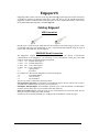
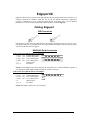
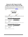
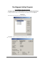
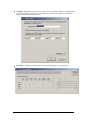
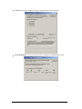
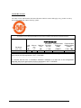
Edgeport ® USB EXPANSION MODULES INDUSTRIAL Installation Guide Models: Edgeport/1i Edgeport/2i Edgeport/2s Edgeport/4s Edgeport/4s Edgeport/8s MEI MEI DC Isolated MEI www.digi.com Table of Contents Table of Contents ...............................................................................................2 Edgeport/1i.........................................................................................................1 Edgeport/2i.........................................................................................................2 Edgeport/2s MEI, Edgeport/4s MEI,Edgeport/4s Isolated, Edgeport/8s MEI...4 Edgeport Driver Installation ..............................................................................6 Interpreting the System Status Light..................................................................6 Mounting Diagrams ...........................................................................................7 The Edgeport Utility Program ...........................................................................8 Understanding Hubs.........................................................................................14 Regulatory & Other Information .....................................................................15 Edgeport/1i Edgeport USB-to-Serial Converters from Digi International provide high-speed serial connectivity via USB port expansion for Windows 2003 Server, 2000, XP, NT 4.0, 98, SE, and Me applications. Edgeport/1i provides one RS-422/485 serial DB-9 port. For more detailed information, as well as the latest manual and technical updates, visit www.digi.com. Cabling Edgeport USB Connection Type A Type B Plug the Type A (flat) end of the USB cable into the USB port located in the back of your PC or into an available USB port on a standard hub or into a Digi International Hubport . Plug the Type B (square) end of the USB cable into the Edgeport. RS422/485 Serial Connection The Edgeport/1i supports RS422/RS485 protocol. To configure the features of RS-422/485 communication on the Edgeport/1i, you will short or leave unconnected certain pins at the DB9 connector of the cable. See the following pin assignment: 3 TA (T-) transmit data negative 7 TB (T+) transmit data positive 8 RA (R-) receive data negative 4 RB (R+) receive data positive 5 signal ground 2 no connect For "jumper wire" based mode configuration, use the following pins: 1 full and half duplex 6 echo on and off 9 line termination The user can switch on and off the following features: Line termination (120 ohm): To enable the line termination resistor, the user connects pin 9 to pin 8. To disable line termination, the user leaves pin 9 unconnected. Full Duplex and Half Duplex: For Full Duplex operation, pin 1 is left unconnected. For Half Duplex operation, the user shorts pin 1 to pin 5 (GND) at the cable connector. Echo On and Echo Off: For Echo On mode, pin 6 is left unconnected. For Echo Off mode, the user shorts pin 6 to pin 5 (GND) at the cable connector. If the drivers are not already installed, go to "Edgeport Driver Installation‖ starting on page 6. Edgeport Industrial Installation Guide (90000409 Rev. J) – Page 1 Edgeport/2i Edgeport USB-to-Serial Converters from Digi International provide high-speed serial connectivity via USB port expansion for Windows 2000, XP, NT 4.0, 98, SE, and Me applications. Edgeport/2i provides a combination of up to two RS-422 and/or RS-485 serial DB-9 ports. For more detailed information, as well as the latest manual and technical updates, visit www.digi.com. Cabling Edgeport USB Connection Type A Type B Plug the Type A (flat) end of the USB cable into the USB port located in the back of your PC or into an available USB port on a standard hub or into a Digi International Hubport. Plug the Type B (square) end of the USB cable into the Edgeport. RS422/485 Serial Connection Cable Connections (DB9 Female) for Full Duplex 3 TA (T-) transmit data negative 7 TB (T+) transmit data positive 8 RA (R-) receive data negative 4 RB (R+) receive data positive 5 signal ground 1, 2, 6, 9 no connect NOTE: For full duplex (in the above diagram) the differential pair TA and TB should be together in one twisted pair and RA and RB should be together in another twisted pair. Cable Connections (DB9 Female) for Half Duplex 3 TA (T-) transmit data negative 7 TB (T+) transmit data positive 8 RA (R-) receive data negative 4 RB (R+) receive data positive 5 signal ground 1, 2, 6, 9 no connect NOTE: Half duplex contains only one twisted pair. Edgeport Industrial Installation Guide (90000409 Rev. J) – Page 2 Configuring the DIP Switches Two Position Switch The two position DIP switch, located on the back panel, connects the signal ground to chassis ground. IMPORTANT: Do not connect signal ground to chassis ground on more than one location in order to prevent ground loops and potentially high currents (figure 1). 1 2 DS1: ON signal ground short to chassis ground OFF signal ground isolated from chassis ground DS2: not used Figure 1: Two Position DIP Switch Eight Position Switch 1 2 3 4 5 6 7 8 The Edgeport/2i also has two sets of eight position DIP switches, located on the back panel next to their corresponding serial port. Figure 2 shows what each switch selects in the ON and OFF positions. Consult the diagrams in figure 3 for various configuration options. For more configuration information, go to the documentation section of our web site at www.digi.com/support. If the drivers are not already installed, go to "Edgeport Driver Installation‖ starting on page 6. ON OFF 1. echo disabled 2. half duplex 3. terminating resistor 4. ---------5. set to ON 6. set to ON 7. not used 8. not used 1. echo enabled 2. full duplex 3. no terminating resistor 4. set to OFF 5. ---------6. ---------7. not used 8. not used Figure 2: Eight Position DIP Switch Option #1: RS-422 to RS-422 Option #2: RS-485 Half Duplex End Unit with Terminating Resistor Option #3: RS-485 Half Duplex Middle Unit X X X X X X Option #4: RS-485 Full Duplex End Unit, Master Option #5: RS-485 Full Duplex End Unit, Slave Option #6: RS-485 Full Duplex Middle Unit, Master X X X X X X Option #7: RS-485 Full Duplex Middle Unit, Slave X X Key: on off user’s chioce X doesn’t matter Figure 3: Various Configurations for the Edgeport/2i DIP Switches Edgeport Industrial Installation Guide (90000409 Rev. J) – Page 3 Edgeport/2s MEI, Edgeport/4s MEI, Edgeport/4s Isolated, Edgeport/8s MEI Edgeport USB-to-Serial Converters from Digi International provide high-speed serial connectivity via USB port expansion for Windows 2000, XP, NT 4.0, 98, 95, SE, and Me applications. Edgeport/2s MEI, Edgeport/4s MEI and Edgeport/8s MEI provide a combination of up to two, four or eight (respectively) RS-232 and/or RS-422 and/or RS-485 serial DB-9 ports. For more detailed information, as well as the latest manual and technical updates, visit www.digi.com. The Isolated version has 2KV DC isolation between all of its ports including the serial ports and the USB port. Cabling Edgeport USB Connection Type A Type B Plug the Type A (flat) end of the USB cable into the USB port located in the back of your PC or into an available USB port on a standard hub or into a Digi International Hubport. Plug the Type B (square) end of the USB cable into the Edgeport. Cable Connections (DB9 Female) for Full Duplex 3 TA 7 TB 8 RA 4 RB 5 1, 2, 6, 9 (T-) (T+) (R-) (R+) transmit data negative transmit data positive receive data negative receive data positive signal ground no connect NOTE: For full duplex (in the above diagram) the differential pair TA and TB should be together in one twisted pair and RA and RB should be together in another twisted pair. Cable Connections (DB9 Female) for Half Duplex 3 TA 7 TB 8 RA 4 RB 5 1, 2, 6, 9 (T-) (T+) (R-) (R+) transmit data negative transmit data positive receive data negative receive data positive signal ground no connect NOTE: Half duplex contains only one twisted pair. Edgeport Industrial Installation Guide (90000409 Rev. J) – Page 4 DB9 RS-232 Pin Assignment 1 DCD 2 RD 3 TD 4 DTR 5 SGND data carrier detect receive data transmit data data terminal ready ground 6 DSR 7 RTS 8 CTS 9 RI data set ready request to send clear to send ring indicator Configuring the Port Flags The Edgeport/2s MEI, Edgeport/4s MEI, Edgeport/8s MEI and the Edgeport/4s Isolated, which support RS-232, RS-422 and RS-485, are configured using the Edgeport Utility program. Before configuring, make sure that the drivers have been installed and that the device is connected to your computer. Open edgeport.exe, select the Edgeport that you want to configure, and click on the Port Flag Configuration button. The drop down boxes under the Industrial Settings allow you to select from the following options for each port listed: RS232 RS422: No Terminating Resistor RS422: Terminating Resistor RS485: Half Duplex, End Unit, Echo RS485: Half Duplex, End Unit, No Echo RS485: Half Duplex, Middle Unit, Echo RS485: Half Duplex, Middle Unit, No Echo RS485: Full Duplex, End Unit, Master RS485: Full Duplex, End Unit, Slave RS485: Full Duplex, Middle Unit, Master RS485: Full Duplex, Middle Unit, Slave If the drivers are not already installed, go to "Edgeport Driver Installation‖ starting on page 6. Edgeport Industrial Installation Guide (90000409 Rev. J) – Page 5 Edgeport Driver Installation For Windows XP, Server 2003, Server 2008, and Vista Note: You must be logged into an account with administrator privileges before proceeding. Note: Please go to www.digi.com to download software for older Operating Systems. 1. Connect the USB cable. (Refer to the Table of Contents to locate the cabling instructions for your specific Edgeport model.) If your computer is connected to the internet, the latest Microsoft certified drivers will be automatically downloaded from the Microsoft driver update server. If not, continue with step 3. 2. Insert the ―Edgeport Driver‖ CD into your CD-ROM drive. In most cases the drivers will be automatically installed from the CD. If not, proceed with step 4. 3. When the Found New Hardware Wizard appears, select Install from a list or specific location (Advanced) and click Next. 4. Select Search for a suitable driver for my device and click Next. 5. Select Specify a location and click Next. 6. Type in <CD drive letter>:\drivers and click OK. 7. Confirm that Windows is pointing to <CD drive letter>:\drivers. Then click Next 8. Wait while Windows finishes installing the driver files and click Finish to complete the installation. Your new COM port(s), numbered sequentially following the existing ports in your system, is/are ready. Interpreting the System Status Light For All Edgeports except the Edgeport/1i Red Amber Green This light signifies a loss of USB communication with the host. If the loss is due to unplugging the unit, when it is reconnected the light will blink red a few moments before turning green. Otherwise, the light indicates a problem with the drivers, which may need to be reinstalled. The red light will also blink during installation until the installation is complete. This light signifies serial port activity on the Edgeport. The amber light may also flash briefly during installation. This light indicates the serial ports are successfully set up and the Edgeport is operating normally. Edgeport Industrial Installation Guide (90000409 Rev. J) – Page 6 Mounting Diagrams For all Edgeports except the Edgeport/1i Rack Mount Kit* Under-Shelf Mounting Bracket* *Nuts, bolts, and screws are not included. Edgeport Industrial Installation Guide (90000409 Rev. J) – Page 7 The Edgeport Utility Program For All Windows Operating Systems The Edgeport configuration utility program (edgeport.exe) allows you to manage the serial ports of your Edgeport product. Note that with Windows NT you must have administrative privileges in order to change the COM port settings. For more information, see the Support section at www.digi.com. General Tab The General tab in this utility allows you to do the following: Information - Check the manufacturing information pertaining to your device. Edgeport Industrial Installation Guide (90000409 Rev. J) – Page 8 Configure - Reassign the physical port on your device to any available Windows COM port number from 1 to 255 and give your device a user friendly Device Name. This capability is particularly helpful if you have more than one device. Port Flags - Configure performance options and special functionality on a per-port basis. Edgeport Industrial Installation Guide (90000409 Rev. J) – Page 9 Low Latency: (930 based Edgeport only) Normally the UART will interrupt when the receiver has been idle for 4 character times. (For example 4ms at 9600) As long as data is being received the UART will continue to buffer them until its internal FIFO is full (~56 bytes). This flag causes the Edgeport to poll the RX FIFO for received bytes. If any bytes are available they will be sent to the driver without any delay. Remap Baud: (All operating systems - 930 and TI based Edgeport) Setting the baud rate to 1200 baud will result in 230400 baud Ignore Flush: (Windows NT/2K/XP 930 and TI) If an application sends IRP_MJ_FLUSH_BUFFERS it will be ignored. Excerpt from Microsoft documentation: Drivers of devices with internal caches for data and drivers that maintain internal buffers for data must handle this request. When Sent Receipt of a flush request indicates that the driver should flush the device's cache or its internal buffer, or, possibly, should discard the data in its internal buffer. Operation The driver transfers any data currently cached in the device or held in the driver's internal buffer(s) before completing the flush request. The driver of an input-only device that buffers data internally might simply discard the currently buffered device data before completing the flush IRP, depending on the nature of its device. Fast Writes: (All operating systems - 930 and TI based Edgeport) When an application sends a write to the driver, by default the Edgeport driver will wait until all data has been transmitted out of the Edgeport device before completing the write. When the Fast Writes flag is set, we complete the write even if data is still buffered in the driver and the Edgeport device. Fast Reads: This flag is used when an application requires that a read complete immediately. In the read immediate case, the Edgeport driver will send a request to the Edgeport device asking for any buffered data to be sent up. This buffered data will be included when the read completes. If this flag is set, the driver will not query the Edgeport device for additional data. Disable Plug & Play: (Windows 2k/XP only) Do not let the serial port enumerator detect devices plugged into the Edgeport. Ignore Tx Purge: The IOCTL_SERIAL_PURGE request cancels the specified requests and deletes data from the specified buffers. The purge request can be used to cancel all read requests and write requests and to delete all data from the read buffer and the write buffer. When the Ignore Tx Purge flag is set the SERIAL_PURGE_TXCLEAR command will be ignored. The function will not purge the write buffer. Timer Logic: (Windows 9x only) If application uses PortSetReadCallBack(), the notification routine will only be called when the number of bytes in the receive buffer is greater then the RX trigger. The Microsoft serial VxD also implements a timer that will trigger and call the notification routine if some amount of data is available in the RX buffer but no new data has been received for ~200ms (receiver is no longer active). We do not enable this behavior by default because of the nature of Edgeport buffering. But if you set the flag we will complete the read when we detect ~200 ms no activity. Here is a comment from the code: If the receiver is active then do not complete this read. The problem is that the Edgeport buffers the RX bytes and we poll the driver. If we do not receive any bytes in 200ms we may report an erroneous event even if there are available bytes in the Edgeport device or driver. Edgeport Industrial Installation Guide (90000409 Rev. J) – Page 10 Test Ports - Perform a confidence test on the internal workings of the serial ports. Power Management – Turn on and off the power for Hubports with USB PlusPower ports Edgeport Industrial Installation Guide (90000409 Rev. J) – Page 11 Port Status – Provide the status of a selected (highlighted) serial port. The Poll Interval is the number of seconds between updates of this window. This is also the number of seconds between each entry in the log file. To create a log file, click the Start Logging button and enter a filename for the log file. This file will contain all of the information displayed in the Port Status window until the Stop Logging button is clicked. Refresh – Scan for ports. Note that NT 4.0 does not automatically scan. Version Tab The Version tab allows you to check the file information pertaining to the software. Advanced Tab The Advanced tab allows you to do the following: Edgeport Industrial Installation Guide (90000409 Rev. J) – Page 12 Uninstall the drivers. Enable Event Logging – Place event messages in system event log. Configure how COM ports will be assigned. The driver supports COM port number assignment in two ways: 1. Assign COM ports based on converter serial number. This is the default setting. In this mode, the driver uses the serial number of each converter to uniquely identify it, and the COM port assignments for a given converter are based on its serial number. No matter which physical USB port a converter is plugged into, it will maintain its assigned COM port numbers. 2. Assign COM ports based on physical USB port. In this mode, the driver identifies a converter based on the physical USB port it is plugged into. This effectively assigns COM port numbers to physical USB ports. No matter which converter is plugged into a given USB port, it will use the COM port numbers assigned to that USB port. This permits a converter to be to be replaced with a new unit, and, although the new unit has a different serial number, it will receive the same COM port assignments as the old unit because they were both plugged into the same USB port. When using this mode, converters are identified not by their serial number, but by a 2-7 digit number that identifies which USB port it is plugged into. After changing this setting, you will need to reboot before the change takes effect. Edgeport Industrial Installation Guide (90000409 Rev. J) – Page 13 Understanding Hubs Hubs, critical components in the USB architecture, are wiring concentrators that enable the attachment of multiple devices, thus converting a single attachment point into multiple attachment points. USB architecture allows a cascaded multiple hub configuration with certain power limitations (explained later in this section). See figure 1. PC Host Hubport Edgeport Edgeport Hubport Edgeport bu s-powered hub joystick scanner mouse Figure 1: Example of a Typical Hub Configuration Each hub has an upstream port, connecting to the host, and multiple downstream ports, connecting to downstream devices, possibly including other hubs. A hub can detect attachment and detachment of downstream devices and enable and monitor the distribution of the power to downstream devices via their integral hardware and the operating system. Each USB device reports its power requirements to the operating system, which then enables and disables the device as a function of its power requirements and the amount of available power. High powered devices typically need to be connected to a self-powered hub, such as the Hubport, which obtains power from its external power supply and provides up to 500 mA for each downstream port. Only low powered devices, such as a mouse, can be connected to a bus-powered hub, which obtains power from its upstream host and provides up to 100 mA for each downstream port. Due to the limited available power for bus-powered hubs, cascading two bus-powered hubs is an illegal topology, and devices connected to the second hub will not function. USB specifications limit the connection of a bus-powered hub to a self-powered hub or host only. According to the USB Specification, the maximum limit of hubs cascaded in series cannot exceed five. In other words, you may have a maximum of five hubs between any device and the host. This does NOT mean that the maximum number of hubs in a system is five. Indeed, up to seven hubs can be connected parallel at any given level. You must tally both external and embedded hubs when counting downstream hubs. Edgeport Industrial Installation Guide (90000409 Rev. J) – Page 14 Regulatory & Other Information © 2006 Digi, Digi International, the Digi logo, the Digi Connectware logo, Edgeport, and Hubport are either trademarks or registered trademarks of Digi International, Inc. in the United States and/or other countries. All other trademarks are the property of their respective holders. Information in this documentation is subject to change without notice and does not represent a commitment on the part of Digi International. Digi International provides this document ―as is,‖ without warranty of any kind, either expressed or implied, including, but not limited to, the particular purpose. Digi International may make improvements and/or changes to this documentation or to the product(s) and/or program(s) described in this documentation at any time. Digi International assumes no responsibility of any errors, technical inaccuracies, or typographical errors that may appear in this documentation, nor liability for any damages arising out of its use. Changes are made periodically to the information herein; these changes may be incorporated in new editions of the publication. For U.S. Government use: Any provision of this document and associated computer programs to the U.S. Government is with ―Restricted Rights.‖ Use, duplication, or disclosure by the government is subject to the restrictions set forth in, subparagraph (c) (1) (ii) of the Rights in Technical Data and Computer Software clause of DFARS 52.277-7013. For non-U.S. Government use: These programs are supplied under a license. They may be used, disclosed, and/or copied only as supplied under such license agreement. Any copy must contain the above copyright notice and restricted rights notice. Use, copying, and/or disclosure of the programs is strictly prohibited unless otherwise provided for in the license agreement. Federal Communications Commission (FCC) Regulatory Information (USA only) This equipment has been tested and found to comply with the limits for a Class B digital device, pursuant to Part 15 of the FCC Rules. These limits are designed to provide reasonable protection against harmful interference in a residential installation. This equipment generates, uses, and can radiate radio frequency energy and, if not installed and used in accordance with the instructions, may cause harmful interference to radio communications. However, there is no guarantee that interference will not occur in a particular installation. If this equipment does cause harmful interference to radio or television reception, which can be determined by turning the equipment off and on, the user is encouraged to correct the interference by one or more of the following measures: Reorient or relocate the receiving antenna. Increase the separation between the equipment and the receiver. Connect the equipment into an outlet that is on a circuit different from the receiver. Consult the dealer or an experienced radio/TV technician for help. Warning: The connection of a non-shielded interface cable to this equipment will invalidate the FCC Certification for this device. FCC Regulation - Part 15 Declaration of Conformity (DoC) This device complies with the requirements of the Code of Federal Regulations listed below: FCC Title 47 CFR, Part 15 Class B for a digital device. Operation is subject to the following two conditions: This device may not cause harmful interference, and This device must accept any interference received, including interference that may cause undesired operation. Department of Communication (DOC) Notice (Canada only) This Class B digital apparatus meets the requirements of the Canadian Interference-Causing Equipment Regulations. Cet appareil numérique de la Classe B respecte toutes les exigences du Règlement sur le matériel brouiller du Canada. European Community - CE Mark Declaration of Conformity (DOC) According to ISO/IEC Guide 22 and EN 45014 Manufacturer’s Name: Digi International Manufacturer’s Address: 11001 Bren Road East Minnetonka, MN 55343 USA Edgeport Industrial Installation Guide (90000409 Rev. J) – Page 15 declares that the product Product Name(s): Edgeport/1i Model Number(s): 301-1001-31 Product Name(s): Edgeport/2i Model Number(s): 301-1000-12 Product Name: Edgeport/2s MEI Model Number(s): 301-1000-92 Product Name: Edgeport/4s MEI Model Number(s): 301-1000-94 Product Name: Edgeport/4s Isolated Model Number(s): 301-1000-95 Product Name: Edgeport/8s MEI Model Number(s): 301-1002-98 Product Options: All Conforms to the relevant EU Directives listed here: EMC Directive 2004/108/EC| Low Voltage Directive 2006/95/EC R&TTE 1999/5/EC using the relevant section of the following EU standards and other normative documents: EMC: EN55022 Class B(2006) EN55024 (1998+A1,A2) EN61000-3-2(2000+A2) EN61000-3-3(1995+A1,A2) Safety: EN 60950 (2001) The following summarizes the specifications and requirements for EN55024, EN55022 Class B & CISPR 22 Class B emission and immunity tests. If the actual test levels are higher or different than required, these levels are listed in the appropriate tables. EN55022 Test Specification EN55022 Requirement Radiated Emissions — Class B Conducted Emissions CISPR 22 Class B Test Specification EN55024 Requirement Electrostatic Discharge EN61000-4-2 +2,+4 kV direct contact +2,+4 kV and +8kV air (insulated surfaces) +2,+4 kV(HCP&VCP) indirect Radiated Immunity EN61000-4-3 3 V/m, 80Mhz-1000Mhz, amp mod 1kHz sine wave at 80% Electrical Fast Transient Burst EN61000-4-4 +0.5kV,+ 1kV (A/C) +0..5kV (I/O) Surge EN61000-4-5 +0.5kV,+ 1kV 1kV Conducted Immunity EN61000-4-6 3Vrms, .150Mhz to 80Mhz, amp mod. 1kHz wave at 80% Magnetic Immunity EN61000-4-8 1 A/m Not Applicable Voltage Dips & Interrupts EN61000-4-11 >95%10ms, 30%@500ms & >95%@5sec reduction at rated voltage EN 55024 European Contact Digi International Joseph-von-Fraunhofer Str. 23 44227 Dortmund, GERMANY 49-231-9747-0 UL/CSA Safety Information This device complies with the requirements of following safety standards below: UL 60950-1 CSA C22.2 No.60950-1 Quality Manager Austin, Texas – October 2007 Edgeport Industrial Installation Guide (90000409 Rev. H) – Page 16 China RoHS statement: The Table of Toxic and Hazardous Substances/Elements and their Content shall apply to any product covered by this manual and labeled with the following symbol: The Table of Toxic and Hazardous Substances/Elements and their Content as required by China’s Management Methods for the Control of Pollution from Electronic Information Products Part Name (部件名称) 301-1002-08 Lead (Pb) (铅) X Toxic and Hazardous Substances or Elements (有毒有害物质或元素) Hexavalent Polybrominated Polybrominated Cadmium Chromium biphenyls diphenyl ethers Mercury (Cd) (Cr (VI)) (PBB) (PBDE) (Hg) (镉) (六价铬) (多溴联苯) (多溴二苯醚) (汞) O O O O O O: Indicates that this toxic or hazardous substance contained in all of the homogeneous materials for this part is below the limit requirement in SJ/T 11363-2006. 表示该有毒有害物质在该部件所有均质材料中的含量均在SJ/T11363-2006 标准规定的限量要求以下. X: Indicates that this toxic or hazardous substance contained in at least one of the homogeneous materials used for this part is above the limit requirement in SJ/T 11363-2006. 示该有毒有害物质至少在该部件的某一均质材料中的含量超出SJ/T11363-2006 标准规定的限量要求. Edgeport Industrial Installation Guide (90000409 Rev. H) – Page 17 Digi International 11001 Bren Road East Minnetonka, MN 55343 [email protected] www.digi.com Corporate Headquarters: 952-912-3444 877-912-3444 Fax: 952-912-4952 Digi Europe: +49-231-9747-0 Digi Hong Kong: +852-2833-1008 Digi North America: 877-912-3444