1
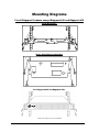
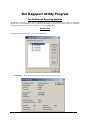
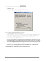
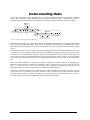
Edgeport ® USB EXPANSION MODULES Installation Guide Edgeport/1 Edgeport/2 Edgeport/4 Edgeport/8 Edgeport/8r Edgeport/8rr Edgeport/421 Edgeport/21 Edgeport/42 Edgeport/412 Edgeport/416 Edgeport/2c Edgeport/21c Edgeport/22c www.digi.com Table of Contents Table of Contents.................................................................................................................2 Edgeport Products................................................................................................................1 Edgeport /1, Edgeport/2, Edgeport/4, Edgeport/8, Edgeport/8r, Edgeport/8rr....................2 Edgeport/21, Edgeport/42, Edgeport/421 ............................................................................3 Edgeport/412, Edgeport/416 ................................................................................................5 Edgeport/2c ..........................................................................................................................6 Edgeport/21c, Edgeport/22c ................................................................................................7 Edgeport Driver Installation ................................................................................................8 The System Status Light ....................................................................................................10 Mounting Diagrams ...........................................................................................................11 The Edgeport Utility Program ...........................................................................................12 Understanding Hubs...........................................................................................................18 Regulatory & Other Information .......................................................................................19 Edgeport Products Edgeport USB-to-Serial Converters offer an out-of-the-box alternative to serial cards for easy plug-and-play COM port expansion. Multiple serial, parallel and USB ports can be added to a PC, thin client or server in minutes — without opening the chassis or reconfiguring and rebooting the system. Its feature-rich design, reliable performance and unmatched operating system support (Windows NT 4.0, CE, XP, 2000, 2003 Server and more) make the Edgeport ideal for mission-critical enterprise applications. Edgeport Installation Guide (90000403 Rev. D) – Page 1 Edgeport /1, Edgeport/2, Edgeport/4, Edgeport/8, Edgeport/8r, Edgeport/8rr The Edgeport/2, Edgeport/4, Edgeport/8, Edgeport/8r, and Edgeport/8rr from Digi International are intelligent, stackable expansion modules that connect to a PC or server running Windows 95, 98, SE, CE, Me, NT 4.0, 2000, or Windows XP via the Universal Serial Bus (USB), providing high-speed serial connectivity. For more detailed information as well as the latest manual and technical updates, visit www.digi.com/support. Cabling Edgeport Type A Type B Plug the Type A end of the USB cable into the USB port located in the back of your PC or into an available USB port on a standard hub or into a Digi Hubport. Plug the Type B end of the USB cable into the back of the Edgeport. If the drivers are not already installed, go to "Edgeport Driver Installation” on page 8. Edgeport/8r RJ-45 Pin Assignments Use the table below to find the RJ-45 pin assignments for your Edgeport/8r. Signal RTS DSR DCD RXD TXD SG DTR CTS Description Request to Send Data Set Ready Data Carrier Detect Received Data Transmitted Data Signal Ground Data Terminal Ready Clear to Send DTE Use Output Input Input Input Output Reference Output Input Pin # 1 2 3 4 5 6 7 8 Edgeport/8rr RJ-12 Pin Assignments Use the table below to find the RJ-12 pin assignments for your Edgeport/8rr. Signal RTS CGND TXD RXD GND CTS Description Request to Send Chassis Ground Transmitted Data Received Data Ground Clear to Send DTE Use Output Reference Output Input Reference Input Pin # 1 2 3 4 5 6 Edgeport Installation Guide (90000403 Rev. D) – Page 2 Edgeport/21, Edgeport/42, Edgeport/421 The Edgeport/21, Edgeport/42, and Edgeport/421 are multi-connector converters for mobile and high-end workstation users who need to attach multiple serial (RS-232) ports, a printer port, and USB peripherals to a single USB upstream connector. Cabling Edgeport Type A Type B The Edgeport/42 and Edgeport/421 operate as self-powered hubs, requiring a power supply to function. (For more information about hubs, see “Understanding Hubs” on page 18.) Connect one end of the power supply into the back of your Edgeport and the other end into an AC outlet.* The Edgeport/21 derives its power from the host machine through the USB cable, and thus, does not require a power supply. To connect your Edgeport to a PC or Hub, plug the Type A end of the USB cable into the USB port located in the back of your PC or into an available USB port on a standard hub or into a Digi Hubport. Plug the Type B end of the USB cable into the back of the Edgeport. To connect a USB device to your Edgeport, plug the Type A end of the USB cable into one of the Edgeport/421 or Edgeport/42 USB Type A slots and the Type B end of the USB cable into the device. * Power to the Edgeport/421 may be supplied by a UL Listed Direct Plug-In Power Unit or Information Technology Equipment Rated Power Unit rated 5 V dc, at least 2.5 A if used in the U.S. and Canada or a power supply with similar rating and approved by your local safety code if it is used elsewhere. For polarity, see diagram to the right. + - Installing the Hub Drivers For Windows 95 Users After plugging Edgeport into your PC, the Update Device Driver Wizard for installing the generic USB hub may appear. If so, follow the recommended on screen instructions. Otherwise, Windows 95 will bring up the Update Device Driver Wizard for installing the Edgeport drivers, in which case you may proceed to “Edgeport Driver Installation” on page 8. For Windows 98, CE, SE, Me, 2000 and XP Users After following the instructions described in “Cabling Edgeport” on this page, hub installation will be complete and you may continue with “Edgeport Driver Installation” on page 8. For Windows NT Users No separate process is required. Go to “Edgeport Driver Installation” on page 8. Edgeport Installation Guide (90000403 Rev. D) – Page 3 Using the Printer Port For Windows 95, 98, CE, SE, Me, 2000, XP and NT Users The parallel port on your Edgeport/421 and Edgeport/21 supports only printers. To use your newly installed printer port: 1. From the Start menu, choose “Settings” and then “Printers.” 2. Right click on the printer you wish to use on your new port and select “Properties.” 3. In the Details tab, click on the drop down list box under “Print to the following port” and choose “USBLPT1”, then click “OK.” Edgeport Installation Guide (90000403 Rev. D) – Page 4 Edgeport/412, Edgeport/416 The Edgeport/412 and Edgeport/416 utilize a standards-based USB bus for connectivity, unlike many serial card products which require additional external proprietary hardware to support the same number of devices. This Edgeport also supplies four USB ports, providing users with a built-in migration path as peripherals become USBready. The converters can be rack mounted and easily daisy-chained together. These Edgeport converters are available in two models: one with DB25 connectors and one with DB9 connectors. The two models are functionally equal, but differ in the type and placement of the connectors. Cabling Edgeport Type A Type B Connect one end of the power supply into the back of your Edgeport and the other end into an AC outlet.* To connect your Edgeport to a PC or Hub, plug the Type A end of the USB cable into the USB port located in the back of your PC or into an available USB port on a standard hub or into a Digi Hubport. Plug the Type B end of the USB cable into the back of the Edgeport/412 or 416. To connect a USB device to your Edgeport, plug the Type A end of the USB cable into one of the Edgeport’s USB Type A slots and the Type B end of the USB cable into the device (e.g. a Rapidport, Hubport, Edgeport/421, etc.). * Power to the Edgeport-DB25 and Edgeport-DB9 may be supplied by a UL Listed Direct Plug-In Power Unit or Information Technology Equipment Rated Power Unit rated 5 V dc, at least 2.9 A if used in the U.S. and Canada or a power supply with similar rating and approved by your local safety code if it is used elsewhere. For polarity, see diagram to the right. If the drivers are not already installed, go to "Edgeport Driver Installation” on page 8. Edgeport Installation Guide (90000403 Rev. D) – Page 5 + - Edgeport/2c The Edgeport/2c is an intelligent expansion module that connects to a PC or server running Windows 95, 98, SE, CE, Me, NT 4.0, 2000 and Windows XP via the Universal Serial Bus (USB), providing high-speed serial connectivity. For more detailed information as well as the latest manual and technical updates, visit our website at www.digi.com. Cabling Edgeport Type A Plug the USB cable (with the Type A plug) into a USB port located on your PC or into an available USB port on a standard hub or into a Digi Hubport. If the drivers are not already installed, go to "Edgeport Driver Installation” on page 8. Edgeport Installation Guide (90000403 Rev. D) – Page 6 Edgeport/21c, Edgeport/22c The Edgeport/21c and Edgeport/22c are compact, multi-connector converters for mobile and high-end workstation users who need to attach multiple serial (RS-232) ports, a printer port, and USB peripherals to a single USB upstream connector. Cabling Edgeport Type A These Edgeports operate as bus-powered hubs. For more information about hubs, see the section “Understanding Hubs” on page 18. To connect your Edgeport, plug the USB cable (with the Type A plug) into a USB port located on your PC or into an available USB port on a standard hub or into a Digi Hubport. Installing the Printer Port For Windows 95, 98, CE, SE, Me, 2000, XP and NT Users The parallel port on your Edgeport/21c supports only printers. To use your newly installed printer port: 1. From the Start menu, choose “Settings” and then “Printers.” 2. Right click on the printer you wish to use on your new port and select “Properties.” 3. In the Details tab, click on the drop down list box under “Print to the following port” and choose “USBLPTx” or “USB00x” (depending on OS), then click “OK.” Installing the Hub Drivers For Windows 98, CE, SE, Me, 2000, and XP Users After following the instructions described in “Cabling Edgeport” above, hub installation will be complete and you may continue with “Edgeport Driver Installation” on page 8. For Windows NT Users No separate process is required. Go to “Edgeport Driver Installation” on page 8. For Windows 95 Users After plugging Edgeport into your PC, the Update Device Driver Wizard for installing the generic USB hub may appear. If so, follow the recommended on screen instructions. Otherwise, Windows 95 will bring up the Update Device Driver Wizard for installing the Edgeport drivers, in which case you may proceed to “Edgeport Driver Installation” on page 8. Edgeport Installation Guide (90000403 Rev. D) – Page 7 Edgeport Driver Installation For Windows XP, 2000, and 2003 Server Please note that you must be logged into an account with administrator privileges before proceeding. 1. Connect the USB cable. (Refer to the Table of Contents to locate the cabling instructions for your specific Edgeport model.) If your computer is connected to the internet, the latest Microsoft certified drivers will be automatically downloaded from the Microsoft driver update server. If not, continue with step 3. 2. Insert the “Edgeport Driver” CD into your CD-ROM drive. In most cases the drivers will be automatically installed from the CD. If not, proceed with step 4. 3. When the Found New Hardware Wizard appears, select “Install from a list or specific location (Advanced)” and click “Next”. 4. Select “Search for a suitable driver for my device” and click “Next”. 5. Select “Specify a location” and click “Next”. 6. Type in <CD drive letter>:\Win2k and click “OK”. 7. Confirm that Windows is pointing to <CD drive letter>:\Win2k. Then click “Next”. Note: Drivers installed from the CD have received “Designed for Windows 2000” certification. Drivers downloaded from our web site may be pending certification. If so, Windows 2000 will display a warning: Digital Signature Not Found. Click “Yes” to continue with driver installation. If you click “No” you will need to contact Digi Technical Support before installing your USB Plus Series product. 8. Windows will then finish installing the driver files. 9. Click “Finish” to complete the driver installation. Installation is complete when no more dialogs appear. Your new COM port(s), numbered sequentially following the existing ports in your system, is/are ready. For Windows 98, and Me 1. After connecting the USB cable, insert the "Edgeport Driver" CD into your CD-ROM drive. (Refer to the Table of Contents to locate the cabling instructions for your specific Edgeport model.) 2. When the Add New Hardware Wizard appears, click "Next". 3. Select "Search for the best driver for your device" and click "Next". 4. Select "Specify a location" and type in <CD drive letter>:\Win98. Then click "Next". 5. Confirm that Windows is pointing to <CD drive letter>:\Win98. Click "Next". Windows will then copy over the driver files. 6. Click "Finish" to complete the driver installation. Installation is complete when no more dialogs appear. Your new COM port(s), numbered sequentially following the existing ports in your system, is/are ready. For Windows NT 4.0 Because Microsoft does not support USB in NT4.0, Digi supplies a set of USB drivers that will be installed along with the necessary Edgeport drivers. NOTE: You must install the drivers using an account that has administrative privileges! Edgeport Installation Guide (90000403 Rev. D) – Page 8 To install the USB stack and Edgeport drivers: 1. Insert the “Edgeport Driver” CD into your CD-ROM drive. 2. When the welcome dialog appears, click the “Install Driver” button. Once the driver installation program has begun, follow the on screen instructions. 3a. If you are installing drivers for the first time: An Information dialog informs you that the installation was successful. After clicking “OK”, the installation is complete. 3b. If you are replacing existing Edgeport drivers: Follow the on-screen instructions. Note that, before beginning the installation of the drivers, all applications with open ports must be closed and all USB devices unplugged. If you close all the applications and unplug all the USB devices, then you will not need to reboot for the new drivers to take effect immediately. If any applications are left open or USB devices plugged in, you may choose to abort the installation or to continue and be required to reboot before the upgrade can take effect. Note that because Windows NT 4.0 is not Plug-and-Play, you will not see a pop-up dialog box indicating that new hardware has been found. You may verify correct installation with the Edgeport Utility (see page 12) or the USB Status Utility (Viewer), as described below. The USB Status Utility can be accessed by clicking the USB icon in your system tray or by clicking on Start, Programs, Inside Out Networks Utilities, USB Status Utility. This utility lists all the USB devices installed on your PC and provides other relevant information for each device. You may also use this utility to create a log file. For Windows 95 1. After connecting the USB cable, the Update Device Driver Wizard dialog appears. Click "Next" to continue. 2. Insert the "Edgeport Driver" CD into your CD-ROM drive. 3. After Windows fails to locate the drivers on your floppy disk drive, click "Other Locations...". 4. When the Select Other Location dialog appears, type <CD drive letter>:\Win95 and click "OK". 5. Confirm that Windows has found the correct driver location and click "Finish". 6. When Windows prompts you for the driver disk, click "OK". 7. At the next Windows prompt, type <CD drive letter>:\Win95 and click "OK". Installation is complete when no more dialogs appear. Your new COM port(s), numbered sequentially following the existing ports in your system, is/are ready. Edgeport Installation Guide (90000403 Rev. D) – Page 9 The System Status Light For All Edgeports except the Edgeport/1 Red This light signifies a loss of USB communication with the host. If the loss is due to unplugging the unit, when it is reconnected the light will blink red a few moments before turning green. Otherwise, the light indicates a problem with the drivers, which may need to be reinstalled. The red light will also blink during installation until the installation is complete. Amber This light signifies serial port activity on the Edgeport. The amber light may also flash briefly during installation. Green This light indicates the serial ports are successfully set up and the Edgeport is operating normally. Edgeport Installation Guide (90000403 Rev. D) – Page 10 Mounting Diagrams For all Edgeport Products except Edgeport/416 and Edgeport/412 Rack Mount Kit* Under-Shelf Mounting Bracket* For Edgeport/416 and Edgeport/412* *Nuts, bolts, and screws are not included. Edgeport Installation Guide (90000403 Rev. D) – Page 11 The Edgeport Utility Program For All Windows Operating Systems The Edgeport configuration utility program (edgeport.exe) allows you to manage the serial ports of your Edgeport product. Note that with Windows NT you must have administrative privileges in order to change the COM port settings. For more information, see the Support section at www.digi.com. General Tab The General tab in this utility allows you to do the following: • Information - Check the manufacturing information pertaining to your device. Edgeport Installation Guide (90000403 Rev. D) – Page 12 • Configure - Reassign the physical port on your device to any available Windows COM port number from 1 to 255 and give your device a user friendly Device Name. This capability is particularly helpful if you have more than one device. • Port Flags - Configure performance options and special functionality on a per-port basis. Edgeport Installation Guide (90000403 Rev. D) – Page 13 Low Latency: (930 based Edgeport only) Normally the UART will interrupt when the receiver has been idle for 4 character times. (For example 4ms at 9600) As long as data is being received the UART will continue to buffer them until its internal FIFO is full (~56 bytes). This flag causes the Edgeport to poll the RX FIFO for received bytes. If any bytes are available they will be sent to the driver without any delay. Remap Baud: (All operating systems - 930 and TI based Edgeport) Setting the baud rate to 1200 baud will result in 230400 baud Ignore Flush: (Windows NT/2K/XP 930 and TI) If an application sends IRP_MJ_FLUSH_BUFFERS it will be ignored. Excerpt from Microsoft documentation: Drivers of devices with internal caches for data and drivers that maintain internal buffers for data must handle this request. When Sent Receipt of a flush request indicates that the driver should flush the device's cache or its internal buffer, or, possibly, should discard the data in its internal buffer. Operation The driver transfers any data currently cached in the device or held in the driver's internal buffer(s) before completing the flush request. The driver of an input-only device that buffers data internally might simply discard the currently buffered device data before completing the flush IRP, depending on the nature of its device. Fast Writes: (All operating systems - 930 and TI based Edgeport) When an application sends a write to the driver, by default the Edgeport driver will wait until all data has been transmitted out of the Edgeport device before completing the write. When the Fast Writes flag is set, we complete the write even if data is still buffered in the driver and the Edgeport device. Fast Reads: This flag is used when an application requires that a read complete immediately. In the read immediate case, the Edgeport driver will send a request to the Edgeport device asking for any buffered data to be sent up. This buffered data will be included when the read completes. If this flag is set, the driver will not query the Edgeport device for additional data. Disable Plug & Play: (Windows 2k/XP only) Do not let the serial port enumerator detect devices plugged into the Edgeport. Ignore Tx Purge: The IOCTL_SERIAL_PURGE request cancels the specified requests and deletes data from the specified buffers. The purge request can be used to cancel all read requests and write requests and to delete all data from the read buffer and the write buffer. When the Ignore Tx Purge flag is set the SERIAL_PURGE_TXCLEAR command will be ignored. The function will not purge the write buffer. Timer Logic: (Windows 9x only) If application uses PortSetReadCallBack(), the notification routine will only be called when the number of bytes in the receive buffer is greater then the RX trigger. The Microsoft serial VxD also implements a timer that will trigger and call the notification routine if some amount of data is available in the RX buffer but no new data has been received for ~200ms (receiver is no longer active). We do not enable this behavior by default because of the nature of Edgeport buffering. But if you set the flag we will complete the read when we detect ~200 ms no activity. Edgeport Installation Guide (90000403 Rev. D) – Page 14 Here is a comment from the code: If the receiver is active then do not complete this read. The problem is that the Edgeport buffers the RX bytes and we poll the driver. If we do not receive any bytes in 200ms we may report an erroneous event even if there are available bytes in the Edgeport device or driver. • Test Ports - Perform a confidence test on the internal workings of the serial ports. • Power Management – Turn on and off the power for HubPorts with USB PlusPower ports Edgeport Installation Guide (90000403 Rev. D) – Page 15 • Port Status – Provide the status of a selected (highlighted) serial port. The Poll Interval is the number of seconds between updates of this window. This is also the number of seconds between each entry in the log file. To create a log file, click the Start Logging button and enter a filename for the log file. This file will contain all of the information displayed in the Port Status window until the Stop Logging button is clicked. • Refresh – Scan for ports. Note that NT 4.0 does not automatically scan. Version Tab The Version tab allows you to check the file information pertaining to the software. Edgeport Installation Guide (90000403 Rev. D) – Page 16 Advanced Tab The Advanced tab allows you to do the following: • Uninstall the drivers. • Enable Event Logging – Place event messages in system event log. • Configure how COM ports will be assigned. The driver supports COM port number assignment in two ways: 1. Assign COM ports based on converter serial number. This is the default setting. In this mode, the driver uses the serial number of each converter to uniquely identify it, and the COM port assignments for a given converter are based on its serial number. No matter which physical USB port a converter is plugged into, it will maintain its assigned COM port numbers. 2. Assign COM ports based on physical USB port. In this mode, the driver identifies a converter based on the physical USB port it is plugged into. This effectively assigns COM port numbers to physical USB ports. No matter which converter is plugged into a given USB port, it will use the COM port numbers assigned to that USB port. This permits a converter to be to be replaced with a new unit, and, although the new unit has a different serial number, it will receive the same COM port assignments as the old unit because they were both plugged into the same USB port. When using this mode, converters are identified not by their serial number, but by a 2-7 digit number that identifies which USB port it is plugged into. After changing this setting, you will need to reboot before the change takes effect. Edgeport Installation Guide (90000403 Rev. D) – Page 17 Understanding Hubs Hubs, critical components in the USB architecture, are wiring concentrators that enable the attachment of multiple devices, thus converting a single attachment point into multiple attachment points. USB architecture allows a cascaded multiple hub configuration with certain power limitations (explained later in this section). See figure 1. PC Host Hubpo rt Edgeport Edgeport Hu bp ort Ed geport bu s-powered hub joystick scanner mouse Figure 1: Example of a Typical Hub Configuration Each hub has an upstream port, connecting to the host, and multiple downstream ports, connecting to downstream devices, possibly including other hubs. A hub can detect attachment and detachment of downstream devices and enable and monitor the distribution of the power to downstream devices via their integral hardware and the operating system. Each USB device reports its power requirements to the operating system, which then enables and disables the device as a function of its power requirements and the amount of available power. High powered devices typically need to be connected to a self-powered hub, such as the Hubport, which obtains power from its external power supply and provides up to 500 mA for each downstream port. Only low powered devices, such as a mouse, can be connected to a bus-powered hub, which obtains power from its upstream host and provides up to 100 mA for each downstream port. Due to the limited available power for bus-powered hubs, cascading two bus-powered hubs is an illegal topology, and devices connected to the second hub will not function. USB specifications limit the connection of a bus-powered hub to a self-powered hub or host only. Since Edgeport/421, Edgeport/42, Edgeport/42+, Edgeport/416 and Edgeport/412 operate as self-powered hubs, they are not affected by this limitation. According to the USB Specification, the maximum limit of hubs cascaded in series cannot exceed five. In other words, you may have a maximum of five hubs between any device and the host. This does NOT mean that the maximum number of hubs in a system is five. Indeed, up to seven hubs can be connected parallel at any given level. You must tally both external and embedded hubs when counting downstream hubs. Edgeport Installation Guide (90000403 Rev. D) – Page 18 Regulatory & Other Information © 2006 Digi, Digi International, the Digi logo, Inside Out Networks, Edgeport, and Hubport are either trademarks or registered trademarks of Digi International, Inc. in the United States and/or other countries. All other trademarks are the property of their respective holders. Information in this documentation is subject to change without notice and does not represent a commitment on the part of Digi International. Digi International provides this document “as is,” without warranty of any kind, either expressed or implied, including, but not limited to, the particular purpose. Digi International may make improvements and/or changes to this documentation or to the product(s) and/or program(s) described in this documentation at any time. Digi International assumes no responsibility of any errors, technical inaccuracies, or typographical errors that may appear in this documentation, nor liability for any damages arising out of its use. Changes are made periodically to the information herein; these changes may be incorporated in new editions of the publication. For U.S. Government use: Any provision of this document and associated computer programs to the U.S. Government is with “Restricted Rights.” Use, duplication, or disclosure by the government is subject to the restrictions set forth in, subparagraph (c) (1) (ii) of the Rights in Technical Data and Computer Software clause of DFARS 52.277-7013. For non-U.S. Government use: These programs are supplied under a license. They may be used, disclosed, and/or copied only as supplied under such license agreement. Any copy must contain the above copyright notice and restricted rights notice. Use, copying, and/or disclosure of the programs is strictly prohibited unless otherwise provided for in the license agreement. Federal Communications Commission (FCC) Regulatory Information (USA only) This equipment has been tested and found to comply with the limits for a Class B digital device, pursuant to Part 15 of the FCC Rules. These limits are designed to provide reasonable protection against harmful interference in a residential installation. This equipment generates, uses, and can radiate radio frequency energy and, if not installed and used in accordance with the instructions, may cause harmful interference to radio communications. However, there is no guarantee that interference will not occur in a particular installation. If this equipment does cause harmful interference to radio or television reception, which can be determined by turning the equipment off and on, the user is encouraged to correct the interference by one or more of the following measures: • Reorient or relocate the receiving antenna. • Increase the separation between the equipment and the receiver. • Connect the equipment into an outlet that is on a circuit different from the receiver. • Consult the dealer or an experienced radio/TV technician for help. Warning: The connection of a non-shielded interface cable to this equipment will invalidate the FCC Certification for this device. FCC Regulation - Part 15 Declaration of Conformity (DoC) This device complies with the requirements of the Code of Federal Regulations listed below: FCC Title 47 CFR, Part 15 Class B for a digital device. Operation is subject to the following two conditions: 1. This device interference. 2. This device must accept any interference received, including interference that may cause undesired operation. Edgeport Installation Guide (90000403 Rev. D) – Page 19 may not cause harmful Department of Communication (DOC) Notice (Canada only) This Class B digital apparatus meets the requirements of the Canadian InterferenceCausing Equipment Regulations. Cet appareil numérique de la Classe B respecte toutes les exigences du Règlement sur le matériel brouiller du Canada. European Community - CE Mark Declaration of Conformity (DOC) According to ISO/IEC Guide 22 and EN 45014 Manufacturer’s Name: Digi International Manufacturer’s Addr.: 11001 Bren Road East Minnetonka, MN 55343 declares that the product Product Name: Model Numbers: North America 301-1001-11 301-1001-15 301-1001-21 301-1001-22 Edgeport/1 Product Name: Model Numbers: North America 301-1000-02 301-1000-80 Edgeport/2 International 301-1001-11 301-1001-15 301-1001-21 301-1001-22 International 301-1000-02 301-1000-80 Product Name: Model Numbers: North America 301-1000-04 301-1000-81 301-1016-01 Edgeport/4 Product Name: Model Numbers: North America 301-1002-08 301-1016-08 Edgeport/8 International 301-1000-04 301-1000-81 301-1016-01 International 301-1002-08 301-1016-08 Product Name: Edgeport/8r Model Numbers: North America International 301-1002-14 301-1002-14 Product Name: Edgeport/8rr Model Numbers: North America International 301-1002-15 301-1002-15 Product Name: Edgeport/421 Model Numbers: North America International 301-1004-21 301-2004-21 Product Name: Edgeport/21 Model Numbers: North America International 301-1000-21 301-1000-21 Product Name: Edgeport/42 Model Numbers: North America International 301-1042-01 301-2042-01 Product Name: Model Numbers: North America 301-1004-12 301-1016-12 Edgeport/412 Product Name: Model Numbers: North America 301-1016-16 301-1000-10 Edgeport/416 International 301-2004-12 301-2016-12 International 301-2016-16 301-2000-10 Product Name: Edgeport/2c Model Numbers: North America International 301-1003-10 301-1003-10 Product Name: Edgeport/21c Model Numbers: North America International 301-1003-20 301-1003-20 Product Name: Edgeport/22c Model Numbers: North America International 301-1003-30 301-1003-30 Product Options: All conforms to the relevant EU Directives listed here: EMC Directive 89/336/EEC | Low Voltage Directive 73/23/EEC Amending Directive 93/68 EEC using the relevant section of the following EU standards and other normative documents: Safety: IEC 950:1991 +A1, A2, A3, A4 EN 60950:1992 + A1, A2, A3, A4 EMC The following summarizes the specifications and requirements for EN55024, EN55022 Class B & CISPR 22 Class B emission and immunity tests. Edgeport Installation Guide (90000403 Rev. D) – Page 20 If the actual test levels are higher or different than required, these levels are listed in the appropriate tables. EN 55022 Class B (1994 w/A1 1995) Test Specification EN55024 Requirement Electrostatic Discharge EN61000-4-2 +4 kV contact +8kV air Radiated Immunity EN61000-4-3 3 V/m Electrical Fast Transient Burst EN61000-4-4 1kV (A/C), .5kV (I/O) Surge EN61000-4-5 2kV common mode 1kV differential mode Conducted Immunity EN61000-4-6 3V rms Magnetic Immunity EN61000-4-8 1 A/m Not Applicable Voltage Dips & Interrupts EN61000-4-11 >95%, 30% & >95% European Contact Digi International Joseph-von-Fraunhofer Str. 23 44227 Dortmund, GERMANY 49-231-9747-0 UL/CSA Safety Information This device complies with the requirements of following safety standards below: UL 1950, 3rd edition CSA No. 950 Quality Manager Austin, Texas February 2006 EN55024 (1998) Test Specification EN55022 Requirement Radiated Emissions — Class B Conducted Emissions CISPR 22 Class B Digi International 11001 Bren Road East Minnetonka, MN 55343 [email protected] www.digi.com Corporate Headquarters: 952-912-3444 877-912-3444 Fax: 952-912-4952 Digi Europe: +49-231-9747-0 Digi Hong Kong: +852-2833-1008 Digi North America: 877-912-3444 Edgeport Installation Guide (90000403 Rev. D) – Page 21