1
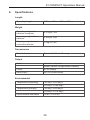
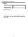
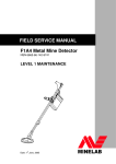
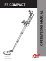
OPERATIONS MANUAL
F3 COMPACT
Revision 02
Part No: 4901-0103
WARNING
THIS DOCUMENT CONTAINS INTELLECTUAL PROPERTY,
TECHNICAL AND PROPRIETARY DATA AND INFORMATION
AND OTHER MATERIAL OWNED SOLELY BY MINELAB
ELECTRONICS PTY LIMITED. THIS MATERIAL MUST NOT
BE USED WITHOUT THE PRIOR WRITTEN PERMISSION OF
MINELAB ELECTRONICS PTY LTD.
© Minelab Electronics Pty Ltd. All Rights Reserved.
This document is protected by copyright. Apart from any use
permitted under the Australian Copyright Act 1968 (Cth) or other
applicable laws, any unauthorised use, appropriation or reproduction
of this document or any part of it is strictly prohibited. No part of
this document may be used or reproduced by any means or by
any process, in any form, without the prior written permission of
the copyright owner Minelab Electronics Pty Ltd of 118 Hayward
Avenue, Torrensville, SA 5031, Australia.
F3 COMPACT Operations Manual
Table of Contents
1. Introduction.......................................................................................3
2. General Description and Preparation..............................................5
2.1
2.2
2.3
Mine Detecting Set
F3 COMPACT Main Components
F3 COMPACT Preparation
5
6
8
3. Functional Description................................................................... 13
3.1
3.2
3.3
Functional Controls and Displays
13
3.1.1 On/Off Knob.................................................................. 13
3.1.2 Sensitivity Knob............................................................. 14
3.1.3 Ground Balance/Audio Reset Button ............................ 15
3.1.4 Noise Cancel Button . ................................................... 15
3.1.5 LED Display................................................................... 16
3.1.6 Battery Status................................................................ 17
3.1.7 Earset Socket................................................................ 17
Functional Tones
18
Test Piece – Functional Test
19
4. Operating Procedures.....................................................................21
4.1
4.2
4.3
4.4
Introduction
21
Standard Procedure
22
4.2.1 STEP 1 Switch ON........................................................22
4.2.2 STEP 2 Ground Balance...............................................23
4.2.3 STEP 3 Test Piece.........................................................24
Optional Procedures
26
4.3.1 Noise Cancel.................................................................26
4.3.2 Audio Reset...................................................................27
Sweeping Procedure
29
1
F3 COMPACT Operations Manual
4.5
4.6
4.7
4.8
Pinpointing Procedure
30
4.5.1 STEP 1 Mapping the Target...........................................30
4.5.2 STEP 2 Determine Centre of Target..............................32
Multiple Targets
33
4.6.1 STEP 1 Mapping the Target...........................................33
4.6.2 STEP 2 Determining the Centre of Target.....................34
Operating Multiple Detectors in Close Proximity
34
Completion of Operations
35
5. Care and Troubleshooting..............................................................37
5.1
5.2
Routine Care
Troubleshooting
37
38
6. Specifications..................................................................................39
2
F3 COMPACT Operations Manual
1.
Introduction
Since 1996, Minelab has designed, developed and manufactured its
range of detectors to meet the requirements of mine and unexploded
ordnance clearance operations throughout the world. Through
its patented and unique technology, Minelab has emphasised
equipment capability and operator safety in its products.
The F3 COMPACT is a lightweight, compact detector that includes
a uniquely designed mechanical platform thereby providing superior
ergonomics.
The F3 COMPACT incorporates patented bipolar technology that
enhances Minelab’s renowned and highly successful Multi-Period
Sensing (MPS) technology. Through MPS, the sensitivity of a
detector remains consistent regardless of the mineralised content
of soil. Bipolar technology also helps to eliminate the possibility of
initiating a magnetic influence mine. Combined with ‘static coupling’
the F3 COMPACT does not require motion to detect a target thereby
making pinpointing techniques fast and accurate.
Figure 1: F3 COMPACT mine detector
3
F3 COMPACT Operations Manual
The F3 COMPACT is a robust detector that is extremely simple
to operate. When working in an environment that includes highly
mineralised ground or electrical interference from overhead power
lines or other sources, simple and quick semi-automatic procedures
can be initiated by an operator resulting in the detector continuing to
perform at maximum capability.
The F3 COMPACT incorporates several safety features such as
Low Battery and System Fault warnings, audible confirmation at
the completion of specific operational procedures, and continuous
microprocessor controlled internal self-testing. The inclusion of a
Test Piece provides the operator with a quick and easy check to
ensure that the detector is working at its operational capability.
The F3 COMPACT also provides a visual indication of detection via
a Light Emitting Diode (LED) display. Sensitivity and volume settings
can be changed through seven preset selections. If required, the F3
COMPACT can be programmed to user initiated customised volume
and sensitivity selections using Minelab’s configuration software.
Components of the F3 COMPACT are manufactured within tightly
controlled parameters so that they can be interchanged in the field
without any requirement for calibration.
The F3 COMPACT is designed to satisfy MIL STD 810G.
NOTE
Although the F3 COMPACT can withstand immersion to a depth of
three metres for short periods of time, it is NOT designed for use as
an underwater detector.
4
F3 COMPACT Operations Manual
2.
General Description and Preparation
2.1 Mine Detecting Set
The F3 COMPACT is supplied as a mine detecting set (Figure 2)
comprising:
• Hard Case (optional) • Operations Manual
• Detector • Field Guide
• Soft Carry Bag • Test Piece
• Earset (Speaker On and
Speaker Off variants)
• Four C-Cell Batteries
(Alkaline or Rechargeable)
nds
12
seco
60cm )
(24”
1
io
Aud et
Res
15cm
(6”)
T
F3
PAC
ctor
COM
Dete
..
nds.
45
Mine
seco
-1
-0047
4903
2
3
60cm )
(24”
Figure 2: F3 COMPACT mine detecting set
The optional Hard Case permits the stowage of the detector inside
the Soft Carry Bag and provides protection for the detector when in
transit or placed in storage.
The Soft Carry Bag allows the operator to comfortably carry the
detector when use of the Hard Case is impractical. The Soft Carry
Bag is not suitable for use when transporting the detector by
road or air. For added protection during road or air transport, it is
recommended that the detector be packed in the Hard Case.
5
F3 COMPACT Operations Manual
2.2 F3 COMPACT Main Components
Figure 3 identifies the main components of the F3 COMPACT.
Armrest
Armrest Strap
Test Piece
Battery
Compartment
Handle
Assembly
Earset
Connector
Main Body
Shaft Hinge
Controls
Upper Camlock
Upper Shaft
Middle Shaft
Lower Camlock
Coil
Lower Shaft
Coil Pivot Assembly
Skid Plate
Figure 3: F3 COMPACT main components
Battery Compartment – contains 4 x C cell alkaline or
rechargeable batteries. A battery map is provided to indicate correct
alignment of batteries when inserted into the compartment.
Armrest and Strap – provided for operator comfort when the F3
COMPACT is used for prolonged periods. The Armrest can be
extended for operator comfort.
6
F3 COMPACT Operations Manual
Test Piece – conveniently stowed on the Armrest to allow the
operator to ensure the detector is working at its operational
capability.
Earset Connector – provides connection for the Earset and also
the programming cable when using the configuration software to
customise volume and sensitivity settings.
Main Body – waterproof housing containing the detector electronics
and batteries.
Handle Assembly – collapsible handle that also contains Ground
Balance/Audio Reset button, LED display, LED On/Off button, Noise
Cancel button and Battery Low LED indicator.
Controls – On/Off and Volume/Sensitivity selection knobs – both
controls cannot be accidentally rotated.
Shaft Hinge – pivot point for unfolding or folding the shafts. The
hinge is only locked in position when the Handle Assembly is in its
deployed position.
Upper, Middle, Lower Shafts – carbon fibre shafts that are
adjustable for operator comfort and for changes in demining
positions.
Upper and Lower Camlocks – self-cleaning locking mechanisms to
secure middle and lower shafts.
Coil Pivot Assembly – permits the tilt and rotation of the coil and
provides a tension screw for adjustment as required.
Coil – waterproof enclosed coil to eliminate possible interference
from vegetation; can be rotated 180 degrees. The mono loop design
ensures consistent sensitivity around the entire circumference, and
across the complete surface of the coil.
Skid Plate – removable disk that protects and prolongs the life of the
coil thereby reducing maintenance costs.
7
F3 COMPACT Operations Manual
2.3 F3 COMPACT Preparation
To prepare the detector for use, conduct the following procedure:
a. Open the Hard Case and/or Soft Carry Bag.
b. Remove the F3 COMPACT and inspect for obvious signs of
damage. If damage is evident, report to the supervisor/team
leader.
c. Unlock the Battery Compartment Lid by twisting the Battery
Lock Lever counter clockwise one-quarter turn. Once unlocked,
pull the lid away from the Battery Compartment (the lid will stay
attached by a tether as shown in Figure 4).
d. Using the battery map located on the side of the Main Body,
insert four C cell batteries. Taking care not to snag or trap the
tether, replace the Battery Compartment Lid and rotate the
Battery Lock Lever clockwise one-quarter turn. If the batteries are
inserted incorrectly, the F3 COMPACT will fail to function when
switched on.
e. Using Figure 5 as a guide, unfold and adjust the F3 COMPACT.
Figure 4: Removing the Battery Compartment Lid
NOTE
The F3 COMPACT requires 4 C cell batteries for operation. Use only
high quality alkaline or rechargeable batteries. Minelab recommends
that only rechargeable batteries with a capacity of 4000 mAH or
greater be used with the F3 COMPACT. Rechargeable batteries
have specific charge/discharge maintenance requirements, which
should be strictly followed to ensure maximum battery life.
8
F3 COMPACT Operations Manual
1
2
3
4
5
9
F3 COMPACT Operations Manual
6
7
8
A
B
Figure 5: Guide to unfolding and adjusting the F3 COMPACT
NOTE
When the Handle Assembly is locked into position (Frame 3), it will
also lock the Upper Shaft in position. To unlock the Handle Assembly
and to allow the Upper Shaft to rotate when repacking the detector,
gently but firmly impact the base of the palm against the top of the
handle behind the LED display.
f. Extend the Lower and Middle Shafts to suit the selected demining
position as shown in Figure 6.
10
F3 COMPACT Operations Manual
Figure 6: F3 COMPACT in the standing, kneeling or prone positions
g. Undo the dust caps from the Earset plug and Earset socket on the
detector. Gently hold the Earset by the rubber collar using thumb
and index finger, the raised double arrow should be uppermost
(see Figure 7). Align the plug with the Earset socket and firmly
slide the collar onto the socket.
Figure 7: Connecting the Earset
11
F3 COMPACT Operations Manual
NOTE
The Earset connector is waterproof and must be connected and
disconnected from the Earset socket by holding the rubber collar.
Do not attempt to connect or disconnect the Earset by pushing or
pulling on the strain relief or wire at the rear of the rubber collar.
The F3 COMPACT is now ready for use. Refer to Chapter 3 for
Functional Description, and Chapter 4 for Operating Procedures.
To repack the F3 COMPACT, this preparation procedure should be
reversed.
12
F3 COMPACT Operations Manual
3.
Functional Description
3.1 Functional Controls and Displays
For ease of use, all controls and displays for the F3 COMPACT are
located on the Handle Assembly and Main Body. Figure 8 illustrates
the location of all controls.
Ground Balance/
Audio Reset Button
Noise
Cancel
Button
LED
On/Off
Button
On/Off
Knob
Sensitivity
Knob
Earset
Socket
Figure 8: F3 COMPACT controls
3.1.1 On/Off Knob
To switch the F3 COMPACT on, gently pull up the On/Off Knob and
rotate clockwise. Once in the On position release the knob back to
the locked position (refer Figure 9).
When switched on, the F3 COMPACT completes a series of internal
start-up functions including initialisation of the microprocessor and
self-tests, which check internal power supplies, transmitter etc.
Internal diagnostics take approximately 12 seconds to complete,
during which the operator will hear a series of rising tones (known as
the Start-Up Tones).
13
F3 COMPACT Operations Manual
On completion of the Start-Up Tones the F3 COMPACT emits a low
steady tone known as the Threshold Tone, which confirms to the
operator that the F3 COMPACT is functioning correctly.
During operation, continuous internal self-testing continues and an
alarm tone is triggered on detection of any fault condition (refer to
section 3.2 for a description of the alarm tones).
To turn the F3 COMPACT off, pull up the On/Off Knob and rotate
counter-clockwise to the Off position. Release the switch back to the
locked position.
60cm
(24 in)
12 seconds
Figure 9: Switching on the detector
3.1.2 Sensitivity Knob
The F3 COMPACT can be operated using seven preset volume
and sensitivity settings. Position 4 is the default position and should
always be selected when switching on the detector and conducting
the Test Piece procedure (refer to section 4.2.3).
The Yellow Dot on the decal indicates the position that, when
selected, permits the detector to be customised for specific Volume
and Sensitivity selections. To customise the detector, Minelab
supplied configuration software and cables are required. The
detector is shipped with a factory preset for the Yellow Dot selection;
this makes the detector operate as if it was performing at a capability
greater than Position 4.
14
F3 COMPACT Operations Manual
* WARNING *
When detecting minimum metal mines or targets with low metal
signatures, the F3 COMPACT should not be used on a selection
lower than the default setting (Position 4). Where possible,
Free From Explosive targets should be buried at the required
detection depth. Sensitivity options (Positions 4 to 7) should
then be tested to determine the most suitable sensitivity to
ensure detection of the target.
3.1.3 Ground Balance/Audio Reset Button
Easily identifiable as the Green Button located on top of the Handle
Assembly, this dual action button carries out the following functions:
a. Ground Balance. A key feature of the F3 COMPACT is its ability
to detect metallic mines in all ground conditions. False alarms due
to mineralised (magnetic/lateritic) soils are automatically removed
through the Ground Balance procedure.
b. Audio Reset. On occasion, the Threshold Tone may become
louder than normal. Holding the coil stationary over a metallic
object or over mineralised ground for an extended period of time
may cause this. Also, if the detector is being used in the kneeling
position (shafts retracted), any movement of the coil relative to the
shaft may cause the Threshold Tone to increase. The Threshold
Tone can be returned to the normal volume level using the Audio
Reset procedure (refer to section 4.3.2).
3.1.4 Noise Cancel Button
Interference from electrical motors, lights, power lines and other
detectors can occasionally cause the Threshold Tone to vary in
pitch and volume. When this occurs, the ability of an operator to
distinguish targets may be degraded.
Using the Noise Cancel function, the operator can initiate an
automatic frequency scanning sequence, as a result the F3
COMPACT will select an operating frequency that minimises the
effects of interference.
15
F3 COMPACT Operations Manual
3.1.5 LED Display
/deep target
esponse
ge/shallow
t response
A display of nine red LEDs provides a visual indication of target size
and proximity. The display can be switched On and Off by pressing
the LED On/Off button.
When the LED display is switched on, a minimum, of one LED will
illuminate representing the Threshold Tone (see Figure 10).
Figure 10: LED Display with noNo
target
response
target
Threshold tone only
Other typical illuminations of the LED display, including Battery Low
Alarm LED are illustrated in Figure 11.
Test Piece Procedure
Test Piece Procedure
Up illuminated
to three LEDs illuminated
Up to three LEDs
No target
No Threshold
target tone
only
Threshold tone
only
Small/deep target
response
Medium target
response
Medium target
response
Large/shallow
target response
Low battery alarm
Figure 11: Typical LED responses
Low battery alarm
16
F3 COMPACT Operations Manual
NOTE
The LED display will always be off when the detector is first switched
on.
3.1.6 Battery Status
Provided that the LED display is switched on, battery status can be
checked at anytime by pressing and holding down the Noise Cancel
button and then pressing and immediately releasing the LED On/
Off button. Once completed the LED display will indicate the battery
status for a period of three seconds.
3.1.7 Earset Socket
The F3 COMPACT has an internal speaker located inside the Main
Body, however, it can also be fitted with an Earset via the Earset
Socket. The procedure for connecting the Earset is described in
section 2.3.g.
A standard humanitarian demining Earset (Earset Speaker On)
permits the F3 COMPACT’s internal speaker to continue to function
even when the Earset is connected.
For military countermine applications, an Earset that mutes the F3
COMPACT’s internal speaker when the Earset is connected is available
(Earset Speaker Off). The Earset Speaker Off is identified by a short
length of green tubing located at the rear of the Earset plug.
* WARNING *
Minelab strongly recommends that an operator always wears an
Earset when using the F3 COMPACT detector.
17
F3 COMPACT Operations Manual
3.2 Functional Tones
The F3 COMPACT emits tones that vary in pitch and volume to alert
the operator to targets, automatic detector functions or equipment
alarm conditions. The following table summarises the tones that an
F3 COMPACT can produce.
Tones
Event
Description
Start-Up
Internal diagnostic checks
when the F3 COMPACT is
switched on
Four or five rising tones
over 12 seconds.
Threshold
Signifies correct operation of
detector
Steady low volume
continuous tone.
Ground
Balance
Indicates successful
Ground Balance procedure
completed
One fast high pitched
double beep.
Target
Indicates metal target
detected
Increases volume
(compared to Threshold
Tone) and high or low pitch
depending on target metal
composition and depth.
Battery Low
Indicates batteries do not
have enough charge to
continue detection
High pitched fast
continuous oscillating tone
PLUS blinking Battery Low
LED provided the LED
display is switched on.
Equipment
Fault
Indicates failure of detector
component
Low pitched slow
oscillating tone (ee-aww,
ee-aww).
Coil Fault
Indicates coil not connected
or not receiving sufficient
current
Low pitched double tone
every five seconds.
Noise Cancel
Indicates Noise Cancel
procedure is occurring
Two single beeps followed
by 45 seconds of short
double beeps finishing with
four single beeps.
Default
Sensitivity
Selected
Confirms to operator that
Sensitivity knob is at Position
4 (Default) when the detector
is switched on or Position 4
is selected when the detector
is in use
Double high pitched beep.
18
F3 COMPACT Operations Manual
Tones
Event
Description
Default
Sensitivity Not
Selected
Indicates that the default
sensitivity is not selected
when detector is switched on
Single low pitched beep
if sensitivity lower than
default (Position 4) and
single high pitched beep
if sensitivity higher than
default.
Changing
Sensitivity
Indicates of increasing or
reducing sensitivity
When increasing sensitivity
a single high pitched
beep. When decreasing
sensitivity a single low
pitched beep.
Table 1: Functional tones
NOTE
Electronics within the F3 COMPACT ensure that its performance
remains consistent as the charge state of the batteries begins to
reduce. When the batteries can no longer supply the necessary
power to sustain correct performance of the detector, a Battery Low
Alarm will alert the operator.
* WARNING *
When Battery Low Alarm occurs the operator must immediately
STOP demining operations. The F3 COMPACT should be
switched off and new or recharged batteries inserted into the
Battery Compartment.
3.3 Test Piece – Functional Test
The F3 COMPACT is supplied with a Test Piece designed to confirm
that the detector is working to correct specifications. The sensitivity
of the detector should be checked with the Test Piece when the
Sensitivity Knob is at Position 4 (default). In some instances, a user
may prefer to use inert mines or targets as test pieces because they
represent the local threat. Minelab recommends that the detector
always be first tested with the supplied Test Piece before local test
pieces are used for testing.
19
F3 COMPACT Operations Manual
NOTE
When switched on, maximum sensitivity is available 30 seconds
after the Threshold Tone commences. Do not test the detector with
the Test Piece until 30 seconds after the Threshold Tone begins.
* WARNING *
The Test Piece functional test must be conducted with the
Sensitivity Knob set to Position 4 (Default) and should be
conducted whenever the detector is switched on to confirm
correct functionality of the detector.
NOTE
After switching on the detector, the LEDs will always be disabled
unless the LED On/Off button is pressed.
If an Earset Speaker OFF is connected to the detector, the LED
display will be automatically disabled for tactical reasons. However,
if required the LED display can be enabled by pressing the LED On/
Off button.
20
F3 COMPACT Operations Manual
4.
Operating Procedures
4.1 Introduction
The F3 COMPACT is designed to ensure that operation of the
detector is as simple as possible. Additionally, the F3 COMPACT is
extremely capable, robust and safe to use, eliminating the need for
lengthy training requirements. This chapter describes procedures
for safe and effective operation of the F3 COMPACT. Where these
procedures contravene local Standard Operating Procedures,
local procedures should take precedence provided that all Minelab
recommended safety procedures are followed.
Figure 12: F3 COMPACT detector
21
F3 COMPACT Operations Manual
4.2 Standard Procedure
Ground Balance/
Audio Reset Button
On/Off
Knob
Sensitivity
Knob
Earset
Socket
Figure 13: F3 COMPACT controls
After unpacking the F3 COMPACT and preparing it for use as
described in chapter 2, complete the following THREE step standard
procedure.
4.2.1 STEP 1 Switch ON
a. Hold the coil at least 600 mm (24 ins) from the ground, and away
from any metallic objects. Ensure Sensitivity is set to Position 4
(default) and then turn the detector on by lifting and rotating the
On/Off knob clockwise.
60cm
(24 in)
12 seconds
Figure 14: Switching on the detector
The F3 COMPACT will emit a series of four or five rising tones over
12 seconds (internal diagnostic checks occurring). At the completion
of the Start-Up Tones a low volume Threshold Tone will remain
audible.
22
F3 COMPACT Operations Manual
b. If the Threshold Tone is steady continue with STEP 2. If the
Threshold Tone is noisy or uneven when the coil is stationary,
perform a Noise Cancel (section 4.3.1).
c. If the Threshold Tone is steady but seems louder than normal
when the coil is away from the ground and metallic targets,
perform an Audio Reset (section 4.3.2).
4.2.2 STEP 2 Ground Balance
Ensure this procedure is carried out on ground free of metal and hold
the coil about 150 mm (6 ins) above the ground.
a. Press down and hold the Ground Balance button. Slowly lower
the coil directly to the ground then lift the coil up again 150 mm
(6 ins). Refer to Figure 15.
b. Continue to slowly lower and raise the coil until the ‘Ground
Balance OK’ tone is heard. (‘Ground Balance OK’ tone consists of
a short high-pitched double beep).
c. Release the Ground Balance button.
Beep
Beep
150mm
(6 in)
Figure 15: Ground Balance procedure
NOTES
Movement of the coil during the entire Ground Balance procedure
should be slow, continuous and smooth and each down and up
movement should take 3 to 4 seconds.
23
F3 COMPACT Operations Manual
If the Ground Balance OK tone is not heard within 20 seconds of
starting the procedure, release the Ground Balance button and
repeat this procedure. If there is metal in the ground under the coil
whilst Ground Balancing, the detector will not Ground Balance
correctly. Move the detector and repeat the Ground Balance over
ground that is free of metallic objects.
After the Ground Balance procedure is completed the detector will
automatically cancel interference from the ground under the coil. If
ground conditions change (changing mineralisation in the ground)
this procedure may need to be repeated.
For operator training purposes, once Ground Balance has been
successfully completed, the detector can be made to ‘forget’ the
Ground Balance conditions by pressing and holding the Ground
Balance button for five seconds. This will allow the operator
to practise the Ground Balance procedures against the same
mineralised ground.
4.2.3 STEP 3 Test Piece
Ensure the operator’s hands and arms are free of metallic objects
(watches, rings etc), and that no other metallic objects are near the coil.
a. Remove the Test Piece from its stowed position on the Armrest
by extending the Armrest and rotating the Test Piece clockwise.
Hold the Test Piece above the middle of the coil with the end
containing metal AWAY from the coil.
b. Move the Test Piece towards the centre of the coil until it lightly
touches the surface then move it sideways off the coil (the
Test Piece should be moved slowly and smoothly during this
procedure).
A faint but clear response (change in Threshold Tone volume and
pitch) should be heard indicating the sensitivity of the detector is
correct.
With the LED display enabled, the Test Piece Procedure will result in
the illumination of at least one additional LED
24
F3 COMPACT Operations Manual
NOTE
Maximum sensitivity is only available 30 seconds after the Threshold
Tone commences. Do not test the detector with the Test Piece until
30 seconds after the Threshold Tone begins. If the Test Piece cannot
be heard, conduct an Audio Reset and recheck. If the Test Piece
fails to be detected the detector must be considered faulty and must
not be used.
Figure 16: Test Piece procedure
NOTE
The Test Piece not only ensures that the sensitivity of the detector
is correct but also gives the operator an example of how a minimum
metal mine might sound when deeply buried; for example Type 72A
at 15 cm. (Sensitivity knob set to Position 4)
25
F3 COMPACT Operations Manual
4.3 Optional Procedures
If after Step ONE the Threshold Tone is not low and steady, conduct
one or both of the following procedures:
a. Noise Cancel (see 4.3.1)
b. Audio Reset (see 4.3.2)
4.3.1 Noise Cancel
If the Threshold Tone is noisy or uneven when the coil is stationary,
conduct Noise Cancel as follows:
a. Holding the coil stationary and at least 600 mm (24 ins) above
the ground press and immediately release the Noise Cancel
button. (see Figure 17)
Noise Cancel will commence with two single beeps followed by 45
seconds of sharp double beeps, finishing with four single beeps.
Figure 17: Noise Cancel
During the 45 seconds, the detector scans the environment
searching for any electrical interference. Once detected, the F3
COMPACT will automatically select a different operating frequency
to eliminate or reduce the interference.
26
F3 COMPACT Operations Manual
NOTE
The detector cannot be used for clearing operations during Noise
Cancel. The coil should not be moved during this procedure nor
should metallic objects be brought near the coil.
4.3.2 Audio Reset
Whenever the Threshold Tone sounds louder than normal perform
the Audio Reset procedure as follows:
a. Hold the coil away from any metallic objects. Press and
immediately release the Ground Balance button (green button
located on top of the handle).
Within two seconds the Threshold Tone will return to its correct level.
(see Figure 18).
Figure 18: Audio Reset
NOTES
The detector cannot be used for clearing operations during the Audio
Reset procedure.
If the Audio Reset button is held too long, the detector will
commence the Ground Balance procedure.
27
F3 COMPACT Operations Manual
STEP 1
SWITCH ON
60cm
60cm
(24 in)
(24 in)
1212seconds
seconds
Optional
Procedure
Threshold
Noisy/Uneven
YES
NOISE
CANCEL
YES
AUDIO
RESET
NO
Threshold
Louder than
Normal
NO
STEP 2
GROUND BALANCE
Beep
Beep
150mm
(6 in)
STEP 3
TEST PIECE
Figure 19: Standard and optional procedures
28
F3 COMPACT Operations Manual
Noise Cancel and Audio Reset procedures can be performed any
time the Threshold Tone becomes noisy, uneven or rises in volume.
Once Noise Cancel and/or Audio Reset are complete, continue
with Standard Procedure steps 2 and 3. Figure 19 illustrates this
sequence. Once completed, the F3 COMPACT can commence
operations in compliance with local Standard Operating Procedures.
Having completed STEPS 1, 2 and 3 the F3 COMPACT remembers
the Ground Balance setting even after the detector has been
switched off.
After Noise Cancel is completed the F3 COMPACT remembers the
frequency selected to minimise interference, even if the detector is
switched off.
4.4 Sweeping Procedure
The F3 COMPACT should be swept with a smooth even motion at a
speed of 0.6 m/s (2 ft/s). If the detector is swept too fast or too slow,
small or deep targets may be missed. The coil should always be kept
at the same height above the ground with care taken to ensure that
the coil is not inadvertently raised at the end of each sweep (see
Figure 20).
Direction of
Movement
Mine Lane
Figure 20: Sweeping procedure
29
F3 COMPACT Operations Manual
Depth of detection depends on target distance from the coil, not
depth of the target under the ground. Therefore, the coil should be
swept as close to the ground as possible to maximise detection
depth (local Standard Operating Procedures take precedence).
When a target is initially detected, an operator should stand in place
and continue to sweep the F3 COMPACT beyond the target in an
attempt to find clear ground. In doing so the operator will:
a. Immediately gain an impression of the size of the target prior to
commencing the pinpointing procedure; and
b. Confirm the target is not in close proximity to a second target
thereby avoiding a possible booby trap.
NOTE
Minelab recommends a half coil (100 mm/4 inches) overlap on
successive sweeps as an operator moves forward in a mine lane.
4.5 Pinpointing Procedure
The design of the F3 COMPACT makes pinpointing accurate and
fast. The F3 COMPACT’s mono loop coil means there are no gaps
in sensitivity around the coil’s circumference or across its surface.
Pinpointing is conducted by first mapping the target and then finding
its centre.
4.5.1 STEP 1 Mapping the Target
Having detected a target using the sweeping procedure and obtained
a rough idea of its size and location, the precise location of the
target can be ‘mapped’ using the F3 COMPACT’s ‘Edge Detection’
technique.
Edge detection makes use of the coil’s consistent sensitivity around
its circumference to detect the area of a target. To conduct edge
detection, the coil should approach the target location from a variety
of angles as shown in Figure 21.
As the coil approaches the target, the Threshold Tone will change
indicating that coil is in close proximity to the target.
30
F3 COMPACT Operations Manual
At the change of the Threshold Tone, the operator should mentally
mark the position on the ground, move the coil away, and approach
the target from another angle.
This process continues until the operator achieves a mental picture
of the target area.
Figure 21: Mapping the target
* WARNING *
Extreme care must be taken when mapping the target to ensure
that the coil does not touch the ground (or any exposed parts of
the mine) or snag on any previously undetected trip wires.
For large minimum metal anti-tank mines, it is possible that the
area mapped out may be less than the actual area of the mine.
After an initial detection, if the coil is repeatedly swept over
a small deeply buried target, the response may fade. If this
occurs, move the coil away from the target and perform an
Audio Reset procedure (section 4.3.b) then return to the target
location and continue with the pinpointing procedure.
31
F3 COMPACT Operations Manual
4.5.2 STEP 2 Determine Centre of Target
In Step 1, the area of a target was determined. If the metal in the
target is sufficiently small, the area mapped will also be small and
therefore it is a relatively simple matter to pinpoint the centre of the
target.
To determine the centre, for larger targets, the coil should be
slowly moved across the mapped area. As the coil approaches the
centre of the target, the threshold tone will increase to a maximum
volume (pitch may be high or low depending on the composition of
the metal). Where maximum volume is achieved, the coil can be
considered to be above the centre of the target.
Once confirmed, local Standard Operating Procedures should be
followed to mark the target.
Maximum Volume
Figure 22: Determine target centre
NOTE
An operator can confirm that the centre of a target has been
located by moving the coil slightly in any direction, and returning
to the centre. In doing so the volume of the Threshold Tone should
decrease from maximum, as the coil leaves the centre, and return to
maximum as the coil returns to the centre.
32
F3 COMPACT Operations Manual
4.6 Multiple Targets
There may be occasions when an operator will encounter multiple
targets. For example, small anti-personnel mines may be laid in
a cluster, or a large anti-tank mine may be surrounded by smaller
anti-personnel mines or booby-traps. Regardless, the pinpointing
procedure for the F3 COMPACT can be used to effectively map a
suspicious area.
4.6.1 STEP 1 Mapping the Target
Using the procedure described in section 4.5.1, an area enclosing
the multiple targets can be mapped.
Figure 23: Mapping multiple targets
NOTE
To an experienced operator the shape of the mapped area can
indicate whether multiple targets may be present.
33
F3 COMPACT Operations Manual
4.6.2 STEP 2 Determining the Centre of Target
The pitch of the Threshold Tone will rise or fall depending on the
combination of metals or the composition of metal in a mine. This
means that, in some instances, experienced operators may be able
to identify one mine against another (see Figure 24).
By slowly moving the coil across the mapped area, it may be
possible to detect tonal differences indicating multiple targets.
* WARNING *
The volume from a large target may mask that
of a small target if the small target is located very
close to the large target.
Figure 24: Multiple targets
4.7 Operating Multiple Detectors in Close Proximity
On occasion it may be necessary to operate F3 COMPACT
detectors in close proximity. In normal circumstances, an F3
COMPACT detector can operate as close as two metres (seven
feet) to another without suffering
excessive mutual interference. To
Maximum Volume
achieve this minimum operating distance between detectors, Noise
Cancel must be conducted as follows:
a. With all other detectors switched off, switch on the first detector
and perform Noise Cancel as described in section 4.3.1.
34
F3 COMPACT Operations Manual
b. Once Noise Cancel is finished on the first detector, leave it
switched on. Ensure that the second detector is at least two
metres away and switch it on. Conduct Noise Cancel using the
Noise Cancel button of the second detector.
c. Continue this process for all detectors being used in close
proximity.
Noise Cancel
2 metres
Figure 25: Operating detectors in close proximity
4.8 Completion of Operations
At the completion of operations, the F3 COMPACT should be
checked with the Test Piece before switching off to ensure
satisfactory performance before being packed away. Once
completed:
a. Turn the detector off.
b. Clean the detector and inspect for any signs of damage.
c. Remove the batteries from the Battery Compartment and stow in
Soft Carry Bag.
35
F3 COMPACT Operations Manual
d. Disconnect the Earset.
e. Retract the Middle and Lower Shafts rotating the coil to the
stowed position.
f. Collapse Handle and pivot the retracted shafts securing in
position with the Armrest Strap.
g. Stow the detector in the Soft Carry Bag and Hard Case if
available.
h. Check all components are accounted for (especially the Test
Piece and Earset) and are correctly packed.
36
F3 COMPACT Operations Manual
5.
Care and Troubleshooting
5.1 Routine Care
The F3 COMPACT is designed for lasting use in harsh operating
environments, however, proper care and maintenance will ensure
long-term reliability. Key to ensuring the durability of the F3
COMPACT is the correct stowage of the detector whenever it is not
in use. Additionally, operators of F3 COMPACT detectors should be
aware of the following:
a. During rest periods, wherever possible, the detector should be
sheltered from direct sun, rain, snow etc.
b. On completion of operations, with the F3 COMPACT fully
extended, all shafts should be wiped with a damp cloth to remove
any dirt or dust before collapsing the shafts.
c. Do not use solvents to clean the F3 COMPACT. If any part of the
detector comes into contact with corrosive substances (including
salt water), wash the detector with clean fresh water and dry with
a clean cloth.
d. Ensure the F3 COMPACT is dry before stowing in the Soft Carry
Bag.
e. Ensure the batteries are removed from the Battery Compartment
before stowing the detector.
f. The Skid Plate is designed to protect the coil and may require
replacement after long periods of use. There is no requirement
to remove the Skid Plate to clean the inside during routine
maintenance. To replace the Skid Plate, remove the original using
fingers to lever it from the coil, then push the replacement Skid
Plate onto the coil (see Figure 26).
Figure 26: Replacing the Skid Plate
37
F3 COMPACT Operations Manual
5.2 Troubleshooting
Table 2 provides several troubleshooting procedures in response to
a variety of possible problems.
Problem
Recommended Procedure
F3 COMPACT will not switch 1. Check batteries have been inserted
on
correctly into the Battery Compartment, or
2. Replace batteries.
After switching on there is a
very loud noise
1. Conduct Audio Reset
After switching on the
Threshold Tone varies in
pitch and volume with the
coil stationary
1. Conduct Noise Cancel
2. Move away from noise source
There is no sound from the
Earset
1. Disconnect and reconnect the Earset, or
2. Try a known serviceable Earset (if this
solves the problem, the original Earset may
be faulty, if this does not solve the problem,
the Earset socket may be faulty)
There is no sound from the
Speaker
1. Switch off and on, or
2. Disconnect Earset, Switch off and on
Cannot hear the Test Piece.
1. Ensure that the detector has been turned
on for at least 30 seconds.
2. Ensure the sensitivity of the detector is set
at Position 4.
3. Conduct Audio Reset
Table 2: Troubleshooting
38
F3 COMPACT Operations Manual
6.
Specifications
Length
Operating Length
1490 mm/59 ins – 950 mm/37 ins
Weight
Operating weight with
batteries (complete)
2.57 kg/5.7 lbs
Operating weight without
batteries
2.40 kg/5.3 lbs
Shipping weight (in hard
case with batteries)
7.4 kg/16.3 lbs
Transmission
Pulse Induction
Bipolar Multi-Period Sensing
Output
Audio
Internal Loudspeaker
Earset (various configurations available)
Visual
9 LED Display
Data Output
RS-232 (bidirectional)
Environmental
Temperature (Operating)
-30 deg C to 60 deg C
-22 deg F to 140 deg F
Temperature (Storage)
-30 deg C to 80 deg C
-22 deg F to 176 deg F
Environmental Endurance
To MIL STD 810G
39
F3 COMPACT Operations Manual
Batteries
Alkaline
4 x C cell LR14
Rechargeable
4 x NiCad or NiMh C cell minimum 4000 mAh
capacity
Battery Reverse Polarity
Protection
Yes
Patents and Trademarks
Patents and trademarks may apply to this product.
Patents: www.minelab.com/patentmarking
Disclaimer
As a world leader in metal sensing technology, Minelab strives to
continually improve its product range. Minelab reserves the right to
introduce changes to the design, technical features and accessories
of this product.
40
Contact Details:
Minelab Electronics Pty Ltd
tel: +61 8 8238 0888
Minelab Americas Inc
tel: +1 630 401 8150
Minelab International Limited
tel: +353 21 423 2352
email: [email protected]
www.minelab.com