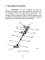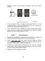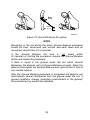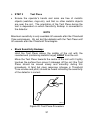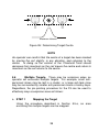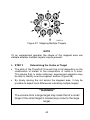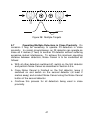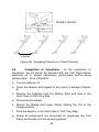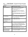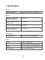
1
! "# $ %& WARNING THIS DOCUMENT CONTAINS MINELAB ELECTRONICS PTY LIMITED RIGHTS TECHNICAL DATA OR RESTRICTED RIGHTS DATA OR BOTH. Minelab Electronics This work is copyright. Apart from any use as permitted under the Copyright Act 1968, no part may be reproduced by any process without written permission from Minelab Electronics Pty Ltd 118 Hayward Avenue, Torrensville, SA 5031 Australia 1 TABLE OF CONTENTS 1. Introduction ................................................................................... 4 2. General Description and Preparation........................................... 6 2.1 Mine Detecting Set .................................................................... 6 2.2 F3 Main Components ................................................................ 8 2.3 F3 Preparation........................................................................... 9 2.4 Use of Battery Pack Bag and Extension Cable ........................ 14 2.5 Changing Endcaps .................................................................. 15 3. Functional Description................................................................ 16 3.1 Functional Controls.................................................................. 16 3.2 Sensitivity Endcaps ................................................................. 18 3.3 Functional Tones ..................................................................... 19 3.4 Test Piece - Functional Test .................................................... 21 4. F3L Configuration........................................................................ 22 4.1 Introduction.............................................................................. 22 4.2 Description .............................................................................. 22 4.3 Operation-Volume/Sensitivity Control ...................................... 23 4.4 Operation-LED Display ............................................................ 24 5. Operating Procedures................................................................. 27 5.1 Introduction.............................................................................. 27 5.2 Standard Procedure ................................................................ 28 5.3 Optional Procedure.................................................................. 32 5.4 Sweeping Procedure ............................................................... 36 5.5 Pin-Pointing Procedure............................................................ 37 5.6 Multiple Targets....................................................................... 39 5.7 Operating Multiple Detectors in Close Proximity ...................... 41 2 5.8 Completion of Operations ........................................................ 42 6. Care and Trouble Shooting......................................................... 43 6.1 Routine Care ........................................................................... 43 6.2 Trouble Shooting ..................................................................... 44 7. Specifications .............................................................................. 46 3 1. Introduction 1.1 Since 1996, Minelab has designed, developed and manufactured its range of detectors to meet the requirements of mine and explosive ordnance clearance operations throughout the world. Through its patented and unique technology, Minelab has emphasised equipment capability and operator safety in its products. 1.2 The F3 mine detector incorporates patented Bi-polar technology that enhances Minelab’s renowned and highly successful Multi-Period-Sensing (MPS) technology. Through MPS, the sensitivity of a detector remains consistent regardless of the mineralised content of soil. Additionally, Bi-polar technology assists in eliminating the possibility of initiating a magnetic influence mine. Combined with “static coupling” the F3 does not require motion to detect a target thereby making pin-pointing techniques fast and accurate. P0631-A Figure 1: F3 Mine detector 4 1.3 The F3 is a robust detector that is extremely simple to operate. There are no complicated controls resulting in the operator being able to focus on the vital task of mine detection. If mine detection occurs in a “difficult” environment that includes highly mineralised ground or electrical interference from over head power lines or other sources, simple and quick semi-automatic procedures can be initiated by an operator to allow the detector to continue performing at maximum capability. 1.4 The F3 incorporates several safety features such as Low Battery and Fault warnings, audible confirmation at the completion of specific operational procedures, and continuous microprocessor controlled internal self-testing. The inclusion of a Test Piece provides an operator with a quick and easy test to ensure the detector is working to its operational capability. 1.5 The F3 can be supplied with an optional Light Emitting Diode (LED) display and Volume/Sensitivity Control. In this configuration, the detector is known as the F3L. 1.6 Components of the F3 are manufactured within tightly controlled parameters so that they can be interchanged in the field without any requirement for calibration. 1.7 The F3 is designed to satisfy MIL STD 810F: Method 512.4 Water Immersion (IP67) Method 514.5 Vibration Method 516.5 Shock NOTE Although the F3 can withstand immersion to a depth of 3m for short periods of time, it is NOT designed for use as an underwater detector. 5 2. General Description and Preparation 2.1 Mine Detecting Set. The F3 is supplied as a mine detecting set (Figure 2) comprising: • Hard Case • Test Piece • Detector • Operations Manual • Soft Carry Bag • Field Guide • Earset • Red Endcap (Low Sensitivity) • Four D-Cell Batteries (Alkaline or Rechargeable) • Battery Pack Bag and Battery Pack Extension Cable (optional) Figure 2: F3 Mine Detecting Set 6 a. As illustrated in Figure 2, the Hard Case includes an insert for easy placement of the F3 and accessories. The case also provides protection for the detector and it is recommended that the F3 be secured in its Hard Case whenever it is not in use or during transit. Failure to transport the detector in the supplied Hard Case may void warranty. b. A Soft Carry Bag is supplied to allow an operator to comfortably carry the detector when use of the Hard Case is impractical (e.g. when walking through rough terrain). The Soft Carry Bag is not designed to transport the detector by road or air. The detector must be packed in the Hard Case during road or air transport. Figure 3 illustrates the position of the F3 inside the Soft Carry Bag. Figure 3: F3 Packed in the Soft Carry Bag 7 2.2 F3 Main Components. Figure 4 identifies the main components of the F3 which comprise: Armrest Strap Endcap Armrest Upper Shaft Electronics Pack Handle Battery Pack Middle Shaft Upper Camlock Lower Shaft Middle Camlock Coil Lower Camlock P0635-A Skidplate Figure 4: F3 – Main Components a. Sensitivity Endcap – the sensitivity of the F3 can be changed by using either the Black (maximum) or Red (minimum) Endcaps. b. Armrest Strap – provided for operator comfort when the F3 is used for prolonged periods. c. Armrest – adjustable (via a camlock) to maximise comfort of use for an operator. 8 d. Electronics Pack – contains the electronics of the F3 and is permanently fixed to the detector. e. Upper Shaft – made of aluminium for increased robustness and provides mounting for the Handle, Battery Pack, Electronics Pack and Armrest. f. Battery Pack – removable to reduce the weight of the F3 for periods of prolonged use – contains four D cell batteries. g. Handle – ergonomically designed for operator comfort and includes Earset connector and F3 controls. h. Middle Shaft – made of aluminium for robustness and adjustable for operator comfort or for changes in demining positions. i. Lower Shaft – made of impact resistant carbon fibre and is adjustable. j. Lower, Middle and Upper Camlocks – self-cleaning locking mechanisms to position the coil, lower and middle shafts. k. Coil – enclosed waterproof coil to eliminate possible interference from vegetation – can be rotated 180 degrees – a monoloop design that ensures consistent sensitivity around the entire circumference of the coil and across the complete surface of the coil. l. Skid Plate – removable plastic disk that protects and prolongs the life of the coil thereby reducing maintenance costs. 2.3 F3 Preparation. To prepare the detector for use, conduct the following procedure: a. Open the Hard Case or Soft Carry Bag. b. Remove the F3 and inspect for obvious signs of damage. c. Check that the correct Sensitivity Endcap is selected and fitted correctly (if not, exchange Endcaps as described at Section 2.5). d. Hold the F3 in an inverted position with the Endcap resting against the inside of the Hard Case (or Soft Carry Bag). 9 e. Unlock the Battery Pack Lid by twisting the Battery Lock Lever counter clockwise one-quarter turn. Once unlocked, pull the lid away from the Battery Pack (the lid will stay attached to the Battery Pack by a tether – Figure 5). Battery Pack Battery Lock Lever Battery Pack Lid Battery Map P0615-A Figure 5: Removing the Battery Pack Lid f. Using the battery maps, located on the side of the Battery Pack and on the inside of the Battery Pack Lid, insert four D cell batteries. Replace the Battery Pack Lid and rotate the Battery Lock Lever clockwise one-quarter turn. If the batteries are inserted incorrectly, the F3 will fail to function when switched on. NOTE The F3 requires 4 D cell batteries for operation. Use only high quality alkaline (LR20) or rechargeable batteries. Minelab recommends that only rechargeable batteries with a capacity of 4000 mAH or greater be used with the F3. Rechargeable batteries have specific charge/discharge maintenance requirements, which should be strictly followed to ensure maximum battery life. Only NiCad and NiMh type D cell rechargeable batteries are suitable for use with the F3. 10 g. Extend the Lower and Middle Shafts to suit the selected demining position as shown in Figure 6. For use in the standing position: P0619-A P0618-A P0620-A Figure 6: F3 in the Standing, Kneeling or Prone Positions • Open the Lower Camlock and rotate the coil to the desired position. The normal operating position of the coil is in line with the shaft. However, the coil can also be positioned at right angles to either side of the shaft (required if the F3 is to be used in the prone position). Once the position of the coil is selected, lock it into position by closing the Lower Camlock. 11 Middle Camlock Upper Camlock Lower Camlock P0617-A Figure 7: Camlock Locations • Holding the detector with the coil pointing toward the ground, open the Middle Camlock and extend the Lower Shaft to the desired length. Lock the Lower Shaft into position by closing the Middle Camlock. NOTE The Lower Shaft must be extended at least 100mm (4ins). Incorrect operation of the detector may result if the detector is used with the Lower Shaft fully retracted. • Open the Upper Camlock and extend the Middle Shaft to the desired length. Lock the Middle Shaft into position by closing the Upper Camlock. h. Undo the dustcaps from the Earset plug and Earset socket on the detector. As shown in Figure 8, gently hold the Earset by the rubber collar using thumb and index finger (raised double arrow should be uppermost). Align the plug with the Earset socket and firmly slide the collar onto the socket. Confirm the plug is locked into position by gently pulling back on the rubber collar. 12 P0638-B Figure 8: Fitting the Earset NOTE The Earset connector is waterproof and it is most important that it is connected and disconnected from the Earset socket by holding the rubber collar. Do not attempt to connect or disconnect the Earset by pushing or pulling on the strain relief or wire at the rear of the rubber collar. i. For operator comfort, adjust the Armrest by opening the Armrest Camlock and then slide the Armrest to the desired position. Lock the Armrest Camlock and tighten the Armstrap as required. j. The F3 is now ready for use. Refer to Chapter 3 for Functional Description and Chapter 5 for Operating Procedures. k. To repack the F3, the procedure described above should be reversed. NOTE Batteries can be inserted and removed from the Battery Pack while attached to the Upper Shaft as described at Section 2.3.e. Alternatively, the Battery Pack can be removed from the Upper Shaft by pulling down the Lock Lever located between the Battery Pack and the Electronics Pack as shown in Figure 9. 13 Upper Shaft Battery Pack Electronics Pack Lock Lever P0616-A Figure 9: Battery Pack Removal To refit the Battery Pack, ensure that the Lock Lever at the front of the Electronics Pack is in the unlocked position and position the Battery Pack on the rail underneath the Upper Shaft. Slowly slide the Battery Pack towards the Electronics Pack until the connector is firmly engaged. Secure the Battery Pack by rotating the Lock Lever in a clockwise motion into the locked position. 2.4 Use of Battery Pack Bag and Extension Cable. If required, the Battery Pack can be separated from the Upper Shaft thereby reducing the overall weight of the detector. Using the bayonet connectors at each end of the Extension Cable, connect the cable to the Battery Pack and feed the cable through the base of the Battery Pack Bag before connecting to the Electronics Pack. The Battery Pack Bag can then be clipped onto a belt worn by the operator as shown in Figure 10. P0653-A Figure 10: Battery Pack Separated from Upper Shaft 14 2.5 Changing Endcaps. The F3 can be used with Black or Red Sensitivity Endcaps. The decision on which Endcap to use will be provided by the local authority. To fit a Sensitivity Endcap: a. Ensure the F3 is switched off. b. Place the thumb of one hand in the centre of the Endcap and curl the fingers under the base of the Endcap. c. Gently push inwards with the thumb and simultaneously pull the base of the Endcap away from the Electronics Pack (Figure 11). d. Exchange or replace the Endcap by gently positioning the inside of the base of the Endcap under the base of the Electronics Pack. Using the palm of the hand, apply light pressure to fit the Endcap into position. P0651-A P0650-A Figure 11: Removing a Sensitivity Endcap **WARNING** The Sensitivity Endcap also provides impact protection to the Electronics Pack. Whenever an Endcap has been removed from the Electronics Pack never place the base of the detector against the ground or sharp objects. 15 3. Functional Description 3.1 Functional Controls. For ease of use, all controls for the F3 are located on the Handle. For information on the additional controls included in the F3L configuration, refer to Chapter 4. Figure 12 illustrates the location of all controls: Ground Balance/ Audio Reset Button Noise Cancel Button On/Off Switch Earset Socket P0621-A Figure 12: F3 Controls a. On/Off Switch. • The F3 is switched on by sliding the On/Off Switch toward the Handle. When switched on, the F3 completes a series of internal start-up functions including initialisation of the microprocessor and self-tests which check internal power supplies, transmitter etc. • These internal diagnostics take approximately 12 seconds to complete during which the operator will hear a series of rising tones (known as the Start-Up Tones). • At the completion of the Start-Up Tones the F3 emits a low steady tone known as the Threshold Tone, which confirms to the operator that the F3 is functioning correctly. 16 • During operation, continuous internal self-testing continues and an alarm tone is triggered on detection of any fault condition (refer to Section 3.3 for a description of the alarm tones). • To turn the F3 off, slide the On/Off Switch away from the Handle. b. Ground Balance/Audio Reset Button. Easily identifiable as the Green Button located on top of the Handle, this dual action button carries out the following functions: • Ground Balance. A key feature of the F3 is its ability to detect metallic mines in all ground conditions. False alarms due to mineralised (magnetic/lateritic) soils are automatically removed through use of the Ground Balance function. • Audio Reset. On occasion, the Threshold Tone may become louder than normal. Holding the coil stationary over a metallic object or over mineralised ground for an extended period of time may cause this. Also, if the detector is being used in the kneeling position (shafts retracted), any movement of the coil relative to the shaft may cause the Threshold Tone to increase. The Threshold Tone can be returned to the normal volume level using the Audio Reset function. c. Noise Cancel Button. • Interference from electrical motors, lights, power lines and other detectors can occasionally cause the Threshold Tone to vary in pitch and volume. When this occurs, the ability of an operator to distinguish targets may be degraded. • Using the Noise Cancel function, an operator can initiate an automatic frequency scanning sequence resulting in the F3 selecting an operating frequency that minimises the effect from interference. d. Earset Socket. • The F3 has an internal speaker located inside the Handle. However, the F3 can also be fitted with an Earset via the Earset Socket. The procedure for connecting the Earset is described at Section 2.3.h. 17 • A standard humanitarian demining Earset (Earset Speaker On) permits the F3’s internal speaker to continue to function even when the Earset is connected. • For military countermine applications, an Earset that mutes the F3’s internal speaker when the Earset is connected is available (Earset Speaker Off). The Earset Speaker Off is identified by a short length of green tubing located at the rear of the Earset plug. **WARNING** Minelab strongly recommends that an operator should always wear an Earset when using the F3 detector. 3.2 Sensitivity Endcaps. A unique feature of the F3 is its ability to change sensitivity through the exchange of Sensitivity Endcaps. This design feature eliminates the possibility of an operator selecting the wrong sensitivity through manipulation of knobs or switches. The Sensitivity Endcap provides an obvious visual cue that confirms the level of sensitivity selected in the F3. The F3 is supplied with Black and Red Sensitivity Endcaps. • Black Sensitivity Endcap. With the Black Sensitivity Endcap fitted, the F3 performs at maximum sensitivity. The Black Endcap MUST be selected when searching for minimum metal mines or when maximum clearance depth is required. • Red Sensitivity Endcap. With the Red Sensitivity Endcap fitted, the F3 performs at reduced sensitivity. This feature may be useful when there is a need to ignore small metal fragmentation on the surface but still detect large targets at depth. NOTE If the Red Sensitivity Endcap is not fitted correctly, or there is no endcap fitted, the detector automatically defaults to the maximum sensitivity setting (Black Sensitivity Endcap). If the Red Sensitivity 18 Endcap is partially dislodged or removed during use, an alarm tone will sound. **WARNING** Where a minimum metal mine threat exists, the F3 MUST be operated with the Black Sensitivity Endcap. Depending on the size of the target and the depth of detection required, the Red Sensitivity Endcap may not be suitable for use. It is recommended that, prior to operational use, the capability of the F3, fitted with the Red Sensitivity Cap, be tested against the local threat to ensure detection occurs. 3.3 Functional Tones. The F3 emits tones that vary in pitch and volume to alert an operator to targets, automatic detector functions or equipment alarm conditions. The following table summarises the tones that an F3 can produce: Tones Event Description Start-Up Internal checks when the F3 is switched on Four rising tones over 12 seconds Threshold Signifies correct operation of detector Steady low volume continuous tone Ground Balance Indicates successful Ground Balance procedure completed One fast high pitched double beep Target Indicates metal target detected Increases volume (compared to Threshold Tone) and high or low pitch 19 depending on target metal composition and depth Low Battery Indicates batteries do not have enough charge to continue detection High pitched fast continuous oscillating tone Equipment Fault Indicates failure of detector component or a dislodged Red Sensitivity Endcap Low pitched slow oscillating tone (eeaww, ee-aww) Coil Fault Indicates coil not connected or not receiving sufficient current Low pitched double tone every five seconds Noise Cancel Indicates Noise Cancel procedure is occurring Two single beeps followed by 45 seconds of short double beeps finishing with four single beeps NOTE Circuitry within the F3 ensures that its performance remains consistent as the charge state of the batteries begins to reduce. When the batteries can no longer supply the necessary power to sustain correct performance of the detector, a Low Battery Alarm will alert the operator. **WARNING** When Low Battery Alarm occurs the operator must immediately STOP demining operations. The F3 should be switched off and new or recharged batteries inserted into the Battery Pack (Refer to Section 2.3.e for instruction on changing batteries). 20 3.4 Test Piece – Functional Test. The F3 is supplied with a Test Piece specially designed to confirm that the detector is working to correct specifications. The sensitivity of the detector should be checked with the Test Piece before, during and after demining operations, (in compliance with local Standard Operating Procedures). In some instances, a user may prefer to use inert mines as test pieces because they represent the local threat. Minelab recommends that the detector always be first tested with the supplied Test Piece before local test pieces are used for testing. NOTE When switched on, maximum sensitivity is available 30 seconds after the Threshold Tone commences. Do not test the detector with the Test Piece until 30 seconds after the Threshold Tone begins. 21 4. F3L Configuration 4.1 Introduction. Detectors fitted with the LED Display and Volume/Sensitivity (V/S) Control leave the factory with the LED Display and Volume/Sensitivity Control enabled. The LEDs give an operator a visual indication of the size and proximity of a target. The V/S Control provides the facility to reduce or increase V/S levels to suit specific detection circumstances. If required, the LED display and the ability to vary V/S levels can be disabled on the F3L. 4.2 Description. The F3L is fitted with a modified speaker pod comprising (Figure 13): • 13 red LED display to display target strength and proximity • Volume/Sensitivity increase button decrease button . • Red “Battery Low” alarm LED. • Quick guide to enable and disable all LEDs. • Quick guide to enable and disable V/S control buttons. Target Strength LEDs (13 total) and Volume/Sensitivity Target Strength LEDs (13 total) Quick guide to enable and disable LED Display “Battery Low” Alarm LED Quick Guide to enable and disable Volume/Sensitivity Control buttons Volume/Sensitivity Control buttons Figure 13: F3L Speaker Pod 22 4.3 Operation-Volume/Sensitivity Control. From the default (middle) V/S setting, it is possible to increase or decrease V/S levels in five steps. Regardless of the V/S level selected, the volume of the Threshold Tone will remain the same. For safety reasons, the V/S setting will always commence at the default (middle) setting every time the F3L is switched on. The Test Piece Procedure must ALWAYS be carried out at the default V/S level setting. **WARNING** Decreasing the Volume/Sensitivity of the F3 detector also decreases the sensitivity (depth of detection) of the detector, thereby increasing the possibility of missing minimum metal mines. a. Increasing Volume/Sensitivity. To increase the V/S level, press and release the Volume/Sensitivity button the required number of times (maximum five times from default level). During each button press, a short high-pitched tone will be heard. When the maximum V/S level is reached a long high-pitched tone will be heard. b. Decreasing Volume/Sensitivity. To decrease the V/S level, button the required press and release the Volume/Sensitivity number of times (maximum five times from default level). During each button press, a short low-pitched tone will be heard. When the minimum V/S level is reached a long low-pitched tone will be heard. c. Resetting Volume/Sensitivity to Default Setting. Where the V/S setting has been adjusted, it can be restored to default level by: • pressing and releasing the double tone is heard, • pressing and holding the button and then simultaneously quickly pressing and releasing the black Noise Cancel Button, or or 23 buttons as required until a • switching the F3L off and on. d. Disabling and Enabling Volume/Sensitivity Control. The F3L factory pre-set is V/S Control enabled but this feature can be disabled or enabled as follows: • Disable. To disable the V/S Control after the detector has been button and simultaneously, switched on, press and hold the quickly press and release the black Noise Cancel Button. If done correctly, a double tone will be heard. • Enable. To enable the V/S Control after the detector has been switched on, press and hold the button and simultaneously, quickly press and release the black Noise Cancel Button. If done correctly, a double tone will be heard. NOTE If the or buttons are pressed and the V/S Control has been disabled, then a double tone will be heard signifying that adjustment of the V/S has been disabled and the F3L is operating at the default V/S setting. If the V/S control has been disabled, it will remain disabled regardless of switching the F3L Off and On. It will remain disabled until the V/S Control is enabled. 4.4 Operation-LED Display. The LED display is located on top of the speaker pod and comprises 13 red LEDs, which provide an indication of target size and proximity. Additionally, a “Battery Low” alarm red LED will commence flashing (along with the Battery Alarm tone) when battery power is not sufficient to maintain consistent equipment sensitivity. Typical illuminations are illustrated in Figure 14: No target Threshold Tone only 24 NOTE If more than one LED is illuminated or the display is erratic (in combination with a variable tone response), conduct Audio Reset and/or Noise Cancel. Test Piece Procedure at V/S default setting with Black Endcap Up to three LEDs illuminated Small/deep target response Medium target response Large/shallow target response Low Battery Alarm Figure 14: Typical LED Responses 25 a. Disabling and Enabling LED Display. The F3L factory pre-set is LED display enabled but this feature can be disabled or enabled as follows: • Disable. With the detector switched on, to disable the LED button and simultaneously, quickly display, press and hold the press and release the green Ground Balance button. NOTE Once the LED display is disabled, unless subsequently enabled, the LEDs will remain extinguished even if the detector is repeatedly switched off and on. • Enable. With the detector switched ON, to enable the LED display, press and hold the button and simultaneously, quickly press and release the green Ground Balance button. NOTE Once the LED display is enabled, unless subsequently disabled, the LEDs will be illuminated whenever the detector is switched on. If an Earset Speaker OFF is connected to the detector, the LED display will be automatically disabled for tactical reasons. However, if required the LED display can be enabled as described above. 26 5. Operating Procedures 5.1 Introduction. The F3 is designed to ensure that operation of the detector is as simple as possible. Additionally, the F3 is extremely capable, safe to use, robust and eliminates the need for complicated controls or lengthy training requirements. This Chapter describes procedures for safe and effective operation of the F3. Where these procedures contravene local Standard Operating Procedures, local procedures should take precedence provided all Minelab recommended safety procedures are followed. Armrest Strap Endcap Armrest Upper Shaft Electronics Pack Handle Battery Pack Middle Shaft Upper Camlock Lower Shaft Middle Camlock Coil Lower Camlock P0635-A Skidplate Figure 15: F3 Detector 27 5.2 Standard Procedure. After unpacking the F3 and preparing it for use as described in Chapter 2 (appropriate Sensitivity Endcap fitted as directed by the local authority), complete the THREE step standard procedure as follows: Ground Balance/ Audio Reset Button Noise Cancel Button On/Off Switch Earset Socket P0621-A Figure 16: F3 Controls a. STEP 1 • Switch ON Hold the coil at least 600mm (24ins) from the ground and away from any metallic objects. Turn the detector on by sliding the On/Off switch back towards the handle. P0645-A Figure 17: Switching on the Detector • The F3 will emit a series of four rising tones over 12 seconds (internal diagnostic checks occurring). At the completion of the 28 Start-Up Tones a low volume Threshold Tone will remain audible. Figure 18: Switch On • If the Threshold Tone is steady continue with STEP 2. If the Threshold Tone is noisy or uneven when the coil is stationary, perform a Noise Cancel (Section 5.3.a). • If the Threshold Tone is steady but seems louder than normal when the coil is away from the ground and metallic targets, perform an Audio Reset (Section 5.3.b). b. STEP 2 Ground Balance • Ensure this procedure is carried out on ground free of metal and hold the coil about 150mm (6 ins) above the ground. • Press down and hold the green Ground Balance button and slowly lower the coil directly to the ground then lift the coil up again 150mm (6ins). Refer to Figure 19. • Continue to slowly lower and raise the coil until the ‘Ground Balance OK’ tone is heard. (‘Ground Balance OK’ tone consists of a short high-pitched double beep). • Release the Ground Balance button. 29 Beep Beep 150mm (6 in) P0623-A Figure 19: Ground Balance Procedure NOTE Movement of the coil during the entire Ground Balance procedure should be slow, continuous and smooth and each down and up movement should take 3 to 4 seconds. If the Ground Balance OK tone is not heard within 30 seconds of starting the procedure, release the Ground Balance button and repeat this procedure. If there is metal in the ground under the coil whilst Ground Balancing, the detector will not Ground Balance correctly. Move the detector and repeat the Ground Balance over ground that is free of any metallic objects. After the Ground Balance procedure is completed the detector will automatically cancel interference from the ground under the coil. If ground conditions change (changing mineralisation in the ground) this procedure may need to be repeated. 30 c. STEP 3 • Test Piece Ensure the operator’s hands and arms are free of metallic objects (watches, rings etc), and that no other metallic objects are near the coil. The orientation of the Test Piece during the test is dependent on which Sensitivity Endcap is connected to the detector. NOTE Maximum sensitivity is only available 30 seconds after the Threshold Tone commences. Do not test the detector with the Test Piece until 30 seconds after the Threshold Tone begins. • Black Sensitivity Endcap: Hold the Test Piece above the middle of the coil with the rounded end (containing metallic target) AWAY from the coil. Move the Test Piece towards the centre of the coil until it lightly touches the surface then move it sideways off the coil (the Test Piece should be moved slowly and smoothly during this procedure). A faint but clear response (change in Threshold Tone volume and pitch) should be heard indicating the sensitivity of the detector is correct. P0647-A Figure 20: Test Piece Procedure 31 • Red Sensitivity Endcap: Hold the Test Piece above the middle of the coil with the rounded end (containing the metallic target) TOWARDS the coil. Move the Test Piece towards the centre of the coil until it lightly touches the surface then move it sideways off the coil (the Test Piece should be moved slowly and smoothly during this procedure). A clear response (change in Threshold Tone volume and pitch) should be heard indicating the sensitivity of the detector is correct. NOTE The Test Piece not only ensures the sensitivity of the detector is correct but also gives the operator an example of how a minimum metal mine might sound when deeply buried: for example Type 72A at 15cm . (Black Endcap only). 5.3 Optional Procedure. If after Step ONE the Threshold Tone is not low and steady, conduct one or both of the following: a. Noise Cancel. If the Threshold Tone is noisy or uneven when the coil is stationary, conduct Noise Cancel as follows: NOTE The detector cannot be used for clearing operations during Noise Cancel. The coil should not be moved during this procedure nor should metallic objects be brought near the coil during this procedure. • Holding the coil stationary and at least 600mm (24ins) above the ground press and immediately release the Noise Cancel button (Black Button located behind the handle). 32 P0649-A Figure 21: Noise cancel • Noise Cancel will commence with two single beeps followed by 45 seconds of sharp double beeps finishing with four single beeps. • During the 45 seconds, the detector scans the environment searching for any electrical interference. Once detected, the F3 will automatically select a different operating frequency to eliminate or reduce the interference. b. Audio Reset. Whenever the Threshold Tone sounds louder than normal perform the Audio Reset procedure as follows: NOTE The detector cannot be used for clearing operations during the Audio Reset procedure. • Audio Reset should be carried out whenever the threshold volume seems louder than normal. • Hold the coil away from any metallic objects. Press and immediately release the Ground Balance button (Green Button located on top of the Handle). Within two seconds the threshold tone will return to its correct level. 33 P0646-A Figure 22. Audio Reset NOTE If the Audio Reset button is held too long, the detector will commence the Ground Balance procedure. Noise Cancel and Audio Reset procedures can be performed at any time the Threshold Tone becomes noisy, uneven, or rises in volume. Once Noise Cancel or Audio Reset is complete, continue with steps 2 and 3. Figure 23 illustrates this sequence. Once completed, the F3 can commence operations in compliance with local Standard Operating Procedures. Having completed STEPS 1, 2 and 3 the F3 remembers the Ground Balance setting even after the detector has been switched off. After Noise Cancel is completed the F3 remembers the frequency selected to minimise interference, even if the detector is switched off. 34 STEP 1 SWITCH ON Optional Procedure Threshold Noisy/Uneven Y NOISE CANCEL N Threshold Louder than Normal Y AUDIO RESET N STEP 2 GROUND BALANCE STEP 3 TEST PIECE Figure 23: Standard & Optional Procedure 35 5.4 Sweeping Procedure. The F3 should be swept with a smooth even motion at a speed of 0.6 m/s (2 ft/s). If the detector is swept too fast or too slow, small or deep targets may be missed. The coil should always be kept at the same height above the ground with care taken to ensure that the coil is not inadvertently raised at the end of each sweep (Figure 24). Direction of Movement Mine Lane P0655-A P0624-A Figure 24: Sweeping Procedure a. Depth of detection depends on target distance from the coil, not depth of the target under the ground. Therefore, the coil should be swept as close to the ground as possible to maximise detection depth. (Local Standard Operating Procedures take precedence.) NOTE Minelab recommends a half coil (100mm / 4ins) overlap on successive sweeps as an operator moves forward in a mine lane b. When a target is initially detected, an operator should stand in place and continue to sweep the F3 beyond the target in an attempt to find clear ground. In doing so the operator will: • immediately gain an impression of the size of the target prior to commencing the pin-pointing procedure; and 36 • confirm the target is not in close proximity to a second target thereby avoiding a possible booby trap. 5.5 Pin-Pointing Procedure. The design of the F3 makes pinpointing accurate and fast. The F3’s monoloop coil means there are no gaps in sensitivity around the coil’s circumference or across its surface. Pin-Pointing is conducted as follows: a. STEP 1 Mapping the Target • Having detected a target and obtained a rough idea as to its size and location using the sweeping procedure, the precise location of the target can be “mapped” using the F3’s “Edge Detection” technique. • Edge Detection makes use of the coil’s consistent sensitivity around its circumference to detect the area of a target. To conduct edge detection, the coil should approach the target location from a variety of angles as shown in Figure 25. • As the coil approaches the target, the Threshold Tone will change indicating the coil is in close proximity to the target. At the change of the Threshold Tone, the operator should mentally mark the position on the ground, move the coil away, and approach the target from another angle. • This process continues until the operator achieves a mental picture of the target area. Figure 25: Mapping the Target 37 **WARNING** Extreme care must be taken when mapping the target to ensure that the coil does not touch the ground (or any exposed parts of the mine) or snag on any previously undetected trip wires. For large minimum metal anti-tank mines, it is possible that the area mapped out may be less than the actual area of the mine. After an initial detection, if the coil is repeatedly swept over a small deeply buried target, the response may fade. If this occurs, move the coil away from the target and perform an Audio Reset procedure (Section 5.3.b) then return to the target location and continue with the pin-pointing procedure. b. STEP 2 Determine Centre of Target • In Step 1, the area of a target was determined. If the metal in the target is sufficiently small, the area mapped will also be small and therefore it is a relatively simple matter to pin-point the centre of the target. • For larger targets, to determine the centre, the coil should be slowly moved across the mapped area. As the coil approaches the centre of the target, the threshold tone will increase to a maximum volume (pitch may be high or low depending on the composition of the metal). Where maximum volume is achieved, the coil can be considered to be above the centre of the target. • Once confirmed, local Standard Operating Procedures should be followed to mark the target. 38 Maximum Volume Figure 26: Determining Target Centre NOTE An operator can confirm that the centre of a target has been located by moving the coil slightly, in any direction, and returning to the centre. In doing so the volume of the Threshold Tone should decrease from maximum as the coil leaves the centre and return to maximum as the coil returns to the centre. 5.6 Multiple Targets. There may be occasions when an operator will encounter multiple targets. For example, small antipersonnel mines may be laid in a cluster, or a large anti-tank mine may be surrounded by smaller anti-personnel mines or booby-traps. Regardless, the pin-pointing procedure for the F3 can be used to effectively map a suspicious area as follows: a. STEP 1 Mapping the Target Using the procedure described in Section 5.5.a, an area enclosing the multiple targets can be mapped. 39 P0627-A Figure 27: Mapping Multiple Targets NOTE To an experienced operator the shape of the mapped area can indicate whether multiple targets may be present. b. STEP 2 Determining the Centre of Target • The pitch of the Threshold Tone will rise or fall depending on the combination of metals or the composition of metal in a mine. This means that, in some instances, experienced operators may be able to identify one mine against another (Figure 28). • By slowly moving the coil across the mapped area, it may be possible to detect tonal differences indicating multiple targets. **WARNING** The volume from a large target may mask that of a small target if the small target is located very close to the large target. 40 + Figure 28: Multiple Targets 5.7 Operating Multiple Detectors in Close Proximity. On occasion it may be necessary to operate F3 detectors in close proximity. In normal circumstances, an F3 detector can operate as close as 2 metres (7 feet) to another F3 detector without suffering excessive mutual interference. To achieve this minimum operating distance between detectors, Noise Cancel is to be conducted as follows: a. With all other detectors switched off, switch on the first detector and perform Noise Cancel as described in Section 5.3.a. b. Once Noise Cancel is finished on the first detector, leave it switched on and switch on the second detector (at least 2 metres away) and conduct Noise Cancel using the Noise Cancel button of the second detector. c. Continue this process for all detectors being used in close proximity. 41 NOISE CANCEL 2 metres Figure 29: Operating Detectors in Close Proximity 5.8 Completion of Operations. At the completion of operations, the F3 should be checked with the Test Piece before switching off to ensure satisfactory performance before being packed away. Once completed: a. Turn the detector off. b. Clean the detector and inspect for any signs of damage (Chapter 6). c. Remove the batteries from the Battery Pack and stow in the Hard Case or Soft Carry Bag. d. Disconnect the Earset. e. Retract the Middle and Lower Shafts rotating the Coil to the stowed position. f. Stow the detector in the Hard Case or Soft Carry Bag. g. Check all components are accounted for (especially the Test Piece and Earset) and are correctly packed. 42 6. Care and Trouble Shooting 6.1 Routine Care. The F3 is designed for lasting use in harsh operating environments. However, proper care and maintenance will ensure long-term reliability. Key to ensuring the survivability of the F3 is the correct stowage of the detector into its Hard Case whenever the detector is not in use. Additionally, operators of F3 detectors should be aware of the following: a. During rest periods, wherever possible, the detector should be sheltered from direct sun, rain, snow etc. b. At the completion of operations, with the F3 fully extended, all shafts should be wiped with a damp cloth to remove any dirt or dust before collapsing the shafts. c. Do not use solvents to clean the F3. If any part of the detector comes into contact with corrosive substances (including salt water), wash the detector with clean fresh water and dry with a clean cloth. d. Ensure the F3 is dry before stowing in the hard case. e. Ensure the batteries are removed from the Battery Pack before stowing the detector. f. The Skid Plate is designed to protect the coil and may require replacement after long periods of use. There is no requirement to remove the skid plate to clean the inside during routine maintenance. To replace the Skid Plate, remove the original using fingers to lever it from the coil. It is then a simple matter to push the replacement Skid Plate onto the coil. P0654-A Figure 30: Replacing the Skid Plate 43 6.2 Trouble Shooting. The following table provides several trouble shooting procedures in response to a variety of possible problems: Problem Recommended Procedure F3 will not switch On 1. Check batteries have been inserted correctly into the Battery Pack - or 2. Replace batteries - or 3. Remove Battery Pack and reconnect ensuring battery Lock Lever is locked into position - or 4. Exchange Battery Packs (if this solves the problem, the original Battery Pack may be faulty) After switching On there is a very loud noise 1. Ensure Lower Shaft is extended at least 100mm (4ins) beyond the Middle Shaft - or 2. Conduct Audio Reset After switching On the Threshold Tone varies in pitch and volume with the coil stationary 1. Conduct Noise Cancel There is no sound from the Earset 1. Disconnect and reconnect the Earset - or 2. Try a known serviceable Earset (if this solves the problem, the original Earset may be faulty, if this does not solve the problem, the Earset socket may be faulty) There is no sound from the Speaker 1. Switch Off and On - or Cannot hear the Test Piece with the Black Sensitivity End Cap 1. Ensure that the detector has been turned on for at least 30 seconds. 2. Disconnect Earset, Switch Off and On 44 Cannot hear the Test Piece with the Red Sensitivity End Cap 1. Repeat the Test Piece test and make sure the metal in the Test Piece is pointed toward the coil surface 45 7. Specifications Length: Operating Length 1500mm/59.4ins to 750mm/30ins Weight: Operating weight with batteries (complete) 3.2kg/7lbs Operating weight without Battery Pack 2.3kg/5lbs Battery Pack with batteries 0.9kg/2lbs Shipping weight (in hard case with batteries) 10.5kg/23lbs Transmission: Pulse Induction Bi-polar Multi-Period-Sensing Output: Audio Internal Loudspeaker Earset (various configurations avail) Visual 13 LED Display (F3L Configuration) Data Output RS-232 (bi-directional) 46 Environmental: Temperature (Operating) -30 deg C to 60 deg C -22 deg F to 140 deg F Temperature (Storage) -30 deg C to 80 deg C -22deg F to 176 deg F Environmental Resistance To MIL STD 810F: Method 512.4 (Water immersion IP67) Method 514.5 (Vibration) Method 516.5 (Shock) Batteries (4 required): Alkaline D cell LR20 Rechargeable NiCad or NiMh D cell minimum 4000mAh capacity Battery Reverse Polarity Protection: Yes Patents: Covered by International patents including: US4890064, US4894618, AUS595835, CAN1260146, AU7944001, AU7943901, AU7937601, GB2372329, AU2002951084, AU2002951089, US2002053908, US2002053907 and US2002050822 (some pending). Disclaimer As a world leader in metal sensing technology, Minelab strives to continually improve its product range. Minelab reserves the right to introduce changes to the design, technical features and accessories of this product. 47 Contact Details: Minelab Electronics Pty Ltd PO Box 537 Torrensville Plaza South Australia 5031 AUSTRALIA email: [email protected] tel: +61 88238 0888 Minelab USA 871 Grier Drive, Suite B-1 Las Vegas, Nevada 89119 UNITED STATES OF AMERICA email: [email protected] tel: +1 702 891 8809 Minelab International Limited Laragh, Bandon Co. Cork IRELAND email: [email protected] tel: +353 23 52101 www.minelab.com 48