1
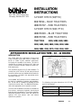
Buhler Versatile Inc.
Box 7300, 1260 Clarence Ave
Winnipeg, Manitoba R3C 4E8
INSTALLATION
INSTRUCTIONS
3-POINT HITCH (W/PTO)
86070394 -- BLUE TRACTORS
#86070707 -- RED TRACTORS
3-POINT HITCH (W/O PTO)
#86070393 -- BLUE TRACTORS
#86070706 -- RED TRACTORS
TRACTORS
9280, 9480, 9680, 9880
9282, 9482, 9682, 9882, 9184, 9384, 9484
9684, 9884, 2240, 2270, 2310, 2360, 2425
APPROXIMATE INSTALLATION TIME - 10 - 12 HOURS
INTRODUCTION
The 3-Point Hitch Kit is designed to mount on all
Buhler Versatile Large 4WD tractors. It allows the
tractor to utilize 3-point attached implements,
increasing the versatility of the tractor. The hitch is
classified as a Category IV Narrow (CAT IVN), but
can be converted to accept Category III Wide (CAT
IIIW) implements.
This procedure assumes a CAT IVN installation. To
convert from a CAT IVN to CAT IIIW, the top link and
lower links will be reversed. Additional information for
the conversion is located in the appropriate tractor
Operator’s Manual.
Once installed, the 3-point hitch can be controlled from
the cab by a combination of switches and potentiometers. The lift rate is controlled by adjusting the flow
control at the remote valve. For additional information,
refer to the appropriate tractor Operator’s manual.
The text of the installation instructions is divided into
four sections; mechanical, hydraulic, electrical and
final adjustment installations. The text also identifies
differences between tractors with and without an
optional PTO and tractors with and without
HydraFlow hydraulics.
19992765
1
The following chart gives dimensions for CAT IIIW
and CAT IVN hitches:
Category
IIIW and IVN
Upper link pin diameter
45 mm (1.75 in.)
Lift link pin diameter
51 mm (2.00 in.)
Width at hitch point
919 mm (36.18 in.)
89002215
1/02
\
KIT CONTENTS
PART #
V55505
86002558
86011250
V55488
V18160
V18161
V55539
V55540
V70091
V70092
N/A
9703812
86000321
86002569
V18171
V55507
V55635
V55637
V55640
V55922
V63954
V100198
V55644
86512787
9673063
9673064
86000623
86000624
86002133
86002561
86002564
86002693
86050318
86015981
V2747
V33451
V93021
9673037
9701029
9706434
9824331
9848710
86000538
86002423
86002448
86002452
V57212
V57213
QTY
W/PTO
QTY
W/O PTO
1
2
2
N/A
1
1
1
2
1
1
1
2
1
2
2
6
2
1
2
2
3
2
2
2
2
1
1
1
1
1
6
2
1
1
5
12
1
1
1
1
4
2
2
1
1
1
1
1
N/A
N/A
N/A
1
1
1
1
2
1
1
1
2
1
2
2
6
2
1
2
2
3
2
2
2
2
1
1
1
1
1
6
2
1
1
5
12
1
1
1
1
4
2
2
1
1
1
1
1
DESCRIPTION
WHERE USED
Top link bracket assembly
Top link spacer
3 point hitch mounting bracket
Upper Mounting bracket
Right side sway block
Left side sway block
Upper link
Lift link
Lift bracket assembly
Lift bracket assembly
Rockshaft Assembly
Hydraulic cylinder
Drawbar cage
Lower link
Lower cylinder pin
Shims
Lower pin
Top pin
Upper pin
Plate
Stud
Hydraulic hose
Link Pin
Groove Pin
Hydraulic hose
Hose assembly (100R)
End cover
Hose (560)
Valve
Bracket
Shim 1/4″
Pin
Hydraulic hose
Hydraulic hose
Bundle strap
Tie strap
Valve seal kit
Indicator light
Controller
3-point hitch wire harness
Spring retainer
Knob
Rocker switch
Lowering rate potentiometer
Command potentiometer
Current controller
Upper link decal
Upper link decal
Section 1, step 17
Section 1, step 17
Section 1, step 16
Section 1, step 15
Section 1, step 30
Section 1 step 28
Section 1, step 36
Section 1, step 31, 35
Section 1, step 7
Section 1, step7
Section 1, step 9
Section 1, step 22, 27
Section 1, step 19
Section 1, step 32, 35
Section 1, step 23, 27
Section 4
Section 1, step 34, 35
Section 1, step 36
Section 1, step 24, 27
Section 1, step 33, 35
Section 2, step 8, 9
Section 2, step 36
Section 1, step 32, 35
Section 1, step 32, 35
Section 2, step 33
Section 2, step 31
Section 2, step 13
Section 2, step 30
Section 2, step 12
Section 1, step 37
Section 4
Section 1, step 31, 35
Section 2, step 29
Section 2, step 26
As needed
As needed
Section 2, step 11
Section 3 step 8
Section 3, step 2
Section 3, step 12
Section 3, step 9
Section 3, step 9
Section 3, step 3, 5
Section 3, step 7
Section 3, step 6
Section 3, step 1
Section 1, step 39
Section 1, step 39
2
PART #
V57214
V57215
V57216
9706934
9706935
V15673
V18173
V18790
V19104
V22913
V30944
V55661
V55957
V56007
V70253
70783
76352
80680
84384
128996
216773
247780
270184
280744
9628503
9702507
9804255
86002556
V44253
V50133
88557
86503612
86512499
V12862
88725
374890
9846950
9847024
86516994
382101
86599641
QTY
W/PTO
QTY
W/O PTO
2
2
1
1
1
1
4
2
6
2
2
2
1
1
1
2
2
6
1
2
1
4
4
4
6
1
4
2
8
8
6
18
42
2
4
34
8
8
4
N/A
1
2
2
1
1
1
1
4
2
6
2
2
2
1
1
1
2
2
6
1
2
1
4
4
4
6
1
4
2
N/A
N/A
N/A
20
54
2
4
34
8
8
4
12
1
DESCRIPTION
WHERE USED
Category decal
Category decal
Implement decal
Switch plate
3 point hitch decal
Connector
Cylinder spacer
Cotter pin
Slotted spring pin
90_ elbow
Flange screw 1/2″
Spacer
Snapper pin
Upper bushing
Hydraulic union tee
Cap screw M
90_ elbow (37D-NP)
Lock washer
Hydraulic adapter
Union tee (37D)
90_ elbow (37D-OR)
Flange nut
Klik pin 1/4″
Carriage bolt .38 x 2.00
Nut
Connector 3/4″
Flange screw M6
Lower bushing
Washer
Cap screw
Cap screw .75 x 2.00
Hard washer M20
Flange nut M20
Washer
Cap screw
Cap screw M20 x 60
Cap screw M20 x 90
Nut M20
Washer
Cap screw M20 x 80
Installation instructions
Section 1, step 40, 41
Section 1, step 40, 41
Section 1, step 42
Section 3, step 4
Section 3, step 4
Section 2, step 22
Section 1, step 24, 27
Section 1, step 37
Section 1, step 23, 26, 27
Section 2, step 19, 20
Section 1, step 33, 35
Section 1, step 32, 35
Section 1, step 36
Section 4
Section 2, step 14
Section 1, step 31, 35
Section 2, step 18, 20
Section 2, step 8, 9, 13
Section 2, step 23
Section 2, step 32, 35
Section 2, step 24
Section 4
Section 1, step 34, 35
Section 4
Section 2, step 8, 9, 13
Section 2, step 25
Section 3, step 1, 2
Section 4
Section 1, step 18
Section 1, step 18
Section 1, step 16
Section 1, step 9, 16, 17, 28, 30
Section 1, step 7, 8, 9, 15, 19
Section 1, step 34, 35
Section 1, step 28, 30
Section 1, step 7, 8, 19
Section 1, step 9
Section 1, step 12, 13
Section 1, 31
Section 1, step 15
NOTE: If the 3PT Hitch Kit is being installed on a
9282 or 9184 model tractor, order additional tee
fitting 86014503 (section 2, step 14).
NOTE: If the 3PT Hitch Kit is being installed on an 80
series non Hi Flo tractor, order additional connector
fitting 139398 (Section 2, step15).
3
\
SPECIAL TOOLS
There are no special tools required to install the
3-Point Hitch on the Buhler Versatile 4WD tractors.
TRACTOR PREPARATION
1. Park the tractor on a clean level surface, set the
parking brake and remove the keys from the
ignition.
2. Install the articulation lock and chock the front
wheels of the tractor.
3. Disconnect the battery cables as detailed in
Section 3 - Electrical of the service manual.
4. Properly support the rear axle of the tractor and
using a suitable lifting devise remove the rear
wheels. Retain the hardware for reinstallation.
5. Remove the seat, 1, from the cab as detailed in
Section 11 - Cab of the Buhler Versatile 4WD
service manual.
1
2
6. Remove the right hand side console lower panel,
1, as detailed in Section 11 – Cab of the Buhler
Versatile 4WD service manual.
1
3
4
\
7. Remove the rear cab shield, 1, as detailed in
Section 11 - Cab of the Buhler Versatile 4WD
service manual.
1
4
8. Remove the rear access panel, 1, from the right
rear corner of the cab as detailed in Section 11 Cab of the Buhler Versatile 4WD service manual.
1
5
9. Remove the shield, 1, for implement valve
assembly by removing the four cap screws and
nuts, 2. Retain the hardware for reassembly.
1
2
6
5
\
SECTION 1
MECHANICAL COMPONENT
INSTALLATION
1. Using a suitable jack, support the drawbar and
remove the two cap screws and washers, 1, for
the drawbar clevis, 2, and the cap screw and
washer, 3, for the bridge plate, 4. Remove the two
klik pins, 5, and the stanchion pins, 6, from the
bridge plate. Remove the bridge plate and clevis
from the drawbar. Allow the drawbar to hang
downward off of the drawbar cage.
4
5
1
2
6
3
30000612
7
2. Remove the tractor drawbar cage, 1, by
removing five of the six rear bolts, 2, and the two
front bolts, 3. Loosen the other rear bolt but do
not remove it at this time.
2
3
1
30000613
8
3. Align a lifting devise to the drawbar cage, 1, and
remove the bolt, 2, loosened in Step 2. Allow the
draw bar cage to rest on the lifting device and pull
the cage away from the tractor.
2
NOTE: The drawbar cage is a very tight fit to the
tractor. Pull the cage straight back and away from the
tractor.
1
The drawbar cage can be discarded at this time.
30000614
9
6
\
4. Remove the two cap screws and flange nuts, 1,
for the hydraulic coupler bracket, 2. Discard the
hardware at this time.
2
1
1
30000615
10
5. If the tractor is equipped with an optional PTO,
disconnect the lube line, 1, from the PTO drop
box. Cap the elbow fitting for the lube line.
6. Fold the hydraulic coupler support bracket and
PTO lube line back and secure it to the
implement valve.
1
30000616
11
7. Using a proper lifting devise, align the left and
right hand side lower link brackets, 1, to the rear
frame of the tractor. Secure the lower link
brackets with six M20 x 60 cap screws and M20
serrated flange nuts, 2, in the front of the bracket.
Torque the hardware to 576 N⋅m (425 ft. lbs.).
2
30000617
1
12
7
\
8. Secure the rear of each lower link bracket, 1, with
five M20 x 60 cap screws and M20 serrated flange
nuts, 2. Torque the hardware to 576 N⋅m (425 ft.
lbs.).
2
1
30000618
13
9. Using a proper lifting devise align the rockshaft
assembly, 1, to the rear frame of the tractor.
Secure the rockshaft with eight M20 x 90 cap
screws, M20 hardened washers and M20 flange
nuts, 2.
1
2
NOTE: The rockshaft assembly weighs approximately 227 Kgs (500 lbs.). Use caution when
installing the rockshaft to the rear frame of the tractor.
2
10. Insert the cap screws and hardened washers
from the underside of the rear frame.
NOTE: The rockshaft is installed properly when the
feedback potentiometer is on the right hand side of
the tractor.
30000619
14
11. Torque the flange nuts to 576 N⋅m (425 ft. lbs.).
12. Install M20 jam nuts, 1, to six of the cap screws.
Do not install jam nuts to the two lower outside
cap screws, 2.
2
1
1
2
20000639
15
8
\
13. Install the hydraulic coupler bracket to the two
lower outside cap screws and install the
remaining two jam nuts, 2, on top of the coupler
bracket. Torque all eight jam nuts to 576 N⋅m
(425 ft. lbs.).
1
2
2
30000621
16
14. If the tractor is equipped with the optional PTO,
remove the cap from the lube line and the elbow
fitting and connect the lube line, 1, to the drop box
elbow. Tighten the fitting securely.
1
30000616
17
15. If the tractor is not equipped with the optional
PTO, use an appropriate lifting device and install
the upper link bracket, 1. Secure the bracket to
the rear frame of the tractor with twelve M 20 x 80
cap screws, 2, and M20 flange nuts. Torque the
hardware to 460 N⋅m (340 ft. lbs.).
1
For tractors not equipped with an optional PTO,
skip step #15, 16, 17, and 18 and proceed to step
#19.
2
2
2
18
9
\
16. For tractors equipped with an optional PTO, install
the upper link left and right hand side mounting
brackets, 1, to the to the rear frame of the tractor
with three 3/4 - 10 UNC x 2.0 cap screws and flat
washers. The cap screws and washers are
installed from the underside of the tractor. Torque
the hardware to 460 N⋅m (340 ft. lbs.).
1
1
30000623
19
17. Align the upper link face bracket, 1, to the side
mounting brackets and install a shim, 2, between
the face and side mounting brackets.
2
1
30000624
20
18. Install eight 5/8 - 11 UNC x 2.5 cap screws and
flat washers, 1. Torque the hardware to 174 N⋅m
(128 ft. lbs.).
1
1
30000625
21
10
\
19. Using a proper lifting device, align the drawbar
cage, 1, to the rear frame of the tractor and
secure it with twelve M20 x 60 cap screws and
M20 flange nuts, 2. When the cage is aligned
properly, move the lifting device away from the
tractor. Torque the hardware to 960 N⋅m (706 ft.
lbs.).
NOTE: The drawbar cage weighs approximately 230
Kgs. (510 lbs.). Use caution when installing cage to
the rear frame of the tractor.
2
1
30000626
22
20. Using a floor jack align the drawbar, 1, to the
cage, 2, and install the bridge plate, 3. Install the
cap screw and washer, 4, to secure the bridge
plate to the drawbar and torque it 960 N⋅m (706
ft. lbs.). Install the stanchion pins, 5, and install
the klik pins, 6, to secure the drawbar.
3
6
4
1
5
20000627
2
23
21. Install the drawbar clevis, 1, and secure with two
cap screws and washers, 2. Torque the hardware
to 960 N⋅m (706 ft. lbs.).
2
1
20000628
24
11
\
22. Install the barrel end of the left hand side lift
cylinder, 1, into the bottom of the drawbar cage,
2. Make certain that the ports of the cylinder face
rearward.
1
23. Secure the barrel end of the lift cylinder by
installing a pin, 3, (55640) from the outside of the
tractor to the inside of the drawbar cage. Secure
the roll pin with two spring pins, 4, at either end.
3
4
2
20000629
25
24. Attach the rod end of the cylinder, 1, to the lift
arm, 2, using the headed pin and spacers. The
spacers, 3, go on either side of the spherical
bearing in the end of the cylinder rod.
2
25. Be certain that the grease zerk in the end of the
rod is facing rear ward before the pin is installed.
To install the pin it will be necessary to move the
lift arm above the coupler bracket. Align the
cylinder rod end with the hole in the lift arm and
install a temporary pin. Be certain the shipping
caps are remove from the lift cylinder and raise
the lift arm and cylinder rod above the coupler
bracket.
3
1
20000630
26
26. Tap the headed pin, 1, through the lift arm,
spacer, cylinder, spacers and lift arm and secure
the outside of the headed pin with a roll pin, 2.
2
27. Repeat steps 22 through 25 for the right hand
side lift cylinder.
1
20000631
27
12
\
28. Install the left hand side sway block, 1, to the
outside of the drawbar cage, 2. Secure the sway
block with two 3/4 - 10 UNC x 1 3/4 cap screws
and hardened flat washers, 3. Torque the
hardware to 270 N⋅m (200 ft. lbs.).
29. For additional information on the sway block
positioning, refer to the appropriate tractor
Operator’s Manual.
3
30. Repeat step 28 for the right hand side sway
block.
1
2
20000632
28
31. Align the right hand side lift link, 1, to the
rockshaft arm, 2, and align two spacers, 3,
between the lift arm and the rod end of the link.
Secure the lift link with the upper lift link pin, 4.
The pin must be installed from the inside of the
rockshaft arm outward. Secure the pin with an
M10 x 25 shoulder bolt, 5. Torque the hardware
to 54 N⋅m (40 ft. lbs.).
5
2
4
3
1
20000633
29
32. Install the lower link, 1, to the drawbar cage, 2,
with a spacer, 3, to the inside of the lower link.
Install the lower lift link pin, 4, through the lift link,
spacer and drawbar cage.
NOTE: The lower link weighs approximately 50 Kgs
(110 lbs.). Use caution when installing onto the
tractor.
3
2
4
1
20000634
30
13
\
33. When the lower link and pin is aligned properly,
secure it to the lower link bracket with a plate, 1,
and a 1/2 -13 UNC x 1.00 flange screw, 2. Tighten
the hardware securely.
2
1
20000635
31
34. Attach the lower end of the lift link, 1, to the lower
link by installing a pin, 2. Install a washer, 3, on
the inside of the pin and secure it with a klik pin,
4. Make certain that the float slot in the link faces
the front of the tractor and the pin is positioned in
the rear hole of the lower link.
3
1
4
35. Repeat steps 31 through 34 for the left hand side
lift link and lower link.
20000636
2
32
36. Install the upper link, 1, to the bracket, 2, with the
narrow end of the upper link going through the
upper hole in the mounting bracket. Secure the
upper link with a pin, 3, and snapper pin, 4.
2
4
3
1
20000637
33
14
\
37. Place the upper link in the storage position and
secure it with the upper link storage bracket, 1,
and two cotter pins, 2.
2
1
20000638
34
38. Clean the surface where the safety decals will be
placed with a non-residue cleaner.
1
39. Install the Category 3 or 4 decal, 1, to the top
section of the top link bracket.
Install the Category 3 decal, 2, below the
Category 3 or 4 decal on the top link bracket.
2
30000708
35
40. Install the decals to the lower links with the
Category 4 decal towards the rear of the link and
the Category 3 to the front of the link, upside
down.
41. Repeat step 40 on the opposite side lift link.
1
30000709
1
36
15
\
42. Install the top link decal as shown.
1
30000710
37
16
\
SECTION 2
HYDRAULIC COMPONENT INSTALLATION
NOTE: 80 Series non HydraFlow tractors do not
have a supplemental supply line on the outlet end
cap. Skip steps #1, #2 and #3 and proceed to step #4.
1. Disconnect the implement valve supply line, 1,
from the elbow fitting, 2, on the left hand side of
the implement valve stack (outlet end), 3.
NOTE: Have a drain pan available to catch any
excess fluid in the supply line.
1
2
3
10000640
38
2. Remove the elbow fitting, 1, from the check
valve, 2, and discard it at this time.
2
NOTE: On 9282, 9184 and 2240 tractors the elbow
is screwed into the end cap and the check valve is
screwed into the elbow. Remove both fittings as
detailed in step #2 and #3.
1
10000641
39
3. Remove the check valve, 1, from the implement
valve end cap, 2. Retain the check valve.
2
1
10000642
40
17
\
4. On the front of the implement valve assembly
unsnap the flow control cables, 1, from the
bellcrank, 2.
1
NOTE: 80 series tractors will have one flow control
cable standard. 82 series tractors can have one flow
control cable or an optional four flow control cables.
84/2000 Series tractors have four flow control cables
as standard equipment as shown.
2
41
5. Remove the implement valve from the rear frame
of the tractor by removing the two cap screws and
lock nuts, 1. Retain the hardware for reinstallation. Tilt the valve stack up to the right and place
a block of wood under the valve assembly.
1
NOTE: Note the bolt hole location where the
implement valve assembly was mounted to the rear
frame. There are three possible locations depending
on the series of tractors and number of flow control
cables.
1
10000643
42
6. From the right hand side (inlet end) of the
implement valve remove the nut and lock washer
from the top center through bolt.
1
7. Gently pull the top through bolt, 1, out of the valve
stack towards the left (outlet) side of the tractor.
10000644
43
18
\
8. Install the new through bolt, 1, to the valve stack,
2, by pushing the bolt through the valve assembly
from left to right. Install a new lock washer and
nut on the right hand side of the through bolt.
1
NOTE: By removing one through bolt at a time the
valve seals will not be disturbed and will not have to
be replaced. If you cannot remove each through bolt
one at a time, the valve assembly must be separated
and new seals must be installed. A seal kit is included
with the three-point hitch kit.
2
10000645
44
9. Repeat steps 6 through 8 for each of the two
remaining through bolts, 1.
1
10000646
45
10. Remove the outlet end cap, 1, from the
implement valve assembly, 2.
If the tractor being work on is an 80 Series tractor
with a non HydraFlow hydraulic system( end cap
is not ported) discard the end cap.
If the tractor being work on is an 80 Series
HydraFlow, 82 Series, 84 Series or 2000 Series
tractor, retain the end cap for installation later in
this procedure.
10000647
2
1
46
19
\
11. Replace the four o-rings, 1, and three shims, 2,
located on the blue valve section. Make certain
that the new o-rings are properly seated in the
grooves.
2
1
1
2
10000648
47
12. Install the three-point hitch valve slice, 1, onto the
through bolts. Install new o-rings, 2, and shims,
3, to the outside of the three-point hitch valve
slice. Make certain that the o-rings are seated
properly in the grooves.
3
1
2
2
10000649
3
48
13. Install the end cap, 1, onto the implement valve
assembly. Install a lock washer and nut on each
through bolt, 2. Torque the hardware to 29 N⋅m
(22 ft. lbs.).
NOTE: If the tractor being worked on is an 80 Series
non HydraFlow tractor install the end cap that is
contained in this kit. If the tractor being worked on is
an 80 series HydraFlow, 82 Series, 84 series or 2000
Series the end cap contained in the kit will not be
used. Reinstall the original end cap removed in step
#10.
2
1
10000650
IMPORTANT: Torque the nuts to a maximum of 29
N⋅m (22 ft. lbs.). Do not over tighten the nuts as this
will cause the valve spools to bind.
49
20
\
14. On 80 Series with HydraFlow, 82, 84 and 2000
Series tractors, install the elbow fitting, 1, into the
outlet end cap and tighten securely. When
orientated properly, the open end of the elbow
will face the engine.
NOTE: The elbow fitting that comes in the 3PT Hitch
Kit is part #V70253. This elbow fits all 80/82/84/2000
series models EXCEPT 9282, 9184 and 2240
tractors. If the tractor being worked in is a 9282, 9184
or 2240, elbow part #86014503 must be ordered and
installed.
NOTE: If the tractor being worked on is an 80 series
Non-HydraFlow tractor, elbow V70253 and/or
86014503 are not used. Straight fitting 139398 must
be ordered and installed in place of the elbow.
139398 is not included in the kit.
10000651
1
50
15. On 80 Series tractors without HydraFlow install
the straight fitting, 1, into the end cap and tighten
securely.
1
10000652
51
16. Remove the wood block from under the valve
assembly and reposition the valve stack
properly. When aligned, install the cap screws
and lock nuts, 1, which were removed in step 5
of this procedure. Tighten the hardware securely.
1
NOTE: Be certain to reposition the implement valve
assembly on the rear frame as identified in step 5 of
this procedure. The right hand side cap screw will
remain in the same position. The left hand side cap
screw will move one position to the left because of the
additional valve slice installed.
Make certain that the wiring harness is not
pinched under the valve stack. Move it side to
side to make certain it is free.
17. Reconnect the flow control cables to the
bellcrank on the front of the valve sections.
21
10000653
1
52
\
18. Apply thread sealant to the bottom elbow for the
left hand side lift cylinder. Install the elbow, 1, and
tighten securely. When installed properly, the
elbow will face upward.
1
10000654
53
19. Apply thread sealant to the top elbow for the left
hand side lift cylinder. Install the elbow, 1, and
tighten securely. When installed properly, the
elbow will face away from the tractor.
20. Repeat steps 18 and 19 for the right hand side lift
cylinder.
1
10000655
54
21. Using an allen wrench remove the plug, 1, from
the front port of the three-point hitch control
valve, 2. Discard the shipping plug at this time.
2
1
10000656
55
22
\
22. Install the ORB connector, 1, to the front port of
the three-point hitch valve slice, 2. Tighten the
fitting securely.
1
10000657
2
56
23. In the rear of the valve section install the straight
threaded adapter, 1, into the upper port. This port
is marked “OUT”. Tighten the fitting securely.
1
24. Install the 90_ elbow, 2, into the bottom port on
the rear of the valve slice. This port is marked
“IN”. Tighten the fitting securely.
2
20000658
57
25. On all 80 series HydraFlow equipped, 9482,
9682, 9882, 9384, 9484, 9684, 9884, 2270,
2310, 2360, and 2425 tractors, install the
connector fitting, 1, and check valve, 2, (removed
in step 3 of this procedure). There is an o-ring on
the check valve that can be cut off and discarded.
The check valve is a multi purpose fitting (ORB
and JIC) and the o-ring is not used to seal this
connection.
Be certain that the check valve is orientated so
that the flow arrow on the check valve points
toward the implement valve.
20000659
2
1
58
23
\
On 9282, 9184 and 2240 tractors install the check
valve, 1, (which was removed in step 3 of this
procedure) into the open port of the elbow, 2, that is
screwed in to the outlet end cap. There is an o-ring
on the check valve that can be cut off and discarded.
The check valve is a multi purpose fitting (ORB and
JIC) and the o-ring is not used to seal this connection.
1
Be certain that the check valve is orientated so that
the flow arrow on the check valve points toward the
implement valve.
2
NOTE: On 80 Series non HydraFlow tractors do not
have an elbow installed in this location. The male
adapter fitting (installed in step #15) is the only fitting
in the end cap.
30000707
59
26. On 80 Series HydraFlow, 82, 84 and 2000 Series
tractors, install the solenoid valve jumper hose,
1, to the small adapter fitting, 2, on the outlet end
cap elbow. Connect the other end of the hose to
the elbow fitting, 3, installed in the “IN” port of the
three point hitch valve solenoid block. Tighten
the fittings securely.
3
2
1
20000660
60
On 80 Series non HydraFlow install the solenoid
valve jumper hose, 1, to the small adapter fitting, 2,
on the outlet end cap. Connect the other end of the
hose to the elbow, 3, fitting installed in the “IN” port
of the three point hitch valve solenoid block. Tighten
the fittings securely.
3
2
20000661
1
61
24
\
27. On 80 series HydraFlow, 82 Series, 84 Series
and 2000 Series install the supply line, 1, to the
check valve, 2, on the outlet end cap of the
implement valve.
NOTE: 80 Series non HydraFlow tractors do not
have a supply line on this side of the implement valve.
2
1
20000662
62
28. Locate the zero return line, 1, on the inlet side of
the implement valve, 2. Cut the tie strap securing
the line and remove and discard the cap, 3.
1
3
2
20000663
63
29. Install the straight fitting end of the jumper hose,
1, to the zero return line, 2. Route the hose to the
rear of the valve stack and connect the elbow
end, 3, of the jumper hose to the straight adapter
in the rear of the three-point hitch valve block, 4.
This port is marked “OUT”. Tighten the fittings
securely.
Make sure that the zero return line and jumper
hose are routed under the implement valve
return line, 5, as shown. If it is not routed this way,
the implement valve shield will not fit.
NOTE: The tractor being worked on may have a
hydraulic option installed on it that is currently
occupying the zero return line. Procure fittings locally
that will allow the solenoid drain line to attach to the
zero return line circuit.
25
4
5
2
3
1
20000664
64
\
30. Install the cylinder supply hose, 1, to the rear port
of the three point hitch valve slice, 2. The hose
has a 90_ swivel end on it. Route the hose to the
inside of the raise and lower solenoids. Tighten
the fitting securely.
2
1
20000665
65
31. Install the front cylinder supply hose, 1, to the
adapter in the front port of the three point hitch
valve slice, 2. Route the hose on top of the other
cylinder supply hose and tighten the fitting
securely.
1
2
20000666
66
32. Install the union tee, 1, to the front cylinder supply
hose, 2, and tighten the tee securely.
2
1
20000667
67
26
\
33. Install both top cylinder supply hoses, 1, to the
tee fitting, 2.
2
1
20000668
68
34. Route the cylinder supply hoses, 1, under and
around the ends of the rockshaft and to the top
of the lift cylinders. Install the 45_ angle
connector to the elbows on top of the lift
cylinders, 2. Tighten all fittings securely.
2
1
2
1
20000669
69
35. Install the union tee, 1, to the rear cylinder supply
hose, 2, and tighten the fitting securely.
2
20000670
1
70
27
\
36. Install the cylinder supply hoses, 1, to the tee
fitting, 2, and route the hoses under and around
the ends of the rockshaft.
2
1
20000675
71
37. Connect the hoses, 1, to the lower connectors, 2,
on the lift cylinders. Tighten all fittings securely.
1
2
1
2
20000676
72
28
\
SECTION 3
ELECTRICAL COMPONENT INSTALLATION
1. Using two M6 x 12 cap screws, 1, install the
lowering rate controller, 2, to the existing
three-point hitch bracket in the right corner of the
cab. This bracket is resident in all 80/82/84/2000
Series tractors. Tighten the hardware securely.
2
30000677
1
73
2. Install the three-point hitch controller, 1, to the
bracket by using two M6 x 12 cap screws, 2. The
three-point hitch controller is symmetrical and is
installed above the lowering rate controller.
2
1
30000678
2
74
3. On 80/82 Series tractors install the three-point
hitch automatic switch, 1, to the outside cutout on
top of the right hand side console.
1
75
29
\
On 84/2000 Series tractors install the three point
hitch automatic switch, 1, to the right hand side
console outside rear cutout.
1
30000679
76
4. Install the three point hitch decal, 1, to the face
plate, 2.
1
2
30000680
77
5. Install the manual switch, 1, to the cutout in the
face plate, 2. The raise and lower arrows must
face towards the middle of the face plate.
2
1
30000681
78
30
\
6. Remove the nuts and star washer from the stem
of the command potentiometer (five wire) and
install the stem, 1, through the face plate. Make
certain the locating tab, 2, is positioned properly.
Install the star washer and one nut, 3, to the top
of the command potentiometer.
2
1
3
NOTE: The command and lower rate potentiometers
may come with two nuts on the stem. Only use one
nut when installing the POTS to the face plate.
30000682
79
7. Remove the nuts and star washer from the stem
of the lowering rate potentiometer (three wire)
and install the stem, 1, through the face plate.
Make certain that the locating tab, 2, is positioned
properly. Install the star washer and one nut, 3,
to the top of the lowering rate potentiometer.
2
1
3
30000683
80
8. Install the auto indicator lamp, 1, into the face
plate from the top side of the control panel.
1
30000684
81
31
\
9. Install two spring retainers, 1, to each of the
control knobs.
1
30000685
82
10. Align the control knobs, 1, to the top of the face
plate and install the knobs with the D-shape of
the knob to the D-shape of the potentiometer
stems.
1
30000686
83
11. Remove the two screws, 1, from the right hand
side console and remove the fabric insert from
the pocket, 2.
1
2
30000687
84
32
\
12. Place the three-point hitch wire harness below
the right hand side console and position the
harness with the connector for the manual
switch, 1, and auto indicator lamp wires, 2, up
through the center hole in the pocket.
2
1
30000688
85
13. Position the control panel, 1, on top of the pocket
and route the wiring for the command and
lowering rate potentiometers down through the
center opening in the pocket.
1
2
14. Attach the connector to the manual switch, 2, and
install wire TP-1A to the side of the auto indicator
lamp that is stamped 12V DC. This is the positive
side of the lamp. Connect wire TP3 to the
negative side of the light, 3.
3
30000689
86
15. When the wires are connected properly, place
the control panel, 1, on top of the right hand
console and secure it with the two cap screws, 2,
which were removed in step #11 of this
procedure.
2
1
2
87
33
\
16. Plug the command and lowering rate potentiometers, 1, into the three point hitch wiring harness.
1
88
17. Install the connector on the 3-point wiring
harness, 1, into the base of the automatic switch,
2. Make certain that they snap into position
properly.
2
1
89
18. Group the wiring under the right hand side
console together and place a wire tie, 1, around
the cab main wiring harness and the 3-point hitch
wiring harness.
1
90
34
\
19. Connect the wiring harness adapter to the
controller, 1, and tighten securely. Connect the
wiring adapters for the lowering rate controller, 2.
1
2
91
20. Plug the two wire white connector, 1, (wires
TP-1B and TP-1A) onto the white connector on
the bottom of the fuse and relay panel. Make
certain that the connection is tight.
1
92
21. Route the 3-point hitch wiring harness down
through the rear access panel opening located
on the right rear of the cab floor.
Thread the harness through the horseshoe
shaped guide on top of the hydraulic manifold to
the implement valve assembly left hand side.
The branch of the harness that leads to the
feedback potentiometer, 1, is routed under the
implement valve assembly and down to the right
hand corner of the rockshaft. The individual wires
for the raise and lower solenoid, 2, should be
routed to the left hand side of the implement
valve.
Proper routing of the wire harness follows the
same path as the rear frame wire harness
currently occupies.
Pull any slack in the harness toward the cab right
rear opening. Pull the slack up inside the cab
floor, bundle it, and tie strap it.
Be certain that the harness is laying flat in the
right rear cab opening and will not be
compressed when the rear access panel is
reinstalled.
35
2
1
30000690
93
\
22. Connect the feedback potentiometer connector
in the 3-point hitch wire harness to the feedback
pot wiring, 1, located on the right hand side of the
rockshaft. Make certain that the connectors are
tight.
1
94
23. Remove the center screw, 1, from the rear (raise)
solenoid valve connector, 2. Remove the
connector from the valve. Do not lose the black
rubber sealing cap.
2
1
30000691
95
24. Unscrew the wire harness adapter, 1, from the
connector and remove the washer, 2, and seal,
3, from the connector body, 4.
4
1
2
3
30000692
96
36
\
25. Insert a small screwdriver into the slot indicated
by the arrow on the face of the connector body,
1. Pry upward on the body and pry it out of the
connector housing.
1
30000693
97
26. Route the three wires (TP-1F, TP-1E and TP5C),
1, through the adapter, 2, washer, 3, and seal, 4.
Position the wires in the body of the connector, 5.
1
30000694
4
3
2
5
98
27. Each connector body is clearly marked 1-2-3 on
the face of it. Insert the wires to the proper
location and tighten the screws. Attach the wires
to the body using the following chart:
LOCATION
1
2
3
WIRES
TP-1F, TP-1E
TP--5C
Blank
30000695
99
37
\
28. Snap the body, 1, back into the connector
housing. Orientate the body into the housing so
that the arrow on the face points toward the
connector wire opening as shown.
1
100
29. Position the seal and washer into the wire
opening and screw the adapter, 1, back into the
bottom of the connector housing.
1
101
30. Place the rubber seal over the nose of the rubber
connector, 1, and install the connector on to the
raise solenoid, 2. Install the center screw, 3, and
tighten securely.
1
NOTE: When assembled properly the connector will
point downward as shown so that rain water cannot
enter the wire connections. The solenoid valve has
a wide prong on it that only permits assembly in one
location. By installing the body into the connector as
detailed the connector will be orientated properly.
2
3
30000696
102
38
\
31. Repeat steps 28 through 33 for the front (lower)
solenoid, 1. Connect the two wires, 2, (TP-1F and
TP-17) as indicated in the following chart:
LOCATION
WIRES
1
2
3
TP-1F
TP-17
Blank
2
1
30000697
103
32. Place the rubber seal over the nose of the rubber
connector and install the connector, 1, on to the
lower solenoid, 2. Install the center screw, 3, and
tighten securely.
2
3
NOTE: When assembled properly the connector will
point downward as shown so that rain water cannot
enter the wire connections. The solenoid valve has
a wide prong on it that only permits assembly in one
location. By installing the body into the connector as
detailed the connector will be orientated properly.
1
30000698
104
39
\
SECTION 4
TRACTOR REASSEMBLY
1. Install the rear access panel, 1, to the right rear
corner of the cab floor. Be careful not to pinch any
wires routed through the opening.
1
105
2. Install the cab rear shield, 1, with the wing nuts
which was removed in the tractor preparation
section of these instructions.
1
106
3. Install the right hand side console lower panel as
detailed in Section 11 - of the Buhler Versatile
Large 4WD Series service manual.
107
40
\
4. Install the seat into the cab as detailed in Section
11 - Cab of the Buhler Versatile Large 4WD
service manual.
108
5. Install the implement valve shield, 1, which was
removed in the tractor preparation section of
these instructions.
1
6. Install the wheels to the tractor and torque the
hardware to 710 N⋅m (525 ft. lbs.).
7. Connect the battery cables as detailed in Section
3 - Electrical of the Buhler Versatile Large 4WD
service manual.
8. Check the hydraulic fluid level and top off if
necessary.
9. Start the tractor and operate the 3 point hitch in
the manual and automatic modes and check for
any leakage and make certain that no wires or
hoses are pinched.
41
109
\
FINAL ADJUSTMENTS
RATE OF RAISE
1. Remove the implement valve shield, 1, by
removing the four attaching screws and lock
nuts, 2.
1
2
110
2. Turn the 3PT Hitch Valve flow control stem, 1,
CCW to increase the rate of raise and turn the
stem CW to decrease the rate of raise. The
operator can set this adjustment to any position
desired for the implement being attached to the
tractor.
3. Install the implement valve shield and attaching
hardware.
WARNING
Only adjust the rate of raise when the 3-point
hitch controls are in neutral position and the
tractor is shut off.
111
42
\
FEEDBACK POTENTIOMETER
1. Park the tractor on a level surface, set the parking
brake and engage the articulation lock.
2. Engage the manual switch and raise the hitch to
the full up position.
3. Turn the engine off.
4. Measure the length of the exposed lift cylinder
rod from the base of the rod, 1, to the grease zerk,
2.
5. Start the tractor and lower the 3--point hitch.
6. Engage the automatic mode of operation and
raise the hitch to the full up position
2
7. Turn the engine off.
1
112
8. Measure the length of the exposed lift cylinder
rod, 1. This measurement should be
approximately 6 mm to 5 mm (1/4″ to 3/16″)
shorter than the measurement obtained in step
4 of this procedure.
1
113
43
\
9. If the measurement is not within specs, loosen
the feedback potentiometer cover screws, 1.
2
10. Adjust the pot by rotating the potentiometer cover
plate tab, 2, CW to raise the hitch and CCW to
lower the 3-point hitch.
11. Tighten the adjustment screws and repeat the
measuring procedure as detailed in this
procedure.
1
12. A final quick check for the proper adjustment is
to lift the 3-point hitch in the automatic mode.
Switch to the manual mode and depress in the
raise position. The lift cylinder should extend
approximately 6 mm (1/4″) upward from the full
automatic raise position.
114
IMPORTANT: In the automatic raise mode, the
3-point hitch must automatically stop raising before
the cylinders are fully extended.
INSTALLING SHIMS
Adding shims to the rear frame of the tractor will
prevent the lower links from contacting the tires when
they are not connected to an implement and are free
to move side to side. Use shims so that the lower links
do not contact the tires when in their maximum sway
position, or when the lower links are unhooked from
the implement.
1. Push the lower links away from the tire and install
the shims, 1 and the top carriage bolt. The head
of the carriage bolt should be facing the tractor.
Install the locknut on the carriage bolt and tighten
the hardware securely.
2. Make certain the right amount of shims are
installed so that the lower link cannot interfere
with the tire.
3. Repeat steps one and two on the opposite side
of the tractor.
1
4. Raise the 3-point hitch and install the lower
carriage bolt with the head of the carriage bolt
facing the tractor. Install the locknut and tighten
the hardware securely.
30000711
115
5. Repeat step 4 on the opposite side of the tractor.
HITCH CONVERSION
The 3PT Hitch lift linkage can be converted from a
CATIVN to CATIIIW by following the appropriate
tractor Operator’s manual (Buhler Versatile Large
4WD). A single upper bushing and two lower
bushings are included with each kit to facilitate the
conversion. Store the bushings in the tractor tool box
when not in use.
44
Buhler Versatile Inc.
Box 7300, 1260 Clarence Ave
Winnipeg, Manitoba R3C 4E8
Buhler Versatile Inc., Winnipeg, MB
Printed in Canada