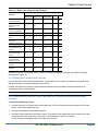
1
DTX5000-CTL-R2
ServSwitch DTX™ Control
Remotely manage and monitor multiple DTX
extender systems.
FCC and IC RFI Statements
Federal Communications Commission and Industry Canada Radio Frequency Interference
Statements
This equipment generates, uses, and can radiate radio-frequency energy, and if not installed and used properly, that is, in strict
accordance with the manufacturer’s instructions, may cause interference to radio communication. It has been tested and found to
comply with the limits for a Class A computing device in accordance with the specifications in Subpart B of Part 15 of FCC rules,
which are designed to provide reasonable protection against such interference when the equipment is operated in a commercial
environment. Operation of this equipment in a residential area is likely to cause interference, in which case the user at his own
expense will be required to take whatever measures may be necessary to correct the interference.
Changes or modifications not expressly approved by the party responsible for compliance could void the user’s authority to operate
the equipment.
This digital apparatus does not exceed the Class A limits for radio noise emission from digital apparatus set out in the Radio
Interference Regulation of Industry Canada.
Le présent appareil numérique n’émet pas de bruits radioélectriques dépassant les limites applicables aux appareils numériques de la
classe A prescrites dans le Règlement sur le brouillage radioélectrique publié par Industrie Canada.
Page 2
724-746-5500 | blackbox.com
NOM Statement
Instrucciones de Seguridad
(Normas Oficiales Mexicanas Electrical Safety Statement)
1. Todas las instrucciones de seguridad y operación deberán ser leídas antes de que el aparato eléctrico sea operado.
2. Las instrucciones de seguridad y operación deberán ser guardadas para referencia futura.
3. Todas las advertencias en el aparato eléctrico y en sus instrucciones de operación deben ser respetadas.
4. Todas las instrucciones de operación y uso deben ser seguidas.
5. El aparato eléctrico no deberá ser usado cerca del agua—por ejemplo, cerca de la tina de baño, lavabo, sótano mojado o cerca de
una alberca, etc..
6. El aparato eléctrico debe ser usado únicamente con carritos o pedestales que sean recomendados por el fabricante.
7. El aparato eléctrico debe ser montado a la pared o al techo sólo como sea recomendado por el fabricante.
8. Servicio—El usuario no debe intentar dar servicio al equipo eléctrico más allá a lo descrito en las instrucciones de operación. Todo
otro servicio deberá ser referido a personal de servicio calificado.
9. El aparato eléctrico debe ser situado de tal manera que su posición no interfiera su uso. La colocación del aparato eléctrico sobre
una cama, sofá, alfombra o superficie similar puede bloquea la ventilación, no se debe colocar en libreros o gabinetes que impidan el
flujo de aire por los orificios de ventilación.
10. El equipo eléctrico deber ser situado fuera del alcance de fuentes de calor como radiadores, registros de calor, estufas u otros
aparatos (incluyendo amplificadores) que producen calor.
11. El aparato eléctrico deberá ser connectado a una fuente de poder sólo del tipo descrito en el instructivo de operación, o como se
indique en el aparato.
12. Precaución debe ser tomada de tal manera que la tierra fisica y la polarización del equipo no sea eliminada.
13. Los cables de la fuente de poder deben ser guiados de tal manera que no sean pisados ni pellizcados por objetos colocados sobre
o contra ellos, poniendo particular atención a los contactos y receptáculos donde salen del aparato.
14. El equipo eléctrico debe ser limpiado únicamente de acuerdo a las recomendaciones del fabricante.
15. En caso de existir, una antena externa deberá ser localizada lejos de las lineas de energia.
16. El cable de corriente deberá ser desconectado del cuando el equipo no sea usado por un largo periodo de tiempo.
17. Cuidado debe ser tomado de tal manera que objectos liquidos no sean derramados sobre la cubierta u orificios de ventilación.
18. Servicio por personal calificado deberá ser provisto cuando: A: El cable de poder o el contacto ha sido dañado; u
B: Objectos han caído o líquido ha sido derramado dentro del aparato; o
C: El aparato ha sido expuesto a la lluvia; o
D: El aparato parece no operar normalmente o muestra un cambio en su desempeño; o
E: El aparato ha sido tirado o su cubierta ha sido dañada.
724-746-5500 | blackbox.com
Page 3
Trademarks Used in this Manual
Trademarks Used in this Manual
Black Box and the Double Diamond logo are registered trademarks of BB Technologies, Inc. Any other trademarks mentioned in this
manual are acknowledged to be the property of the trademark owners.
Page 4
724-746-5500 | blackbox.com
Table of Contents
Table of Contents
1
Technical Specifications
2
Product Overview
10
2.1
Introduction
10
2.2
Features and benefits
10
2.3
System Components
10
2.4
Upgrading the DTX Control Software
11
2.5
Safety precautions
11
3
Installation and Setup
14
3.1
Installing the Appliance
14
3.1.1
Rack mounting the DTX Control Appliance
14
3.1.2
Connecting the DTX Control appliance
14
3.1.3
Configuring Network Settings
15
3.2
3.3
4
5
9
Launching the DTX Control Appliance Web Interface
16
3.2.1
16
The DTX Control Explorer window
Configuring DTX Control Servers
18
3.3.1
Server properties
18
3.3.2
Server certificates
18
3.3.3
Email
20
3.3.4
Unit status polling
20
3.4
Backing up and Restoring Hub Servers Manually
20
3.5
Spoke Servers
21
3.6
Replication
23
3.6.1
Initial load
24
3.6.2
Incremental updates
24
3.6.3
Modify Push and Pull task periods of time
25
3.7
Fast Switch Enable
25
3.8
Next Steps
26
Units View Windows
27
4.1
Types of Units View Windows
27
4.2
Showing and Hiding Units
27
4.3
Units View Windows Fields
28
4.4
Multiple Unit Operations from a Units View Window
29
4.5
Unit Overview Windows
30
4.6
Unit Status Window
30
Managing Units
31
5.1
31
Using the Units Tab in the Explorer Window
724-746-5500 | blackbox.com
Page 5
Table of Contents
5.1.1
Ease of Installation
31
5.3
The Units All Window
31
5.3.1
Adding units via the Add Unit Wizard
32
5.3.2
Adding units from a range of IP addresses
33
5.3.3
Adding units on an IP subnet
34
5.5
Page 6
The Unit Overview Window
34
5.4.1
Changing unit properties
35
5.4.2
Configuring network settings for a transmitter or user station
35
5.4.3
Enabling Auto Login Mode for a DTX user station
36
5.4.4
Viewing version information
36
5.4.5
Rebooting a unit
36
5.4.6
Setting the Operating Mode for a DTX user station
36
5.4.7
Share Mode
37
5.4.8
Managing firmware upgrades
37
5.4.9
Viewing/changing target computer overview information
38
5.4.10 Managing user access to target computers
38
5.4.11 Changing target computer properties
38
5.4.12 Share Mode
39
Departments and Locations Windows
39
5.5.1
Importing DTX Control databases
40
5.5.2
Active media sessions
41
5.5.3
All active media sessions
41
5.5.4
Performing a forced log-out
42
Unit Sessions and Connections
43
6.1
Force and Follow Modes
43
6.1.1
Regular Follow Mode
43
6.1.2
Multi-video Follow Mode
44
6.1.3
Force Mode
44
6.2
7
31
5.2
5.4
6
Deleting units
Active Sessions
45
6.2.1
All active sessions
45
6.2.2
Active sessions on a target device
46
Grouping Units
47
7.1
Site, Department and Location Groups
47
7.2
Custom Fields
48
7.3
Unit Groups
49
7.3.1
Unit group hierarchy
51
7.3.2
Adding or deleting a unit group
53
7.3.3
Changing the unit group properties
53
724-746-5500 | blackbox.com
Table of Contents
8
9
Authentication Services
56
8.1
Supported Authentication Services
56
8.1.1
DTX Control internal authentication service
57
8.1.2
Active Directory external authentication service
58
8.1.3
Windows NT external authentication service
62
8.1.4
LDAP external authentication service
64
8.1.5
RADIUS external authentication service
67
8.1.6
TACACS+ external authentication service
69
8.2
RSA SecurID external authentication service
71
8.3
User Authentication Services Window
73
Managing User Accounts
75
9.1
User Accounts Windows
75
9.2
Adding User Accounts
76
9.3
Deleting User Accounts
78
9.4
Unlocking User Accounts
78
9.5
Resetting a User Account Password
78
9.6
Changing User Account Properties
79
9.6.1
Username
79
9.6.2
User password
79
9.6.3
User account restrictions and expiration settings
80
9.6.4
User group membership
80
9.6.5
Address
81
9.6.6
Phone contact
81
9.6.7
Email contact
81
9.6.8
User notes
81
9.6.9
Custom field properties
82
9.7
10
11
User Access Rights
82
User Groups
84
10.1
Built-in User Groups
85
10.2
Adding User-defined User Groups
86
10.3
Deleting User-defined User Groups
88
10.4
User Group Properties
88
10.5
Changing User Group Members
89
10.6
User Group Access Rights
89
Events and Event Logs
91
11.1
Email Notifications
91
11.2
Changing the Event Log Retention Period
93
724-746-5500 | blackbox.com
Page 7
Page 8
724-746-5500 | blackbox.com
Chapter 1 Technical Specifications
1 Technical Specifications
Table 1.1: DTX Control Appliance Technical Specifications
Network Connection
Number
2
Type
Ethernet, 10BaseT, 100BaseT, GigE
Connector
RJ-45
Serial Port
Number
1
Type
RS-232 serial
Connector
DB9 male
Mechanical
H xWxD
4.3 x 42.7 x 35.6 cm (1.7 x 16.8 x 14 in), 1 U form factor
Weight
5.9 kg (13 lb)
Power
AC Input Voltage
100 to 240 VAC
Rated Input Current
4A maximum
Rated Input Frequency
50 to 60 Hz
Rated Output Power
260 W maximum
Rated Output Voltages
+3.3 V (15 A), +5 V (25 A), +12V (18A), -12 V (1A)
BTU Rate
1400 Bus/hour (for rated output power of 260 W)
Environmental
Temperature
0° to 35° Celsius (32° to 95° Fahrenheit) operating
Humidity
10 to 90% noncondensing operating
Safety and EMC Approvals and Markings
USA (UL, FCC), Canada (cUL), Germany (TUV), European Union (CE),
Japan (VCCI), Russia (GOST), Korea (MIC) and Australia (C-Tick)
NOTE: Safety certifications and EMC certifications for this product are obtained under one or more of the following designations: CMN (Certification
Model Number), MPN (Manufacturer’s Part Number) or Sales Level Model designation. The designation that is referenced in the EMC and/or safety
reports and certificates are printed on the label applied to this product.
724-746-5500 | blackbox.com
Page 9
Chapter 2 Product Overview
2 Product Overview
2.1 Introduction
The DTX Control appliance is a secure, web browser-based, centralized enterprise management solution that allows
users to remotely manage and monitor multiple DTX Extender systems. The DTX Extender system, which includes a
transmitter and a user station, provides users with a full computer desktop experience from anywhere on the corporate
TCP/IP network, while maintaining the computers securely housed in a corporate data center. The addition of the DTX
Control appliance allows the user stations and transmitters that comprise the DTX Extender system to operate in
Desktop Mode. This mode allows a user to log in to any DTX user station and the system will connect automatically to
the transmitter that has been assigned to that user. Through Desktop Mode, the DTX Control appliance allows
administrators to remotely manage and monitor the networks of user stations and transmitters that comprise the DTX
Extender system.
NOTE: There are several types of DTX user stations and transmitters, but not all of them can communicate across platforms. For example, the
DTX 5000 user station can only communicate with its corresponding DTX 5000-T transmitter. However, the DTX 5001 and 5002 user stations and
their corresponding transmitters can communicate across both platforms. For more information on DTX user stations and transmitters, see the
ServSwitch DTX 500x User Guide.
2.2 Features and benefits
Web-based access and control
As a web browser-based management solution, the DTX 5000-CTL Management Appliance provides the operations,
administration and maintenance interface for the DTX Extender system. It also manages authentication, authorization,
initiation and removal of media sessions between the user station and transmitter. The DTX Control appliance provides a
centralized database for storing configuration, user, unit and system information allowing administrators to add, remove,
delete and change settings for managed appliances and users. In addition, the DTX Control appliance enables
authentication, access control, logging events and monitoring of target computers.
Security
Secure Socket Layer (SSL) encryption is used to encrypt DTX Control appliance system data. Users are authenticated
using the DTX Control appliance internal database or one of the external authentication methods available. See
Supported Authentication Services on page 56 for more information. For management functions, the DTX Control
appliance uses HTTPS (Hypertext Transfer Protocol with SSL encryption) to interact with the DTX Extender system.
NOTE: To access the DTX Control appliance through a firewall, you must ensure that the firewall uses the default HTTPS port 443.
NOTE: When the Fast Switch option is enabled, security protocols will be disabled and data will not be encrypted.
DTX extender system support
The transmitter connects externally to the video, audio and USB ports of the target computer and is attached directly to
the target computer. It captures, compresses and encrypts the computer’s media stream and transmits it to the DTX user
station over a standard TCP/IP network. The user station enables the desktop user’s keyboard, video, mouse and audio
devices to connect to the DTX Extender system.
2.3 System Components
The DTX Control software system contains the following components.
DTX Control software
The DTX Control software resides on the DTX Control server (hub or spoke) and provides a web gateway and services for
managing units (appliances and target devices) using a web browser. The gateway allows for web browser access.
724-746-5500 | blackbox.com
Page 10
Chapter 2 Product Overview
Administrators and users may connect to the DTX Control server from DTX Control software clients and use the DTX
Control Explorer windows to communicate with the system.
DTX Control server
The DTX Control server contains the DTX Control software. The server provides a centralized database for storing
configuration, user, unit and system information. It also provides services for authentication, access control and logging
events.
You may configure one or more spoke (backup) servers in addition to the hub server. The hub server is responsible for
maintaining the master copy of the database in a DTX Control software system. Only one server in a DTX Control
software system may be configured as the hub server.
Spoke servers perform database replication with the hub server. The hub server acts as the coordinator for database
replication between itself and all of the other spoke servers in a DTX Control software system. A hub server and a spoke
server both offer the same DTX Control software functionality to a user. The distinction of hub or spoke refers only to the
database replication role that the server plays and not with the functionality that the server provides. Adding one or more
spoke servers to a DTX Control software system provides redundancy.
After the hub server and optional spoke server(s) are configured, you may create and configure the type of access levels
for users within your network environment. You may also set up event logs to record full details of user access and other
events.
DTX Control software client
A DTX Control software client is a computer with a web browser that can access the DTX Control software installed on
the DTX Control server.
2.4 Upgrading the DTX Control Software
When upgrading to a newer version of the DTX Control software, all DTX Control servers should be upgraded at the same
time. The DTX Control hub server should be upgraded first, followed by each spoke server.
Before upgrading, a replication should be performed, then a backup immediately before and after upgrading the
DTX Control software (see Backing up and Restoring Hub Servers Manually on page 20).
The firmware for the appliances may also need to be upgraded in order to support new functionality in the DTX 5000CTL Management Appliance. The DTX Control appliance should work with the existing firmware revisions, but in cases
where new functionality is not supported until the firmware is upgraded, the DTX 5000-CTL Management Appliance will
indicate this in the graphical user interface (GUI).
2.5 Safety precautions
To avoid potentially fatal shock hazard and possible damage to equipment, please observe the following precautions:
•
Do not use a 2-wire power cord in any product configuration.
•
Test AC outlets at the target computer and monitor for proper polarity and grounding.
•
Use only with grounded outlets.
NOTE: The AC inlet is the main power disconnect.
CAUTION: Failure to observe the precautions in this section may result in personal injury or damage to equipment.
Observe the following general safety precautions when setting up and using BLACK BOX equipment.
•
Follow all cautions and instructions marked on the equipment.
Page 11
724-746-5500 | blackbox.com
Chapter 2 Product Overview
•
Follow all cautions and instructions in the installation documentation or on any cautionary cards shipped with the
product.
•
Do not push objects through the openings in the equipment. Dangerous voltages may be present. Objects with
conductive properties can cause fire, electric shock or damage to the equipment.
•
Do not make mechanical or electrical modifications to the equipment.
•
Do not block or cover openings on the equipment.
•
Choose a location that avoids excessive heat, direct sunlight, dust or chemical exposure, all of which can cause the
product to fail. For example, do not place a BLACK BOX product near a radiator or heat register, which can cause
overheating.
•
Ensure that the voltage and frequency of the power source match the voltage and frequency on the label on the
equipment.
•
AC power supplies have grounding- type three- wire power cords. Make sure the power cords are plugged into singlephase power systems that have a neutral ground.
•
Do not use household extension power cords with BLACK BOX equipment because household extension cords are
not designed for use with computer systems and do not have overload protection.
•
Ensure that air flow is sufficient to prevent extreme operating temperatures. Provide a minimum space of 6 inches (15
cm) in front and back for adequate airflow.
•
Keep power and interface cables clear of foot traffic. Route cables inside walls, under the floor, through the ceiling or
in protective channels or raceways.
•
Route interface cables away from motors and other sources of magnetic or radio frequency interference.
•
Stay within specified cable length limitations.
•
Leave enough space in front and back of the equipment to allow access for servicing.
When installing BLACK BOX equipment in a rack or cabinet, observe the following precautions:
•
Ensure that the floor’s surface is level.
•
Load equipment starting at the bottom first and fill the rack or cabinet from the bottom to the top.
•
Exercise caution to ensure that the rack or cabinet does not tip during installation and use an anti- tilt bar.
When using a desk or table, observe the following precautions:
•
Choose a desk or table sturdy enough to hold the equipment.
•
Place the equipment so that at least 50% of the equipment is inside the table or desk’s leg support area to avoid
tipping of the table or desk.
Cabling installation, maintenance and safety tips
The following is a list of important safety considerations that should be reviewed prior to installing or maintaining your
cables:
•
Maintain the twists of the pairs all the way to the point of termination, or no more that one-half inch untwisted. Do not
cut off more than one inch of jacket while terminating.
•
If bending the cable is necessary, make it gradual with no bend sharper than a one inch radius. Allowing the cable to
be sharply bent or kinked can permanently damage the cable’s interior.
•
Dress the cables neatly with cable ties, using low to moderate pressure. Do not over tighten ties.
•
Cross-connect cables where necessary, using rated punch blocks, patch panels and components. Do not splice or
bridge cable at any point.
724-746-5500 | blackbox.com
Page 12
Chapter 2 Product Overview
•
Keep CAT 5 cable as far away as possible from potential sources of EMI, such as electrical cables, transformers and
light fixtures. Do not tie cables to electrical conduits or lay cables on electrical fixtures.
•
Always test every installed segment with a cable tester. “Toning” alone is not an acceptable test.
•
Always install jacks so as to prevent dust and other contaminants from settling on the contacts. The contacts of the
jack should face up on the flush mounted plates, or left/right/down on surface mount boxes.
•
Always leave extra slack on the cables, neatly coiled in the ceiling or nearest concealed location. Leave at least five
feet at the work outlet side and 10 feet at the patch panel side.
•
Choose either 568A or 568B wiring standard before beginning. Wire all jacks and patch panels for the same wiring
scheme. Do not mix 568A and 568B wiring in the same installation.
•
Always obey all local and national fire and building codes. Be sure to firestop all cables that penetrate a firewall. Use
plenum rated cable where it is required.
Page 13
724-746-5500 | blackbox.com
Chapter 3 Installation and Setup
3 Installation and Setup
The following sections will help you install and set up your DTX Control appliance. Helpful topics in this chapter include
the following:
•
Installing the Appliance on page 14
•
Launching the DTX Control Appliance Web Interface on page 16
•
Replication on page 23
•
Next Steps on page 26
3.1 Installing the Appliance
3.1.1 Rack mounting the DTX Control Appliance
Rack mount safety considerations
•
Elevated Ambient Temperature: If installed in a closed rack assembly, the operating temperature of the rack
environment may be greater than room ambient. Use care not to exceed the rated maximum ambient temperature of
the switch.
•
Reduced Air Flow: Installation of the equipment in a rack should be such that the amount of airflow required for safe
operation of the equipment is not compromised.
•
Mechanical Loading: Mounting of the equipment in the rack should be such that a hazardous condition does not exist
due to uneven mechanical loading.
•
Circuit Overloading: Consideration should be given to the connection of the equipment to the supply circuit and the
effect that overloading of circuits might have on overcurrent protection and supply wiring. Consider equipment
nameplate ratings for maximum current.
•
Reliable Earthing: Reliable earthing of rack mounted equipment should be maintained. Pay particular attention to
supply connections other than direct connections to the branch circuit (for example, use of power strips).
NOTE: The DTX Control appliance may be rack mounted in a 1U configuration.
3.1.2 Connecting the DTX Control appliance
A typical DTX Control configuration includes the appliance, transmitters and user stations connected to the local area
network (LAN). A terminal, or a computer running a terminal emulation program, is connected to the serial port for
configuring basic network settings. The DTX Control appliance, transmitters and user stations, as well as user accounts,
are then configured from the browser interface to the DTX Control appliance.
To connect the DTX Control appliance:
WARNING: To reduce the risk of electric shock or damage to your equipment:
- Do not disable the power cord grounding plug. The grounding plug is an important safety feature.
- Plug the power cord into a grounded (earthed) outlet that is easily accessible at all times.
- Disconnect the power from the target computer by unplugging the power cord from either the electrical outlet or the target computer.
1. Attach one end of the supplied power cord into the back panel of the DTX Control appliance and attach the other end
to an appropriate AC power source. The DTX Control appliance has a power control button on the front panel.
2. Connect the LAN Port 1 Ethernet port on the back panel of the DTX Control appliance to the LAN to which the
transmitters and user stations are connected using standard UTP cables.
724-746-5500 | blackbox.com
Page 14
Chapter 3 Installation and Setup
NOTE: The DTX user stations and transmitters must be connected to LAN port 1. However, you can access the DTX Control appliance using the
browser on a computer connected to either LAN port 1 or LAN port 2.
3.1.3 Configuring Network Settings
To assign an IP address to the DTX Control appliance, you must establish a connection to the serial menu first, then use
the options on the serial console menu to configure the network settings for each of the LAN ports on the DTX Control
appliance.
NOTE: If you are connecting to only one LAN, only LAN port 1 needs to be configured.
To configure the network settings of the DTX Control appliance:
1. Connect a terminal or a computer that is running a terminal emulation program to the serial port on the back panel of
the DTX Control appliance.
2. Start a session with the following port settings:
•
Serial speed: 9600 bps
•
Data length: 8 data bits
•
Parity: None
•
Stop Bits: 1
•
Flow Control: None
3. Once a connection is established, a serial console menu appears.
4. Type 2 to configure any of the following network settings:
•
Set eth speed
•
Choose using DHCP or defining an IP address
•
Type subnet mask
•
Type gateway IP address
•
Select default gateway
•
Define primary DNS and secondary DNS
NOTE: The IP address on LAN port 1 must not change during operation of the appliance. Always configure LAN port 1 with a static IP address or, if
using DHCP, ensure that the IP addresses are assigned with unlimited lease times. There is no restriction on how LAN port 2 can be configured. It
is also possible to configure DNS on the DTX Control appliance if it is required for administrator access through a web browser.
NOTE: If DHCP is selected, the DTX Control appliance must be rebooted for the change to take effect.
5. Type 3 to set the time and date.
a. Select the appropriate timezone. Determine the offset in hours between your local time and Coordinated
Universal Time (UTC). A negative offset indicates that the time zone is west of UTC and a positive offset
indicates that the time zone is east of UTC. For example, Eastern Standard Time would be -5.
b. Input the year, month, day, hour, minute and seconds. The year requires four digits, while the rest of the digits
can be either one or two digits.
6. Type 0 and press Enter to exit.
Page 15
724-746-5500 | blackbox.com
Chapter 3 Installation and Setup
3.2 Launching the DTX Control Appliance Web Interface
The DTX Control appliance operates using default Internet Explorer settings. In the event that the default Internet
Explorer settings have been altered, SSL and Javascript must be enabled to successfully access the DTX Control
appliance.
To launch the DTX Control appliance web interface:
1. Launch Microsoft® Internet Explorer.
2. In the address field of the browser, enter the IP address assigned to the DTX Control appliance LAN port 1. Use
https://xxx.xx.xx.xx as the format.
NOTE: If DNS is enabled, the address is the fully qualified host name assigned to the DTX Control appliance.
3. Press Enter. The DTX Control appliance login screen appears.
4. Enter the login username and password. The first time you access the DTX Control appliance, enter admin as the
username and Admin1 as the password. For security reasons, you should change the default admin password. The
admin account is authorized to perform all configuration and access all managed devices and cannot be removed or
renamed. Click Login and the DTX Control Explorer window appears.
3.2.1 The DTX Control Explorer window
Once a user has been logged in and authenticated, the Explorer window is displayed. From the Explorer window, you can
view, access and manage units and users via the DTX Control appliance.
Figure 3.1: Explorer Window Areas
Table 3.1: Explorer Windows Area Descriptions
Letter
Description
A
Top option bar - Use the top option bar to log out of a software session, or to access online help. The name of the logged in user is displayed on
the left side of the top option bar.
B
Tab bar - Use the tab bar to display and manage units, user accounts, system settings and reports.
C
Top navigation bar - The options in the top navigation bar vary depending on the active tab in the tab bar. Topics relevant to each selection
display in the side navigation bar.
D
Side navigation bar - Use the side navigation bar to select system information to display or edit in the contenarea.
E
Content area - The information specified by the tab bar, top navigation bar and side navigation bar selections is displayed and changed in the
content area.
724-746-5500 | blackbox.com
Page 16
Chapter 3 Installation and Setup
Using the side navigation bar
Use the side navigation bar to display windows or perform operations. The contents of the side navigation bar vary,
depending on the tab and top navigation bar options that are in use.
The arrows displayed in the side navigation bar indicate where sub-options are available. You can display these items by
clicking the main link. Where no arrow is displayed, clicking the link brings you directly to the option you have selected.
Displaying pages
Multiple page windows contain menu options that may be used to navigate from one display to another. You can click the
Select All checkbox to select all items on a page. Enabling this checkbox selects all the items listed on a page regardless
of whether the entire page is visible. However, for multi-page displays, items listed on other pages will not be included in
the selection. All screens that show lists, units, sessions and target computers automatically refresh every 10 seconds.
Using keyboard commands
In addition to using a mouse, you can use keyboard commands to select and change items in windows.
Page 17
724-746-5500 | blackbox.com
Chapter 3 Installation and Setup
Table 3.2: General Keyboard Commands
Key
Tab
Description
Transfers focus to the next control in the window, including the calendar
Shift-Tab Transfers focus to the previous HTML control
3.3 Configuring DTX Control Servers
This section describes how to configure DTX Control server properties, backup and restore hub servers and manage
spoke servers. This can be done from the System tab in the DTX Control Explorer window. It is recommended to
configure your DTX Control server before adding users and units.
3.3.1 Server properties
To display server properties:
Click the System tab. Click on DTX Control in the top navigation bar and Identity will automatically be selected in the side
navigation bar. The Server Identity Properties window will open. The top of the side navigation bar will indicate the name
of the DTX Control server.
Table 3.3: Server Properties
Property
Description
Identity
Name of the DTX Control server, the server’s role (hub or spoke), EID, serial and MPN numbers, and database and manager
build versions. The add-on version is also indicated.
Network
IP address (*) and port used by clients to access the server using the HTTPS (SSL) protocol.
Email
IP address of the SMTP (Simple Mail Transfer Protocol) server that is used by the DTX 5000-CTL Management Appliance to send
email notifications.
Target Computer Enables/disables unit status polling for the DTX Control server, and specifies the delay between polling cycles and the number of
Polling
managed appliances that will be concurrently polled.
Spoke Servers
Enables you to manage the DTX Control spoke servers in your system.
3.3.2 Server certificates
DTX Control administrators manage server certificates.
Security alerts
The DTX 5000-CTL Management Appliance uses SSL (Secure Sockets Layer) to securely communicate between the
DTX Control hub server and DTX Control clients. SSL provides secure authentication using certificates, which is data
that identifies the PC with which communication will occur. A certificate is typically verified by another certificate from a
trusted certificate authority.
NOTE: When the Fast Switch option is enabled, security protocols will be disabled and data will not be encrypted.
When the DTX 5000-CTL Management Appliance is initially installed, it generates a self-signed certificate for use with
DTX Control clients. To replace this, a DTX Control administrator may create a Certificate Signing Request (CSR) to
submit to a trusted third party Certificate Authority (CA) for signature. The administrator may then replace the generated
certificate with the new one. If the generated certificate is not replaced, the web browser will prompt a user whether to
trust the generated certificate when a DTX Control client session is started.
Three tests are performed on a certificate each time a DTX Control client connects to the DTX Control hub server:
•
Does the client web browser trust the certificate issuer?
724-746-5500 | blackbox.com
Page 18
Chapter 3 Installation and Setup
•
Has the certificate expired?
•
Does the name on the DTX Control server certificate match the name the DTX Control client used to access the DTX
Control server?
A Security Alert dialog box will appear if the answer to any of the three questions is No. To prevent the Security Alert
message box from appearing when you connect to the DTX Control hub server, all three questions must be answered
Yes. When a Security Alert dialog box appears, you have the following choices:
•
If you click Yes, a connection will be made with the DTX Control hub server and the DTX Control login window will
appear, but the Security Alert dialog box will continue to appear each time you connect to the hub server.
•
If you click No, a connection will not be made with the DTX Control hub server.
•
If you click View Certificate, you may install the certificate; see below.
To correct certificate security alerts for client and hub server connections:
1. From the DTX Control client, open a client session. The Security Alert dialog box will appear.
2. Click View Certificate. The Certificate dialog box will appear.
3. Click Install Certificate. See the Internet Explorer documentation for more information.
4. Once the certificate is installed, ensure that the time setting on the DTX Control client PC is within the Valid
from...to... dates and that the Issued to and Issued by fields exactly match.
Invalid to...from dates typically occur when the DTX 5000-CTL Management Appliance is installed on a server
that is set to an invalid time. When a DTX Control client that is set to a valid time connects to the DTX Control
server that is set to an invalid time, the following warning will appear in the Security Alert dialog box: The security
certificate date is invalid.
To create a CSR:
1. Click the System tab - DTX Control.
2. Click Certificate in the side navigation bar. The DTX Control Server Certificate Properties window will open.
3. Click Get CSR. A File Download dialog box will appear.
4. Click Open. The CSR is downloaded and displays in the configured text editor.
-orClick Save. The Save As dialog box will appear. Select a directory and filename and click Save to save the CSR.
5. Submit the CSR generated request to a CA to obtain a signed server certificate.
6. Update the DTX Control server to use the certificate created by the CA.
Managing hub and spoke server certificates
When a spoke server is registered with a hub server, a certificate trust relationship is established between the two
servers. Certificate information must match on the hub server and the spoke servers for communication to take place
between the servers. If the spoke server certificate is subsequently changed, a certificate mismatch will occur.
To update the certificate of a spoke server on the hub server:
NOTE: Certificates may only be viewed by DTX Control administrators and user administrators.
1. On the hub server, click the System tab - DTX Control.Server will automatically be selected in the top navigation bar
and the name of the DTX Control hub server will appear at the top of the side navigation bar.
2. Click Spoke Servers in the side navigation bar. The Spoke Servers window will open.
Page 19
724-746-5500 | blackbox.com
Chapter 3 Installation and Setup
3. In the Spoke Servers window, click Certificate. The Spoke Server Certificate window will open including information
about the spoke server certificate (Actual Certificate) and the certificate registered for this spoke server on the hub
server (Registered Certificate).
4. The window displays the certificate on the spoke server and the certificate registered on the hub server.
If the DTX 5000-CTL Management Appliance cannot obtain the certificate information from the spoke server, a
message will appear at the bottom of the Server Certificate - Spoke Server window. The message states:
Remote server is not responding. Information displayed may not match remote side.
•
If the certificate information does not match, go to step 5.
•
If the certificate information matches, go to step 6.
5. Click Update. The spoke server certificate information will be updated on the hub server.
6. Click Close. The Spoke Servers window will open.
3.3.3 Email
To specify email properties:
1. Click the System tab, DTX Control.
2. Click Email in the side navigation bar. The Server Email Server Properties window will open.
3. Type a new address for the SMTP server that sends email notifications as a domain name or an IP address in
standard dot notation (xxx.xxx.xxx.xxx).
4. If your SMTP server requires login credentials, select Login required to access SMTP server and type a username
and password, then confirm the password.
5. Click Save to store DTX Control email property information in the DTX Control database on the host.
3.3.4 Unit status polling
To use unit status polling:
1. Click the System tab.
2. Click Unit Status Polling in the side navigation bar. The Server Unit Status Polling Properties window will open.
3. Select Enable unit status polling.
4. Type the number of seconds to wait between polling cycles (from 30-999 seconds). The default is 900 seconds (15
minutes). A smaller value results in greater accuracy.
5. Type the number of managed appliances that may simultaneously be polled to obtain status information (from 1-25
units). The default is 5. A larger number results in faster speed.
6. Click Save to store unit status information in the DTX Control database on the host.
3.4 Backing up and Restoring Hub Servers Manually
To manually backup or restore your hub server:
NOTE: Manual backup and restore procedures require DTX Control administrator privileges.
1. Click the System tab.
2. Click DTX Control in the top navigation menu, then click Tools in the side navigation bar.
3. If you are manually backing up your hub server, click the Backup System tool icon.
724-746-5500 | blackbox.com
Page 20
Chapter 3 Installation and Setup
-orIf you are restoring a 3.0.0 or greater database backup, click the Restore System tool icon.
4. Follow the wizard and pop-up instructions.
3.5 Spoke Servers
Information on the hub server is replicated on one or more spoke servers. Information about each spoke server, such as
the IP address, port number and certificate, is stored in the hub server’s database. You may specify up to 15 DTX Control
servers as spoke servers.
NOTE: The DTX Control software versions of the spoke server and hub server must match in order to register a spoke server. For example, you
may not register a spoke server running DTX Control software version 3.1 with a hub server running DTX Control software version 3.2.
A spoke server may be created by converting a hub server. To do this, register the hub server as a spoke to another
DTX Control hub server. The DTX Control system data on the hub server being converted will be lost and the converted
hub server will replicate the data of the new specified hub server.
You may also change the properties of a spoke server or remove spoke servers from your system.
To display a list of spoke servers:
NOTE: The Spoke Servers window is only available on the hub server.
1. Click the System tab.
2. Click DTX Control in the top navigation bar. The side navigation bar will include the name of the server to which you
are logged in.
3. Click Properties in the side navigation bar, and then click Spoke Servers. The Spoke Servers window will open.
You may change the fields that display by using the Customize link.
Each spoke server in the list includes status.
Table 3.4: DTX Control Spoke Server Status
Status
Cause
Responding
Normal operation. The hub and spoke servers are communicating with each other using HTTPS.
Not responding
The hub and spoke servers cannot communicate with each other using HTTPS. This typically indicates a network communication
error. Ensure that network connectivity is occurring between the two servers.
Hub/Spoke
Versions Not
Compatible
The versions of DTX Control software on the hub and spoke servers are not compatible.
Certificates Do
Not Match
Certificates on the hub server and spoke servers do not match.
Invalid Server or A server responded, but it is not compatible with the DTX Control software. This typically occurs when communication is attempted
Versions Not
with a server that does not contain the software, or if either server contains an older version of the software. Ensure that both
Compatible
servers are running the same DTX Control software version.
To add a spoke server:
1. Install the DTX 5000-CTL Management Appliance on the computer that will be used as a spoke server.
2. Configure the computer as a spoke server.
To register a hub server as a spoke server:
Only DTX Control administrators may access this procedure.
Page 21
724-746-5500 | blackbox.com
Chapter 3 Installation and Setup
NOTE: When registering a hub server as a spoke server on another DTX Extender system, the information on the hub server being registered will
be lost. Its database will be updated to match the new hub server to which it is being registered.
1. Click the System tab.
2. Click DTX Control in the top navigation bar. The side navigation bar will include the name of the server to which you
are logged in.
3. Select Tools in the side navigation bar. The Server Tools window will open.
4. Click the Register as Spoke Server icon or text. The Register Spoke Server Wizard will appear.
5. The Type in Hub Server Address window will open.
a. Type the IP address of the hub server in standard dot notation (xxx.xxx.xxx.xxx) or the domain name of the hub
server.
b. Type the port number for the hub server.
If the default hub server port value (443) is modified, you must specify it when registering a spoke server
so that register requests will be sent to the correct port on the hub server. For example, if the IP address
of the hub server is 10.0.0.1 and the port number is changed to 444, type https://10.0.0.1:444/dtview in the
Address field of the Register Spoke Server Wizard.
c. Click Next.
6. The Operation in Progress window will open briefly, followed by the Accept Hub Server Certificate window. Click
Next.
7. The Type in Hub Server Administrator Credentials window will open. Click Next.
8. Type the name of a user with DTX Control administrator privileges on the hub server. Type a password for the user.
Click Next.
9. The Operation In Progress window will open. The configuration of the spoke server will be saved to the database of
the hub server and the spoke server’s certificates will be installed on the hub server.
10. The Completed Successful window will open when the spoke server has been added.
11. Click Finish.
To change spoke server network properties:
NOTE: Spoke server network settings may need to be changed by DTX Control administrators when network settings are changed and the hub
server did not automatically detect the changes. When changing the network settings, ensure that a port mismatch does not occur between the hub
server and the spoke server.
1. On the hub server, click the System tab.
2. Click DTX Control in the top navigation bar. The side navigation bar will include the name of the server to which you
are logged in.
3. Click Properties in the side navigation bar, and then click Spoke Servers. The Spoke Servers window will open.
4. Click on the name of the spoke server whose network properties you wish to change. The Spoke Server Network
Properties window will open.
5. Change any of the following network settings:
•
Type a new computer name to use as the spoke server.
•
Type a new address in standard dot notation (xxx.xxx.xxx.xxx) for the spoke server.
•
Type a new port number for the spoke server.
724-746-5500 | blackbox.com
Page 22
Chapter 3 Installation and Setup
6. Click Save and then click Close. The Spoke Servers window will open.
To delete a spoke server:
1. On the hub server, click the System tab.
2. Click DTX Control in the top navigation bar. The side navigation bar will include the name of the server to which you
are logged in.
3. Click Properties in the side navigation bar, and then click Spoke Servers. The Spoke Servers window will open.
4. Click the checkbox to the left of the spoke servers you wish to delete. To delete all spoke servers, click the checkbox
to the left of Name at the top of the list.
5. Click Delete. A confirmation dialog box will appear.
6. Confirm or cancel the deletion.
NOTE: When a spoke server is deleted, it is no longer allowed to communicate with the hub server. Only spoke servers that are no longer active
should be deleted. If a spoke server is still active, it may be re-registered using the Register Spoke Server wizard.
Promoting spoke servers
Promoting a spoke server to be a hub server is usually done only if the current hub server is no longer operational and will
not be brought back into service. (For less severe problems with a hub server, the backup and restore operations can be
used.)
If a spoke server must be promoted, be sure to run the replication task, if possible on all other spoke servers, then on the
spoke server being promoted, immediately before the promotion. This will prevent loss of data from the other spoke
servers. See Replication on page 23 for more information.
(After the promotion of a spoke server to a hub, if the server that was originally the hub becomes operational again, it will
have to register as a spoke server, since a system can have only one hub server.)
To promote a spoke server to be a hub server:
1. On the spoke server, click the System tab.
2. Click Tools in the side navigation bar.
3. Click Promote to hub server. The Promote Hub Server Wizard will appear.
4. Follow the prompts and heed the cautionary warnings in the wizard. The spoke server on which the wizard is running
will become the hub server, and the other spoke servers will be advised of the changed configuration.
3.6 Replication
Replication is a task that synchronizes the hub and spoke server databases. By default, replication runs every 12 hours
on each spoke server. A spoke server’s first replication occurs automatically when the spoke server is added to the
DTX Control system. You may change the interval that the replication task runs on each spoke server, or you may initiate
an immediate replication.
During replication, the spoke server sends all of its database changes since the last replication to the hub server. The hub
server then incorporates those changes and sends all of its database changes since the last replication to the spoke
server (excluding the changes that spoke server just sent to the hub server).
If an item is added on a spoke server, and another item with the same name (but perhaps with different configuration
parameters) is added on the hub server, then after replication, both items will appear on both the hub and spoke servers,
with a tilde (~) and a number added to one of the names. The administrator should handle the issue appropriately - in some
cases, the duplicate item may need to be renamed; in others, the duplicate item should be deleted.
Page 23
724-746-5500 | blackbox.com
Chapter 3 Installation and Setup
When different changes are made to one existing item, two outcomes are possible. For example, assume an item is
added and configured on the hub server and is then replicated to the spoke server. Later, an administrator changes
something about the item on the spoke server. Another administrator then changes something about the item on the hub
server. When the replication task runs, two things may happen.
In a few instances where no conflict occurs, both changes will be incorporated and replicated. For example, if the hub
server’s administrator adds username JaneDoe to the existing user-defined user group Accounting and the spoke server’s
administrator adds username JohnDoe to the Accounting user group, both names will be added and replicated.
In most other instances where the changes are mutually exclusive or some other conflict occurs, the most recent change
will be the only change accepted and replicated. For example, if the hub server’s administrator associates a unit with the
Miami site, and the spoke server’s administrator associates the same unit with the Chicago site, the change that was
made closest to the time of replication (that is, the most recent change) will be accepted and replicated.
This emphasizes the importance of ensuring the hub and spoke servers’ clocks are synchronized.
The exception to the last-change rule is when one of the actions deletes an item - in that case, the deletion is accepted
and replicated, regardless of timing. For example, if a unit was deleted on the hub server, and then the contact information
for the same unit was changed on the spoke server a minute later, the unit will be deleted when the replication task is run.
On a spoke server, you may enable a replication task property that forces the spoke server to retrieve a snapshot of the
hub database rather than synchronizing changes back and forth. The snapshot is a copy of the hub at the time of the
operation. This feature is not normally used; it is intended to help recover a system when replication has failed.
3.6.1 Initial load
NOTE: The DTX Control appliance is configured as hub by default.
When a DTX Control appliance is registered as spoke server into another DTX Control appliance, all the data in the spoke
is deleted and overwritten with the data from the hub. This process is called initial load. Once the initial load is completed,
both DTX Control appliances have the same information.
3.6.2 Incremental updates
The incremental updates are done by the pull and push tasks which are executed every period of time (by default 1
minute) by each spoke. The push task takes care of sending all the changes to the hub, while the pull task retrieves
changes from the hub.
If communication between the hub and a spoke is broken, changes are queued in both sides. Upon communication being
reestablished, the push and pull tasks send and retrieve all the changes since the last time the replication was
successful.
To register a DTX Control appliance as a spoke server:
NOTE: Because the spoke database gets deleted in this operation, BLACK BOX recommends making a backup copy of the spoke database first.
1. Click on System - DTX Control - Tools.
2. Click Register as Spoke Server wizard.
3. Click Next.
4. Type the hub's IP address and port (default is 443) and click Next.
5. On the Accept Hub Server Certificate Page, click Next to accept the hub certificate.
6. Enter the hub administrator username and password and click Next.
724-746-5500 | blackbox.com
Page 24
Chapter 3 Installation and Setup
7. Wait until the registration process ends. In this step all the data in the spoke is deleted and overwritten with the data
from the hub.
8. After the registration process is complete, click Finish to exit the wizard.
To promote a DTX 5000-CTL Management Appliance from spoke to hub:
Once a DTX 5000-CTL Management Appliance has been registered as spoke of another DTX 5000-CTL Management
Appliance hub, you can promote spokes to work as a hub. The old hub will become a new spoke of the promoted DTX
5000-CTL Management Appliance.
In the spoke DTX 5000-CTL Management Appliance:
1. Click on System - DTX Control - Tools.
2. Click Promote to Hub Server wizard.
3. Click Next in the Welcome page.
4. Click Next in the Confirm Server Promotion page.
5. Wait until the promotion process ends. In this step the spoke is promoted to hub and sends request to all the other
servers to become spokes.
6. Click Finish to exit the wizard and go to the Server Tools page.
To delete a spoke server registration using the Spoke Server view
You can delete a spoke registration using the Spoke Server view. If the spoke is deleted, the pull and push tasks will still
run in the spoke, but the requests are not accepted by the hub.
1. In the hub DTX 5000-CTL Management Appliance, click on System - DTX Control - Properties - Spoke Servers to
show the Spoke Server view.
2. Check the box of the spoke server registration to be deleted.
3. Click the Delete button and confirm the operation. The spoke server is no longer listed in the Spoke Server view. Any
change in the spoke database will not be replicated to the hub, and any change in the hub or the other spokes will not
be replicated to that spoke.
NOTE: You can register the spoke with the hub again using the Register as Spoke Server wizard.
3.6.3 Modify Push and Pull task periods of time
The Pull and Push task are executed during specific periods of time.
To change the default time values using the Database Replication Properties page:
1. In the spoke DTX 5000-CTL Management Appliance, click on System - DTX Control - DB Replication to show the
Database Replication Properties page.
2. Edit the time values.
3. Click Save. You must restart the server to allow the changes take effect.
NOTE: These properties are only used by the spoke server.
3.7 Fast Switch Enable
The Fast Switch Enable system option results in shorter connection times.
Page 25
724-746-5500 | blackbox.com
Chapter 3 Installation and Setup
NOTE: When the Fast Switch option is enabled, security protocols will be disabled and data will not be encrypted.
To enable the Fast Switch Enable system option:
1. Click System - DTX Control..
2. Click Fast Switch in the side navigation bar.
3. Click the Fast Switch checkbox to enable or disable the option. All appliances will be rebooted for the change to take
effect.
NOTE: Fast Switch Enable is disabled in the DTX Control factory default settings.
NOTE: When the DTX Control discovers a new unit that you've added to the system, it will automatically enable or disable the Fast Switch Enable
system option to match the current system settings.
3.8 Next Steps
At this point, only the administrator can log in to the DTX Control appliance. Now the administrator may choose to add
and manage units or set up additional user accounts. Users can also add and manage units if they are assigned access
rights by the administrator.
To add and manage units, see:
•
Units View Windows on page 27
•
Managing Units on page 31
•
Unit Sessions and Connections on page 43
•
Grouping Units on page 47
To configure authentication services and units, see:
•
Authentication Services on page 56
•
Managing User Accounts on page 75
•
User Groups on page 84
724-746-5500 | blackbox.com
Page 26
Chapter 4 Units View Windows
4 Units View Windows
Units View windows display list of units that have been added to the DTX Control database.
A user must have unit view access rights to open Units View windows. Also, units will not display if they are hidden.
Each Units View window contains one or more information fields.
Units are displayed in a table format with column headings. Use the checkbox to the left of each unit name to
select/deselect the unit for an operation. To select all the units on a page, click the checkbox at the left of all the column
headings at the top of the list - this is usually to the left of the Name column. Clicking this Select All checkbox will
automatically enable the checkboxes for all units on that page. To deselect items that were previously selected, click on
the checkbox.
When you click the checkbox at the top of the list, all units on the current page are selected (or deselected if they were
previously all selected). If the list of units spans more than one page, units on subsequent pages will not be selected. You
can specify how many items will appear on a Units View page (that is, the number of rows).
4.1 Types of Units View Windows
There are four types of Units View windows, which are accessed by clicking tabs and side navigation bar links.
Any Units View window that contains managed appliances may also be viewed using the topology feature, which
displays a hierarchical structure.
•
All Appliances: The Appliances - All window lists all managed appliances.
•
Appliance Type: Appliance Type windows list all managed appliances of a particular type. The Appliance Type links
in the side navigation bar are listed under Appliances - All.
An appliance type will only be listed in the side navigation bar if an appliance of that type has been added to the
DTX Control database and the user has access to it.
•
Target Devices: If target device types have been created, their links in the side navigation bar are listed under Target
Devices - All.
•
Mixed Views: Mixed view windows may contain managed appliances, target devices or both. Several links in the side
navigation bar will open mixed view Units View windows.
•
Recently Accessed - Units that the user has accessed most recently.
•
Groups - Units that have been assigned to a personal or global unit group.
•
Sites - Units that have been assigned to a site.
•
Departments - Units that have been assigned to a department.
•
Locations - Units that have been assigned to a location.
•
Custom fields - Units that have been assigned to custom groups. These group names may also have custom
field labels.
4.2 Showing and Hiding Units
Hiding turns off the display of units in the window, but does not remove the units from the DTX Control system.
To hide a unit:
1. In a Units View window, click Customize. The Units View Customization window will open.
2. Click Visibility in the Available Fields column and then click Add. Visibility will be moved to the Fields to Show
column.
724-746-5500 | blackbox.com
Page 27
Chapter 4 Units View Windows
3. Enable the Show hidden items checkbox if you wish to display hidden units in the Units View Customization window
with a transparent icon.
4. Click Save and then click Close. The window will open, containing the Visibility column. The Visibility column will
display Hide for each unit.
5. Click Hide for each unit.
The display of the selected unit will be turned off in the Units View window if Show hidden items was not selected
in the Units View Customization window.
If Show hidden items was selected, the hidden unit will appear with a transparent icon.
To hide multiple units with one operation:
1. In a Units View window, click the checkbox next to the units you want to hide from display. To select all units on the
page, click the checkbox to the left of Name at the top of the list.
2. Click Operations, then select Hide Units from the drop-down menu.
To show hidden units:
1. In a Units View window click Customize. The Units View Customization window will open.
2. Click Visibility in the Available Fields column and then click Add. Visibility will be moved to the Fields to Show
column.
3. Click Show hidden items.
4. Click Save and then click Close. The Units View window will open, containing the hidden items and the Visibility
column. Hidden items will have a transparent icon and the Visibility field will contain Show.
5. Click Show in the Visibility column for the unit(s) you want to display. The unit will be made visible, the icon will no
longer be transparent and the Visibility field will change to Hide.
4.3 Units View Windows Fields
The following fields may appear in Units View windows.
•
Name in DTL Control - Name of the unit as defined in the DTX Control database. Click on the name to display or
change unit information.
•
Type - Type of target device or managed appliance model. Managed appliance types cannot be changed; to assign a
type to a target device.
• Status - Current activity level of a unit. Table 4.1 lists and describes the possible values.
Table 4.1: Unit Status Values
Unit type
Status and Icon
Icon Description
Any unit
Idle
N/A The unit is powered up with no connection.
Any unit
In Use
The unit has at least one active connection.
Any unit
Status Unknown
The status of the unit was reported to the software but cannot be obtained for an unknown reason.
Target
devices
No Power
The target device is powered down.
Target
devices
No device attached
(topology view only)
Managed
Not Responding
appliances
Page 28
N/A The port does not have a target device attached.
The managed appliance did not provide status information. This may occur for multiple reasons, such as
the appliance is not powered up or it is disconnected from the DTX Control system.
724-746-5500 | blackbox.com
Chapter 4 Units View Windows
4.4 Multiple Unit Operations from a Units View Window
From a Units View window, you may delete one or more units or assign access rights for one or more units.
You may also use the Operations button/menu to initiate certain actions on one or more units.
•
Hiding units from view
•
Reboot
•
Show version
•
Change unit properties
Custom operations defined in plug-ins may also be listed in the Operations menu.
A given action will be available only if at least one of the selected units supports the action. If a selected unit does not
support the operation, it will be reported as such in the results window.
When one of these multiple unit operations is initiated and confirmed (if needed), a system task is created that will
perform the operation on each unit. The Multiple Unit Operation window will open, indicating the operation has been
submitted. This window contains a link that directs the user to the Operations Results window for the task.
To initiate and view results from multiple unit operations from a Units View window:
1. In a Units View window, initiate the multiple unit operation as described in the procedures referenced above. If
prompted, confirm the operation.
2. The Multiple Unit Operation window will open, indicating the operation has been submitted.
If you do not want to view the results of the operation, click Close and skip the rest of this procedure.
To view the results of the operation, click Click here to view results.
3. The Operations Results window will open, listing all multiple unit operations and any unit tasks that have been
initiated. The entry for each operation includes:
•
Name of the operation
•
When the operation started
•
When the operation finished (blank if not yet complete)
•
Status or result of the operation
You may also access this window at any time by clicking the Units tab, then clicking Operation Results in the
side navigation bar.
4. To view the results for an individual operation, click on the name. The Operation Results window for that operation
type will open, indicating:
•
Status - Current status of the task
•
Summary - Number of successful/failed/total unit operations (for example, the summary of an operation with a
status of ‘Rebooting the unit(s)’ might contain a 2/0/3 summary - 2 successful, 0 failed and 3 total units)
•
Name of the operation
•
Type of unit
•
When the operation started
•
How long the operation took
•
Status or result of the operation on the unit
5. Click Close.
724-746-5500 | blackbox.com
Page 29
Chapter 4 Units View Windows
4.5 Unit Overview Windows
You may change the overview information for one target device from a Unit Overview window. From a Units View
window, you can change the type or icon for several target devices in one operation. This may be helpful when you want
to assign the same values to several units.
To change overview information for a target device:
1. In a Units View window containing target devices, click on the name of a target device. The Unit Overview window
will open.
2. Enter a name for the target device.
3. Enter a type for the target device.
4. Select a new icon for the target device using the arrows.
5. Click Save and then click Close. The Units View window will open. If you added a type that was not previously
defined, it will appear under Target Devices in the side navigation bar.
To change the name of a managed appliance from the Unit Overview window:
1. Under Unit Settings - Summary, click on the name of an appliance. The Unit Overview window will open.
2. Type a name for the managed appliance. (You cannot change the type.)
3. Click Save and then click Close. The Units View window will open.
4.6 Unit Status Window
To use the Unit Status window:
1. Click the Units tab, then click Unit Status in the side navigation bar.
2. The Unit Status window opens.
3. You can filter what units are displayed by selecting a status from the Filter menu. Each unit status is color-coded. The
default filtered status is Active Status which displays only currently active units.
4. You can select how often the Unit Status is updated by selecting a time from the Interval menu.
5. You can view the Unit Overview window by double-clicking the unit name, or right-clicking the unit name and
selecting Show Unit Overview.
Page 30
724-746-5500 | blackbox.com
Chapter 5 Managing Units
5 Managing Units
This chapter describes how to manage unit properties and settings, access rights and local account settings, and how to
view unit asset and usage reports.
5.1 Using the Units Tab in the Explorer Window
From the Units tab in the DTX Control Explorer, you can manage user operations such as adding and deleting units,
changing unit properties and upgrading your firmware. When you click the Units tab, the Units - All window displays.
NOTE: In the DTX Control Explorer, the term “units” refers to transmitters and/or user stations.
5.1.1 Deleting units
To delete a unit:
1. In a Units - All window, click to select the checkbox next to the unit name. To delete all units on the page, click to
select the checkbox to the left of the Name field at the top of the list.
2. Click Delete. The unit(s) is immediately removed from the DTX Control database and disappears from the list.
5.2 Ease of Installation
The Ease of Installation feature removes the need to manually update transmitters and receivers via the local serial port,
allowing parameters to be configured from within the DTX Control appliance web interface.
To change device parameters:
1. Click the Units tab. Select the device to be configured.
2. Select Properties in the side navigation bar, then select Device Configuration. The Device Configuration window will
open, listing all configurable options for the unit.
3. Make the desired changes in the settings. Select Save, then Close.
5.3 The Units All Window
The Units - All window displays the list of units added to the DTX Control database. You can use the checkbox to the left
of each unit name to select/deselect the unit for an operation. The following fields will appear in Units - All window.
•
Name - Name of the unit as defined in the DTX Control database. Click the name to display or change unit
information.
•
Type - Type of unit or session. Unit and session types cannot be changed.
•
Status - Current operating status of a unit.
The table below lists and describes the possible values in the status field.
724-746-5500 | blackbox.com
Page 31
Chapter 5 Managing Units
Table 5.1: Unit Status Values
Status and
Type
Icon
Description
Managed Units Idle
Unit is turned on, can be communicated with and is not associated with an active media session.
Managed Units In Use
Unit is associated with a session.
Managed Units Upgrading
Unit firmware is being upgraded.
Managed Units
Target
Computers
Target
Computers
Not
Responding
Idle
Target computer is not associated with an active media session.
In Use
Target computer is associated with an active media session.
Active Session Active
Active Session
The DTX Control appliance cannot contact the unit.
The active session is running and the units are responding.
Not
The units involved in the active session are not responding. If an active session does not respond for more than 20
Responding
minutes, it will be deleted.
•
IP Address - The IP address of a managed unit.
•
Department - The name of the department to which a managed unit has been assigned.
•
Location - The name of the location to which a managed unit has been assigned.
•
Revision - The current firmware version that is installed on a managed unit.
Commonly used Units windows
In the side navigation bar of the Units - All window is a list of Units windows. The most commonly accessed windows are:
•
All: Click Units in the side navigation bar to display the managed units. The Units - All window will re-open. You can
click on a link in the side navigation bar to view a summary of all units, all DTX user stations or all transmitters.
•
Target Computers: Click Target Computers in the side navigation bar to see a list of all target computers in the
system.
•
Active Sessions: Click Active Sessions in the side navigation bar to view a list of all the users that are accessing
user stations, and which transmitters are being accessed by which users. The Active Sessions window also displays
start times and session duration. An active session starts when a connection is made between a transmitter and a
user station.
NOTE: An authorized pair is a pairing of a transmitter and a target computer that has been accepted by the administrator; an unauthorized pair has
not been accepted by the administrator as a desired pairing. An unauthorized pairing can occur after initial discovery of a device pair, or if the
transmitter was inserted into the wrong target computer.
5.3.1 Adding units via the Add Unit Wizard
Before you can manage units in the DTX 5000-CTL Management Appliance, you must first add them to the DTX Control
database. You can add units to the DTX Control database by clicking on Add in the Units - All window. The Add Unit
Wizard will appear, allowing you to:
•
Add a single unit
•
Discover units within an IP address range
•
Discover units on an IP subnet address
Page 32
724-746-5500 | blackbox.com
Chapter 5 Managing Units
Adding a single appliance
This procedure is valid for DTX user stations and transmitters.
NOTE: A unit can only be added to the DTX Control database if it is turned on and attached to the network.
To add a single unit that already has an IP address:
1. In a Units - All window containing managed units, click Add. The Add Unit Wizard Welcome Window will open. Click
Next.
2. The Select Add Unit Procedure window will open. Click Add a single unit, then click Next.
3. The Select Unit Type window will open. Select a unit from the product list, then click Next.
4. The Select Address Configuration of Unit window will open. Select Yes, the <Managed Unit Type> does have an
address and type the address of the unit. Click Next.
5. The Search Results window will open. The name and MAC address of the discovered unit will be displayed. Click
Next.
6. The Completed Successfully window will open. To exit the Add Unit Wizard, click Finish.
To add a single unit that does not have an IP address:
1. In a Units - All window containing managed units, click Add. The Add Unit Wizard Welcome Window will open. Click
Next.
2. The Select Add Unit Procedure window will open. Click Add a single unit, then click Next.
3. The Select Unit Type window will open. Select a unit from the product list, then click Next.
4. The Select Address Configuration of Unit window will open. Select No, the <Managed Unit Type> does not have an
address and click Next.
5. The Configure Unit Network Settings window will open.
a. Type the IP address and subnet mask, in standard dot notation (xxx.xxx.xxx.xxx), for the managed unit.
b. Optionally, type a gateway in standard dot notation (xxx.xxx.xxx.xxx).
c. Click Next.
6. The Add Discovered Unit window will open. Select the discovered unit from the list, then click Next.
7. The Completed Successfully window will open. To exit the Add Unit Wizard, click Finish.
5.3.2 Adding units from a range of IP addresses
This procedure is valid for transmitters and DTX user stations.
To add a unit from a range of IP addresses:
1. In a Units - All window containing managed units, click Add. The Add Unit Wizard Welcome Window will open. Click
Next.
2. The Select Add Unit Procedure window will open. Click Discover units within an IP address range, and then click
Next.
3. The Enter IP Address Range window will open.
a. Type the IP address, in standard dot notation (xxx.xxx.xxx.xxx), from which to begin and end the search.
b. Click Next.
724-746-5500 | blackbox.com
Page 33
Chapter 5 Managing Units
4. The DTX Control appliance will search for managed units within the IP address range. When the search is completed,
the Select Units to Add window will open, listing the results.
5. To add one or more managed units, select the managed units in the Units Found list, then click Add. The managed
units will be moved to the Units to Add list.
6. To remove one or more managed units, select the managed units in the Units to Add list, then click Remove. The
managed units will be moved to the Units Found list.
7. Click Next.
8. The Completed Successfully window will open. To exit the Add Unit Wizard, click Finish.
5.3.3 Adding units on an IP subnet
This procedure is valid for transmitters and DTX user stations.
To add a unit from a subnet:
1. In a Units - All window containing managed units, click Add. The Add Unit Wizard Welcome Window will open. Click
Next.
2. The Select Add Unit Procedure window will open. Click Discover units on an IP subnet address and then click Next.
The Enter Subnet Address Window will open.
3. Type the IP address in standard dot notation (xxx.xxx.xxx.xxx) and click Next.
4. The DTX Control appliance searches for managed units within the IP subnet address range. When the search is
completed, the Select Units to Add window will open, listing the results.
5. To add one or more managed units, select the managed units in the Units Found list, then click Add. The managed
units will be moved to the Units to Add list.
6. To remove one or more managed units, select the managed units in the Units to Add list, then click Remove. The
managed units will be moved to the Units Found list.
7. Click Next.
8. The Completed Successfully window will open. To exit the Add Unit Wizard, click Finish.
5.4 The Unit Overview Window
To view a summary of all units managed by the DTX Control appliance, click the Units tab. The Units - All window will
open, showing all the units that are managed by the DTX Control appliance. To view a list that contains only transmitters
or only user stations, select the appropriate option in the side navigation bar.
To view information about individual user stations or transmitters, click on a specific unit listed in the Units - All window.
The Unit Overview window opens.
When the Unit Overview window opens, the following information is displayed:
•
For Managed Units (user stations and transmitters) - Name, Type, EID, MPN, Address, MAC address and status of
the managed units and the tools that can be used to reboot and upgrade firmware. The available tasks depend on the
type of managed unit.
•
For Authorized Target Computers - Display Name, Type, Address and MAC address
The Unit Overview window also enables you to change the name of a unit, reboot a unit or upgrade the firmware of a unit.
See Managing firmware upgrades on page 37 for more information on upgrading your firmware.
To change the name of a unit:
1. Click the Units tab. A list of all units managed by the DTX Control appliance is displayed.
Page 34
724-746-5500 | blackbox.com
Chapter 5 Managing Units
2. Click the unit name you wish to change. The Unit Overview window will open.
3. Type a new name for the managed unit.
NOTE: You cannot change the unit type.
4. Click Save and then click Close.
5.4.1 Changing unit properties
The DTX Control appliance enables you to manage the department and location properties as well as the primary contact
details for each unit.
To change the properties of a unit:
1. Click the Units tab. A list of all units managed by the DTX Control appliance is displayed.
2. Click the unit name you wish to change. The Unit Overview window will open.
3. Select Properties from the side navigation bar.
4. The Unit Properties window will open. This window displays all the general properties of the unit. Edit the properties
you wish to change.
NOTE: Part Number (MPN), Serial Number (EID) and model type are read-only values. These values are read from a unit during discovery and
cannot be changed.
5. Click Save and then click Close.
5.4.2 Configuring network settings for a transmitter or user station
The administrator can use the DTX Control appliance to change a unit's IP address, subnet mask, default gateway and
DHCP status. These changes can be done from the Unit Settings menu available in the side navigation bar of the Unit
Overview window. Once you have implemented the changes, the unit will reboot.
All configuration options under the Unit Settings menu in the side navigation window involve live communication with a
transmitter or user station. The transmitter or user station must be turned on, discovered and added for the DTX Control
appliance to display its properties.
If the DTX Control appliance cannot communicate with a transmitter or user station, it will display the following
communication error: An error was encountered communicating with the Unit. Please check the unit's network settings
and connectivity.
To change the network settings of a managed unit:
1. Click the Units tab. A list of all units managed by the DTX Control appliance is displayed.
2. Click the unit name whose network settings you wish to change. The Unit Overview window will open.
3. Click Network under Unit Settings in the side navigation bar. The Unit Network Settings window will open.
•
Type an address, subnet and gateway in standard dot notation (xxx.xxx.xxx.xxx).
•
Enable or disable DHCP.
4. Click Save and then click Close.
724-746-5500 | blackbox.com
Page 35
Chapter 5 Managing Units
5.4.3 Enabling Auto Login Mode for a DTX user station
Auto Login Mode enables you to configure a DTX user station to grant any user access to the target computer paired with
that DTX user station, without the need to enter a username or a password.
To enable or disable Auto Login Mode for a DTX user station:
1. Click the Units tab. A list of all units managed by the DTX Control appliance is displayed.
2. Click the DTX user station name for which you require information. The Unit Overview window opens.
3. Under Unit Settings in the side navigation bar, click Modes. The Unit Auto Login/Operating Mode Settings window
opens.
4. In the Unit Auto Login Mode section, choose Disable or Enable.
5. If Auto Login Mode is enabled, select a target computer from the Auto Login Mode Target Computer list-box. This is
the target computer that will be connected during the auto login process.
6. Click Save and then click Close.
5.4.4 Viewing version information
To view version information for a unit:
1. Click the Units tab. A list of all units managed by the DTX Control appliance is displayed.
2. Click the unit name for which you require information. The Unit Overview window opens.
3. Under Unit Settings in the side navigation bar, click Versions. The Unit Version Information window will open,
containing the following information:
•
Release - The version release number.
•
Application - The application software version.
•
Boot - The boot software version.
•
FPGA - The FPGA version.
5.4.5 Rebooting a unit
To reboot a unit:
1. Click the Units tab. A list of all units managed by the DTX Control appliance is displayed.
2. Click the unit name for which you require information. The Unit Overview window opens.
3. In the Tools section, click Reboot. The unit reboots to apply any changes.
5.4.6 Setting the Operating Mode for a DTX user station
The DTX Extender system can operate in two modes - Desktop Mode and Extender Mode. The operating mode of a DTX
Extender system can be set through the DTX user station.
Extender Mode is the default factory setting for a DTX Extender system. In Extender Mode, a DTX user station
automatically discovers and connects to its corresponding transmitter on the network. The DTX Control appliance is not
required as part of the system when in Extender Mode.
When in Desktop Mode, a DTX Extender system can be managed and administered through the DTX Control appliance.
Page 36
724-746-5500 | blackbox.com
Chapter 5 Managing Units
To change the operating mode for a DTX user station:
1. Click the Units tab. A list of all units managed by the DTX Control appliance is displayed.
2. Click the appropriate DTX user station name. The Unit Overview window opens.
3. Under unit settings in the side navigation bar, click Modes. The Unit Auto Login/Operating Mode Settings window
opens.
4. In the Unit Operating Mode section, choose Extender or Desktop.
5. Click Save and then click Close.
5.4.7 Share Mode
Share Mode allows multiple users (up to eight user stations per transmitter) to share the audio and video of a target
computer over the network and arbitrate for control of that computer.
To set the transmitter to shared mode:
1. Click the Units tab. A list of all units managed by the DTX Control appliance is displayed.
2. Select the transmitter you want to configure for Share Mode.
3. On the side navigation bar, select Unit Settings and then Mode. The combo box indicates what mode the transmitter
is currently in.
4. From the combo box, select Shared.
5. Click Save and then Close.
After the DTX 5000-CTL Management Appliance processes the request, the screen is refreshed with the mode set to
Shared. The transmitter is now in Share Mode and will accept multiple connections.
NOTE: This feature requires the user station to be in Desktop Mode. See Setting the Operating Mode for a DTX user station on page 36.
5.4.8 Managing firmware upgrades
To upgrade the firmware on a single unit:
NOTE: You cannot perform a firmware upgrade unless a firmware upgrade file has been added to the DTX Control appliance repository. Also,
upgrading the unit firmware requires the unit to reboot; currently active sessions will be disconnected.
1. Click the Units tab. A list of all units managed by the DTX Control appliance is displayed.
2. Click the appropriate unit name. The Unit Overview window will open.
3. In the Tools section, click the Upgrade Firmware icon. The Upgrade Unit Firmware wizard will launch.
4. Click Next. The Select Firmware Files window will open. To add a firmware file to the update list, select the file in the
Available Firmware Files list, then click Add. The properties will be moved to the Firmware Files to Update list.
5. Select the firmware file you wish to use. Click Next. The unit reboots to apply the new settings. The Completed
Successfully window will open.
6. Click Finish.
During a firmware upgrade, the unit status in the Units - All window will be set to Upgrading. The event log can also be
used to monitor the status of a unit firmware update. When the firmware update is complete, the unit firmware revision
field is updated and the unit reverts to the status Idle.
724-746-5500 | blackbox.com
Page 37
Chapter 5 Managing Units
5.4.9 Viewing/changing target computer overview information
To view overview information for a target computer:
1. Click the Units tab. The Units - All window will open.
2. Select Target Computers from the side navigation bar. A list of all the target computers that are managed by the DTX
Control appliance is displayed.
3. Click the name of a target computer in the Target Computers - All window. The Target Computer Overview window
will open.
To change overview information for a target computer:
1. After opening the Target Computer Overview window, type a name and a display name for the target computer.
2. Type a name for the Authorized Transmitter.
3. Click Save and then click Close.
5.4.10 Managing user access to target computers
To manage user access to target computers:
1. Click the Units tab. The Units - All window will open.
2. Select Target Computers from the side navigation menu. This displays a list of all target computers in the Target
Computers - All window.
3. Choose the appropriate target computer. The Target Computer Overview window opens.
4. Select Users from the side navigation menu. The Target Computer User Configuration window opens. There are two
list boxes in this window: Non Associated Users and Associated Users.
5. Select the required user from the Non Associated Users list box and add to the Associated Users list box by clicking
the Add button. The target computer is now allocated to that user.
6. Click Save.
5.4.11 Changing target computer properties
The DTX Control appliance enables you to change the following properties for each target computer:
•
Part Number
•
Serial Number
•
Model Number
•
Asset tag number
•
Department
•
Location
•
Primary contact details (name, telephone number)
To change the properties of a target computer:
1. In the Target Computers - All window, click the name of the target computer to edit. The Target Computer Overview
window will open.
2. Click Properties on the side navigation bar.
Page 38
724-746-5500 | blackbox.com
Chapter 5 Managing Units
3. The Target Computer Properties window opens. This window displays the general properties of the target computer.
Edit the properties you wish to change.
4. Click Save.
5.4.12 Share Mode
Share Mode allows multiple users (up to eight user stations per transmitter) to share the audio and video of a target
computer over the network and arbitrate for control of that computer.
To set the transmitter to shared mode:
1. Click the Units tab. A list of all units managed by the HMX Manager appliance is displayed.
2. Select the transmitter you want to configure for Share Mode.
3. On the side navigation bar, select Unit Settings and then Modes. The Unit Shared Mode window opens. The Shared
Mode drop-down list indicates what mode the transmitter is currently in.
4. Select Shared from the drop-down list.
5. Click Save and then Close.
After the HMX manager processes the request, the screen is refreshed with the mode set to Shared. The transmitter is
now in Share Mode and will accept multiple connections.
NOTE: This feature requires the user station to be in Desktop Mode. See Setting the Operating Mode for a DTX user station on page 36.
5.5 Departments and Locations Windows
The DTX Control appliance also provides a means to attach logical location identifiers to units, making it easier for
administrators to track and locate units within their organization. The Departments window identifies units that have been
assigned to a department, while the Locations window identifies units that have been assigned to a location. Access the
Departments window by clicking Units - Departments and access the Locations window by clicking Units - Locations.
To group units by department or location, you must create a department or location and then associate units with it.
Departments or locations that contain units to which a user does not have access rights will not appear in the side
navigation bar. The department or location must also have at least one unit associated with it to be displayed in the side
navigation bar.
To add a department or location:
1. Click the Units tab.
2. To add a department, click Departments in the top navigation bar. The Departments window opens.
- or To add a location, click Locations in the top navigation bar. The Locations window opens.
3. Click Add. The Add Department or Add Location window will open.
4. Type a name, and then click Add. The Departments or Locations window will open.
To delete a department or location:
1. Click the Units tab.
2. To delete a department, click Departments in the top navigation bar. The Departments window opens.
- or To delete a location, click Locations in the top navigation bar. The Locations window opens.
724-746-5500 | blackbox.com
Page 39
Chapter 5 Managing Units
3. Click to select the checkbox to the left of one or more departments/locations. To delete all departments/locations in
the page, click to select the checkbox to the left of the Name field at the top of the list.
4. Click Delete. A confirmation dialog box will appear.
5. Confirm or cancel the deletion.
To change the name of a department or location:
1. Click the Units tab. The Units - All window will open.
2. To change the name of a department, click Departments in the top navigation bar. The Departments window opens.
- or To change the name of a location, click Locations in the top navigation bar. The Locations window opens.
3. Click the name of a department/location. The Department/Location Name window will open.
4. Type a new character name (1 - 64 characters).
5. Click Save and then click Close. The Departments or Locations window will open.
To associate or change the association of an existing unit to a department or location:
1. Click the Units tab.
2. Click the name of a unit. The Unit Overview window opens.
3. Click Properties in the side navigation bar.
4. From the drop-down lists, select the department and/or location to associate with the unit. If you do not wish to
associate the unit with any site, department or location choose the top (empty) item from the menu.
5. Click Save and then click Close.
5.5.1 Importing DTX Control databases
The Import DTX Control software database tool allows you to import an existing DTX Control software database into the
DTX Control system. When a database is imported, users and user groups with unit access right will also be imported.
The following actions occur when a DTX Control software database is imported into the DTX Control system:
•
A global unit group is created in the system for each group found in the DTX Control software database. The
DTX Control system does not provide DTX Control software Topology unit group nesting. Unit group names added to
the system are a concatenation of the hierarchical names found in the DTX Control software, including the truncation
of names when necessary.
•
If a user had Admin rights in the DTX Control software for all nodes in the tree (including the Topology node), the user
will be added as a member and inherit the access rights of a DTX Control administrator user group member in the
DTX Control system.
If a user had Admin rights in the DTX Control software for all nodes in the tree except for the Topology node, the
user will be added as a member and inherit the access rights of an appliance administrator user group member in
the DTX Control system.
If a user had any other type rights in the DTX Control software, the user will be added as a member of the user
group in the DTX Control system. Access rights are set for units to which the user has access as follows:
•
Page 40
A user with Admin rights to a target device in the DTX Control software will be assigned the Configure Unit
Settings and Control Target Device Power access rights in the DTX Control system.
724-746-5500 | blackbox.com
Chapter 5 Managing Units
•
A user with User rights to a switch in the DTX Control software will not be assigned any access rights in the
DTX Control system.
•
A user with Admin rights to a switch in the DTX Control software will be assigned the Reboot Appliance, Flash
Upgrade Appliance and Configure Appliance Settings access rights in the DTX Control system.
•
Cascade switch types in the DTX Control software database cannot be determined during the import process and are
added as Generic 1 x <n> switches, based on the number of found switch channels. After importing the DTX Control
software database and running the Migrate DTX Control Units task, you may run the Resync Wizard on individual
appliances, digital switches and switches to specify switch types and merge multiuser switches.
•
The DTX Control software Everyone user group cannot be imported into DTX Control systems.
Before using the Import DTX Control Software Database tool
To import DTX Control software databases:
1. In the Units Tools window, click the Import DTX Control Database icon or link. The Import DTX Control Database
Wizard will appear.
2. Use the Browse button to locate the .zip backup file of the DTX Control software database you created, then click
Next.
3. The Import in Progress window will open, displaying the current step being performed, as the DTX Control software
database is importing. Upon completion of the wizard, an event will be recorded with the results of the import.
4. Click Finish. The Units Tools window will open.
After running the Import DTX Control Database tool
Units requiring migration will contain Migration Needed in the Migration Status field of Units View windows.
Although the managed appliances have been imported from the DTX Control software database into the DTX Control
system, they are not yet compatible with the DTX Control appliance. To complete the configuration and update the
firmware on each type of managed appliance, you must use the Migrate Units task.
5.5.2 Active media sessions
An active media session is created when a user connects to a target computer by logging in through a DTX user station.
The DTX Control appliance enables you to monitor the following properties of an active media session:
•
Start time of the session
•
Duration of the session
•
Logged in username
•
User station
•
Transmitter
•
Target computer
•
Active Media Session status
NOTE: It is not possible to restrict the types of media available during an active media session. A connection will enable all media sessions: Video,
Audio, Keyboard/Mouse and vMedia.
5.5.3 All active media sessions
To view a summary of all active sessions:
1. Click the Units tab. The Units - All window will open.
724-746-5500 | blackbox.com
Page 41
Chapter 5 Managing Units
2. Click Active Sessions in the side navigation bar. The Active Media Sessions window opens, displaying a list of all the
current active media sessions.
5.5.4 Performing a forced log-out
To disconnect an active media session:
1. Click the Units tab. The Units - All window will open.
2. Click Active Sessions in the side navigation bar. The Active Media Sessions window will open. A list is displayed of
all the current active media sessions.
3. Click to select the checkbox to the left of the sessions. To disconnect all sessions, click the checkbox to the left of
the Start Time field at the top of the list.
NOTE: If you do not have permission to disconnect an active session, you will not be able to select its checkbox or the checkbox at the top of the list.
4. Click Disconnect.
Page 42
724-746-5500 | blackbox.com
Chapter 6 Unit Sessions and Connections
6 Unit Sessions and Connections
This chapter describes how to view and manage unit sessions and connections in the DTX Control software.
6.1 Force and Follow Modes
Force Mode allows the DTX Control administrator to force a user login/logout or a connection/disconnection between a
receiver and a transmitter from within the DTX Control web interface. It can be used independently or in conjunction with
Follow Mode to control a pre-defined group of user stations.
Follow Mode allows the DTX Control administrator to force a list of receivers to connect to a list of transmitters.
Follow Mode adds two functions to the DTX Control web interface:
•
In Regular Follow Mode, the DTX Control administrator can force up to seven receivers to connect to the same
transmitter that the lead receiver connects to.
•
In Multi-video Follow Mode, the DTX Control administrator can force each receiver in a list to connect to a
corresponding transmitter once the lead receiver connects to the lead transmitter.
6.1.1 Regular Follow Mode
In Regular Follow Mode, the DTX Control administrator designates certain user stations and servers as leaders. When a
user station designated as a leader performs a switch, the DTX Control web interface will force other designated user
stations to switch to the same transmitter as the leader.
To create a user station group and designate target devices for Regular Follow Mode:
1. Click the Units tab.
2. Select Follow Mode from the side navigation bar. The Follow Mode Settings window will open.
3. Select the UserStation Groups tab and click New.
4. In the Receivers drop-down list, select the user station that you wish to be the leader and click Add. The user station
will move to the top row of the configuration table.
5. In the Receivers drop-down list, select a user station that will be a follower in the group and click Add.
6. Repeat step 5 for each user station that will be part of the group.
NOTE: A user station group in Regular Follow Mode can have one leader and up to seven followers.
NOTE: You can make any user station within the configuration table the leader by moving it to the top of the table using the arrow button at the
bottom of the screen.
7. When you've added all the follower user stations, click Save.
8. Select the Target Groups tab and click New.
9. From the Transmitters drop-down list, select the transmitter that you want the user station group to follow and click
Add. The selected transmitter will move to the top row of the configuration table.
NOTE: The selected transmitter must be set to Share Mode to work in Regular Follow Mode. See Share Mode on page 39.
NOTE: Although the DTX Control web interface will allow you to add multiple transmitters to the Target Group configuration table, the user station
group will only follow the device listed in the first row of the table in Regular Follow Mode.
10. Click Save.
724-746-5500 | blackbox.com
Page 43
Chapter 6 Unit Sessions and Connections
6.1.2 Multi-video Follow Mode
To create a user station group and designate targets for Multi-video Follow Mode:
1. Click the Units tab.
2. Select Follow Mode from the side navigation bar.
3. Select the UserStation Groups tab and click New.
4. In the Receivers drop-down list, select the user station that you wish to be the leader and click Add. The user station
will move to the top of the configuration table.
5. In the Receivers drop-down list, select a user station that will be a follower in the group and click Add.
6. Repeat step 5 for each user station that will be part of the group.
NOTE: You can make any user station within the configuration table the leader by moving it to the top of the table using the arrow button at the
bottom of the screen.
7. Click the Multi-video Mode checkbox.
8. Click Save.
9. Select the Target Groups tab and click New.
10. From the Transmitters drop-down list, select the transmitter that you want the lead user station to follow and click
Add.
11. From the Transmitters drop-down list, select the transmitter that you want the user station listed on the second row of
the UserStation Groups configuration table to follow.
12. Repeat step 11, row by row, for every user station that you added in step 5.
NOTE: The transmitters in Multi-video Follow mode can be set to private or share mode since only one receiver will connect to each transmitter.
13. Click Save.
6.1.3 Force Mode
Force Mode allows the administrator to force a user login or logout or a connection or disconnection between a receiver
and a transmitter from within the DTX Control web interface.
NOTE: You must force a login before you can force a connection.
To force a login/logout:
1. Click the Units tab.
2. Select Force Login/Logout in the side navigation bar.
3. From the Username drop-down list, select the user.
4. Click the checkbox next to the desired receiver. Click Force Login or Force Logout.
5. Repeat steps 3 and 4 for all users.
To force a connection or disconnection:
1. Click the Units tab.
2. Select Force Connections in the side navigation bar.
Page 44
724-746-5500 | blackbox.com
Chapter 6 Unit Sessions and Connections
3. From the Receiver drop-down list, select the lead user station.
4. Click the checkbox next to the desired transmitter.
5. Click Force Connectionor Force Disconnection.
NOTE: If at any time the leader logs out, all user stations in the user station group will be logged out regardless of their mode or connection.
6.2 Active Sessions
There are two types of active session displays: all active sessions in your system and active session information for each
target device.
6.2.1 All active sessions
To display information about all active sessions:
1. Click the Units tab.
2. Click Active Sessions in the side navigation bar. The Active Sessions window will open.
3. To display information about a session, click on the name in the Start-Date-Time column. The Active Session
Information window will open.
4. Click Close to close the window and return to the Active Sessions window.
Viewing Active Sessions
The Start-Date-Time field, which indicates when the target device session was started, is always displayed in the Active
Sessions window:
The following fields are displayed in the Active Sessions window. Use the Customize link to add or remove fields in the
display.
•
Duration - Length of the DTX Control system session.
•
User Name - User who initiated the session, which may be a user, a local port user or a user with a local user
account.
•
Receiver - User station.
•
Connected Target Computer - Name of the target device being used for the session.
•
Transmitter - Device connected to the user station.
•
Status - Current state of the connection.
To disconnect an active session from an appliance window:
You must have the Reboot Appliance and Disconnect Sessions unit access right.
1. In a Units View window containing appliances, click on the appliance name.
2. Click Appliance Settings in the side navigation bar. Then click Sessions in the side navigation bar, then Active. The
Appliance Sessions window will open.
3. To disconnect one or more sessions, click the checkbox to the left of the sessions. To disconnect all sessions on the
page, click the checkbox to the left of Start-Date-Time at the top of the list.
4. Click Disconnect. A confirmation dialog box will appear.
5. Confirm or cancel the disconnect.
724-746-5500 | blackbox.com
Page 45
Chapter 6 Unit Sessions and Connections
6.2.2 Active sessions on a target device
To display information about active sessions on a target device:
In a Units View window containing target devices, click on a target device Status field. The Active Sessions window for
that target device will open.
You may also display active session information for a target device by clicking on a target device name in a Units View
window, which will open the Unit Overview window. Then, click Active Sessions in the side navigation bar, and the
Active Sessions window for that target device will open. The first method above saves a step.
Customizing a target device Active Sessions window
The following fields are always displayed in the Active Sessions window.
•
Duration - Elapsed time since the session started, in hours:minutes:seconds.
•
User - Name of current user.
To disconnect one or more target device active sessions:
1. In a Units View window containing target devices, click on a target device Status field. The Active Sessions window
for that target device will open.
2. Click the checkbox to the left of the sessions. To disconnect all sessions, click the checkbox to the left of Duration at
the top of the list. (If you do not have permission to disconnect an active session, you will not be able to select its
checkbox or the checkbox at the top of the list.)
3. Click Disconnect. A confirmation dialog box will appear.
4. Confirm or cancel the disconnect.
Page 46
724-746-5500 | blackbox.com
Chapter 7 Grouping Units
7 Grouping Units
The DTX Control Explorer automatically groups managed appliances by the type of appliance. Target devices are
automatically grouped based on the type to which they are assigned.
You may also add and change the following types of groups:
•
Sites
•
Departments
•
Locations
•
Custom fields - Custom fields allow a user to create groupings of units which are accessed by all DTX Control users
•
Personal and global unit groups - Global unit groups may be seen by all users; personal unit groups are visible only to
the user who created the group
7.1 Site, Department and Location Groups
You may create one or more site, department and location names and then associate units with them. For example, you
could create sites names such as Austin and Sunrise, department names such as Software Development and Human
Resources or location names such as Lab Room 101 and System Administrator’s Office.
Site, Department and/or Location columns may be included in a Units View window display, using the Customize link.
To group units by site, department or location, you first create a site/department/location, then associate units with it.
Sites/departments/locations that contain units to which a user does not have access rights will not appear in the side
navigation bar. The site/department/location must also have at least one unit associated with it to be displayed in the side
navigation bar.
To add a site, department or location:
1. Click the Units tab.
2. To add a site, click Sites in the top navigation bar. The Sites window will open.
To add a department, click Departments in the top navigation bar. The Departments window will open.
To add a location, click Locations in the top navigation bar. The Locations window will open.
3. Click Add. The Add Site, Add Department or Add Location window will open.
4. Type a name, then click Add. The Sites, Departments or Locations window will open.
A site, department or location will not be listed in the side navigation bar until a unit has been associated with it.
To delete a site, department or location:
1. Click the Units tab.
2. To delete a site click Sites in the top navigation bar. The Sites window will open.
To delete a department, click Departments in the top navigation bar. The Departments window will open.
To delete a location, click Locations in the top navigation bar. The Locations window will open.
3. Click the checkbox to the left of one or more sites/departments/locations. To delete all sites/departments/locations in
the page, click the checkbox to the left of Name at the top of the list.
4. Click Delete. A confirmation dialog box will appear.
5. Confirm or cancel the deletion.
To change the name of a site, department or location:
1. Click the Units tab.
724-746-5500 | blackbox.com
Page 47
Chapter 7 Grouping Units
2. To change the name of a site, click Sites in the top navigation bar. The Sites window will open.
To change the name of a department, click Departments in the top navigation bar. The Departments window will
open.
To change the name of a location, click Locations in the top navigation bar. The Locations window will open.
3. Click on the name of a site/department/location. The Site/Department/Location Name window will open.
4. Type a new 1-64 character name.
5. Click Save and then click Close. The Sites, Departments or Locations window will open.
To associate or change the association of an existing unit to a site, department or location:
1. Click the Units tab.
2. Click one of the links listed in Table 7.1 in the side navigation bar to display the corresponding window for the units
you wish to associate, change or remove the association.
Table 7.1: Links for Managing Sites, Departments or Location Associations
Link
Window
Changes Site Associations For
A link under Target Devices Target Devices
Target devices only
A link under Appliances
Appliances
Managed appliances only
Sites
Units in Site
Units
Groups
Units in Group
Units
A link under Custom Field
Units in Custom Fields
Units
Recently Accessed
Recently Accessed Units Units
3. Click on the name of a unit. The Unit Overview window will open.
4. Click Properties in the side navigation bar, then click Location.
5. From the menus, select the site, department and/or location to associate with the unit. If you do not wish to associate
the unit with any site, department or location choose the top (empty) item from the menu.
6. Click Save and then click Close.
To display the units associated with a site, department or location:
1. Click the Units tab.
2. To display units associated with a site, click Sites in the side navigation bar. The Units in Site window will open, with
a list of units associated with the first alphabetically-listed site.
To display units associated with a department, click Departments in the side navigation bar. The Units in
Departments window will open, with a list of units associated with the first alphabetically-listed department.
To display units associated with a location, click Locations in the side navigation bar. The Units in Location
window will open, with a list of units associated with the first alphabetically-listed location.
3. Click on a site, department, location link in the side navigation bar to display another entry in the unit list.
7.2 Custom Fields
Ten custom fields are available. To use the custom fields, first change the default labels on the fields (Custom Field 1,
Custom Field 2 and Custom Field 3) and then associate a custom label with a unit. The custom fields may be displayed in
Units View windows using the Customize link.
Page 48
724-746-5500 | blackbox.com
Chapter 7 Grouping Units
To define custom fields:
NOTE: You must have Software Administrator or Appliance Administrator access to define custom fields.
1. Click the Units tab.
2. Click Custom Field Labels in the side navigation bar. The Unit Custom Field Labels window will open.
3. For each custom field, type the 1-64 character name for the first custom field label. The first and second level custom
fields for units will appear under this heading in the side navigation bar; all other custom fields will not appear in the
side navigation bar but may be displayed in the content area by clicking Customize and adding the field.
4. Click Save.
The Custom Field Labels name will continue to appear in the side navigation bar until you associate the custom label with
a unit.
To associate a custom label with a unit:
1. In a Units View window click on a unit. The Unit Overview window will open.
2. Click Properties in the side navigation bar and then click Custom Fields. The Unit Custom Fields window will open.
3. In the each field, type the 1-64 character name to associate with the corresponding label. You may also leave the field
blank.
4. Click Save and then click Close. The Appliance - All window will open. The side navigation bar will include the names
of the defined and associated custom fields.
7.3 Unit Groups
Unit groups may be used to organize units. You may create nested unit groups (unit groups within unit groups) to organize
units hierarchically. Units may belong to multiple groups. For example, you may have a switch that belongs to two global
groups and three personal groups.
There are two types of unit groups: global and personal. A global unit group can be viewed by any user logged into the
DTX Control software. A personal unit group may only be viewed by the person who created it. Up to 32 personal unit
groups may be created by a user.
There are two top-level system-defined unit group containers: global root and personal root. These group containers
cannot be deleted. They can contain other unit groups, but not individual units. All global unit groups are descendents of
global root. All personal unit groups are descendents of personal root.
There is also a system-defined unit group named Unassigned, which is a descendent of the global root. This unit group
automatically contains all units that are not assigned to any other global unit groups. This group cannot be deleted, and
you cannot add subgroups (children) to the Unassigned unit group.
Global unit groups may only be created, modified or deleted by users with DTX Control administrator, user administrator
or appliance administrator privileges. The global root, personal root and unassigned unit groups cannot be deleted.
724-746-5500 | blackbox.com
Page 49
Chapter 7 Grouping Units
Figure 7.1: Unit Groups Structure
Page 50
724-746-5500 | blackbox.com
Chapter 7 Grouping Units
Table 7.2: Unit Groups Features
Can change
rights?
Can have
subgroups?
Can add units as
members?
Global Root
Yes
Yes
No, can only add groups
Unassigned
Yes
No
No
Personal Root
No
Yes
No, can only add groups
Global Groups
Yes
Yes
Yes
Personal
Groups
No
Yes
Yes
Group Type
System
Defined
User Defined
7.3.1 Unit group hierarchy
There are two primary ways to view unit groups:
•
Unit Groups window - clicking the Units tab and then Groups in the top navigation bar
•
Units View Groups window - clicking the Units tab and then Groups in the side navigation bar
Global groups that contain units the user cannot access will not be displayed, unless there are descendent groups
containing units the user is allowed to access.
All personal unit groups are displayed in the Unit Groups window, even if they do not contain any units. In Units View
Groups windows, groups will not be listed unless they have assigned units.
Figure 7.2: Unit Group Hierarchy Example
Table 7.3: Unit Group Hierarchy Example Descriptions
Number
Number
Description
Description
1
Global unit group Alpha has one or more subgroups
4
Global unit group Unassigned has all units that are not
assigned to a group; it cannot have subgroups
2
Global Unit group Gamma has two subgroups
5
Personal unit group ProjectB has no subgroups
3
These unit groups do not have subgroups (in a Units view Group
window, a document icon will appear to the left)
6
Personal unit group ProjectC has one or more subgroups
In the example, four unit groups have been created in the global root group, and each of those four unit groups contain
groups. The unit group Gamma has been selected, and indicates it has two subgroups, Lab and Operations. The
Unassigned global group will contain any units that are not assigned to another global unit group.
724-746-5500 | blackbox.com
Page 51
Chapter 7 Grouping Units
Three personal unit groups have been created. The ProjectA and ProjectB unit groups do not have subgroups. The
ProjectC unit group has one or more subgroups.
To display a list of unit groups in the Unit Groups window:
1. Click the Units tab.
2. Click Groups in the top navigation bar. The Unit Groups window will open. If a unit group has subgroups (children), an
arrow will be displayed next to its name.
•
To display a list of groups in the global root group, click Global Root. The first global unit group listed will
automatically be selected. Click on the arrow next to a group to expand it and display subgroup names.
•
To display a list of groups in the personal root group, click Personal Root. The first personal unit group listed will
automatically be selected. Click on the arrow next to a group to expand it and display subgroup names.
You may customize the number of items per page that appear in this window.
To display a list of unit groups in a Units View window:
NOTE: When you create a unit group, you may indicate whether it (and any of its child unit groups) will be displayed in the side navigation bar.
1. Click the Units tab.
2. Click Groups in the side navigation bar. The Groups - Global Root window will open.
•
If a unit group has subgroups (children), an arrow will be displayed next to its name.
When a selected group has subgroups, the window will display either the immediate children of the unit
group or all descendents of the unit group, depending on the Show group descendants setting.
•
If a unit group does not have subgroups, a document icon will be displayed next to its name in the side navigation
bar.
When you click on a unit group in the side navigation bar that has a document icon (that is, it has no subgroups), a window
will open, listing the units in the group. This window can include the same fields as other Units View windows. See Units
View Windows Fields on page 28.
When you customize this window, you may also enable/disable the display of descendants. When enabled and a unit
group is selected in a side navigation bar, the window will display all descendants of the group. When disabled, only the
immediate children of the selected group will be displayed.
To display information about a unit group:
1. Click the Units tab.
2. Click Groups in the top navigation bar.
3. Click the group container or the parent group of the unit group you want to display information about.
4. Click on the unit group name.
5. The side navigation bar will contain information links about the selected unit group.
•
Click Name in the side navigation bar to display the unit group name.
•
Click Members in the side navigation bar to display the unit group members.
•
Click Groups to display a list of groups that are members of the unit group.
•
Click Units to display a list of units that are members of the unit group.
•
Click Access Rights in the side navigation bar to display the unit group access rights.
Page 52
724-746-5500 | blackbox.com
Chapter 7 Grouping Units
6. Click Close.
7.3.2 Adding or deleting a unit group
To add a unit group:
1. Click the Units tab.
2. Click Groups in the top navigation bar. The Unit Groups window will open.
3. Click the checkbox next to the group container (Global Root or Personal Root) or the group name that you want to be
the parent of the new unit group.
4. Click Add. The Add Unit Group window will open.
5. Type a 1-64 character name for the unit group. The name must be unique within the parent group. For example, two
groups can be named “development” but they cannot both be members of the unit group “Huntsville.” (This unique
name restriction does not apply to personal unit groups that are owned by different users.)
6. If you do not want the unit group (or any of its child unit groups) to appear in the side navigation bar, enable the Do not
display this unit group nor any child unit groups as unit views checkbox.
7. If you do not want the units in the unit group to belong to any other unit group, select Exclusive.
8. If you want to add another unit group in the same hierarchy, click Add/New. The Add Unit Group window opens.
-orIf you do not want to add another group, click Add/Close. The Unit Groups window opens.
To delete a unit group:
NOTE: Deleting a unit group deletes the group only; the units still exist in the DTX Control system. You cannot delete any system-defined unit
groups (global root, personal root and unassigned.)
1. Click the Units tab.
2. Click Groups in the top navigation bar. The Unit Groups window will open.
3. Click the checkbox next to the unit group to be deleted.
4. Click Delete. A confirmation dialog box will appear.
5. Confirm or cancel the deletion.
7.3.3 Changing the unit group properties
Access rights indicate which users and user groups may access units in the DTX Control system. Access rights also
indicate which actions are allowed. You can assign access rights from a unit group perspective, as described in this
section. Using this method, selected users and members of selected user groups are allowed or prohibited from initiating
certain actions on all units in the unit group.
Access rights for a unit group default to inherit if they are not explicitly granted to a user or user group. For example, if you
create unit group A and subgroup B, by default any access rights you assign to group A will be propagated to group B.
To change unit group properties:
1. Click the Units tab.
2. Click Groups in the top navigation bar. The Unit Groups window will open.
3. Click on the name of a unit group. The Unit Group Name window will open.
724-746-5500 | blackbox.com
Page 53
Chapter 7 Grouping Units
4. Type a new 1-64 character name in the Group field. The name must be unique within the parent group. For example,
two groups can be named “development” but they cannot both be members of the unit group “Huntsville.” (This unique
name restriction does not apply to personal unit groups that are owned by different users.)
5. If you do not want the unit group (or any of its child unit groups) to appear in the side navigation bar, enable the Do not
display this unit group nor any child unit groups as unit views checkbox.
6. If you do not want the units in the unit group to belong to any other unit group, select Exclusive.
7. Click Save and then click Close.
To add or remove members in a unit group:
NOTE: Removing a unit group or unit member from a unit group does not delete the group/unit from the DTX Control system or any other group to
which it belongs.
1. Click the Units tab.
2. Click Groups in the top navigation bar. The Unit Groups window will open.
3. To add or remove a group member of the unit group, click Members in the side navigation bar and then click Groups.
To add or remove a unit member of the unit group, click Members in the side navigation bar, and then click Units.
NOTE: If you select a group container (Global Root or Personal Root), you can only add unit groups as members - you cannot add units; therefore,
when you click Members in the side navigation bar, Groups is the only choice. You cannot add units or groups to the global unassigned unit group.
4. The Unit Group Members (Units) or Unit Group Members (Groups) window will open. Click Assign.
5. The Assign Units to Unit Group window will open.
NOTE: Once a unit is added to an exclusive unit group, it cannot be added to any other groups. If a unit is already a member of a non-exclusive
group and is then added to an exclusive group, the unit is automatically removed from the non-exclusive group.
•
To add one or more units to the unit group, select the unit(s) from the Available Units list, then click Add. The
units will be moved to the Units to Assign list.
•
To remove one or more units already assigned to the unit group, select the unit(s) from the Units to Assign list,
then click Remove. The units will be moved to the Available Units list.
6. Click Save and then click Close. The Unit Group Members window will open.
7. Click Close. The Unit Groups window will open.
To add or remove access rights for one or more unit groups:
1. Click the Units tab.
2. Click Groups in the top navigation bar. The Unit Groups window will open.
3. Click the checkbox to the left of one or more unit groups, then click Rights. The Unit Group Access Rights window
will open.
If you are setting access rights for one unit group, you may click on the unit group name, then click Access
Rights in the side navigation bar to access the Unit Group Access Rights window.
4. To add or remove a user or user group from the User and User Groups list:
a. Click Edit List. The Unit Access Rights User Selection window will open.
•
Page 54
To add one or more users or user groups, select the user(s) or user group(s) from the Available list, then click
Add. The users and/or user groups will be moved to the List to Update list.
724-746-5500 | blackbox.com
Chapter 7 Grouping Units
•
To remove one or more users or user groups, select the user(s) or user group(s) from the List to Update list,
then click Remove. The users and user groups will be moved to the Available list. (Inherited users and user
groups can only be removed from the first unit group that specified any access rights other than inherit.)
b. Click OK. The Unit Access Rights window will display the current list of users and/or user groups. When a user
or user group is added to the list, the default access rights will be displayed.
5. To set access rights, select a user or user group from the User and User Groups list, then enable or disable a
checkbox in the Access Rights table for each access right.
•
Allow - the access right is allowed for the user/user group.
•
Deny - the access right is denied for the user/user group.
•
Inherit - the access right is inherited from the unit group(s) to which the selected user/user group belongs. When
Inherit is selected, the Allow and Deny checkboxes will become gray and unchangeable, and indicate the
inherited value. If the inherited settings indicated both Allow and Deny, the inherited value is Deny, which takes
precedence.
To disable the inherit functionality, uncheck the Inherit checkbox.
If none of the checkboxes are checked, the access right is neither allowed nor denied.
If the unit group contains both appliances and target devices, all rights will be displayed and may be enabled,
even though they may not necessarily be valid for the unit.
6. Repeat the preceding steps to change access rights for other users or user groups.
7. Click Save and then click Close. If a connection or power control action is enabled, the appropriate link will appear in
the Action column of Units Views windows containing that group or units in that group.
724-746-5500 | blackbox.com
Page 55
Chapter 8 Authentication Services
8 Authentication Services
Users must be authenticated before they may access or perform any tasks in the DTX Control system.
When users log in, they will be prompted for a username and password. The DTX Control system will look up the login,
determine the authentication service to use and forward the login credentials to the appropriate authentication service for
verification. All authentication is performed over an HTTPS (SSL) encrypted link.
Some web browsers may store password information; see your web browser documentation.
8.1 Supported Authentication Services
The DTX 5000-CTL Management Appliance is delivered with the an internal authentication service, which verifies a log in
and password against user account information stored in the database on the DTX Control server.
The DTX 5000-CTL Management Appliance also supports the following external authentication services:
•
Microsoft Active Directory® *
•
IBM® SecureWay® Directory Server *
•
Novell®LDAP Services *
•
Sun Solaris R9 LDAP Directory Server *
•
Sun ONE™ LDAP Directory Server *
•
Microsoft Windows NT domain
•
Cisco® Secure ACS 3.3 for Windows 2000/2003 server
•
Microsoft IAS for Windows 2000/2003 server
•
FreeRADIUS for Red Hat RHL3
•
Cisco Secure ACS 3.3 for Windows 2000/2003 server
•
RSA SecurID®
* Uses LDAP V3
If the DTX Control server is configured for external authentication, login requests are re-directed to the configured external
authentication server.
The DTX 5000-CTL Management Appliance obtains external group membership and external user information when a
user logs in. If a user’s group membership changes or the user is deleted externally, the DTX Control appliance will not
see these changes until the next time the user logs in.
Authentication services may be managed only by DTX Control administrators and user administrators.
To display configured authentication services:
1. Click the Users tab.
2. Click Authentication Services in the top navigation bar. The User Authentication Services window will open.
The User Authentication Services window may be customized by using the Customize link.
To remove authentication services:
NOTE: The internal authentication service cannot be removed.
1. Click the Users tab.
2. Click Authentication Services in the top navigation bar. The User Authentication Services window will open.
724-746-5500 | blackbox.com
Page 56
Chapter 8 Authentication Services
3. Check the checkbox to the left of the authentication service(s) to delete. To delete all external authentication services
on the page, check the checkbox to the left of Name at the top of the list.
4. Click Delete. A confirmation dialog box will appear.
5. Confirm or cancel the deletion.
8.1.1 DTX Control internal authentication service
To change the DTX Control internal authentication service account policies:
1. Click the Users tab.
2. Click Authentication Services in the top navigation bar. The User Authentication Services window will open.
3. Click Internal. The side navigation bar will change to include Internal at the top and, below the name, the information
you may define.
4. Click Account Policies. The Authentication Service User Account Policies - Internal window will open.
5. Specify the password policies for the authentication service:
a. Type a number (from 1-64) in the Minimum Password Length field, or click the arrows to select a number.
b. Check the Passwords Expire checkbox to require a user to change the password after a certain number of days.
Specify a number (from 1-365) in the Maximum Expiration (days) field, or select a number.
c. Select Passwords must contain both alpha and numeric characters if new passwords must contain at least one
letter and one number.
d. Select Passwords must contain both lower and upper case characters if new passwords must contain at least
one uppercase and one lowercase letter.
6. Specify the lockout policy for the authentication service:
To assign a specific number of user login attempts, check the Lockout users after invalid login attempts
checkbox, then continue with step a.
If you leave this checkbox unchecked, unlimited user login attempts will be allowed. Skip to the last step.
a. Type the number of allowable user login failures (from 1-25) in the Maximum Login Failures field, or select it from
the menu.
b. To permit user logins after a certain period of time, check the Automatically unlock users after the lockout period
checkbox. Specify the lockout period (in minutes) by typing a number from 1-1,440 in the Maximum Lockout
Period (minutes) field, or choose a value from the menu (1,440 minutes is equivalent to 24 hours).
If you leave this checkbox unchecked, locked user accounts must be manually unlocked by a
DTX Control administrator or user administrator.
See Unlocking User Accounts on page 78.
7. Click Save and then click Close. The User Authentication Services window will open.
To change custom field labels for user accounts that use internal authentication:
1. Click the Users tab.
2. Click Authentication Services in the top navigation bar. The User Authentication Services window will open.
3. Click Internal. The side navigation bar will change to include Internal at the top and, below the name, information you
may define.
Page 57
724-746-5500 | blackbox.com
Chapter 8 Authentication Services
4. Click Custom Field Labels in the side navigation bar. The Authentication Service User Account Custom Field Labels
- Internal window will open.
5. Type the text that you wish to appear in each of the six custom field labels.
6. Click Save and then click Close. The User Authentication Services window will open.
By default, the custom field labels do not display in the User Accounts - All window, but they may be added to the display
(or added to the default display by an administrator), using the Customize link.
8.1.2 Active Directory external authentication service
NOTE: When adding an Active Directory external authentication service, you can allow trusted forests to be discovered. A forest is a group of
domains, and a forest may have a trusted relationship with other forests. In some configurations, a user may belong to one forest but be assigned to
groups in another forest. The DTX Control server needs access to both forests to authenticate and authorize this user.
To add an Active Directory external authentication service:
1. Click the Users tab.
2. Click Authentication Services in the top navigation bar. The User Authentication Services window will open.
3. Click Add. The Add Authentication Service Wizard will appear.
4. The Provide Authentication Service Name and Type window will open.
a. Type a name for the external authentication service.
b. Select Active Directory from the menu.
c. Click Next.
5. The Specify Active Directory Connection Settings window will open.
a. Type the Active Directory domain name for the domain you wish to add in the AD Domain Name field.
b. In the User Container field, specify the name of the container to search for user accounts. This will limit the
search scope to that container. The name may be entered in several forms, optionally including a sub-domain.
Valid forms are explained below by example.
Assume an Active Directory domain name of “sunrise.mycompany.com” with users in subfolder
“sun/myusers.” The User Container field may be entered as:
Example 1 (no sub-domain): “sun.myusers”
Example 2 (no sub-domain): “ou=myusers,ou=sun”
If users are contained in a sub-domain such as “mktg.sunrise.mycompany.com”, valid forms are:
Example 1 (with sub-domain): “mktg.sunrise.mycompany.com/sun/myusers”
Example 2 (with sub-domain and no container specified): “mktg.sunrise.mycompany.com/”
Example 3 (with sub-domain): “ou=myusers,ou=sun,dc=mktg,dc=sunrise,dc=mycompany,dc=com”
c. In the Group Container field, specify the name of the container to search for user groups. This will limit the search
scope to that container. The name may be entered in several forms, optionally including a sub-domain. Valid
forms are explained in step 5b above.
d. In the Username Type menu, select the type of username. Each choice in the menu contains an example.
A Full Windows 2000 username is specified as username@domain.
A Partial Windows 2000 username is specified as username.
A Full Pre-Windows 2000 username is specified as domain\username.
724-746-5500 | blackbox.com
Page 58
Chapter 8 Authentication Services
A Partial Pre-Windows 2000 username is specified as username.
This option may only be configured for new authentication servers; it cannot be modified. Existing
authentication servers are set to the Partial Windows 2000 Username type for compatibility.
e. Specify a Secure Socket Layer (SSL) encryption mode:
•
Click Do Not Use SSL to have authentication performed using unencrypted clear text instead of SSL
encryption. This method is the least secure.
•
Click Use SSL in Trust All Mode to use SSL encryption for data transmission. All server certificates will be
trusted and automatically accepted by the DTX 5000-CTL Management Appliance for transmitting data. This
SSL method provides medium security.
This encryption mode is not recommended for wide area networks (WANs).
•
f.
Click Use SSL in Certificate-based Trust Mode to use SSL encryption for data transmission. The DTX 5000CTL Management Appliance will approve the server and then the certificate before transmitting data. This
SSL method provides maximum security.
Click Use Kerberos for User Authentication to use the Kerberos protocol for authentication requests, including
the browsing. If enabled, you must use DES encryption types for this account. If an account was created prior to
Active Directory, the user’s password must be changed after this setting is changed. In addition, the Active
Directory server addresses must be resolvable to their host names via DNS.
When this is not checked, the LDAP protocol will be used.
g. Click Enable Chasing of Referrals to allow the Active Directory server to refer DTX Control clients to additional
directory servers.
h. Specify the search mode:
Enable Use Recursion to search groups if you wish to have the AD service access the domain controller
for the specified domain name. This search includes the "Member" attribute of ObjectClass=group. This
search is recursive and finds nested groups. This search may be slow, depending on the number of
groups and levels of nesting.
-orEnable Use an Active Directory Global Catalog to have the AD service access the global catalog for the
specified domain name. The search includes the "TokenGroups" attribute of the ObjectClass=user. This
search is faster but only retrieves the nested groups SIDs; subsequent calls must be made to find the
group name and specific SIDs.
-orEnable Use Windows 2003 Universal Group Caching if you wish to have the AD service access the
domain controller for the specified domain name. The search includes the "TokenGroups" attribute of the
ObjectClass=user. This search is faster but only retrieves the nested groups SIDs; subsequent calls
must be made to find the group name and specific SIDs. The Windows 2003 Universal Group Caching
feature must be enabled in the Windows 2003 AD server.
i.
Click Allow users and groups from newly discovered trusted forests to allow logins by users that belong to the
authentication service forest or its discovered trusted forests. If enabled, the DTX 5000-CTL Management
Appliance will discover all trusted forests in the Active Directory service.
j.
Click Next.
If you selected Use SSL in Certificate-based Trust Mode, go to step 6.
If you selected Do Not Use SSL or Use SSL in Trust All Mode, go to step 8.
Page 59
724-746-5500 | blackbox.com
Chapter 8 Authentication Services
6. The DTX Control server will try to find a server that has a trusted certificate chain. If no trusted certificate chain is
found, then the Accept Certificate window will open and list all servers that belong to the domain. It will also list the
reasons for rejection of the certificate chain.
7. Click Next to accept the certificate.
8. The Select Browsing Method window will open.
Click Browse Anonymously to browse users on the external Active Directory authentication server.
-orClick Browse with user credentials to browse users on the external Active Directory authentication based on
credentials configured on the server. If this option is selected, do the following:
a. Type the username for an Active Directory account that has browse rights in the User Name field. The login ID
must be entered in case sensitive text if the Active Directory server is set up to use Kerberos. When using
Kerberos, the browse account cannot be specified in the Full Pre-Windows 2000 Username form
(domain\username). If the username is in a sub-domain of the Active Directory domain (specified in step 3a), then
the username should be specified as <username>@<subdomain>.
b. Type the password for an Active Directory account that has browse rights in the Password field.
c. Click Next.
9. The Establish Connection with Authentication Service window will open briefly. If the external authentication service
is added successfully, the Completed Successful window will open.
10. Click Finish. The User Authentication Services window will open with the new service listed.
NOTE: If the authentication service has trusted forests, the settings configured for the authentication service in the Add Authentication Service
Wizard will be applied to the discovered trusted forests. However, the settings for each trusted forest can later be changed in the Authentication
Service Connection Settings window.
See User Authentication Services Window on page 73 for more information about trusted forests.
To change settings for the Active Directory external authentication service:
1. Click the Users tab.
2. Click Authentication Services in the top navigation bar. The User Authentication Services window will open.
3. Click the name of the Active Directory (AD) service. The side navigation bar will change to include the name of the
AD service at the top and, below the name, the information you may define.
4. Click Connection in the side navigation bar. The Authentication Service Connection Settings - AD window will open.
5. Type a name in the Service Name field to change the name of the service that appears in the Name column of the
User Authentication Services window.
6. Type the domain name of the Active Directory service in the AD Domain Name field.
7. In the User Container field, specify the name of the container to search for user accounts. This will limit the search
scope to that container. The name may be entered in several forms, optionally including a sub-domain. See To add an
Active Directory external authentication service: on page 58 for an explanation of the valid forms.
8. In the Group Container field, specify the name of the container to search for user groups. This will limit the search
scope to that container. The name may be entered in several forms, optionally including a sub-domain. See To add an
Active Directory external authentication service: on page 58 for an explanation of the valid forms.
9. Specify a Secure Socket Layer (SSL) Encryption mode:
•
Click Do Not Use SSL to have authentication performed using unencrypted clear text instead of SSL encryption.
This method is the least secure.
724-746-5500 | blackbox.com
Page 60
Chapter 8 Authentication Services
•
Click Use SSL in Trust All Mode to use SSL encryption for data transmission. All server certificates will be
trusted and automatically accepted by the DTX Control system for transmitting data. This SSL method provides
medium security.
This encryption mode is not recommended for wide area networks (WANs).
•
Click Use SSL in Certificate-based Trust Mode to use SSL encryption for data transmission. The DTX 5000CTL Management Appliance will approve the server and then the certificate before transmitting data. This SSL
method provides maximum security.
10. Click Use Kerberos for User Authentication to use the Kerberos protocol for authentication requests, including the
browsing. If enabled, you must use DES encryption types for this account. If an account was created prior to Active
Directory, the user’s password must be changed after this setting is changed. In addition, the Active Directory server
addresses must be resolvable to their host names via DNS.
When this is not checked, the LDAP protocol will be used.
11. Click Enable Chasing of Referrals to allow the Active Directory server to refer DTX Control clients to additional
directory servers.
12. Specify the search mode:
Enable Use Recursion to search groups if you wish to have the AD service access the domain controller for the
specified domain name. This search includes the "Member" attribute of ObjectClass=group. This search is
recursive and finds nested groups. This search may be slow, depending on the number of groups and levels of
nesting.
-orEnable Use an Active Directory Global Catalog to have the AD service access the global catalog for the
specified domain name. The search includes the "TokenGroups" attribute of the ObjectClass=user. This search
is faster but only retrieves the nested groups SIDs; subsequent calls must be made to find the group name and
specific SIDs.
-orEnable Use Windows 2003 Universal Group Caching if you wish to have the AD service access the domain
controller for the specified domain name. The search includes the "TokenGroups" attribute of the
ObjectClass=user. This search is faster but only retrieves the nested groups SIDs; subsequent calls must be
made to find the group name and specific SIDs. The Windows 2003 Universal Group Caching feature must be
enabled in the Windows 2003 AD server.
13. Click Allow use of Users/Groups from Trusted Forests to allow logins by users belonging to a forest that are assigned
to groups in a different forest. If enabled, the DTX 5000-CTL Management Appliance will query all trusted forests in
the Active Directory service to find the user and user groups to which the authenticated user belongs.
If you deselect Allow use of Users/Groups from Trusted Forests, any previously discovered trusted forests will
be hidden from the User Authentication Services window and users belonging to trusted forests will not be
permitted to log in.
14. Click Save to save your changes.
•
If you selected Use SSL in Certificate-based Trust Mode, the Certificates heading will appear in the side
navigation bar. Go to step 13.
•
If you selected Do Not Use SSL or Use SSL in Trust All Mode, go to step 16.
15. Click Certificates. The Authentication Service Certificate Management - AD window opens and list all servers in that
domain. A status of Trusted indicates the certificate is trusted, based on the certificate policy; Untrusted indicates
the certificate cannot be trusted.
16. To register certificates:
Page 61
724-746-5500 | blackbox.com
Chapter 8 Authentication Services
a. To select one or more certificates, click the checkbox to the left of the server IP addresses. To select all
certificates on the page, click the checkbox to the left of the IP Address heading.
b. Click Register above the IP Address list to register the certificates. The Accept SSL Certificate window will
open.
c. Click Save to store the certificate values to the DTX Control database on the host or click Close if you do not
wish to save the certificate values.
The Authentication Service Certificate Management window will open if only one certificate was
selected. If more than one certificate was selected, each will appear in order in subsequent Accept SSL
Certificate windows.
17. To unregister certificates:
a. To select one or more certificates, click the checkbox to the left of the server IP addresses. To unregister all
certificates, click the checkbox to the left of the IP Address heading.
b. Click Unregister to unregister the certificates.
c. A confirmation message box will appear. Confirm or cancel the operation.
18. Click Close. The User Authentication Services window will open.
To change user browsing settings for the Active Directory external authentication service:
1. Click the Users tab.
2. Click Authentication Services in the top navigation bar. The User Authentication Services window will open.
3. Click the name of the AD service. The side navigation bar will change to include the name of the AD service at the top
and, below the name, the information you may define.
4. From the side navigation bar, click User Browsing. The Authentication Service User Browsing - AD window will open.
5. Click Browse Anonymously to browse users on the external Active Directory authentication server.
-orClick Browse with User Credentials to browse users on the external Active Directory authentication based on
credentials configured on the server. If this option is selected, do the following:
a. Type the username for an Active Directory account that has browse rights in the User Name field. The log in ID
must be entered in case sensitive text if the Active Directory server is set up to use Kerberos.
b. Type the password for an Active Directory account that has browse rights in the Password field.
NOTE: The DTX Control server verifies that the new credentials are valid for the AD service. If the credentials are invalid, an error message is
displayed.
6. Click Save and then click Close. The User Authentication Services dialog box will appear.
8.1.3 Windows NT external authentication service
To add a Windows NT external authentication service:
1. Click the Users tab.
2. Click Authentication Services in the top navigation bar. The User Authentication Services window will open.
3. Click Add. The Add Authentication Service Wizard will appear.
4. The Provide Authentication Service Name and Type window will open.
a. Type a name for the external authentication service.
724-746-5500 | blackbox.com
Page 62
Chapter 8 Authentication Services
b. Select Windows NT Domain from the menu.
c. Click Next.
5. The Specify Windows NT Connection Settings window will open. Type the Windows NT domain name you wish to
add in the Domain Name field, and then click Next.
6. The Select Browsing Method window will open.
Click Browse Anonymously to browse users on the external Windows NT authentication server.
-orClick Browse with user credentials to browse users on the external Windows NT authentication based on
credentials configured on the server. If this option is selected, do the following:
a. Type the username for a Windows NT account that has browse rights in the User Name field.
b. Type the password for a Windows NT account that has browse rights in the Password field.
c. Click Next.
7. The Establish Connection with Authentication Service window will briefly appear. If the external authentication
service is added successfully, the Completed Successful window will open.
8. Click Finish. The User Authentication Services window will open with the new service listed.
To change connection settings for the Windows NT external authentication service:
1. Click the Users tab.
2. Click Authentication Services in the top navigation bar. The User Authentication Services window will open.
3. Click the name of the Windows NT service. The side navigation bar will change to include the name of the service at
the top and, below the name, the information you may define.
4. Click Connection in the side navigation bar. The Authentication Service Connection Settings - NT window will open.
5. Type a name in the Service Name field to change the name of the service that appears in the Name column of the
User Authentication Services window.
6. Type the name of the Windows NT domain in the Domain Name field.
7. Click Save and then click Close. The User Authentication Services window will open.
To change user browsing settings for Windows NT external authentication services:
1. Click the Users tab.
2. Click Authentication Services in the top navigation bar. The User Authentication Services window will open.
3. Click the name of the Windows NT service. The side navigation bar will change to include the name of the Windows
NT service at the top and, below the name, the information you may define.
4. Click User Browsing in the side navigation bar. The Authentication Service User Browsing - NT window will open.
5. Click Browse Anonymously to anonymously browse users on the external Windows NT authentication server.
-orClick Browse with User Credentials to browse users on the external Windows NT authentication based on
credentials configured. If this option is selected, do the following:
a. Type the username for an NT domain account that has browse rights in the User Name field.
b. Type the password for an NT domain account that has browse rights in the Password field.
6. Click Save and then click Close. The User Authentication Services dialog box will appear.
Page 63
724-746-5500 | blackbox.com
Chapter 8 Authentication Services
8.1.4 LDAP external authentication service
To add an LDAP external authentication service:
1. Click the Users tab.
2. Click Authentication Services in the top navigation bar. The User Authentication Services window will open.
3. Click Add. The Add Authentication Service Wizard will appear.
4. The Provide Authentication Service Name and Type window will open.
a. Type a name for the external authentication service.
b. Select LDAP from the Type menu.
c. Click Next.
5. The Specify LDAP Connection Settings window will open.
a. Type the address of the LDAP host in dot notation format (xxx.xxx.xxx.xxx) or type the DNS host name in the
Host Address field.
b. Type the number of the port for connecting to the LDAP host in the Port Number field.
c. Specify an SSL encryption mode:
•
Click Do Not Use SSL to have authentication performed using unencrypted clear text instead of SSL
encryption. This method is the least secure and automatically sets the Port Number field to a default port
number of 389.
•
Click Use SSL in Trust All Mode to use SSL encryption for data transmission. All server certificates will be
trusted and automatically accepted by the DTX 5000-CTL Management Appliance for transmitting data. This
SSL method provides medium security and automatically sets the Port Number field to a default port number
of 636.
This encryption mode is not recommended for wide area networks (WANs).
•
Click Use SSL in Certificate-based Trust Mode to use SSL encryption for data transmission. The DTX 5000CTL Management Appliance will approve the server and then the certificate before transmitting data. This
SSL method provides maximum security and automatically sets the Port Number field to a default port
number of 636.
d. Click Enable Chasing of Referrals if you wish to allow the LDAP server to refer DTX Control clients to additional
directory servers.
e. Click Next.
If you selected Use SSL in Certificate-based Trust Mode, go to step 6.
If you selected Do Not Use SSL or Use SSL in Trust All Mode, go to step 10.
6. The DTX Control server will try to find a server that has a trusted certificate chain. If no trusted certificate chain is
found, then the Accept Certificate window will open and list all servers that belong to the domain. It will also list the
reasons for rejection of the certificate chain.
7. Click Next to accept the certificate.
8. The Specify LDAP User Schema window will open.
a. Type the Base distinguished name (DN) from which to begin searches. This is a required field unless the
Directory Service has been configured to allow anonymous search. Each Search DN value must be separated by
a comma.
b. Type the key attribute. The default value is common name (cn).
724-746-5500 | blackbox.com
Page 64
Chapter 8 Authentication Services
c. Type the object class. The default value is person.
d. Type the full name attribute. The default value is surname (sn).
e. Click Next.
9. The Specify LDAP Group Schema window will open.
a. Type the Base distinguished name (DN) from which to begin searches. This is a required field unless the
Directory Service has been configured to allow anonymous search. Each Search DN value must be separated by
a comma.
b. Type the object class. The default value is group.
c. Type the member attribute. The default value is member.
d. Type the username member attribute (only the username, not the full LDAP object DN). The user’s group
membership will be located using this attribute in addition to the member attribute. This attribute is primarily used
with NIS-like schemas.
e. Click Next.
10. The Select Browsing Method window will open.
Click Browse Anonymously to browse users on the external LDAP authentication server.
-orClick Browse with user credentials to browse users on the external LDAP authentication based on credentials
configured on the server. If this option is selected, do the following:
a. Type a log in ID in the User Name field, in one of two forms: a fully qualified distinguished name or the username
of an account in the base user DN.
b. Type the password for the LDAP user account in the Password field.
c. Click Next.
11. The Establish Connection with Authentication Service window will open briefly. If the external authentication service
is added successfully, the Completed Successful window will open.
12. Click Finish. The User Authentication Services window will open with the new service listed.
To change connection settings for the LDAP external authentication service:
1. Click the Users tab.
2. Click Authentication Services in the top navigation bar. The User Authentication Services window will open.
3. Click the name of the LDAP service. The side navigation bar will change to include the name of the LDAP service at
the top and, below the name, the information you may define.
4. Click Connection in the side navigation bar. The Authentication Service Connection Settings - LDAP window will
open.
5. Type a name in the Service Name field to change the name of the service that appears in the Name column of the
User Authentication Services window.
6. Type the address of the LDAP host, in dot notation format (xxx.xxx.xxx.xxx) in the Host Address field.
7. Type the number of the port you wish to use for connecting to the LDAP host in the Port Number field.
8. Specify a Secure Socket Layer (SSL) Encryption mode:
•
Page 65
Click Do Not Use SSL to have authentication performed using unencrypted clear text instead of SSL encryption.
This method is the least secure and automatically sets the Port Number field to a default port number of 389.
724-746-5500 | blackbox.com
Chapter 8 Authentication Services
•
Click Use SSL in Trust All Mode to use SSL encryption for data transmission. All server certificates will be
trusted and automatically accepted by the DTX 5000-CTL Management Appliance for transmitting data. This
SSL method provides medium security and automatically sets the Port Number field to a default port number of
636.
This encryption mode is not recommended for wide area networks (WANs).
•
Click Use SSL in Certificate-based Trust Mode to use SSL encryption for data transmission. The DTX 5000-CTL
Management Appliance will approve the server and then the certificate before transmitting data. This SSL
method provides maximum security and automatically sets the Port Number field to a default port number of 636.
9. Click Save to save your changes.
If you selected Use SSL in Certificate-based Trust Mode, the Certificates heading will appear in the side
navigation bar. Go to step 8.
If you selected Do Not Use SSL or Use SSL in Trust All Mode, go to step 15.
10. Click Certificates. The Authentication Service Certificate Management - LDAP window will open and list all servers
that belong to the domain. A status of Trusted indicates the certificate is trusted, based on the certificate policy;
Untrusted indicates the certificate cannot be trusted.
11. To register certificates, click the checkbox to the left of the server IP address(es). To select all server IP addresses
on the page, click the checkbox to the left of the IP Address heading.
12. Click Register to register the certificates. The Accept SSL Certificate window will appear.
13. Click Save to store the certificate values to the DTX Control database on the host.
The Certificate Management window will open if only one certificate was selected. If more than one certificate
was selected, each will appear in order in subsequent Accept SSL Certificate windows.
14. To unregister one or more certificates, check the checkbox to the left of the server IP address(es). To select all server
IP addresses on the page, click the checkbox to the left of the IP Address heading.
15. Click Unregister to unregister the certificates.
16. A confirmation message box will appear. Confirm or cancel the operation.
17. Click Close. The User Authentication Services window will open.
To change user schema settings for the LDAP external authentication service:
1. Click the Users tab.
2. Click Authentication Services in the top navigation bar. The User Authentication Services window will open.
3. Click the name of the LDAP service. The side navigation bar will change to include the name of the LDAP service at
the top and, below the name, the information you may define.
4. Click Schema in the side navigation bar. Users will automatically be selected and the Authentication Service User
Schema - LDAP window will open.
5. Type the Base distinguished name (DN) from which to begin searches. This is a required field unless the Directory
Service has been configured to allow anonymous search. Each Search DN value must be separated by a comma.
6. Type the key attribute. The default value is common name (cn).
7. Type the object class. The default value is person.
8. Type the full name attribute for the user. The default value is surname (sn).
9. Click Save and then click Close. The User Authentication Services dialog box will appear.
724-746-5500 | blackbox.com
Page 66
Chapter 8 Authentication Services
To change group schema settings for the LDAP external authentication service:
1. Click the Users tab.
2. Click Authentication Services in the top navigation bar. The User Authentication Services window will open.
3. Click the name of the LDAP service. The side navigation bar will change to include the name of the LDAP service at
the top and, below the name, the information you may define.
4. Click Schema in the side navigation bar, and then click Groups. The Authentication Service Group Schema - LDAP
window will open.
5. Type the Base distinguished name (DN) from which to begin searches. This is a required field unless the Directory
Service has been configured to allow anonymous search.
6. Type the object class. The default value is groupOfNames.
7. Type the members attribute. The default value is member.
8. Type the username member attribute (only the username, not the full LDAP object DN). The user’s group
membership will be located using this attribute in addition to the member attribute. This attribute is primarily used with
NIS-like schemas.
9. Click Save and then click Close. The User Authentication Services dialog box will appear.
To change user browsing settings for the LDAP external authentication service:
1. Click the Users tab.
2. Click Authentication Services in the top navigation bar. The User Authentication Services window will open.
3. Click the name of the LDAP service. The side navigation bar will change to include the name of the LDAP service at
the top and, below the name, the information you may define.
4. Click User Browsing in the side navigation bar. The Authentication Service User Browsing - LDAP window will open.
5. Click Browse Anonymously to browse users on the external LDAP authentication server.
-orClick Browse with User Credentials to browse users on the external LDAP authentication based on credentials
configured on the server. If this option is selected, do the following:
a. Type a log in ID in the User Name field, in one of two forms: a fully qualified distinguished name or the username
of an account in the base user DN.
b. Type the password for the LDAP user account in the Password field.
6. Click Save and then click Close. The User Authentication Services dialog box will appear.
8.1.5 RADIUS external authentication service
To add a RADIUS external authentication service:
1. On the RADIUS server that will be used as an external authentication service, add the DTX Control server as a
RADIUS client. Make a note of the configured shared secret and the available authentication type(s) on the RADIUS
server.
2. From the DTX Control Explorer, Click the Users tab.
3. Click Authentication Services in the top navigation bar. The User Authentication Services window will open.
4. Click Add. The Add Authentication Service Wizard will appear.
5. The Provide Authentication Service Name and Type window will open.
Page 67
724-746-5500 | blackbox.com
Chapter 8 Authentication Services
a. Type a 1-64 character name for the RADIUS authentication service.
b. Select RADIUS from the Type menu.
c. Click Next.
6. The Specify RADIUS Connection Settings window will open.
a. Type the address of the RADIUS host in dot notation format (xxx.xxx.xxx.xxx) or type the DNS host name in the
Server Address field.
b. Type the number of the port (from 1-65535) for connecting to the RADIUS host in the Port Number field. The
default is port 1812.
c. Click Next.
7. The Establish Connection with Authentication Service window will open briefly. If the external authentication service
is contacted successfully, the Specify RADIUS Authentication Settings window will open.
a. Select the authentication type from the Authentication Type menu. Make sure it is one of the available
authentication types noted in step 1.
PAP - Password Authentication Protocol
CHAP - Challenge Handshake Authentication Protocol (default)
MS-CHAP - Microsoft Challenge Handshake Authentication Protocol
MS-CHAP v2 - Microsoft Challenge Handshake Authentication Protocol Version 2
b. In the Shared Secret field, type the shared secret (that was configured on the RADIUS server in step 1), which is
a password protected field. Microsoft’s implementation allows up to 128 ASCII characters for the shared secret;
other servers may have a different limit.
c. Re-enter the shared secret in the Confirm Shared Secret field.
d. Click Next.
8. If the external authentication service is added successfully, the Completed Successful window will open.
9. Click Finish. The User Authentication Services window will open with the new service listed.
To change settings for the RADIUS external authentication service:
1. Click the Users tab.
2. Click Authentication Services in the top navigation bar. The User Authentication Services window will open.
3. Click the name of the RADIUS service. The side navigation bar will change to include the name of the RADIUS
service at the top and, below the name, the information you may define.
4. Click Connection in the side navigation bar. The Authentication Service Connection Settings - RADIUS window will
open.
a. Type a 1-64 character name for the RADIUS authentication service.
b. Type the address of the RADIUS host in dot notation format (xxx.xxx.xxx.xxx) or type the DNS host name in the
Server Address field.
c. Type the number of the port (from 1-65535) for connecting to the RADIUS host in the Port Number field. The
default is port 1812.
d. Click Save.
5. To change the authentication type and/or shared secret, click Settings in the side navigation bar. The Authentication
Service Authentication Settings - RADIUS window will open.
a. Select the authentication type from the Authentication Type menu.
724-746-5500 | blackbox.com
Page 68
Chapter 8 Authentication Services
PAP - Password Authentication Protocol
CHAP - Challenge Handshake Authentication Protocol (default)
MS-CHAP - Microsoft Challenge Handshake Authentication Protocol
MS-CHAP v2 - Microsoft Challenge Handshake Authentication Protocol Version 2
b. In the Shared Secret field, type the shared secret, which is a password protected field. Microsoft’s
implementation allows up to 128 ASCII characters for the shared secret; other servers may have a different limit.
c. Re-enter the shared secret in the Confirm Shared Secret field.
d. Click Save.
6. Click Close. The User Authentication Services dialog box will appear.
8.1.6 TACACS+ external authentication service
The DTX 5000-CTL Management Appliance supports TACACS+ external authentication. Once the TACACS+
authentication service is added, you may map TACACS+ users to the DTX Control database by using the Add User
Account wizard. The username added in the DTX Control database should match the username configured in the
TACACS+ server. For more information about adding users, see Adding User Accounts on page 76.
You may choose to associate users with internal DTX Control groups to control group level access rights. Or, you may
choose to map users to external TACACS+ groups and control group level access rights using the TACACS+ service.
There are two types of external TACACS+ groups that can be used: the TACACS+ standard privilege level attribute, or a
custom group name attribute. To map users to external TACACS+ groups, use the DTX Control Add User Group wizard
and specify the group type. For more information, see Adding User-defined User Groups on page 86.
To add a TACACS+ external authentication service:
1. On the TACACS+ server that will be used as an external authentication service, add the DTX Control server as a
TACACS+ client. Make a note of the configured shared secret and the available authentication type(s) on the
TACACS+ server.
2. From the DTX Control Explorer, Click the Users tab.
3. Click Authentication Services in the top navigation bar. The User Authentication Services window will open.
4. Click Add. The Add Authentication Service Wizard will appear.
5. The Provide Authentication Service Name and Type window will open.
a. Type a 1-64 character name for the TACACS+ authentication service.
b. Select TACACS+ from the Type menu.
c. Click Next.
6. The Specify TACACS+ Connection Settings window will open.
a. Type the address of the TACACS+ host or type the DNS host name in the Server Address field.
b. Type the number of the port (from 1-65535) connecting to the TACACS+ host in the Port Number field. The
default port is 49.
c. Click Next.
7. The Establish Connection with Authentication Service window will open briefly. If the external authentication service
is contacted successfully, the Specify TACACS+ Authentication Settings window will open.
a. Select the authentication type from the Authentication Type menu. Make sure it is one of the available
authentication types noted in step 1.
Page 69
724-746-5500 | blackbox.com
Chapter 8 Authentication Services
PAP - Password Authentication Protocol
CHAP - Challenge Handshake Authentication Protocol (default)
MS-CHAP - Microsoft Challenge Handshake Authentication Protocol
b. In the Shared Secret field, type the shared secret (configured on the TACACS+ server in step 1), which is a
password protected field. (For the shared secret, Microsoft’s implementation allows up to 128 ASCII characters
and Cisco’s implementation allows up to 32 ASCII characters; other servers may have a different limit.)
NOTE: If you change the authentication type, you will be required to enter the shared secret.
c. Re-enter the shared secret in the Confirm Shared Secret field.
d. Click Next.
8. The Specify TACACS+ Group Authorization Method window will open.
a. Click the corresponding radio button to choose one of the following options to manage group authorization:
•
DTX Control internal groups: Choose this option if you plan to associate TACACS+ users with DTX Control
internal user groups.
•
TACACS+ privilege level attribute: Choose this option if you plan to associate TACACS+ users with
external TACACS+ groups using the privilege level attribute.
•
TACACS+ custom attribute for group names: Choose this option if you plan to associate TACACS+ users
with external TACACS+ groups using the custom group names attribute.
b. Click Next.
9. If you selected DTX Control internal groups and the external authentication service was added successfully, the
Completed Successful window will open.
-orIf you selected any other option, the Specify TACACS+ Server Group Authorization Settings window will open.
a. In the Service field, type the appropriate TACACS+ service.
If you selected the privilege level attribute method in step 8, the default value shell will appear in the field
by default.
If you selected the group name custom attribute method in step 8, the default value raccess will appear
in the field by default.
b. If the TACACS+ service requires a protocol for authorization requests, type the protocol in the Protocol field.
c. In the Attribute Name field, type the attribute name that the DTX Control server will receive after an authorization
request.
If you selected the privilege level attribute method in step 8, the default value priv-lvl will appear by
default.
If you selected the group name custom attribute method in step 8, the default value group_name will
appear by default.
10. Click Next. If the external authentication service is added successfully, the Completed Successful window will open.
11. Click Finish. The User Authentication Services window will open with the new service listed.
To change settings for the TACACS+ external authentication service:
1. Click the Users tab.
2. Click Authentication Services in the top navigation bar. The User Authentication Services window will open.
724-746-5500 | blackbox.com
Page 70
Chapter 8 Authentication Services
3. Click the name of the TACACS+ service. The side navigation bar will change to include the name of the TACACS+
service at the top and, below the name, the information you may define.
4. Click Connection in the side navigation bar. The Authentication Service Connection Settings - TACACS+ window
will open.
a. Type a 1-64 character name for the TACACS+ authentication service.
b. Type the address of the TACACS+ host in dot notation format (xxx.xxx.xxx.xxx) or type the DNS host name in
the Server Address field.
c. Type the number of the port (from 1-65535) for connecting to the TACACS+ host in the Port Number field. The
default is port 49.
d. Click Save.
5. To change the authentication type and/or shared secret, click Settings in the side navigation bar. The Authentication
Service Authentication Settings - TACACS+ window will open.
a. Select the authentication type from the Authentication Type menu.
PAP - Password Authentication Protocol
CHAP - Challenge Handshake Authentication Protocol (default)
MS-CHAP - Microsoft Challenge Handshake Authentication Protocol
b. In the Shared Secret field, type the shared secret, which is a password protected field. (For the shared secret,
Microsoft’s implementation allows up to 128 ASCII characters and Cisco’s implementation allows up to 32 ASCII
characters; other servers may have a different limit.)
NOTE: If you change the authentication type, you will be required to enter the shared secret.
c. Re-enter the shared secret in the Confirm Shared Secret field.
d. Click Save.
6. To change the group authorization settings, click Group Authorization in the side navigation bar.
The Method field will display the group authorization method configured when the TACACS+ authentication
service was added. This field cannot be changed.
a. In the Service field, type the appropriate TACACS+ service.
If TACACS+ privilege level attribute is the method, the default value is shell.
If TACACS+ custom attribute for group names is the method, the default value is raccess.
b. If the TACACS+ service requires a protocol for authorization requests, type the protocol in the Protocol field.
c. In the Attribute Name field, type the attribute name that the DTX Control server will receive after an authorization
request.
If TACACS+ privilege level attribute is the method, the default value is priv-lvl.
If TACACS+ custom attribute for group names is the method, the default value is group_name.
d. Click Save.
7. Click Close. The User Authentication Services dialog box will appear.
8.2 RSA SecurID external authentication service
When an RSA SecurID external authentication service is added, the DTX 5000-CTL Management Appliance obtains user
authentication information and relays it to the RSA Authentication Manager. The RSA Authentication Manager’s
Page 71
724-746-5500 | blackbox.com
Chapter 8 Authentication Services
validation results are then relayed to the user. The DTX 5000-CTL Management Appliance also supports new PIN
operations, next tokencode operations, RSA Authentication Manager Replica functionality and name locking. The DTX
5000-CTL Management Appliance is the agent type Net OS Agent.
For complete information about what is needed on the RSA server, see the RSA Secured Partner Solutions Directory on
the RSA web site (rsasecurity.com).
To add an RSA SecurID external authentication service:
1. On the RSA server that will be used as an external authentication service, add the DTX Control server as an RSA
Agent Host.
2. From the DTX Control Explorer, click the Users tab.
3. Click Authentication Services in the top navigation bar. The User Authentication Services window will open.
4. Click Add. The Add Authentication Service Wizard will appear.
5. The Provide Authentication Service Name and Type window will open.
a. In the Name field, type a 1-64 character name for the RSA authentication service.
b. Select RSA SecurID from the Type menu.
c. Click Next.
6. The Specify RSA SecurID Connection Settings window will open. Type the 1-512 character path to the sdconf.rec
file, or browse to the file location. (This file is created by the RSA Authentication Manager, but is located on the DTX
Control client machine.) Then, click Next.
The sdconf.rec file will be uploaded from the DTX Control client to the server. This file will be used as the initial
RSA configuration file for all DTX Control servers.
If some DTX Control servers require a different configuration, a different sdconf.rec file must be configured.
Additionally, some installations may require an advanced option file (sdopts.rec) for load balancing. You may
specify these files using the procedure to change settings for the RSA SecurID external authentication service.
7. The Establish Connection with Authentication Service window will open briefly. If the external authentication service
is added successfully, the Completed Successful window will open.
Click Finish. The User Authentication Services window will open with the new service listed.
After the service is added, one or more RSA user accounts must be added to the DTX Control software.
NOTE: The node secret file for the server will not be created until the first RSA user logs into the DTX Control software.
To change settings for the RSA SecurID external authentication service:
1. Click the Users tab.
2. Click Authentication Services in the top navigation bar. The User Authentication Services window will open.
3. Click on the name of the SecurID service.
4. Click Connection in the side navigation bar. The Authentication Service Connection Settings window will open.
5. To change the name of the service:
a. Type a 1-64 character name in the Service Name field.
b. Click Save.
c. If that is the only change you are entering, click Close. Otherwise, continue with the next steps.
6. To clear the RSA SecurID node secret for one or more DTX Control servers:
724-746-5500 | blackbox.com
Page 72
Chapter 8 Authentication Services
a. Click the checkbox to the left of the server name. To select all DTX Control servers on the page, click the
checkbox to the left of Server at the top of the list.
b. Click Clear Node Secret. A confirmation dialog box will appear.
c. Confirm or cancel the operation.
7. To update the RSA configuration files used by one or more DTX Control servers to communicate with the RSA
Authentication Manager software:
a. Click the checkbox to the left of the server name. To select all DTX Control servers on the page, click the
checkbox to the left of Server at the top of the list.
b. Click Update. The Update RSA Configuration File window will open.
c. To change the sdconf.rec configuration file, enter the path in the sdconf.rec field or browse to the location.
d. To specify the advanced option sdopts.rec file for manual load balancing, enter the path in the sdopts.rec field or
browse to the location.
e. Click Save and then click Close.
The Service may need to be restarted when the RSA configuration is updated
8.3 User Authentication Services Window
Once added, the authentication services are listed in the User Authentication Services window. To view the window,
click the User tab, then click Authentication Services. The authentication service name, type, enabled status and host
name are displayed in the list.
If Allow users and groups from newly discovered trusted forests is enabled for an AD service, the discovered forests are
displayed as a subset of the primary authentication service in the User Authentication Services window. The type is
displayed as Active Directory - Trusted Forest.
The Enabled column displays a value of Yes or No. If the value is Yes, the users and groups of the the authentication
service are considered when the DTX Control server attempts to authenticate and authorize a user; if the value is No, the
authentication service is ignored. If the same username exists in multiple authentication services, you can use the
Enabled status to control which authentication service will be used to find a user.
To enable or disable an authentication service:
1. Click the User tab, then click Authentication Services to open the User Authentication Services window.
2. Select the checkbox next to the authentication service you want to enable or disable.
3. To enable the trusted forest, click Enable.
-orTo disable the trusted forest service, click Disable.
NOTE: All new authentication services are enabled by default, with the exception of new trusted forests which are disabled by default.
To refresh trusted forests:
NOTE: Refresh Trusted Forests is only applicable for Active Directory services for which discovering trusted forests was enabled.
1. Click the User tab, then click Authentication Services to open the User Authentication Services window.
2. Select the checkbox next to the primary AD authentication service.
3. Click Refresh Trusted Forests. New trusted forests are displayed in the list.
Page 73
724-746-5500 | blackbox.com
Chapter 8 Authentication Services
724-746-5500 | blackbox.com
Page 74
Chapter 9 Managing User Accounts
9 Managing User Accounts
This chapter describes how to manage user accounts. The DTX 5000-CTL Management Appliance allows you to:
•
Add, change and delete user accounts
•
Unlock user accounts
•
Specify user account restrictions
•
Change user group membership
•
Display user and user group access rights to target devices and managed appliances
•
Add and delete user-defined user groups
•
Display, assign and remove user group members from built-in or user-defined user groups
9.1 User Accounts Windows
User accounts are displayed and managed through User Accounts windows.
To display the User Accounts window:
1. Click the Users tab. The User Accounts - All window will open.
2. To display the names of users in a built-in or user-defined user group, click the group name link under User Accounts
in the side navigation bar. The User Accounts window for that group will open, listing all the users in the group.
3. To select a user, click on a username in a User Accounts window.
Customizing the User Accounts window
The User Name field is usually displayed in the User Accounts window. One of the icons in Table 9.1 will appear to the
left of the usernames and represent the status of each DTX Control user.
724-746-5500 | blackbox.com
Page 75
Chapter 9 Managing User Accounts
Table 9.1: User Status Icons
Icon
Authentication
Status
Method
Face
All
Enabled - The user can log in and use the DTX Control software.
Face
with a
red X
Internal
Disabled - The user cannot log in to the DTX Control software. See User account restrictions and expiration settings on
page 80.
Padlock Internal
Locked - The user account has been locked; the user cannot log in to the DTX 5000-CTL Management Appliance
because the maximum number of log in failures has been exceeded. Authentication Services on page 56 and Unlocking
User Accounts on page 78.
Question
External
mark
Suspicious - The user account exists, but the external authentication server no longer contains the account.
Face
with a
clock
Expired - The user account is configured with an expiration date, which has passed. Expired user accounts remain in the
system until deleted. See User account restrictions and expiration settings on page 80.
All
The following fields may be displayed in the User Accounts window. Use the Customize link to add or remove fields in the
display.
•
Full Name - Another name for a user. For example, a user may have a username of Sunrise1 and a full name defined
as Mary Jones. See Username on page 79.
•
Status - User account status: Enabled, Disabled, Locked, Suspicious or Expired. One of the user status icons in
Table 9.1 will appear to the left of the username.
•
When a User Accounts window contains this column, values are not displayed for external users (users validated
with external authentication services).
•
Authentication Server - Name of the internal or external authentication server. See Authentication Services on page
56.
•
Business Address - Business address defined in the user’s properties. See Address on page 81.
•
Business Mobile - Business mobile phone number defined in the user’s properties. See Phone contact on page 81.
•
Business Phone - Business phone number defined in the user’s properties. See Phone contact on page 81.
•
Default E-Mail - Default email account defined in the user’s properties. See Email contact on page 81.
•
E-Mail 1-E-Mail 5 - Up to five additional email accounts defined in the user’s properties. See Email contact on page
81.
•
Custom Field 1- Custom Field 6 - Custom fields for the user. If you have specified text for a custom field, that text will
display when you display the field. See Custom field properties on page 82.
•
When a User Accounts window contains this column, values are not displayed for external users (users validated
with external authentication services).
•
Home Address - Home address defined in the user’s properties. See Address on page 81.
•
Home Phone - Home phone number defined in the user’s properties. See Phone contact on page 81.
•
Mobile Phone - Mobile phone number defined in the user’s properties. See Phone contact on page 81.
•
Pager - Pager number defined in the user’s properties. See Phone contact on page 81.
9.2 Adding User Accounts
The following information is configured when a user account is created:
•
Whether the user will be authenticated using the DTX Control internal authentication or an external authentication
server. See Authentication Services on page 56.
Page 76
724-746-5500 | blackbox.com
Chapter 9 Managing User Accounts
•
The user groups in which the user will be included. Each user group contains specific access rights that allow a user
to perform specific actions. See User Groups on page 84.
You must have DTX Control administrator or user administrator rights to add a user.
To add a user account:
1. Click the Users tab.
2. Click Add. The Add User Account Wizard will appear.
3. The Select Authentication Service window will open. This window lists the DTX Control internal service and all the
external authentication services that have been added, which may be used to authenticate users when they log in.
See Authentication Services on page 56.
Select an authentication service and then click Next.
•
If you selected Internal, go to step 4.
•
If you selected any other authentication service, go to step 5.
4. The Type in User Credentials window will open.
a. Type a username, password and confirm the password of the user you are adding.
Usernames may contain up to 256 non-case sensitive characters (if a RADIUS external authentication
service will be used, the limit is 253 characters). Usernames are case-preserving. For example, if an
account named JDoe is created, it will be saved as JDoe in the DTX Control server, but a user may log
in as JDoe, jdoe, JDOe and so on.
Passwords may contain 3-64 characters. Passwords will never expire unless User must change
password at next login is selected in the Unit Password window, or Passwords Expire information is
specified in the Authentication Service User Account Policies window. A DTX Control administrator may
specify a different minimum character length and change expiration criteria. See Authentication Services
on page 56.
b. To enable users to set their own passwords when they log in to the DTX Control software, click User must
change password at next login.
c. To designate the account as a service account, select the Service Account checkbox. A service account cannot
be used to log in to the DTX Control software. A service account can be used to impersonate another user over
the Web Services API or GUI Access API.
NOTE: A service account may only be created if you selected the DTX Control internal authentication service in step 3.
d. Click Next. Go to step 6.
5. The Specify User Name window will open.
If you selected RADIUS, TACACS+ or RSA SecurID in step 3:
a. Enable the Specify user on external authentication service radio button.
b. Type the username that is configured on the RADIUS, TACACS+ or RSA SecurID server.
c. Click Next.
If you selected any other type of external authentication service in step 3, you may either specify the username or
find the user on the external authentication service.
•
To specify the user, enable the Specify user on external authentication service radio button and type the name of
the user. Then click Next.
724-746-5500 | blackbox.com
Page 77
Chapter 9 Managing User Accounts
Usernames may contain up to 256 characters. Usernames may or may not be case sensitive, depending
on the requirements of the external authentication server.
•
To find the user, enable the Find user on external authentication service radio button. The Select User from
External Authentication Service window will open.
If the list of users contains more than 5000 entries, a message will indicate that not all items are
displayed. You may filter the list by using the Filter button and the adjacent text field. Specifying a
username in the text field will return all valid matches. If filtering on another item (such as full name), you
must include a wildcard.
Select one or more users from the list, then click Next.
6. Assign the user to user groups from the Available Groups list, which includes all built-in and user-defined groups.
Select one or more groups and click Add. The group names will move to the Member Of list, and the new user(s) will
be added to those groups. Click Next.
7. Click Finish. The user(s) have been added.
The DTX 5000-CTL Management Appliance obtains external group membership and external user information when a
user logs in. If a user’s group membership changes or the user is deleted externally, the DTX 5000-CTL Management
Appliance will not see those changes until the next time that user logs in.
9.3 Deleting User Accounts
To delete one or more user accounts:
1. Click the Users tab.
2. Click the checkbox to the left of the username(s). To delete all users on the page, click the checkbox to the left of
User Name at the top of the list.
3. Click Delete. A confirmation dialog box will appear.
4. Confirm or cancel the deletion.
9.4 Unlocking User Accounts
If lock-out settings have been specified for the DTX Control internal authentication service and a user exceeds these
settings, the user will not be allowed to attempt another log in until a certain amount of time has passed. Users that have
been locked out will appear with a lock next to their name in the User Accounts window and Locked will appear in the
Status column.
User administrators or administrators may manually unlock the user accounts.
To unlock one or more user accounts:
1. Click the Users tab.
2. In a User Accounts window, click the checkbox to the left of the username(s).
3. Click Unlock.
9.5 Resetting a User Account Password
A DTX Control administrator or user administrator may reset a user’s password. When a password is reset, the user will
be required to login by typing password as their password, then enter and verify a new password for their account the next
time they start a DTX Control session.
To reset a user account password:
1. Click the Users tab.
Page 78
724-746-5500 | blackbox.com
Chapter 9 Managing User Accounts
2. Click the checkbox to the left of the user(s) to reset the password.
3. Click Reset Password. A confirmation dialog box will appear.
4. Confirm or cancel the reset.
9.6 Changing User Account Properties
If you have DTX Control administrator or user administrator privileges, you may change the following account properties
for a user:
•
The user (login) name and full name
•
The certificate associated with the user
•
The SSH key associated with the user
•
Login password
•
Account login restrictions and expiration settings
•
The user groups to which the user is assigned
•
Home and business addresses
•
Home, business, mobile and pager phone numbers
•
Primary email address and up to five additional email addresses
•
Notes you wish to add about the user
•
Up to six custom fields
Some properties may be changed only if the user account will be using the DTX Control internal authentication service.
See Authentication Services on page 56.
9.6.1 Username
The username information that you may specify for a user includes:
•
User Name - The name that the DTX 5000-CTL Management Appliance uses to log in and identify the user.
•
Full Name - The actual name of the user.
For example, you may use Engr10 as the username and Jonathan Z. Smith as the full name to identify the person
associated with the username.
To change the name of a user:
1. Click the Users tab.
2. Click on a username. The User Name window will open.
3. Type the username for the user.
4. Type the full name of the user.
5. Click Save and then click Close.
9.6.2 User password
A user’s password may be changed only for internal authentication users.
To change a user password or force a new password:
1. Click the Users tab.
724-746-5500 | blackbox.com
Page 79
Chapter 9 Managing User Accounts
2. In a User Accounts window, click on a username. The User Name window will open.
3. Click Password in the side navigation bar. The User Password window will open.
4. Type the new password for the user and verify the new password.
5. Click Save and then click Close.
9.6.3 User account restrictions and expiration settings
Account restriction and expiration settings may be changed only for internal authentication users.
To change user account restrictions and expiration settings:
1. Click the Users tab.
2. Click on a username. The User Name window will open.
3. Click Restrictions in the side navigation bar. The User Account Restrictions window will open.
4. To change account restrictions:
•
To prevent the user from logging into the DTX Control software, enable the Disable user account checkbox.
(Users with open sessions will remain logged in.) To re-enable the user account, uncheck the Disable user
account checkbox.
•
To prevent a user’s password from expiring, enable the Click Password never expires checkbox.
•
To designate the account as a service account, enable the Service Account checkbox. A service account cannot
be used to log in to the DTX Control software.
NOTE: A service account may only be created if you are using the DTX Control internal authentication service.
5. To change account expiration settings:
•
To indicate no expiration date, enable the Never radio button.
•
To specify an expiration date, enable the End of radio button. Then click the button to the right of the adjacent
field, and a calendar will be displayed. Select the date when the user account will expire.
When a user account expires, it remains in the DTX Control system until the account is deleted.
6. Click Save and then click Close.
9.6.4 User group membership
See User Groups on page 84.
To change the group membership of a user:
1. Click the Users tab.
2. Click on a username. The User Name window will open.
3. Click User Groups in the side navigation bar. The User Group Membership window will open.
4. To add a user to one or more groups, select the group(s) in the Available Groups list, then click Add. The columns will
be moved to the Member Of list.
5. To remove the user from one or more groups, select the group(s) in the Member Of list, then click Remove. The
groups will be moved to the Available Groups list.
6. Click Save and then click Close.
Page 80
724-746-5500 | blackbox.com
Chapter 9 Managing User Accounts
The DTX 5000-CTL Management Appliance obtains external group membership and external user information when a
user logs in. If a user’s group membership changes or the user is deleted externally, the DTX Control appliance will not
see those changes until the next time that user logs in.
9.6.5 Address
The user address may be changed only for internal authentication users.
To specify address information for a user:
1. Click the Users tab.
2. Click on a username. The User Name window will open.
3. Click Addresses in the side navigation bar. The User Address Properties window will open.
4. Type the home address and business address of the user.
5. Click Save and then click Close.
9.6.6 Phone contact
The phone contact may be changed only for internal authentication users.
To specify phone contact information for a user:
1. Click the Users tab.
2. Click on a username. The User Name window will open.
3. Click Telephones in the side navigation bar. The User Telephone Properties window will open.
4. Type the home phone number, business phone number, mobile phone number, mobile business phone number and/or
pager number of the user.
5. Click Save and then click Close.
9.6.7 Email contact
Email contacts may be changed only for internal authentication users.
To specify email contact information for user:
1. Click the Users tab.
2. In a User Accounts window, click on a username. The User Name window will open.
3. Click E-Mail Addresses in the side navigation bar. The User E-Mail Properties window will open.
4. Type the primary email address of the user and up to five additional email addresses.
5. Click Save and then click Close.
9.6.8 User notes
User notes may be changed only for internal authentication users.
To specify notes about a user:
1. Click the Users tab.
2. Click on a username. The User Name window will open.
3. Click Notes in the side navigation bar. The User Notes window will open.
724-746-5500 | blackbox.com
Page 81
Chapter 9 Managing User Accounts
4. Type any information you wish.
5. Click Save and then click Close.
9.6.9 Custom field properties
You may specify any information you wish in the six custom fields. Custom field properties may be changed only for
internal authentication users.
To change the custom fields:
1. Click the Users tab.
2. Click on a username.
3. Click Custom Fields in the side navigation bar. The User Custom Fields window will open.
4. Type information in the fields.
5. Click Save and then click Close.
9.7 User Access Rights
Access rights indicate whether a user is allowed to perform certain actions on a unit in the DTX Control system.
You may assign access control rights from a user perspective. You select a user account, specify the units for which
rights will be assigned, then indicate the permission to perform the action (none, allow, deny or inherit) for each unit. That
procedure is described in this section.
There are other ways to assign access rights:
•
From a user group perspective
•
From a unit perspective
•
From a unit group perspective
To display a user’s access rights:
1. Click the Users tab.
2. Click on a username. The User Name window will open.
3. Click Effective Rights in the side navigation bar and then click All Units, Target Devices or Appliances. The Target
Device Effective Rights or Appliance Effective Rights window will open. Columns indicate the available actions for
the unit.
•
Black check mark - The user has been granted access for this right.
•
Gray check mark - A group to which the user belongs has been granted access for this right.
•
Black X - The user has been denied access for this right.
•
Gray X - A group to which the user belongs has been denied access for this right.
•
No check mark - No access has been granted or denied for this right.
The access rights display for a target device may contain information that appears invalid.
4. Click Close when you are finished reviewing the access rights. The User Accounts window will open.
Customizing Appliance and Target Device Access Rights windows
The Name field is always displayed in the Target Device Access Rights and Appliance Access Rights windows. The
action fields may also be displayed. Use the Customize link to add or remove fields in the display.
Page 82
724-746-5500 | blackbox.com
Chapter 9 Managing User Accounts
To add or remove access rights through a user account:
1. Click the Users tab.
2. Click on a username.
3. Click Access Rights in the side navigation bar. The User Access Rights window will open.
4. To add or remove a unit or unit group from the Unit and Unit Groups list, click Edit List. The User Access Rights Unit
Selection window will open.
•
To add one or more units/unit groups, select the units/groups in the Available list, then click Add. The units/unit
groups will be moved to the List to Update list.
•
To remove one or more units/unit groups, select the units/groups in the List to Update list, then click Remove.
The units/unit groups will be moved to the Available list. (Inherited users and user groups can only be removed
from the first unit group that specified any access rights other than inherit.)
5. Click OK. The User Access Rights window will display the current list of units/unit groups.
6. To add/remove access rights for a unit/unit group, select a unit or unit group from the Unit and Unit Groups list, then
enable or disable a checkbox in the Access Rights table for each access right.
•
Allow - the access right is allowed for the user.
•
Deny - the access right is denied for the user.
•
Inherit - the access right is inherited from the unit group(s) to which the selected unit/unit group belongs. When
Inherit is selected, the Allow and Deny checkboxes will become gray and unchangeable, and indicate the
inherited value. If the inherited settings indicated both Allow and Deny, the inherited value is Deny, which takes
precedence.
To disable the inherit functionality, uncheck the Inherit checkbox.
•
If none of the checkboxes are checked, the access right is neither allowed nor denied.
7. Repeat the preceding step for other units/unit groups.
8. Click Save and then click Close.
NOTE: Only user accounts with configuration rights will be allowed to change a user station's IP address from the on-screen display (OSD).
724-746-5500 | blackbox.com
Page 83
Chapter 10 User Groups
10 User Groups
Users that have been added to the DTX Control system may be added to the following two types of user groups:
•
Built-In - The DTX 5000-CTL Management Appliance is delivered with six predefined user groups: Appliance
Administrators, Auditors, DTX Control administrators, Everyone, User Administrators and Users. All users are
automatically included in the Everyone user group when they are added to the DTX Control system. Users may be
added to any of the other user groups. The privileges that a user has to perform tasks on the DTX Control system is
dependent on the built-in user group to which the user is a member.
•
User-defined - You may also define custom groups, based on any criteria you wish. For example, you may want to
define groups based on user administrators with read-only access, software developers at a specific location, global
network infrastructure personnel based on job title and so on.
Built-in user groups appear in the User Groups - Built-in window and user-defined user groups appear in the User Groups User Defined window. The windows may also display the following fields. Use the Customize link to add or remove fields
in the display:
•
Authentication Server - Name of the authentication server assigned to the user. See Authentication Services on page
56.
•
Role - Role of a user-defined user group, which may be None, User, Auditor, Appliance Administrator, User
Administrator or DTX Control Administrator. The role column for a built-in user group or a user-defined user group with
a role of None will be empty.
•
Type - Type of user group, which will be built-in or user-defined.
To display user groups:
1. Click the Users tab.
2. Click Groups in the top navigation bar. Built-In will automatically be selected in the side navigation bar and the User
Groups - Built-in window will open. To display the user-defined groups, click User-Defined in the side navigation bar.
The User Groups - User Defined window will open.
Group naming in external authentication services
Groups in Active Directory (AD) external authentication services are specified using a combination of their Active
Directory folder and group name, minus the group container specified in the DTX Control software.
The group container defaults to the AD domain root if it is unspecified.
For example, if you have an AD external authentication service for the “sw.eng.mydomain.com” domain with no group
container specified, the “Domain Users” group in the “sw.eng.mydomain.com/Users” folder will have a DTX Control
equivalent of “Users/Domain Users”.
Using the same example, but with a group container of “Users”, the DTX Control equivalent is “Domain Users”.
Using the same example, but with a group container of “mydomain.com”, the DTX Control equivalent is
“eng/sw/Users/Domain Users”.
Groups in LDAP external authentication services are specified using a modified distinguishedName of their LDAP object,
minus the group base DN specified in the DTX Control software.
For example, if you have an LDAP external authentication service with a group base DN of “ou=myldap,c=US”, the
“cn=Admin Users,ou=Users,o=myldap,c=US” group will have a DTX Control equivalent of “Admin Users”.
Using the same example, but with the “cn=Admin Users,c=Sunrise,ou=Users,o=myldap,c=US” group, the DTX Control
equivalent is “Sunrise/Admin Users”.
724-746-5500 | blackbox.com
Page 84
Chapter 10 User Groups
10.1 Built-in User Groups
When a user account is added to the DTX Control system, the user may be assigned to any of the following built-in user
groups:
•
Server administrators
•
Appliance administrators
•
User administrators
•
Auditors
•
Users
Table 10.1 lists the operations allowed for the built-in user groups.
Page 85
724-746-5500 | blackbox.com
Chapter 10 User Groups
Table 10.1: Built-In User Group Allowed Operations
Built-In User Group
Operation
Server
User
Appliance
Auditors Users
Administrator Administrator Administrator
Configure DTX Control
system-level settings
Yes
No
No
No
No
Add, change, import and
delete DTX Control
software
Yes
Yes
No
No
No
Backup and restore the
DTX Control database
Yes
No
No
No
No
Register a spoke server
Yes
No
No
No
No
Add, change and delete
units
Yes
No
Yes
No
No
Add, change and delete
unit groups
Yes
Yes
Yes
No
No
Configure access rights
Yes
Yes
No
No
No
Add, change and delete
sites, departments and
locations
Yes
No
Yes
No
No
Add, change and delete
external authentication
services
Yes
Yes
No
No
No
Add, change, delete user
accounts and userdefined user groups
Yes
Yes
No
No
No
All event-related
operation
Yes
No
No
Yes
No
Change your own
password
Yes
Yes
Yes
Yes
Yes
In addition to the built-in user groups, the DTX 5000-CTL Management Appliance supports user-defined user groups.
Grouping Units on page 47
10.2 Adding User-defined User Groups
If you are using DTX Control internal authentication, you may add your own custom user-defined user groups and then
add other users that use internal authentication as members.
External user-defined user groups (on external authentication servers) may be added, but their membership is not
controlled by the DTX Control software.
NOTE: You must have DTX Control administrator or user administrator rights to add user-defined user groups.
DTX Control internal, RADIUS, LDAP, Windows NT or Active Directory authentication
services
To add a user-defined user group:
1. Click the Users tab. Click Groups in the top navigation bar. Click User-Defined in the side navigation bar. The User
Groups - User Defined window will open.
2. Click Add. The Add User Group wizard will appear.
3. The Select Authentication Service window will open. This window lists all authentication services that may be used
to authenticate the user group when the user logs in. See Authentication Services on page 56.
Click on the name of an authentication service and then click Next.
724-746-5500 | blackbox.com
Page 86
Chapter 10 User Groups
•
If you selected Internal as the authentication service, go to step 4.
•
If you selected any other type of authentication service, go to step 5.
NOTE: If you are adding a group to the TACACS+ authentication service, see TACACS+ external authentication services on page 87 for more
information.
4. The Type in Internal Group Name window will open. Type the name for the new user group you wish to create. Userdefined user group names may contain up to 256 characters. User-defined user group names are case-preserving. Go
to step 6.
5. The Specify External Group window opens. Complete one of the following steps, then click Next:
•
Click Specify a group on external authentication service and type the name of the group in the field.
User group names may contain up to 256 non-case sensitive characters. User group names are casepreserving if the user group on the external authentication server is case sensitive. See Group naming in
external authentication services on page 84.
•
Click Import the external group - Everyone to consider any user on the external authentication server as a
member of this user group.
•
Click Find a group on external authentication service to choose from the list of groups on the external
authentication service. If the list of groups contains more than 5000 entries, a message will indicate that not all
items are displayed.
You may filter the list by using the Filter button and the adjacent text field. If you are using an Active
Directory Server, you can choose the filter method.
Click Filter in DTX Control server (legacy) to use a traditional filtering method.
-orClick Filter in Active Directory Server to use a modified filtering method that only provides matches to
the filter string based on the common name (CN) of the group. This filter uses LDAP search syntax. This
method passes the filter to the AD server allowing the AD server to return the matches, which provides
faster results than the legacy filter method.
Select one or more external authentication service groups from the list.
6. Select a role for the user group(s).
7. Click Finish.
TACACS+ external authentication services
To add a TACACS+ user group:
1. Click the Users tab. Click Groups in the top navigation bar. Click User-Defined in the side navigation bar. The User
Groups - User Defined window will open.
2. Click Add. The Add User Group wizard will appear.
3. The Select Authentication Service window will open. This window lists all authentication services that may be used
to authenticate the user group when the user logs in. Select an appropriate TACACS+ authentication service from the
list. Click Next.
4. If the TACACS+ service you selected is configured to use the privilege level attribute method, the Specify External
Group Name window will open and display a list of privilege levels 0-15 (the higher the number, the higher the level of
access).
Page 87
724-746-5500 | blackbox.com
Chapter 10 User Groups
Select a privilege level from the list. The DTX Control server will assign a group name based on the privilege level
you select. For example, if you choose level 7, the group name will be Privilege Level 7.
Click Next.
-orIf the TACACS+ service you selected is configured to use the group name custom attribute method, the Specify
External Group Name window will open and display a Name field. Type the name for the external user group on
the external authentication service. The group name must correspond to one of the values configured in the
TACACS+ service.
Click Next.
5. Select a role for the user group(s), then click Next.
6. Click Finish.
10.3 Deleting User-defined User Groups
You may delete any user-defined user groups that have been created in the DTX Control system. You must have DTX
Control administrator or user administrator rights to delete user-defined user groups.
To delete a user-defined user group:
1. Click the Users tab. Click Groups in the top navigation bar. Click User-Defined in the side navigation bar. The User
Groups - User Defined window will open.
2. Click the checkbox to the left of the user group(s) to be deleted. To delete all user groups listed in the window, click
the checkbox to the left of Name at the top of the list.
3. Click Delete. A confirmation dialog box will appear.
4. Confirm or cancel the deletion.
10.4 User Group Properties
To display the properties of a built-in user group:
1. Click the Users tab. Click Groups in the top navigation bar. Built-In will automatically be selected in the side
navigation bar and the User Groups - Built-in window will open.
2. Click on a user group name. The User Group Properties window will open. The display includes read-only properties
for each group: name and type.
3. Click Close when you are finished. The User Groups - Built-in window will open.
To display or change the properties of a user-defined user group:
1. Click the Users tab. Click Groups in the top navigation bar. Click User-Defined in the side navigation bar. The User
Groups - User Defined window will open.
2. Click on a user group name. The User Group Properties window will open.
3. To change the name of the user group, type a new 1-256 character name in the Name field.
NOTE: If the user group belongs to a TACACS+ service that uses the privilege level attribute method, the Name field will be disabled.
4. To change the role of the user group, select a role from the menu. If you do not wish to assign a role to the user group,
select None.
5. Click Save and then click Close. The User Groups - User Defined window will open.
724-746-5500 | blackbox.com
Page 88
Chapter 10 User Groups
10.5 Changing User Group Members
When users are created, they may be assigned to one or more built-in or user-defined user groups. You may add or
remove users to or from the built-in and user-defined user groups.
To add or remove user group members:
NOTE: Members may only be assigned to or removed from user groups defined on the internal DTX Control authentication service.
1. Click the Users tab.
2. Click Groups in the top navigation bar. Built-In will automatically be selected in the side navigation bar and the User
Groups - Built-in window will open. To display the User Groups - User Defined window, click User-Defined in the side
navigation bar.
3. Click on a user group name. The User Group Properties window will open.
4. Click Members in the side navigation bar. The User Group Members window will open.
5. Click Assign. The Assign Users to User Group window will open.
6. To add one or more users to the user group, select the user(s) in the Available Users list, then click Add. The users
will be moved to the Members list.
7. To remove one or more users from the user group, select the user(s) in the Members list, then click Remove. The
users will be moved to the Available Users list.
8. Click Save and then click Close. The User Group Members window will open.
9. Click Close. The User Groups - Built-In or User Groups - User Defined window will open (depending on which groups
you were working with).
You may also add or remove a user from a built-in or user-defined user group by clicking on a username in a User
Accounts window and changing its user group membership. See Changing User Group Members on page 89.
10.6 User Group Access Rights
Access rights indicate whether a user is allowed to perform certain actions on a unit in the DTX Control system.
You may assign access control rights from a user group perspective. You select a user group, specify the units for which
rights will be assigned, then indicate the permission to perform the action (none, allow, deny or inherit) for each unit. That
procedure is described in this section.
There are other ways to assign access rights:
•
From a user perspective
•
From a unit perspective
•
From a unit group perspective
To display user group access rights:
1. Click the Users tab.
2. Click Groups in the top navigation bar. Built-In will automatically be selected in the side navigation bar and the User
Groups - Built-in window will open. To display the User Groups - User Defined window, click User-Defined in the side
navigation bar.
3. Click on a user group name. The User Group Properties window will open.
Page 89
724-746-5500 | blackbox.com
Chapter 10 User Groups
4. Click Effective Rights in the side navigation bar and then click All Units, Target Devices or Appliances. The Target
Devices Effective Rights window or Appliance Effective Rights window will open. Columns indicate the available
actions for the unit.
•
Black check mark - the user has been granted access for this right
•
Gray check mark - a group to which the user belongs has been granted access for this right
•
Black X - the user has been denied access for this right
•
Gray X - a group to which the user belongs has been denied access for this right
•
No check mark - no access has been granted or denied for this right
The access rights display may contain information that appears invalid.
Click Close when you are finished. The User Accounts - All window will open.
To add or remove user group access rights:
1. Click the Users tab.
2. Click Groups in the top navigation bar.
3. Built-In will automatically be selected in the side navigation bar and the User Groups - Built-in window will open. To
display the User Groups - User Defined window, click User-Defined in the side navigation bar.
4. Click on a user group name.
5. Click Access Rights in the side navigation bar. The User Group Access Rights window will open.
6. To add or remove a unit or unit group from the Unit and Unit Groups list, click Edit List. The User Group Access
Rights Unit Selection window will open.
•
To add one or more units/unit groups, select the units/groups in the Available list, then click Add. The units/unit
groups will be moved to the List to Update list.
•
To remove one or more units/unit groups, select the units/groups in the List to Update list, then click Remove.
The units/unit groups will be moved to the Available list.
7. Click OK. The User Group Access Rights window will display the current list of units/unit groups.
8. To add/remove access rights for a unit/unit group, select a unit or unit group from the Unit and Unit Groups list, then
enable or disable a checkbox in the Access Rights table for each access right.
•
Allow - the access right is allowed for members of the user group.
•
Deny - the access right is denied for members of the user group.
•
Inherit - the access right is inherited from the unit group(s) to which the selected unit/unit group belongs. When
Inherit is selected, the Allow and Deny checkboxes will become gray and unchangeable, and indicate the
inherited value. If the inherited settings indicated both Allow and Deny, the inherited value is Deny, which takes
precedence.
To disable the inherit functionality, uncheck the Inherit checkbox.
•
If none of the checkboxes are checked, the access right is neither allowed nor denied.
9. Repeat the preceding step for other units/unit groups.
10. Click Save and then click Close.
724-746-5500 | blackbox.com
Page 90
Chapter 11 Events and Event Logs
11 Events and Event Logs
When an enabled, defined event occurs in the DTX Control software system, it is saved in the event log. You may display
the event log content, view details about an individual event log entry or delete an event log entry. You may have an email
notification sent to one or more addresses when an event occurs. You may change the event log’s retention period and
export the event log’s content.
NOTE: You must be a member of the DTX Control software administrator or auditor user group to access event configuration and display
windows.
11.1 Email Notifications
The DTX 5000-CTL Management Appliance may be configured to send one or more users an email notification when an
enabled event occurs.
•
You may specify which events will trigger an email notification.
•
You may also specify one or more unit groups - an email notification will be sent only when a specified unit-related
event occurs on a unit that is a member of the specified unit group(s).
If a specified event that is not tied to a unit occurs (for example, DTX Control server started), an email notification
will be sent, regardless of the any specified unit groups.
NOTE: A mail server that supports Simple Mail Transfer Protocol (SMTP) must be configured to receive email event notifications.
Customizing the Email Notifications window
The Email Subject column is always displayed in the Email Notifications window: The display may include From Address
and To Address fields. Use the Customize link to add or remove fields in the display.
To configure an email notification:
1. Click the Reports tab.
2. Click Email Notifications in the side navigation bar. The Email Notifications window will open.
3. Click Add. The Add Email Notification Wizard will appear.
4. The Specify Email Properties window will open.
a. In the Send To field, type the email addresses of the persons you want to notify. Separate multiple addresses
with a comma (,). This field has a limit of 1024 characters.
b. In the From field, type the email address (up to 64 characters) of the person you wish to designate as the sender
of the notification.
c. In the Subject field, type a subject heading (up to 64 characters) for the notification.
d. Click Next.
5. The Select Events to Trigger Email Notification window will open.
•
To add one or more events, select the event(s) from the Available Events list, then click Add. The event(s) will be
moved to the Events To Notify list.
•
To remove one or more events, select the event(s) from the Events To Notify list, then click Remove. The event
(s) will be moved to the Available Events list.
Click Next.
6. The Select Unit Groups to Trigger Email Notification window will open.
724-746-5500 | blackbox.com
Page 91
Chapter 11 Events and Event Logs
•
To add one or more unit groups, select the unit group(s) from the Available Unit Groups list, then click Add. The
unit group(s) will be moved to the Selected Unit Groups list.
•
To remove one or more unit groups, select the unit group(s) from the Selected Unit Groups list, then click
Remove. The unit group(s) will be moved to the Available Unit Groups list.
Click Next.
7. The Completed Successful window will open. Click Finish.
To change an email notification:
1. Click Email Notifications in the side navigation bar. The Email Notifications window will open.
2. Click on the email subject of the notification you wish to change. The Email Notification Properties window will
appear.
3. To change the notification information:
a. In the Send To field, enter or remove the email addresses of persons you want to notify. Separate multiple
addresses with a comma (,). This field has a limit of 1024 characters.
b. In the From field, change the email address (up to 64 characters) of the person you wish to designate as the
sender of the notification.
c. In the Subject field, change the subject heading (up to 64 characters) for the notification
4. To change the events:
•
To add one or more events, select the event(s) from the Available Events list, then click Add. The events will be
moved to the Events To Notify list.
•
To remove one or more events, select the event(s) from the Events To Notify list, then click Remove. The events
will be moved to the Available Events list.
5. To change the unit groups:
•
To add one or more unit groups, select the unit group(s) from the Available Unit Groups list, then click Add. The
unit group(s) will be moved to the Selected Unit Groups list.
•
To remove one or more unit groups, select the unit group(s) from the Selected Unit Groups list, then click
Remove. The unit group(s) will be moved to the Available Unit Groups list.
6. Click Save and then click Close. The Email Notifications window will open.
To test an email notification:
Once an email notification has been created, you may send a test message to ensure that the notification is delivered to
the specified recipients.
1. Click Email Notifications in the side navigation bar. The Email Notifications window will open.
2. Click the checkbox to the left of the notification(s) to be tested. To select all notifications on the page, click the
checkbox to the left of Email Subject at the top of the list.
3. Click Test. You will be prompted to confirm the test.
4. Confirm or cancel the test.
To delete an email notification:
1. Click Email Notifications in the side navigation bar. The Email Notifications window will appear.
Page 92
724-746-5500 | blackbox.com
Chapter 11 Events and Event Logs
2. Click the checkbox to the left of the notifications to delete. To select all notifications on the page, click the checkbox
to the left of Email Subject at the top of the list.
3. Click Delete. You will be prompted to confirm the deletion.
4. Confirm or cancel the deletion.
11.2 Changing the Event Log Retention Period
By default, an event log is retained for seven days (one week). You may specify a retention period of up to 365 days (one
year).
NOTE: Event log information is stored in the DTX Control database and is replicated. Increasing the event log retention time may impact the
performance of the DTX Control system.
To change the event log retention period:
1. Click the Reports tab.
2. Click Log Retention in the side navigation bar. The Event Log Retention Time window will open.
3. Type a number of days (from 1-365) in the Days field, or select it using the menu.
4. Click Save.
724-746-5500 | blackbox.com
Page 93
DTX5000-CTRL, rev. 2