1
DSView® 3.0
Software
Installer/User Guide
Avocent, the Avocent logo, The Power of Being There, DSView, DSR,
AutoView, OutLook and Dambrackas Video Compression are trademarks
or registered trademarks of Avocent Corporation or its affiliates. All
other marks are the property of their respective owners
© 2004 Avocent Corporation. All rights reserved.
iii
T A B L E O F C ON T E N T S
Table of Contents
List of Figures ................................................................................................................. xi
List of Tables ................................................................................................................. xxi
Chapter 1: Product Overview.......................................................................................... 1
About the DSView 3.0 Management Software ................................................................................... 1
Features and Benefits ........................................................................................................................ 1
DSView System Components ............................................................................................................. 2
DSView software......................................................................................................................... 2
DSView Server ............................................................................................................................ 3
DSView Client............................................................................................................................. 3
Managed appliances................................................................................................................... 3
Target devices............................................................................................................................. 3
Cascade devices.......................................................................................................................... 3
External authentication server (optional) .................................................................................. 4
SNMP manager (optional).......................................................................................................... 4
Appliances Supported by the DSView Software ................................................................................ 4
Managed appliances................................................................................................................... 4
Cascade switches ........................................................................................................................ 6
SPC devices ................................................................................................................................ 6
Overview: Working with the DSView Software ................................................................................. 8
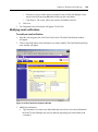
About the DSView 3.0 Explorer.................................................................................................. 8
Window features ......................................................................................................................... 8
Accessing units............................................................................................................................ 9
Configuring units ...................................................................................................................... 11
Unit icons.................................................................................................................................. 11
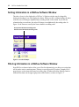
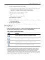
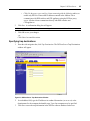
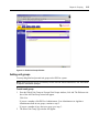
Sorting Information in a DSView Software Window ....................................................................... 12
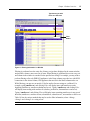
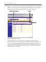
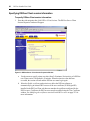
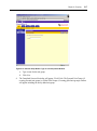
Filtering Information in a DSView Software Window..................................................................... 12
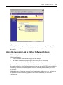
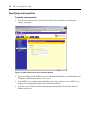
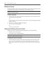
Saving Information in a DSView Software Window ........................................................................ 14
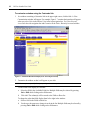
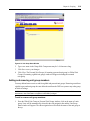
Using the Customize Link in DSView Software Windows ............................................................... 15
Viewing Pages.................................................................................................................................. 17
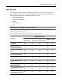
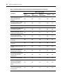
User Groups..................................................................................................................................... 19
User Preemption Levels................................................................................................................... 21
iv
DSView Installer/User Guide
Using Certificates with the DSView Software ................................................................................. 22
DSView Server certificate......................................................................................................... 22
DSView Client certificates........................................................................................................ 23
Managed appliance certificates................................................................................................ 23
Using Integrated Windows® Authentication with the DSView Software ........................................ 23
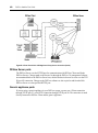
Using the DSView Software with a Firewall ................................................................................... 24
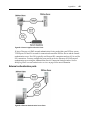
Using the DSView Software with a Virtual Private Network (VPN) ............................................... 25
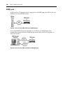
Using the DSView Software with a NAT Device.............................................................................. 26
Chapter 2: Installation ................................................................................................... 27
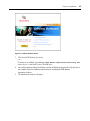
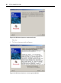
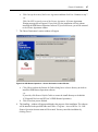
Installing the DSView 3.0 Management Software ........................................................................... 27
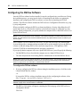
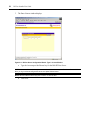
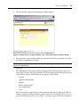
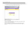
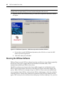
Configuring the DSView Software ................................................................................................... 36
Installing the DSR Remote Operations Software (Optional)........................................................... 43
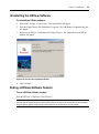
Running the DSView Software ......................................................................................................... 48
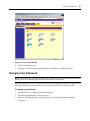
Changing the Color Scheme of the DSView 3.0 Explorer ............................................................... 50
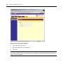
Changing Your Password ................................................................................................................ 51
Uninstalling the DSView Software .................................................................................................. 53
Ending a DSView Software Session................................................................................................. 53
Chapter 3: DSView Server ............................................................................................. 55
About the DSView Server................................................................................................................. 55
Setting up a DSView Server...................................................................................................... 56
Hub DSView Server Properties ....................................................................................................... 56
Specifying a DSView software proxy server............................................................................. 64
Specifying trap destinations...................................................................................................... 65
Specifying DSView Client session information ........................................................................ 66
Specifying email properties ...................................................................................................... 68
Using unit status polling........................................................................................................... 69
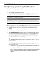
Manually Backing up and Restoring Hub DSView Servers............................................................. 70
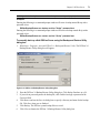
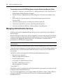
Managing Authentication Services .................................................................................................. 72
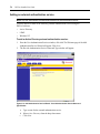
Adding an external authentication service ............................................................................... 74
Modifying authentication services............................................................................................ 87
Removing authentication services .......................................................................................... 103
Specifying and Managing Spoke Authentication Servers .............................................................. 103
Managing Licenses ........................................................................................................................ 113
Table of Contents
v
Displaying License Information..................................................................................................... 113
Displaying DSView software license keys .............................................................................. 113
Adding license keys................................................................................................................. 114
Managing servers ................................................................................................................... 114
Modifying Spoke DSView Server network settings................................................................. 116
Managing Hub and Spoke DSView Server certificates .......................................................... 117
Chapter 4: Managing Units.......................................................................................... 121
About Units .................................................................................................................................... 121
Using the Unit Views to display and modify units.................................................................. 122
Showing and hiding units ....................................................................................................... 126
Adding Units .................................................................................................................................. 130
Managing Units ............................................................................................................................. 147
Modifying unit overview information ..................................................................................... 147
Modifying unit properties ....................................................................................................... 150
Modifying unit access rights................................................................................................... 161
Modifying managed appliance settings .................................................................................. 165
Viewing active session information ........................................................................................ 213
Managing connections to units............................................................................................... 216
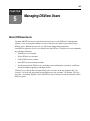
Chapter 5: Managing DSView Users .......................................................................... 225
About DSView Users...................................................................................................................... 225
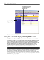
Using User Accounts to Display and Modify DSView users ......................................................... 226
Adding DSView Users.................................................................................................................... 229
Deleting DSView User Accounts ................................................................................................... 231
Unlocking DSView User Accounts ................................................................................................ 232
Resetting a DSView User Account Password ................................................................................ 232
Modifying DSView User Account Properties ................................................................................ 232
Modifying the names of DSView users ................................................................................... 233
Modifying the certificates associated with DSView users ...................................................... 233
Modifying DSView user passwords ........................................................................................ 234
Specifying account restrictions for DSView users.................................................................. 234
Changing DSView user group membership............................................................................ 235
Changing the preemption level of DSView users ................................................................... 235
Specifying address information for DSView users ................................................................. 235
Specifying phone contact information for DSView users ....................................................... 236
Table of Contents
vi
Specifying email contact information for DSView users ........................................................ 236
Creating DSView user notes................................................................................................... 237
Modifying DSView user custom field properties .................................................................... 237
Viewing the Access Rights of DSView Users ................................................................................. 237
Chapter 6: Using the Video Viewer Window.............................................................. 241
About the Video Viewer Window ................................................................................................... 241
Video Viewer window minimum requirements ....................................................................... 242
Launching a KVM session ............................................................................................................. 242
Launching an exclusive KVM session..................................................................................... 243
Connecting to an existing KVM session ................................................................................. 243
Window Features ........................................................................................................................... 245
Specifying Video Viewer session settings ...................................................................................... 247
Modifying the toolbar ............................................................................................................. 247
Toggling menu and toolbar activation ................................................................................... 248
Setting the Window Size ................................................................................................................. 248
Adjusting the View ......................................................................................................................... 249
Using background refresh ...................................................................................................... 250
Adjusting color depth.............................................................................................................. 251
Additional video adjustment ................................................................................................... 251
Image Capture Width, Pixel Sampling/Fine Adjust, Image Capture Horizontal Position and Image Capture Vertical Position ......................................................................................... 253
Contrast and Brightness ......................................................................................................... 253
Detection thresholds ............................................................................................................... 253
Block Noise Threshold and Pixel Noise Threshold ................................................................ 254
Automatic Video Adjustment................................................................................................... 254
Refresh Image ......................................................................................................................... 254
Video Test Pattern .................................................................................................................. 254
Adjusting Mouse Options............................................................................................................... 254
Cursor type ............................................................................................................................. 255
Single Cursor mode ................................................................................................................ 255
Cursor settings........................................................................................................................ 256
Scaling .................................................................................................................................... 256
Alignment................................................................................................................................ 257
Using Scan Mode ........................................................................................................................... 258
Table of Contents
vii
Thumbnail Viewer features..................................................................................................... 259
Performing Thumbnail Viewer tasks ...................................................................................... 260
Using Keyboard Pass-through....................................................................................................... 261
Using Global and Personal Macros .............................................................................................. 262
Power Controlling Target Devices ................................................................................................ 270
Displaying Video Viewer Window Users....................................................................................... 271
Saving the View.............................................................................................................................. 271
Closing a Video Viewer Window Session ...................................................................................... 272
Chapter 7: Using the Telnet/SSH Applet.................................................................... 273
About the Telnet/SSH Applet.......................................................................................................... 273
Telnet/SSH Applet Features........................................................................................................... 273
Telnet/SSH applet window toolbar ......................................................................................... 275
Security Property ........................................................................................................................... 276
Opening a Session.......................................................................................................................... 277
Customizing the Telnet/SSH Applet ............................................................................................... 277
Changing Colors............................................................................................................................ 278
Changing the Cursor ..................................................................................................................... 278
Customizing Session Properties..................................................................................................... 278
Changing the terminal window size........................................................................................ 279
Changing the Terminal Emulation mode................................................................................ 279
Changing Arrow key sequences.............................................................................................. 279
Changing the terminal type .................................................................................................... 280
Changing the linefeed settings................................................................................................ 281
Enabling and disabling line wrap .......................................................................................... 281
Enabling and disabling local echo ......................................................................................... 282
Enabling and disabling 7-bit ASCII ....................................................................................... 282
Login scripts ........................................................................................................................... 282
Telnet/SSH Applet History Mode ................................................................................................... 283
Macros ........................................................................................................................................... 285
Logging .......................................................................................................................................... 289
Log files .................................................................................................................................. 289
Copying, Pasting and Printing Session Data ................................................................................ 292
Power Controlling Target Devices (Serial Session Only) ............................................................. 293
Closing a Telnet Appliance Session............................................................................................... 294
Table of Contents
viii
Chapter 8: Grouping .................................................................................................... 295
About Grouping ............................................................................................................................. 295
Managing Units Using Sites .......................................................................................................... 296
Viewing, adding, modifying and deleting sites ....................................................................... 298
Displaying units associated with sites .................................................................................... 301
Associating, changing or removing the association of units with a site................................. 302
Managing Units Using Departments ............................................................................................. 303
Viewing, adding, modifying and deleting departments .......................................................... 304
Associating, changing or removing the association of units with
a department.................................................................................................................... 307
Managing Units Using Locations .................................................................................................. 308
Viewing, adding, modifying and deleting locations ............................................................... 309
Associating, changing or removing the association of units with a location ......................... 312
Managing Units using Unit Groups............................................................................................... 313
Adding unit groups ................................................................................................................. 315
Deleting unit groups ............................................................................................................... 318
Viewing and modifying unit group members .......................................................................... 318
Adding and removing unit group members ............................................................................ 319
Using Groups to view and modify units.................................................................................. 322
Managing Units using Custom Fields ........................................................................................... 323
Managing DSView Users using User Groups ............................................................................... 329
Adding user-defined user groups............................................................................................ 332
Deleting user-defined user groups.......................................................................................... 338
Viewing and modifying user group members ......................................................................... 339
Chapter 9: Using DSView 3.0 Management Software Tools .................................... 347
About Tools .................................................................................................................................... 347
Using Unit Tools ............................................................................................................................ 347
Exporting units ....................................................................................................................... 348
Exporting unit rights............................................................................................................... 351
Merging target devices ........................................................................................................... 354
Using DSR Switch and CPS Appliance Tools................................................................................ 356
Rebooting DSR switches and CPS appliances........................................................................ 357
Upgrading the firmware on DSR switches and CPS appliances............................................ 358
Resynchronizing DSR switches and CPS appliances ............................................................. 360
Table of Contents
ix
Saving the configuration of DSR switches and CPS appliances ............................................ 363
Restoring the configuration of DSR switches and CPS appliances........................................ 364
Saving the user database of a DSR switch or CPS appliance ................................................ 365
Restoring the user database of a DSR switch or CPS appliance ........................................... 366
Managing Tasks ............................................................................................................................. 368
Adding tasks............................................................................................................................ 369
Specifying when to run tasks................................................................................................... 371
Adding tasks using the Add Task Wizard................................................................................ 378
Running tasks manually.......................................................................................................... 393
Deleting tasks.......................................................................................................................... 393
Modifying tasks....................................................................................................................... 394
Firmware Management.................................................................................................................. 395
Adding firmware ..................................................................................................................... 396
Displaying or modifying firmware information...................................................................... 397
Deleting firmware................................................................................................................... 399
Chapter 10: Working with Audit Logs ........................................................................ 401
About Audit Logs ........................................................................................................................... 401
DSView software events.......................................................................................................... 404
Viewing Audit Logs ........................................................................................................................ 408
Using the Date Filter ..................................................................................................................... 410
Viewing the Details of Audit Log Events ....................................................................................... 412
Deleting Audit Log Events ............................................................................................................. 413
Enabling and Disabling Audit Log Events .................................................................................... 413
Retaining the Audit Log .......................................................................................................... 415
Configuring Email Notifications.................................................................................................... 416
Modifying email notifications ................................................................................................. 419
Deleting email notifications.................................................................................................... 420
Testing email notifications...................................................................................................... 421
Using the Audit Log Tool............................................................................................................... 421
Table of Contents
x
Appendices................................................................................................................... 425
Appendix A: Technical Support ..................................................................................................... 425
Appendix B: TCP Ports.................................................................................................................. 426
Appendix C: DSR Remote Operations Software............................................................................ 433
Appendix D: Terminal Emulation.................................................................................................. 444
Chapter 1: Glossary ..................................................................................................... 459
Index.............................................................................................................................. 471
xi
LIST OF FIGU RES
List of Figures
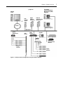
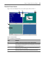
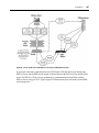
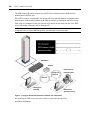
Figure 1.1: Example System Configuration Using the DSView Software ......................................... 7
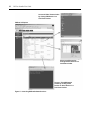
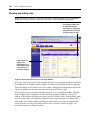
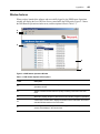
Figure 1.2: DSView 3.0 Explorer Window ........................................................................................ 8
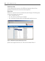
Figure 1.3: Launching DSView Software Sessions ......................................................................... 10
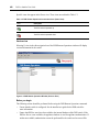
Figure 1.4: List Sort Example.......................................................................................................... 12
Figure 1.5: Filtering Information in a Window............................................................................... 13
Figure 1.6: Unsaved Window Example ........................................................................................... 15
Figure 1.7: Customize Window Example (Units - Recently Accessed) ........................................... 16
Figure 1.8: Viewing Pages in a Window ......................................................................................... 18
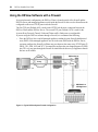
Figure 1.9: Typical DSView System Firewall Configuration.......................................................... 24
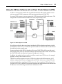
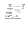
Figure 1.10: DSView System on a VPN........................................................................................... 25
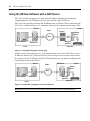
Figure 1.11: Single NAT Configuration (Client Only) .................................................................... 26
Figure 1.12: Double-NAT Configuration (Client and Corporate) .................................................. 26
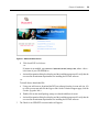
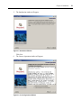
Figure 2.1: DSView Software Screen .............................................................................................. 29
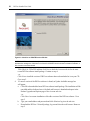
Figure 2.2: Check for an UPDATED version Window ................................................................... 30
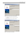
Figure 2.3: Introduction Window .................................................................................................... 31
Figure 2.4: License Agreement Window.......................................................................................... 31
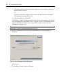
Figure 2.5: Define Web Application Server TCP Port Window...................................................... 32
Figure 2.6: Define TD Session Viewer Proxy TCP Port Window ................................................... 33
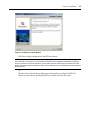
Figure 2.7: Choose Destination Location Window ......................................................................... 33
Figure 2.8: Successful Service Startup Message Box...................................................................... 34
Figure 2.9: Installation Complete Window ..................................................................................... 35
Figure 2.10: DSView Server Configuration Wizard - Select DSView Server Role Window ........... 37
Figure 2.11: DSView Server Configuration Wizard - Type in License Window ............................. 38
Figure 2.12: DSView Server Configuration Wizard - Type in Initial
Administrator Information Window.......................................................................................... 39
Figure 2.13: User Login Window .................................................................................................... 40
Figure 2.14: DSView Server Configuration Wizard - Type in Hub Server
Address and Port Window ........................................................................................................ 41
Figure 2.15: DSView Server Configuration Wizard - Accept DSView Server
Certificate Window ................................................................................................................... 42
Figure 2.16: DSView Server Configuration Wizard - Type in Hub Administrator
Credentials Window ................................................................................................................. 43
xii
DSView Installer/User Guide
Figure 2.17: DSView Software Screen ............................................................................................ 45
Figure 2.18: DSR Remote Operations - Introduction Window ....................................................... 46
Figure 2.19: DSR Remote Operations - License Agreement Window ............................................. 46
Figure 2.20: DSR Remote Operations - Choose Destination Location Window............................. 47
Figure 2.21: DSR Remote Operations - DSR Remote Operations Installation Window................. 48
Figure 2.22: User Login Window .................................................................................................... 50
Figure 2.23: Color Scheme Window................................................................................................ 51
Figure 2.24: Change Password Window ......................................................................................... 52
Figure 2.25: Uninstall Avocent DSView Window ........................................................................... 53
Figure 3.1: DSView Server Identification Properties Window ....................................................... 58
Figure 3.2: DSView Server Network Properties Window ............................................................... 59
Figure 3.3: DSView Server Certificate Properties Window............................................................ 60
Figure 3.4: Update DSView Server Certificate Wizard - Select Option to Perform Window ......... 61
Figure 3.5: Update DSView Server Certificate Wizard - Type in Certificate
Information Window ................................................................................................................. 62
Figure 3.6: Update DSView Server Certificate Wizard - Select Certificate to Import Window ..... 63
Figure 3.7: DSView Server Proxy Properties Window ................................................................... 64
Figure 3.8: DSView Server Trap Destinations Window.................................................................. 65
Figure 3.9: DSView Server Client Session Properties Window ...................................................... 66
Figure 3.10: DSView Server Email Server Properties Window ...................................................... 68
Figure 3.11: DSView Server Unit Status Polling Properties Window ............................................ 69
Figure 3.12: DSView 3.0 Backup/Restore Utility Dialog Box ........................................................ 71
Figure 3.13: User Authentication Services Window ....................................................................... 73
Figure 3.14: Add Authentication Service Wizard - Provide Authentication Service
Name and Type Window ........................................................................................................... 74
Figure 3.15: Add Authentication Service Wizard - Specify Active Directory
Connection Settings Window .................................................................................................... 75
Figure 3.16: Add Authentication Service Wizard - Accept Certificate Window ............................. 76
Figure 3.17: Add Authentication Service Wizard - Select Browsing Method Window ................... 77
Figure 3.18: Add Authentication Service Wizard - Provide Authentication Service
Name and Type Window ........................................................................................................... 78
Figure 3.19: Add Authentication Service Wizard - Specify Windows NT Connection
Settings Window ....................................................................................................................... 79
Figure 3.20: Add Authentication Service Wizard - Select Browsing Method Window ................... 80
List of Figures
xiii
Figure 3.21: Add Authentication Service Wizard - Provide Authentication Service
Name and Type Window ........................................................................................................... 81
Figure 3.22: Add Authentication Service Wizard - Specify LDAP Connection Settings Window... 82
Figure 3.23: Add Authentication Service Wizard - Accept Certificate Window ............................. 83
Figure 3.24: Add Authentication Service Wizard - Specify LDAP User Schema Window.............. 84
Figure 3.25: Add Authentication Service Wizard - LDAP Group Schema Window........................ 85
Figure 3.26: Add Authentication Service Wizard - Select Browsing Method Window ................... 86
Figure 3.27: Authentication Service User Account Policies - DSView Internal Window ............... 87
Figure 3.28: Authentication Service User Account Custom Field Labels - DSView
Internal Window ....................................................................................................................... 89
Figure 3.29: Authentication Service Connection Settings - NT Window ........................................ 90
Figure 3.30: Authentication Service User Browsing - NT Window ................................................ 91
Figure 3.31: Authentication Service Connection Settings - AD Window ........................................ 92
Figure 3.32: Authentication Service Certificate Management - AD Window ................................. 93
Figure 3.33: Accept SSL Certificate Window .................................................................................. 94
Figure 3.34: Authentication Service User Browsing - AD Window ................................................ 95
Figure 3.35: Authentication Service Connection Settings - LDAP Window ................................... 97
Figure 3.36: Authentication Service Certificate Management - LDAP Window ............................ 98
Figure 3.37: Accept SSL Certificate Window .................................................................................. 99
Figure 3.38: Authentication Service User Schema - LDAP Window ............................................ 100
Figure 3.39: Authentication Service Group Schema - LDAP Window.......................................... 101
Figure 3.40: Authentication Service User Browsing - LDAP Window ......................................... 102
Figure 3.41: Spoke Servers Window.............................................................................................. 105
Figure 3.42: DSView Server Tools Window .................................................................................. 107
Figure 3.43: Register Spoke Server Wizard - Type in Hub DSView Server Address Window ...... 108
Figure 3.44: Register Spoke Server Wizard - Accept Hub DSView Server Certificate Window... 109
Figure 3.45: Type in Hub DSView Server Administrator Credentials Window ............................ 110
Figure 3.46: Spoke Server Network Properties Window............................................................... 111
Figure 3.47: Spoke Servers Window.............................................................................................. 112
Figure 3.48: Spoke Server Network Properties Window............................................................... 116
Figure 3.49: DSView Server Certificate Properties Window........................................................ 118
Figure 3.50: Hub Server Certificate Window................................................................................ 119
Figure 4.1: Target Devices - All Window...................................................................................... 122
Figure 4.2: Appliances - All Window ............................................................................................ 124
Figure 4.3: Target Devices - All Window...................................................................................... 125
List of Figures
xiv
Figure 4.4: Shown and Hidden Units in a Unit Views Window .................................................... 126
Figure 4.5: Add Unit Wizard - Select Add Unit Procedure Window............................................. 132
Figure 4.6: Add Unit Wizard - Select Appliance Type Window .................................................... 133
Figure 4.7: Add Unit Wizard - Select Address Configuration of Appliance Window ................... 134
Figure 4.8: Add Unit Wizard - Configure Appliance Network Settings Window .......................... 135
Figure 4.9: Add Unit Wizard - Select Options Window ................................................................ 136
Figure 4.10: Add Unit Wizard - Configure Cascade Switches Window........................................ 137
Figure 4.11: Add Unit Wizard - Select Add Unit Procedure Window........................................... 138
Figure 4.12: Add Unit Wizard - Type in Discover IP Address Range Window ............................ 139
Figure 4.13: Add Unit Wizard - Select Appliances to Add Window.............................................. 140
Figure 4.14: Add Unit Wizard - Select Options Window .............................................................. 141
Figure 4.15: Add Unit Wizard - Select Add Unit Procedure Window........................................... 142
Figure 4.16: Add Unit Wizard - Select Appliance Type Window .................................................. 143
Figure 4.17: Add Unit Wizard - Configure Generic Appliance Settings Window......................... 144
Figure 4.18: Select Add Unit Procedure Window ......................................................................... 145
Figure 4.19: Type in Device Settings Window .............................................................................. 146
Figure 4.20: Unit Overview Window (Target Devices)................................................................. 148
Figure 4.21: Unit Overview Window (DSR Switches and CPS Appliances)................................. 149
Figure 4.22: Unit Overview Window (DSR Switches and CPS Appliances)................................. 151
Figure 4.23: Unit Identification Properties Window..................................................................... 152
Figure 4.24: Unit Location Properties Window ............................................................................ 154
Figure 4.25: Unit Contacts Window.............................................................................................. 155
Figure 4.26: Unit Custom Fields Window..................................................................................... 156
Figure 4.27: Unit Notes Window ................................................................................................... 157
Figure 4.28: Unit Network Properties (Target Device) ................................................................ 158
Figure 4.29: Unit Network Properties Window (DSR Switches and CPS Appliances)................. 159
Figure 4.30: Unit Network Properties Window (Generic Appliances) ......................................... 160
Figure 4.31: Unit Access Rights Window (Target Devices) .......................................................... 161
Figure 4.32: Unit Access Rights Window (DSR Switches and CPS Appliances) .......................... 162
Figure 4.33: Unit Access Rights User Selection Window ............................................................. 163
Figure 4.34: Appliance Network Settings WIndow (DSR Switch)................................................. 166
Figure 4.35: Appliance Authentication Servers Settings Window................................................. 167
Figure 4.36: Appliance SNMP System Settings Window............................................................... 169
Figure 4.37: Appliance SNMP Manager Settings Window ........................................................... 170
Figure 4.38: Appliance SNMP Community Settings Window ....................................................... 171
List of Figures
xv
Figure 4.39: Appliance SNMP Destination Settings Window ....................................................... 172
Figure 4.40: Appliance SNMP Trap Settings Window .................................................................. 173
Figure 4.41: Appliance Version Information Window (DSR Switch)............................................ 174
Figure 4.42: Appliance IQ Modules Window ................................................................................ 175
Figure 4.43: Appliance Cascade Switches Window ...................................................................... 177
Figure 4.44: Appliance OSCAR Settings Window......................................................................... 178
Figure 4.45: Appliance Modem Settings Window ......................................................................... 179
Figure 4.46: SPC Devices Attached to Appliance Window........................................................... 180
Figure 4.47: SPC Settings Window ............................................................................................... 183
Figure 4.48: SPC Sockets Window ................................................................................................ 184
Figure 4.49: SPC Socket Settings Window .................................................................................... 185
Figure 4.50: Appliance Serial Ports Window................................................................................ 187
Figure 4.51: Appliance Serial Port General Settings Window ..................................................... 188
Figure 4.52: Appliance Serial Ports Communications Settings Window ...................................... 190
Figure 4.53: Appliance CLI Port Settings Window ....................................................................... 192
Figure 4.54: Appliance CLI PPP Settings Window....................................................................... 193
Figure 4.55: Appliance Sessions Window ..................................................................................... 196
Figure 4.56: Active Session Information Window ......................................................................... 197
Figure 4.57: Appliance Settings - Sessions - Settings Window (CPS Appliance) ......................... 198
Figure 4.58: Appliance Settings - Sessions - Settings Window (DSR Switch)............................... 199
Figure 4.59: Appliance Exit Macros Window ............................................................................... 201
Figure 4.60: Appliance Exit Macro Settings Window ................................................................... 202
Figure 4.61: Entering the Macro Name ........................................................................................ 203
Figure 4.62: The Completed Macro .............................................................................................. 204
Figure 4.63: Appliance Local User Accounts Window ................................................................. 205
Figure 4.64: Add Local User Account Wizard - Type in Local User Credentials Window .......... 206
Figure 4.65: Add Local User Account Wizard - Select Preemption Level Window ...................... 207
Figure 4.66: Add Local User Account Wizard - Select Access Level Window.............................. 208
Figure 4.67: Add Local User Account Wizard - Assign Target Devices Window......................... 209
Figure 4.68: Appliance Local User Account Settings Window ..................................................... 211
Figure 4.69: Appliance Local User Account Access Rights Window............................................ 212
Figure 4.70: Active Sessions Window............................................................................................ 214
Figure 4.71: Active Session Information Window ......................................................................... 215
Figure 4.72: Target Device Connections Window ........................................................................ 216
Figure 4.73: Appliance Connections Window ............................................................................... 217
List of Figures
xvi
Figure 4.74: Appliance Connections Window (Target Device) .................................................... 219
Figure 4.75: Appliance Connections Window (Appliance) ........................................................... 220
Figure 4.76: Appliance Connections - Rename Window............................................................... 221
Figure 4.77: Add Target Device Connection Wizard - Select Connection Type Window............. 222
Figure 4.78: Add Target Device Connection Wizard - Select Appliance with
Available Ports Window (KVM Connection Type Shown) ..................................................... 223
Figure 4.79: Add Target Device Connection Wizard - Select Available
Connection Window (KVM Connection Type Shown)............................................................ 224
Figure 5.1: User Accounts - All Window....................................................................................... 226
Figure 6.1: Video Viewer Window (Normal Window Mode) ........................................................ 245
Figure 6.2: Manual Video Adjust Dialog Box ............................................................................... 252
Figure 6.3: Video Viewer Window with Local and Remote Cursors Displayed ........................... 255
Figure 6.4: Thumbnail Viewer....................................................................................................... 259
Figure 7.1: Telnet/SSH Applet Window......................................................................................... 274
Figure 8.1: Displaying Sites .......................................................................................................... 297
Figure 8.2: Sites Window............................................................................................................... 299
Figure 8.3: Add Site Window......................................................................................................... 300
Figure 8.4: Site Name Window...................................................................................................... 301
Figure 8.5: Example Units in Site Window ................................................................................... 302
Figure 8.6: Departments Window ................................................................................................. 305
Figure 8.7: Add Department Window............................................................................................ 306
Figure 8.8: Department Name Window......................................................................................... 307
Figure 8.9: Locations Window ...................................................................................................... 310
Figure 8.10: Add Location Window .............................................................................................. 311
Figure 8.11: Location Name Window............................................................................................ 312
Figure 8.12: Personal Unit Groups Window................................................................................. 314
Figure 8.13: Global Unit Groups Window .................................................................................... 315
Figure 8.14: Add Unit Group Wizard - Select Unit Group Type Window .................................... 316
Figure 8.15: Add Unit Group Wizard - Type in Unit Group Name Window ................................ 317
Figure 8.16: Unit Group Name Window ....................................................................................... 319
Figure 8.17: Unit Group Members Window.................................................................................. 320
Figure 8.18: Assign Units to Unit Group Window ........................................................................ 321
Figure 8.19: Units in Group Window ............................................................................................ 323
Figure 8.20: Units in Custom Field Window................................................................................. 324
Figure 8.21: Unit Custom Field Labels Window........................................................................... 325
List of Figures
xvii
Figure 8.22: Unit Custom Fields Window..................................................................................... 326
Figure 8.23: Custom Fields Example: Unit Custom Fields Window ............................................ 328
Figure 8.24: Custom Fields Example: Side Navigation Bar ......................................................... 329
Figure 8.25: User Groups - Built-in Window................................................................................ 331
Figure 8.26: User Groups - User Defined Window....................................................................... 332
Figure 8.27: Add User Group Wizard - Select Authentication Service Window........................... 333
Figure 8.28: Add User Group Wizard - Type in Internal Group Name Window .......................... 334
Figure 8.29: Add User Group Window - Specify External Group
Name Window (LDAP and Active Directory)......................................................................... 335
Figure 8.30: Add User Account Wizard - Select Group from External
Authentication Service Window.............................................................................................. 336
Figure 8.31: Add User Group Wizard - Select Role Window........................................................ 337
Figure 8.32: Add User Group Wizard - Select User Group Preemption Level Window .............. 338
Figure 8.33: User Group Properties Window ............................................................................... 340
Figure 8.34: User Group Members Window ................................................................................. 342
Figure 8.35: Assign Users to User Group Window....................................................................... 343
Figure 8.36: Target Devices Access Rights Window..................................................................... 345
Figure 8.37: Appliance Access Rights Window............................................................................. 346
Figure 9.1: Units Tools Window.................................................................................................... 348
Figure 9.2: Export Units Wizard - Select Unit Properties to Export Window .............................. 350
Figure 9.3: Export Unit Rights Wizard - Select Unit Type Window.............................................. 353
Figure 9.4: Merge Target Devices Wizard - Select Target Devices to Merge Window ................ 354
Figure 9.5: Merge Target Devices Wizard - Confirm Target Device Merge Window .................. 355
Figure 9.6: Unit Overview Window............................................................................................... 357
Figure 9.7: Upgrade Appliance Firmware Wizard - Select Firmware Files Window .................. 358
Figure 9.8: Upgrade Appliance Firmware Wizard - Type in Task Name Window ....................... 359
Figure 9.9: Resync Appliance Wizard - Select Resync Options Window ...................................... 360
Figure 9.10: Resync Appliance Wizard - Changes Detected in Appliance Window ..................... 361
Figure 9.11: Resync Appliance Wizard - Cascade Switch Configuration Window....................... 362
Figure 9.12: Save Appliance Configuration Wizard - Type in File Description Window............. 364
Figure 9.13: Restore Appliance Configuration Wizard - Select Configuration
to Restore Window.................................................................................................................. 365
Figure 9.14: Save Appliance User Database Wizard - Type in File Description Window ........... 366
Figure 9.15: Restore Appliance User Database Wizard - Select User Database
to Restore Window.................................................................................................................. 367
List of Figures
xviii
Figure 9.16: Tasks Window ........................................................................................................... 368
Figure 9.17: Select Task to Add Window ...................................................................................... 370
Figure 9.18: Add Task Wizard - Select When to Run Task Window ............................................. 372
Figure 9.19: Add Task Wizard - Specify Periodic Schedule Window ........................................... 373
Figure 9.20: Add Task Wizard - Specify Daily Schedule Window ................................................ 374
Figure 9.21: Add Task Wizard - Specify Weekly Schedule Window.............................................. 376
Figure 9.22: Add Task Wizard - Specify Monthly Schedule Window ............................................ 377
Figure 9.23: Add Task Wizard - Specify DSView System Backup Properties Window................. 379
Figure 9.24: Add Task Wizard - Select Unit Group Window ........................................................ 380
Figure 9.25: Add Task Wizard - Select Appliance Type Window.................................................. 381
Figure 9.26: Add Task Wizard - Select Appliances Window ......................................................... 382
Figure 9.27: Add Task Wizard - Configure SNMP Traps Window ............................................... 383
Figure 9.28: Add Task Wizard - Select Unit Group Window ........................................................ 384
Figure 9.29: Add Task Wizard - Select Target Devices Window .................................................. 385
Figure 9.30: Add Task Wizard - Select Power Control Function Window ................................... 386
Figure 9.31: Add Task Wizard - Specify Export Audit Log Properties Window ........................... 387
Figure 9.32: Add Tasks Window - Select Audit Log Columns to Export Window ........................ 388
Figure 9.33: Add Task Wizard - Select Unit Group Window ........................................................ 390
Figure 9.34: Add Task Wizard - Select Appliance Type Window.................................................. 391
Figure 9.35: Add Task Wizard - Select Appliances Window ......................................................... 392
Figure 9.36: Task Schedule Window ............................................................................................. 394
Figure 9.37: Appliance Firmware Files Window .......................................................................... 395
Figure 9.38: Add Firmware File Wizard- Select Firmware File to Import Window .................... 397
Figure 9.39: Firmware File Properties Window........................................................................... 398
Figure 10.1: Audit Log - All Window ............................................................................................ 402
Figure 10.2: Date Filter Window .................................................................................................. 410
Figure 10.3: Audit Log - All Window with Clear Date Filter Button............................................ 411
Figure 10.4: Audit Log Event Information Window ...................................................................... 412
Figure 10.5: Enabled Audit Log Events Window .......................................................................... 414
Figure 10.6: Audit Log Retention Time Window ........................................................................... 415
Figure 10.7: Email Notifications Window ..................................................................................... 416
Figure 10.8: Add Email Notification Wizard - Specify Email Properties Window ....................... 417
Figure 10.9: Select Events to Trigger Email Notification Window ............................................... 418
Figure 10.10: Email Notification Properties Window................................................................... 419
Figure 10.11: Audit Log Tools Window ........................................................................................ 422
List of Figures
xix
Figure 10.12: Export Audit Log Wizard - Select Columns to Export Window.............................. 423
Figure B.1: Ports Used with a DSR Switch Connection (KVM) Without Proxy ........................... 427
Figure B.2: Ports Used with a DSR Switch Proxy Server Connection (KVM) ............................. 428
Figure B.3: Ports Used with A CPS Appliance Connection (Serial) Without Proxy .................... 429
Figure B.4: Ports Used with A CPS Appliance Proxy Server Connection (Serial)....................... 430
Figure B.5: Generic Appliance Session Ports ............................................................................... 431
Figure B.6: External Authentication Server Ports ........................................................................ 431
Figure B.7: Ports Used by SNMP (No External SNMP Manager) ............................................... 432
Figure B.8: Ports Used by SNMP (with External SNMP Manager) ............................................. 432
Figure C.1: Using the DSR Remote Operations Software with a DSR Switch.............................. 434
Figure C.2: DSR Remote Operations Window .............................................................................. 435
Figure C.3: DSR Remote Operations Window (Servers View) ..................................................... 436
Figure C.4: DSR Remote Operations Window (Power View) ....................................................... 437
Figure C.5: DSR Remote Operations Window (Versions View) ................................................... 438
Figure C.6: Login Dialog Box ....................................................................................................... 439
Figure C.7: DSR Remote Operations Window .............................................................................. 440
List of Figures
xx
xxi
LIST OF TABLES
List of Tables
Table 1.1: DSView 3.0 Explorer Window Area Descriptions............................................................ 9
Table 1.2: DSView 3.0 Explorer Window Links ................................................................................ 9
Table 1.3: Managed Appliance Icons .............................................................................................. 11
Table 1.4: Filter Field Text Strings ................................................................................................. 14
Table 1.5: DSView 3.0 Explorer Navigation Buttons ...................................................................... 17
Table 1.6: DSView Software Built-in User Groups and Allowed Operations................................. 19
Table 1.7: DSView User and User Group Preemption Levels ........................................................ 21
Table 1.8: Built-In User Group Preemption Levels ........................................................................ 22
Table 3.1: Spoke DSView Server Status Icons............................................................................... 105
Table 4.1: Unit Icons ..................................................................................................................... 128
Table 4.2: Actions to Initiate DSView Sessions ............................................................................. 129
Table 5.1: DSView User Status Icons ............................................................................................ 227
Table 6.1: Video Viewer Window Descriptions............................................................................. 246
Table 6.2: Manual VIdeo Adjust Dialog Box Descriptions ........................................................... 253
Table 6.3: Thumbnail Viewer Descriptions ................................................................................... 259
Table 7.1: Telnet/SSH Applet Window Descriptions ..................................................................... 274
Table 7.2: Telnet/SSH Applet Window Toolbar Icons ................................................................... 275
Table 7.3: Arrow Key Sequences ................................................................................................... 280
Table 0.1: Terminal Emulation and Type ...................................................................................... 281
Table 8.1: Windows Containing a Site Column............................................................................. 298
Table 8.2: Links for Add, Changing or Removing Site Association .............................................. 303
Table 8.3: Windows Containing a Department Column................................................................ 304
Table 8.4: Links for Adding, Changing or Removing Department Association ............................ 308
Table 8.5: Windows Containing a Location Column .................................................................... 309
Table 8.6: Links for Adding, Changing or Removing Location Association ................................. 313
Table 9.1: Task Status Icons .......................................................................................................... 369
xxii
DSView Installer/User Guide
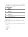
Table 10.1: Audit Log Severity Icons............................................................................................. 403
Table 10.2: DSView Software Appliance Events ........................................................................... 404
Table 10.3: DSView System Events ............................................................................................... 405
Table 10.4: DSView Software Authentication Events.................................................................... 406
Table 10.5: DSView Software User and User Group Events ........................................................ 406
Table 10.6: DSView Software Unit Events .................................................................................... 406
Table 10.7: DSView Software Task Events.................................................................................... 407
Table 10.8: DSView Software Unit Status Events ......................................................................... 407
Table 10.9: DSView Software Access Control Events ................................................................... 407
Table 10.10: DSView Software Session Events ............................................................................. 408
Table C.1: DSR Remote Operations Descriptions......................................................................... 435
Table C.2: DSR Remote Operations Content Area Icons (Servers View) ..................................... 437
Table C.3: DSR Remote Operations Content Area Icons (Power View)....................................... 438
Table D.1: VT Key and Keypad Numeric Codes ........................................................................... 444
Table D.2: VT100+ Function Key Support ................................................................................... 445
Table D.3: VT102 Receive Codes .................................................................................................. 445
Table D.4: VT100 Special Keys and Control Keys........................................................................ 446
Table D.5: VT100 ANSI Set and Reset Mode Cursor Keys ........................................................... 447
Table D.6: VT100 PF1-PF4 Key Definitions ................................................................................ 448
Table D.7: VT100 ANSI Mode Control Sequences........................................................................ 448
Table D.8: VT220 Encoding .......................................................................................................... 452
Table D.9: VT220 Decoding .......................................................................................................... 453
Table D.10: VT52 Encoding .......................................................................................................... 454
Table D.11: VT52 Decoding .......................................................................................................... 454
Table D.12: VT52 ANSI Mode Auxiliary Keypad Definitions ....................................................... 455
Table D.13: VT320 Encoding ........................................................................................................ 456
Table D.14: VT320 Decoding ........................................................................................................ 457
1
CHAPTER
1
Product Overview
About the DSView 3.0 Management Software
The DSView® 3.0 software is a secure, web browser based, centralized enterprise management
solution that allows DSView users to remotely access, manage, monitor and control target devices
through the following types of Avocent managed appliances:
•
DSR™ switches
•
CPS serial over IP network appliances
Other managed appliances (EVR1500 environmental monitor and control appliances and generic
appliances), Cascade switches and SPC power control devices may also be included, viewed and
controlled in the DSView software. A session may be launched to a target device with a single
point of access.
A DSView Administrator may specify DSView users and their access levels for commands within
the system, as well as group them in various ways.
Features and Benefits
Network rebooting and troubleshooting
The DSView software uses industry standard IP connections so that you can easily troubleshoot, or
even reboot a server, from the Network Operations Center (NOC), from your desk or from any
location in the world. With the DSView software, you can access all of your data center devices
from a single screen - making complex network access and control remarkably easy.
Web-based access and control
The DSView software provides secure “point-and-click” web browser based access to control
virtually any data center device using DSR switches and CPS appliances from DSView Clients that
may be located anywhere in the world.
The DSView software supports Microsoft® Internet Explorer version 6.0 SP1 and later.
NOTE: It is recommended that Microsoft Internet Explorer is kept up to date with the latest updates
from Microsoft.
2
DSView Installer/User Guide
A Video Viewer window allows you to control the keyboard, monitor and mouse functions of
individual target devices connected to a DSR switch in real time. You may also use predefined
global macros to perform actions within the Video Viewer window, or create new macros within
the window for the device. The Video Viewer window may be launched by clicking KVM Session
in a DSView 3.0 Explorer Unit Views window for any target device, or clicking KVM Session or
Exclusive KVM Session (none-shared) in the Unit Overview window for the target device.
Devices connected to a CPS appliance may be accessed using a Telnet/SSH applet window.
Secure authentication and communication
Secure Socket Layer (SSL) encryption may be used to encrypt data traveling within the DSView
system. DSView users may be authenticated using the DSView Server internal database, or using a
Lightweight Directory Assistance Protocol (LDAP), Active Directory® or Windows NT® domain
external authentication server.
Creating and managing user permissions
The DSView software provides centralized network access, control and security for managed
appliances. A DSView Administrator may add, remove, delete and modify managed appliances and
target devices, including assigning permissions and per-device contact information, which are
stored on the DSView Server. A DSView Administrator may also assign unique permissions which
allow individual DSView users or a group of DSView users access to units.
DSView users may be authenticated using the local DSView internal database or by an
external server.
Proxy server access
The DSView software also contains a proxy server feature that allows KVM and Serial Sessions to
be proxied through the DSView Server. When a session is initiated with a target device, the Video
Viewer communicates using the Avocent Proxy Protocol (APP) and the DSView Server makes a
direct connection to the appliance. See Hub DSView Server Properties on page 56 for information
on specifying a proxy server.
DSView System Components
The following components comprise a DSView system:
DSView software
The DSView software resides on the DSView Server (host computer) and provides a web gateway
and services for managing units (managed appliances and target devices) using a web browser. The
gateway allows for IP-based video, serial management, Telnet SSH applet or web browser sessions.
DSView users may connect to the DSView Server from DSView Clients and use the DSView 3.0
Explorer window to communicate with the system.
Chapter 1: Product Overview
3
DSView Server
A DSView Server is the computer on which the DSView software is installed. The DSView Server
provides a central repository for the following information:
•
Centralized authentication
•
Access control
•
Auditing
•
Monitoring
•
License management
•
DSView Client/appliance updates
DSView users may specify a Spoke (backup) DSView Server in addition to the Hub
DSView Server.
DSView Client
A DSView Client is a computer with an Internet Explorer version 6.0 SP1 or later web browser that
may access the DSView software installed on the DSView Server. A DSView user may access and
administer the DSView Server, units and cascade devices using the DSView Client.
Managed appliances
Managed appliances are DSR switches and CPS appliances that provide KVM and Serial Over IP
connectivity to a wide range of target devices, EVR1500 environmental monitors and
generic appliances.
Target devices
Target devices encompass a wide range of data center components such as servers and routers that
a DSView Administrator may manage virtually through the DSView system. A target device may
be attached to a DSR switch or CPS appliance and is added automatically to your DSView system
when the DSR switch or CPS appliance is added, or added individually when not attached to a DSR
switch or CPS appliance.
Cascade devices
A cascade device is connected between a DSR switch or CPS appliance and a target device, or
directly to the DSR switch or CPS appliance. Examples of cascade devices are AutoView® cascade
switches, Outlook® cascade switches and SPC devices.
4
DSView Installer/User Guide
External authentication server (optional)
The External authentication server is a third-party product that may be configured for use within
your DSView system. The external authentication server provides an authentication service that
enables the DSView Server to broker authentication requests from DSView users for access to the
DSView System.
SNMP manager (optional)
The SNMP manager is a third-party product that may be configured for use within your DSView
system. The SNMP manager monitors DSR switches and CPS appliances and receives SNMP traps
from the DSView software on the DSView Server.
An example of an SNMP manager is the HP OpenView product.
Appliances Supported by the DSView Software
The following appliances may be controlled and managed using the DSView software:
Managed appliances
A managed appliance may provide KVM and serial over IP connectivity to target devices. The
DSView software supports the following types of managed appliances that support
this connectivity:
•
CPS appliances
•
DSR switches
Managed appliances also include the following:
•
EVR1500 environmental monitors
•
Generic appliances
CPS appliances
CPS appliances allow DSView users to access serially attached devices over a standard TCP/IP
connection using a Telnet/SSH applet. The DSView Server discovers CPS appliances on the
DSView system.
The DSView software supports the following CPS appliances:
•
CPS810
•
CPS1610
Chapter 1: Product Overview
5
DSView Clients communicate with target device serial ports using a Telnet SSH connection
between the DSView Client and the CPS. The CPS converts the Telnet data to a serial stream,
which is then sent to the Target Device.
For management functions, the DSView Client sends a HTTPS request to the DSView Server,
which then sends a command to the CPS appliance. The CPS appliance then performs the requested
management function.
CPS appliances also supports the ability to connect an SPC devices to serial ports to power control
target devices.
DSR switches
A DSR switch is a managed appliance that allows KVM signals to be transmitted over a standard
TCP/IP network connection. DSR switches may alternately be connected using a modem, which
provides benefits for branch offices such as low cost and dial-up performance. The DSView Server
discovers DSR switches on the DSView system.
The DSView software supports the following DSR switches:
•
DSR1021
•
DSR1022
•
DSR1024
•
DSR1020
•
DSR2020
•
DSR4020
A target device is first attached to DSRIQ module, which is then attached to a DSR switch. A
DSRIQ module converts KVM signals to Application Data Protocol (ADP) packets that are sent
between the DSRIQ and the DSR.
DSView Clients communicate with target devices ports using a Video Viewer connection between
the DSView Client and the DSR switch. The DSR switch converts packets received from the Video
Viewer into packets that are sent and may be read by a DSRIQ module. The DSRIQ module then
converts the data to KVM signals that are sent to target devices.
For management functions, the DSView Client sends a HTTPS request to the DSView Server,
which then sends a command to the DSR switch. The DSR switch then performs the requested
management function.
DSR switches also support the ability to cascade AutoView and Outlook legacy analog KVM
switches and to connect an SPC device to power control target devices.
6
DSView Installer/User Guide
EVR1500 environmental monitors
The EVR1500 environmental monitor is a product that may be added to your DSView system.
DSView Clients communicate with the EVR1500 environmental monitor using a standard web
browser connection between the DSView Client and a DSR switch.
Generic appliances
A generic appliances is used to manage datacenter devices, such as routers. These devices may be
managed within a DSView system by launching a standard web browser to the device URL, or by
opening a Telnet session.
Cascade switches
DSR switches allow the cascading of legacy analog KVM switches from DSR switch ports, which
may be managed in a DSView system.
The following legacy KVM switches are supported by the DSView software:
•
AutoView 200-4, 200-8, 400-4, 400-8, 416, 424 and 2000-AM switches
NOTE: AutoView switches must be FLASH upgraded to be added to a DSView system.
•
Outlook 140ES, 180ES, 280ES, 1160ES, 2160ES and 4160ES switches
NOTE: PEM cascade devices are not supported in the DSView software.
SPC devices
An SPC device is a power control strip of outlets that may be cascaded off of a CPS appliance serial
port or connected to the SPC port of a DSR switch.
One or more CPS appliance serial ports may be attached to SPC power strips. When a DSView
Client sends a power control request to a target device, a HTTPS request is sent to the DSView
Server, which then sends a command to the CPS. The command is converted and serially sent to the
SPC device. The SPC then turns the appropriate power outlet on or off.
The following figure illustrates an example system configuration using the DSView software. For
more information on how the DSView software works within a system, see TCP Ports on page 426.
Chapter 1: Product Overview
Third-Party
Original Equipment
Manufacturer (OEM)
Integrator
(*) Optional
DSView
Client
Hub
DSView
Server
Spoke
DSView
Servers (*)
External
Authentication
Servers (*)
TCP/IP
SNMP Manager (*)
Replication
CPS
Appliance
SPC
Device
DSR
Switch
OSCAR
Generic Appliance
DSRIQ
Module
Cascade
Switch
EVR1500
Environmental
Monitor
Target
Devices
Target
Devices
Figure 1.1: Example System Configuration Using the DSView Software
7
8
DSView Installer/User Guide
Overview: Working with the DSView Software
About the DSView 3.0 Explorer
The DSView software resides on a host computer. A DSView Client, which is a PC with Internet
Explorer version 6.0 SP1 or later installed, may access the software by entering the web address of
the DSView software host.
When the DSView User has been logged in and authenticated, the Avocent DSView 3.0 Explorer
appears. The DSView 3.0 Explorer is the window used by DSView user to interface with the
DSView software and allows DSView users to view, access, manage and create custom groupings
for all of the supported managed appliances in the data center. The window may also be used to
specify system settings, view report information and modify profile settings.
Window features
Figure 1.2 show the DSView 3.0 Explorer window areas, and descriptions follow in Table 1.1
A
B
C
D
E
Figure 1.2: DSView 3.0 Explorer Window
Chapter 1: Product Overview
9
Table 1.1: DSView 3.0 Explorer Window Area Descriptions
Letter
Description
A
Top Option Bar - Use the Top Option Bar to log out of a DSView software session or
access online help.
B
Tab Bar - Use the Tab Bar to view and manage units, DSView users, reports, system
settings and user profiles.
C
Top Navigation Bar - The selections in the Top Navigation Bar vary, depending on the
active tab in the Tab Bar. These options display in the Side Navigation Bar.
D
Side Navigation Bar - Use the Side Navigation Bar to display the DSView system
information you wish to view or edit, which displays in the Content Area.
E
Content Area - Use the Content Area to view or make changes to your DSView
system.
Accessing units
Accessing target devices with a DSR switch or CPS appliance is accomplished through the
DSView software. All host PCs and serial devices that may be accessed system-wide are displayed
in a Unit Views window in the DSView 3.0 Explorer window.
The four link types listed in Table 1.2 are used in the DSView software to display a target device
connected to a DSR switch or CPS appliance, or to display a generic appliance or EVR1500
environmental monitor.
Table 1.2: DSView 3.0 Explorer Window Links
Clicking this link...
That is associated with...
Displays...
Browser Session
EVR1500 environmental monitors, generic appliances
and target devices attached to DSR switch or CPS
appliance channels or ports
Web browser
Telnet Session
EVR1500 environmental monitors, generic appliances
and target devices attached to DSR switch or CPS
appliance channels or ports
Telnet/SSH applet window
Serial Session
Target devices attached to a CPS appliance serial port
Telnet/SSH applet window
KVM Session
Target devices attached to a DSR switch channels or
ports
Video Viewer window
10
DSView Installer/User Guide
Access the Video Viewer window
by clicking KVM Session in a
Unit Views window.
DSView 3.0 Explorer
Access a web browser by
clicking Browser Session in a
Unit Views window.
Access a Telnet/SSH applet
window by clicking Telnet
Session or Serial Session in a
Unit Views window.
Figure 1.3: Launching DSView Software Sessions
Chapter 1: Product Overview
11
You may also connect to a target device attached to a DSR switch in either a normal (shared) or
exclusive (private) KVM DSView session using the Unit Overviews window. See Modifying unit
overview information on page 147 for more information.
Configuring units
Units may be configured in the DSView 3.0 Explorer by clicking Units in the tab bar and then
clicking on a unit name in the Unit Views window. When you click on a unit’s name, the
following occurs:
•
The Unit Overview window will appear
•
The name of the unit will appear at the top of the side navigation bar.
•
Links will appear in the side navigation bar that enable you to configure your unit.
See Managing Units on page 147 for more information.
Unit icons
By default, DSView Administrators and Appliance Administrators may edit unit settings, including
which icon is associated with a target device.
The icon associated with the target device will appear to the left of the name in a Target Devices
window. See Modifying unit overview information on page 147 for more information.
The icons associated with managed appliances are predefined and may not the modified. These
icons are listed in Figure 1.3.
Table 1.3: Managed Appliance Icons
Icon
Description
CPS appliance
DSR switch
EVR1500 environmental monitor
Generic appliance
12
DSView Installer/User Guide
Sorting Information in a DSView Software Window
The order of rows in a list displayed in a DSView 3.0 Explorer window may be changed by
clicking the heading of one of the displayed columns. When you click a column heading, the order
of the list rows will change to alphabetically ascending, based on the column. If you click the
column heading a second time, the order will change to an alphabetically descending order. In
Figure 1.4, the items are sorted by the Name column in ascending order.
An up arrow indicates ascending order.
A down arrow indicates descending order.
Figure 1.4: List Sort Example
Filtering Information in a DSView Software Window
Some DSView software windows allow you to filter list information by providing a text string that
will be used to retrieve matching items. Filtering is especially useful if you have a lengthy list of
target devices or other items that extend over many pages. Windows that allow filtering contain a
field and Filter button in the upper right portion of the window, as shown in Figure 1.5.
Chapter 1: Product Overview
13
Type the text you wish
to use as a filter here
Filter
Button
Figure 1.5: Filtering Information in a Window
Filtering is performed over the entire list of items, not just those displayed in the current window,
and provides a shorter, more exact list of items. When filtering is performed, the text in every row
and column in the window is searched for the specified text string. For example, you may wish to
perform filtering to list only DSR1021 appliances in the Name column, target devices with KVM
connections in the Action column, CPS appliances that are idle in the Status column and so on.
While filtering, you may use an asterisk (*) before and/or after text strings as a wildcard. For
example, typing emailserver* and clicking Filter will display items with emailserver at the
beginning (emailserver, emailserverbackup and so on). Typing *emailserver and clicking Filter
will display items ending with emailserver (obsolete_emailserver, betaemailserver and so on).
Typing *emailserver* and clicking Filter will display items containing emailserver in any part of
the name (emailserver, emailserverstore, tdemailserver, tdemailserver1, newemailserver and so on.
Table 1.4 lists the various methods that may be used to filter information, where <String>,
<String1> and <String2> is a string of text.
NOTE: Searches are non case sensitive.
14
DSView Installer/User Guide
Table 1.4: Filter Field Text Strings
Typed in the Filter Field
Results
<String>
Displays a filtered list of items that contain the word specified. For example, typing
“email” would list any items that contain the word “email”.
Displays a filtered list of items containing the exact phrase, including spacing and
punctuation, surrounded by quotation marks. For example, typing “email server”
will display items that contain the phrase, “email server”.
“<String>”
NOTE: The DSView software will provide a closing quotation mark if it is omitted.
(<String>)
Overrides the default (that is, left to right) order of precedence during evaluation of
a filter string using parenthesis (). For example, searching for email or Email and
server or service would be the equivalent of ( ( ( email or Email ) and server ) or
service ), which may not be the intended search. The DSView user may choose to
instead group the search terms with parenthesis, such as using ( email or Email )
and ( server or service ).
<String1> AND <String2>
Displays the items that contain both of the stings of text. For example, typing email
AND server will display items named email-server-3, email-server-2, server email
and so on.
<String1> OR <String2>
Displays all items that contain at least one of the strings of text. For example, typing
email OR server will find any items that contain the string email or the exact
string server.
NOT <String>
Displays all items that do not contain the string of text. For example, typing
NOT email will display all items except those containing email (email, email
server, email-server-1 and so on will not display).
To filter the list in the current window:
1.
From a window containing a Filter field, type a text string in the field.
2.
Click Filter. A filtered list of the information in the window will appear.
To return to a non-filtered list in the window:
1.
Click Clear.
Saving Information in a DSView Software Window
When you modify information in a DSView 3.0 Explorer window, you must click Save in order to
apply the changes. A message box will appear if you click Close or try to exit the window by
clicking a link in the top bar, top navigation bar or side navigation bar without first clicking Save.
Chapter 1: Product Overview
15
Figure 1.6: Unsaved Window Example
Clicking OK in the message box will exit the current window without saving the changes. If you
wish to save the changes you have made, click Cancel in the message box and then click Save in
the window.
Using the Customize Link in DSView Software Windows
DSView 3.0 Explorer windows that contain a Customize link allow you to customize the
following information:
•
Which columns of information are displayed or not displayed
•
The number of items displayed per page of the window you are customizing
•
Showing units that have been hidden (Unit Views windows only)
To customize a window containing a Customize link, click Customize in the upper right corner of
the window to display a View Customization window that you may modify. The items available for
customizing and methods for modifying them will vary, depending on the window you choose
to customize.
Although the types of items that appear in View Customization windows may vary, the items that
do appear are modified identically regardless of the window from which you clicked the
Customize link.
16
DSView Installer/User Guide
To customize a window using the Customize link:
1.
In a window containing a Customize link in the upper right corner, click the link. A View
Customization window will appear. For example, Figure 1.7 contains the items that will appear
when you select Units in the tab bar, Units in the top navigation bar, Unit Views Recently
Accessed in the side navigation bar and Customize in the Units - Recently Accessed window.
Figure 1.7: Customize Window Example (Units - Recently Accessed)
2.
Customize the window so that it will appear as you wish.
NOTE: The items you may modify will vary, depending on the window you have chosen to customize.
To add a field to the display of a window:
a.
Select the field in the Available Fields list. Multiple fields may be selected by pressing
Ctrl or Shift while clicking on the field names.
b.
Click Add. The column(s) will be moved to the Fields to Show list.
To change the order that fields display from left to right in the window:
a.
Select a field in the Fields to Show list.
b.
Use the up or down arrow to change its order in the list. Multiple fields may be selected by
pressing Ctrl or Shift while clicking on the field names.
Chapter 1: Product Overview
17
To remove a field from the display of the window:
•
Select the field you wish to remove from the Fields to Show list. Multiple fields may be
selected by pressing Ctrl or Shift while clicking on the field names.
•
Click Remove. The field(s) will be moved to the Available Fields list.
To specify the number of items that appear in a window:
a.
Use the arrow keys to specify a number.
-orType a number in the Items per page field.
To show hidden items in a window:
a.
Click Show hidden items.
b.
Select the Visibility column from the Available Fields list and click Add to move Visibility
to the Fields to Show list.
3.
Click Save when you are finished.
4.
Click Finish. The window being customized will reappear with the customizations.
Viewing Pages
Many of the windows in the DSView 3.0 Explorer contain navigation buttons which may be used
to quickly access other pages of data. Table 1.5 describes the navigation buttons.
Table 1.5: DSView 3.0 Explorer Navigation Buttons
Button
Description
First Page - Navigates to the beginning of a list displayed in a window.
Previous Page - Navigates to the previous page of a list displayed in a window.
Next Page - Navigates to the next page of a list displayed in a window.
Last Page - Navigates to the end of a list displayed in a window.
The number of items that display in a window is specified by clicking the Customize link and
typing or choosing a number in the Items per page field. For example, if you have 1000 target
devices and the Items per page customization has been set to 10, you will have 100 pages
containing 10 target devices each. If you are on the first page of the list and wish to go to a target
device on the third page, you would click the Next Page button twice. The current page and total
number of pages will appear in the top left corner of the window.
18
DSView Installer/User Guide
When you are on the first page of units, the First Page and Previous Page buttons will be disabled.
When you are on the last page of units, the buttons will be disabled. In Figure 1.8, the First Page
and Previous Page buttons are disabled because the first page of units is displayed.
The current page and total
number of pages display here
Disabled
Buttons
Enabled
Buttons
Figure 1.8: Viewing Pages in a Window
The navigation buttons are enabled only if there are enough pages available to make them
necessary. For example, if you have eight target devices and the Items per page customization is set
to 10 items per page, no navigation buttons will be enabled. If you change the Items per page
setting to 4, the First Page and Last Page buttons will be enabled (4 target devices on the first and
last pages). Finally, if you change the Items per page setting to 2, all navigation buttons will be
enabled (2 target devices per page).
Chapter 1: Product Overview
19
User Groups
The user group to which a DSView user belongs determines the actions the user may perform
during a DSView software session. A DSView user may be assigned to any of the following five
built-in user groups when they are added to the DSView system:
•
DSView Administrators
•
Appliance Administrators
•
Auditors
•
User Administrators
•
Users
NOTE: Users may also be added to user-defined user groups.
Table 1.6 lists the operations that may or may not be performed by DSView Users that are
members of a particular user group.
Table 1.6: DSView Software Built-in User Groups and Allowed Operations
Built-in User Groups
Operations
DSView
Administrators
User
Administrators
Appliance
Administrators
Auditors
Users
Configure DSView systemlevel settings
Yes
No
No
No
No
Backup and restore the
DSView software database
Yes
No
No
No
No
Register the Spoke DSView
Server
Yes
No
No
No
No
Define, view and modify user
account custom field labels
Yes
Yes
No
No
No
View, add, modify and delete
Yes
external authentication servers
Yes
No
No
No
Configure audit log retention
time
Yes
No
No
Yes
No
Configure events that are
logged to the audit log
Yes
No
No
Yes
No
View and delete events in and
audit log
Yes
No
No
Yes
No
View, add, modify, import and
delete DSView user accounts
Yes
Yes
No
No
No
20
DSView Installer/User Guide
Table 1.6: DSView Software Built-in User Groups and Allowed Operations (Continued)
Built-in User Groups
Operations
DSView
Administrators
User
Administrators
Appliance
Administrators
Auditors
Users
View DSView user account
custom field labels and
properties
Yes
Yes
No
No
No
View, add, modify and delete
user-defined user groups
Yes
Yes
No
No
No
Reset account passwords
Yes
Yes
No
No
No
Configure the preemption level
Yes
for an added user group
Yes
No
No
No
Modify the preemption level for
Yes
DSView users and user groups
Yes
No
No
No
View and select external
authentication server names
Yes
Yes
No
No
No
View, add, modify and delete
unit entries
Yes
No
Yes
No
No
View, add, modify and delete
unit groups
Yes
Yes
Yes
No
No
Configure units access control
settings
Yes
Yes
No
No
No
Add, modify and delete sites,
departments and locations
Yes
No
Yes
No
No
View and select DSView user
account names and user
group names
Yes
Yes
No
No
No
Change your own password
Yes
Yes
Yes
Yes
Yes
View managed appliances that
have one or more access
Yes
rights including appliance
status
Yes
Yes
No
Yes
View target devices that have
one or more access rights
including status
Yes
Yes
No
Yes
Yes
Chapter 1: Product Overview
21
User Preemption Levels
The preemption level of a DSView user determines whether or not the they can interrupt or
disconnect another DSView user’s Serial or Video (KVM) Session with a target device.
DSView Administrators and User Administrators may specify the preemption level for DSView
user accounts or user-defined user groups when an account or group is created. The preemption
level for DSView users may be changed later by using the User Preemption Level window, or for
user-defined groups by using the User Group Properties window. See Changing the preemption
level of DSView users on page 235 or Viewing and modifying user group members on page 339 for
more information.
By default, the preemption level used by the DSView software (the effective user preemption level)
is the highest level of all of the user groups to which the DSView user belongs. Preemption levels
range from 1-4, with 4 having the highest preemption level. For example, a user or a user group
with a preemption level of 4 may preempt other level 4 users or user groups, as well as those with a
level 1, 2 or 3 setting.
The preemption levels and a description of each appear in Table 1.7:
Table 1.7: DSView User and User Group Preemption Levels
Preemption Level
Description
4
The default preemption level assigned for a new local user of a DSR switch or
CPS appliance.
3
The default preemption level assigned to the DSView Administrator and Appliance
Administrator user groups by the DSView software.
2
The default preemption level assigned for the User Administrator user group.
1
The default preemption level for the User user group.
There are three preemption levels:
•
User preemption level - The preemption level that may be assigned to a DSView user by a
DSView Administrator or User Administrator. If this value is larger than the highest preemption level of the user group to which the DSView user belongs, the value will be used as the
effective user preemption level.
•
Group preemption level - The preemption level that is assigned to user groups to which the
DSView user belongs. If the DSView user is assigned to multiple user groups with different
preemption levels, this will be the preemption level of the user group with the highest level.
For example, if a DSView user belongs to the DSView Administrators (level 3) and Auditors
(level 1) user groups, this value will be defined as 3. If this value is larger than the highest preemption level of the DSView user, the value will be used as the effective user
preemption level.
22
DSView Installer/User Guide
The default preemption levels for built-in user groups within the DSView software are listed in
Table 1.8.
Table 1.8: Built-In User Group Preemption Levels
User Group
Preemption Level
DSView Administrators
3
Appliance Administrators
3
User Administrators
2
Auditors
1
Users
1
A user-defined user group may be assigned a preemption level of 1-4.
•
Effective user preemption level - The largest value between the user and group preemption
level. This is the actual preemption level that will be recognized by the DSView software when
the DSView user attempts to preempt another DSView user’s DSView session. For example, if
a DSView user belongs to the Auditors group (level 1) but is assigned a user preemption level
of 4, the DSView user will have an effective user preemption level of 4. Even though the
DSView user is a member of the Auditors group, they would be able to preempt the DSView
session of a DSView user belonging to the DSView Administrators or Appliance Administrators user groups.
A DSView Administrator or User Administrator may also specify an OSCAR preemption level that
is applied to DSView users accessing target devices through OSCAR. See Modifying DSR switch
or CPS appliance port settings on page 174 for more information.
Using Certificates with the DSView Software
The DSView system uses certificates to provide secure transactions between components and to
uniquely identify components in the DSView system.
DSView Server certificate
A DSView Server certificate is used to do the following:
•
Uniquely identify the DSView Server to DSView Clients connecting to the server using
web browsers.
•
Uniquely identify the DSView Server to other DSView Servers in a DSView System
•
Provide for secure transactions between DSView Clients and the DSView Server.
•
Provide for secure transactions between DSView Servers.
Chapter 1: Product Overview
23
By default, a self-signed certificate is created for a DSView Server when the DSView Server is
installed that uniquely identifies the DSView Server. The DSView Server certificate may be
replaced with a certificate from a Certificate Authority (CA) using the Update DSView Server
Certificate Wizard.
DSView Client certificates
DSView Client certificates are used for authentication of DSView Client users during log in. This
is an optional feature that may be enabled in DSView. To use DSView Client certificates for
authentication, a DSView Administrator must first enable certificate authentication. See Specifying
DSView Client session information on page 66 for details on enabling DSView client certificate
authentication. Once this option is enabled, the DSView Server will prompt the DSView Client
web browser to send its user certificates.
NOTE: The DSView Client certificate must first be loaded into the DSView Client web browser and be associated
with a DSView User account. See the section Modifying the certificates associated with DSView users on
page 233 for more information.
Managed appliance certificates
Certificates are also used for authenticating and authorizing managed appliance sessions when a
managed appliance is added in Secure mode. See Adding Units on page 130 for more information.
Using Integrated Windows® Authentication with the DSView
Software
The DSView software allows DSView Clients to authenticate against Microsoft Windows NT
domain external authentication servers using Integrated Windows Authentication. This feature
allows Single Sign-On (SSO) and is disabled by default.
NOTE: Integrated Windows Authentication cannot be used if the DSView Server name contains periods (.).
In order to use Integrated Windows Authentication for authentication, an DSView Administrator
must first enable Integrated Windows Authentication. See Specifying DSView Client session
information on page 66 for details on enabling Integrated Windows Authentication.
24
DSView Installer/User Guide
Using the DSView Software with a Firewall
In a typical network configuration, the DSView Client is located outside of the firewall and the
DSView Server and managed appliances reside inside the firewall. In this case, the firewall must be
configured to allow two TCP/IP ports inside the firewall.
The first TCP port (Default=443) is used for the HTTPS web browser connection between the
DSView Client and the DSView Server. The second TCP port (Default=1078) is used for the
Avocent Proxy Protocol (Tunnels Video and Telnet traffic). Both ports are configurable.
If you are using the DSView software through a firewall, we recommend the following:
•
Place the DSView Server and all managed appliances within the same firewall demilitarized
zone (DMZ). If the managed appliances are not in the same DMZ with the DSView Server,
you must configure the firewall so all data may pass between the zones using TCP/IP ports 22
(SSH), 3211, 2068, 8192 and 3871. You must also configure the user datagram protocol (UDP)
port 3211 so it may pass through the firewall for initial network discovery of appliances that do
not have an IP address.
DSView Server
HTTPS
Proxy
Proxy
DSView Client
Firewall
DSR Switch or
CPS Appliance
Target Devices
Figure 1.9: Typical DSView System Firewall Configuration
Chapter 1: Product Overview
25
Using the DSView Software with a Virtual Private Network (VPN)
A VPN is a secure private network that uses public infrastructure and typically includes several
wide area network (WAN) components which may impact performance of the VPN.
In a typical VPN setup, two sites are connected in a VPN network using WANs and a router. This
setup provides a secure network between the two sites, but processing is slow.
Firewall
DSView Client
Hub DSView
Server
Spoke DSView
Server
DSView Client
Replication
Site A
Site B
VPN
Target Devices
Target Devices
Figure 1.10: DSView System on a VPN
Several factors related to the network setup, including the DSView database replication schedule
and methods of device access, can affect the speed of a multi-site VPN network. The tradeoff must
be made based on the network setup.
Frequent replication of the DSView database will increase WAN/VPN traffic but provide steady
data reception at the local sites. Infrequent database replication made at the various sites decreases
the WAN/VPN traffic but delays the reception of changes at the local site.
In addition, the methods used to access devices affects network speed. VPN access of a managed
appliance is always slower than local access.
The DSView software supports two types of VPNs: those that provide full transparency for IP
addresses and ports between sites are supported by the DSView software as are many VPNs that
perform network address translation (NAT) between sites. For example, the VPN in Figure 1.10
could use NAT if Site A and Site B are separate companies that merged but have not resolved their
IP addresses. See the following section for more information on NAT.
26
DSView Installer/User Guide
Using the DSView Software with a NAT Device
NAT devices enable a company to use more internal IP addresses than they have assigned to
managed appliances. The IP addresses are not exposed outside of the NAT device.
NAT devices are typically used with a DSL broadband router. A DSView Client is connected to the
NAT device, as shown in Figure 1.11, which then connects to the corporate network using a VPN.
Private
Public
Private
Firewall
DSView
Server
VPN
DSView Client
Managed
Appliance
NAT Device
Corporate
Client
Figure 1.11: Single NAT Configuration (Client Only)
Another scenario, shown in Figure 1.12, is when the corporate site also uses a NAT device to save
IP addresses (double-NAT). Since the DSView Client is trying to access a private resource inside
the corporate site, the TCP/IP ports used for HTTPS and the proxy server must be configured to be
exposed on the corporate NAT device.
Private
Public
NAT Device
Private
DSView
Server
VPN
DSView Client
NAT Device
Client
Managed
Appliance
Corporate
Figure 1.12: Double-NAT Configuration (Client and Corporate)
NOTE: NAT devices may not be connected between the DSView Server and any managed appliances.
27
CHAPTER
2
Installation
Installing the DSView 3.0 Management Software
The DSView software is installed on a computer that will serve as the host and is fully integrated
with the Avocent patented OSCAR graphical user interface, allowing you to manage your DSR
switches and other data center devices both over LAN connections and from the local analog
station. When the software is installed, the DSView database and a Hub DSView Server are also
installed on the dedicated server.
The DSView software may be installed on a computer containing an existing DSView 2.x
authentication server without causing any interference with the operation of the DSView 2.x
system. The DSView 2.x authentication server and the DSView software may run on the same
dedicated server at the same time.
Rebooting the dedicated server is not required prior to using the DSView software.
Once the DSView software is installed and you have configured the Hub DSView Server, DSView
users may log in at another computer as a DSView Client using an Internet Explorer 6.0 SP1 or
later web browser.
NOTE: The base license shipped with your DSView software allows one DSView Client. Additional licenses must
be purchased to allow more DSView Clients on your DSView system.
You may also install the DSView software on additional computers and configure them as Spoke
DSView Servers. A Spoke DSView Server replicates the data contained on the Hub DSView
Server. See Specifying and Managing Spoke Authentication Servers on page 103 for information on
adding Spoke DSView Servers and Running the DSView Software on page 48 for information on
using the DSView software.
NOTE: The base license shipped with your DSView software contains one Hub DSView Server and one Spoke
DSView Server license. Additional licenses must be purchased to install additional Hub DSView Servers or
Spoke DSView Servers.
28
DSView Installer/User Guide
Before Installing the DSView software
You must perform the following before installing the DSView software:
•
Install the hardware - Install the managed appliance (DSR switch, CPS serial over IP network
appliance, EVR1500 environmental monitor and control appliance and generic
appliance) hardware.
•
Set up each server - Access mouse settings on each server connected to the DSR switch or CPS
appliance and set mouse acceleration to Slow or None.
Minimum requirements for the DSView software
The following are the minimum requirements for installing the DSView software on a dedicated
server or a computer that will function as a Spoke DSView Server:
•
1GHz Pentium 3 (2GHz Pentium 4 recommended)
•
512 Mbyte of RAM (1GByte recommended)
•
100BaseT NIC (1GByte LAN recommended)
•
One of the following operating systems:
•
•
Windows NT Server
•
Windows 2000 Server or Windows 2000 Advanced Server with the latest service package
•
Windows Server 2003 Standard, Enterprise and Web Edition
1Gbytes of free disk space
The DSView software may be installed using the DSView software CD or by downloading the
software in a self-extracting .zip file from the Avocent web site.
To install the DSView software:
1.
2.
Log on to the dedicated server as Administrator.
To install from a CD:
a.
Insert the DSView 3.0 CD. An autorun file will bring up a menu of installation options.
A menu of installation options will appear.
Chapter 2: Installation
29
Figure 2.1: DSView Software Screen
b.
Click Install DSView Software.
-orIf autorun is not enabled, type <drive:>\DSView\win32\setup.exe, where <drive:>
is the letter of your CD-ROM drive.
c.
An install preparation dialog box displays and the installation program will verify that the
server meets the minimum requirements for installing the DSView software.
-orTo install from a downloaded file:
3.
a.
Using your web browser, download the DSView software from the Avocent web site. (Go
to www.avocent.com and click the Support link. On the Technical Support page, click the
Product Upgrades link.)
b.
Double-click on the install package (setup.exe) downloaded from Avocent.
c.
An install preparation dialog box displays and the installation program will verify that the
server meets the minimum requirements for installing the DSView software.
The Check for an UPDATED version window will appear.
30
DSView Installer/User Guide
Figure 2.2: Check for an UPDATED version Window
NOTE: If the DSView software is already installed on the dedicated server, a message box will display. Click OK
to dismiss the message box. Click Next in the Check for UPDATED Version window to reinstall the software, or
click Cancel to cancel the reinstall.
Click Check for UPDATES and then click Next to check the Avocent web site for the most
recent DSView software install package. Continue to step 4.
-orClick Next to install the version of DSView software that was downloaded or is on your CD.
Go to step 5.
4.
If a newer version of the DSView software is found, an Update Available message box
will appear.
a.
Click OK to download the latest DSView software install package. The installation will be
cancelled and the dedicated server’s default web browser is launched and opens in the
Product Upgrades and Options page of the Avocent web site.
-orClick Cancel to resume installation of the older version of the DSView software. Go to
step 5.
b.
Type your email address and password and click Submit to log in to the web site.
c.
Download the DSView 3.0 install package, log out and close the web browser. Return to
step 2.
Chapter 2: Installation
5.
The Introduction window will appear.
Figure 2.3: Introduction Window
Click Next.
6.
The License Agreement window will appear.
Figure 2.4: License Agreement Window
31
32
DSView Installer/User Guide
a.
Click I accept the terms of the License Agreement and then click Next. Continue to step 7.
-orClick I do NOT accept the terms of the License Agreement. A License Agreement
Warning message box will appear. If you click Quit, the installation will exit without
installing the DSView software. If you click Resume, you will be returned to the License
Agreement window.
7.
If the default TCP port used by the dedicated server hosting the DSView software (TCP Port
443) is not available, the Define Web Application Server TCP Port window will appear.
Figure 2.5: Define Web Application Server TCP Port Window
8.
a.
Type the port you want to use in the TCP port # field.
b.
Click Next.
If the default TCP port used by the Video Viewer proxy (TCP Port 1078) is not available, the
Define TD (target device) Session Viewer Proxy TCP Port window will appear.
Chapter 2: Installation
Figure 2.6: Define TD Session Viewer Proxy TCP Port Window
9.
a.
Type the port you want to use in the TCP port # field.
b.
Click Next.
The Choose Destination Location window will appear.
Figure 2.7: Choose Destination Location Window
33
34
DSView Installer/User Guide
a.
Click Choose and use the Browse for Folder dialog box to select a directory in which to
install the DSView software.
-orIf you wish, click Restore Default Folder to restore the install directory to the default
(C:\Program Files\Avocent DSView 3.0).
b.
Click Install when you are finished.
The Installing... window will appear and displays the progress of the installation. The software
will be installed in the specified folder, a Start - Programs - DSView 3.0 shortcut menu will be
created and the DSView software service startup will be verified. You may cancel the
installation by clicking Cancel.
NOTE: If a previous version of the DSView software already exists on the dedicated server, message boxes may
appear asking if you want to overwrite existing files. Click Yes to All.
10. When the software has finished installing, the Successful Service Startup message box
will appear.
Figure 2.8: Successful Service Startup Message Box
Click Continue.
11. The Installation Complete window will appear.
Chapter 2: Installation
35
Figure 2.9: Installation Complete Window
Click Done to begin configuration of the DSView software.
NOTE: A Security Alert dialog box will appear containing certificate information and a warning that the generator
of the certificate is not trusted. This occurs because the DSView Server certificate created when the DSView
Server is installed is a self-signed certificate. You may either import the certificate into the DSView Client web
browser (choosing to trust the certificate) or obtain a server certificate from a Certificate Authority (CA) trusted by
the web browser.
-orClick the Cancel button in the top right corner of the window to configure the DSView
software at a later time by launching the DSView software from the Start menu.
36
DSView Installer/User Guide
Configuring the DSView Software
Once the DSView software has been installed, it must be configured using a web browser. During
the installation process, you are given the choice of launching the web browser or quitting the
installation and configuring the DSView software at a later time by launching the DSView
software. The DSView software includes the DSView Server Configuration Wizard for easy, stepby-step configuration.
When you initially configure the DSView software installation, a Security Alert dialog box will
appear and ask you to verify that the certificate on the dedicated system is valid before you may
proceed. During configuration, you specify whether the computer will be a Hub DSView Server or
Spoke DSView Server.
NOTE: If this is your first DSView Server installation, Hub should be selected in the Select DSView Server Role
window. The Hub DSView Server should be installed first before any Spoke DSView Servers are added to your
DSView system.
If the computer is to act as a Hub DSView Server, you will enter the license key obtained from
Avocent and provide a username and password that will be used to initially log in to the DSView
software to add and manage DSView users and units (target devices, CPS appliances, DSR
switches, EVR1500 environmental monitors and generic appliances).
If you specify that the computer will act as a Spoke DSView Server, you will specify the following:
•
The Hub DSView Server for which the computer acts as a Spoke DSView Server.
•
The name and password of an existing DSView Administrator for the Hub DSView Server.
NOTE: Spoke DSView Servers replicate the data on the Hub DSView Server. The Hub DSView Server contains
the DSView software data that DSView Clients access. See Specifying and Managing Spoke Authentication
Servers on page 103 for more information on Spoke DSView Servers.
To configure the DSView software:
1.
If you are configuring the DSView software during the installation process, click Done in the
Launch Default Browser window.
-orIf you quit the DSView software installation process before configuring the software, select
Start - Programs - Avocent DSView Software - DSView 3.0.
NOTE: A security alert box will appear containing certificate information. See Using Certificates with the DSView
Software on page 22 for more information on certificates.
The DSView 3.0 Explorer will appear containing the Welcome page of the DSView Server
Configuration Wizard.
Click Next.
Chapter 2: Installation
2.
37
The Select DSView Server Role window displays.
Figure 2.10: DSView Server Configuration Wizard - Select DSView Server Role Window
a.
Click Hub to assign the dedicated server as the Hub DSView Server. Continue to step 3.
-orClick Spoke to assign the dedicated server as a Spoke DSView Server. Go to step 9.
b.
Click Next.
NOTE: See Specifying and Managing Spoke Authentication Servers on page 103 for detailed information on
Spoke DSView Servers.
38
DSView Installer/User Guide
3.
The Enter License window displays.
Figure 2.11: DSView Server Configuration Wizard - Type in License Window
a.
Type the Avocent-provided license key for the Hub DSView Server.
NOTE: If the entered license is already in use on another dedicated server, you will receive a license violation
when you log in and must configure the server as a Spoke DSView Server.
NOTE: DSView software license keys prior to version 3.0 are not valid.
b.
Click Next.
Chapter 2: Installation
4.
39
The Type in Initial Administrator Information window displays.
Figure 2.12: DSView Server Configuration Wizard - Type in Initial Administrator Information Window
5.
Type a username, a password and confirm the password of the DSView user which you wish to
give DSView Administrator privileges.
NOTE: Usernames may be up to 64 case-sensitive characters long. The @ symbol may not be used. Passwords
may be 3-64 characters long.
Click Next.
6.
The Updating Hub Configuration window will appear with the message Request In Progress
Please Wait. The license key will be installed, a DSView Administrator account will be created
for the DSView system. The following six user groups are also created:
•
Everyone
•
Appliance Administrators
•
Auditors
•
DSView Administrators
•
User Administrators
•
Users
DSView user may be assigned to any of the user groups when they are added to the DSView
software, or added or removed from user groups at a later time. See Adding DSView Users on
page 229 and Managing DSView Users using User Groups on page 329 for more information.
40
DSView Installer/User Guide
7.
The Completed Successful window will appear when configuration is completed. Click Finish.
8.
The User Login window will appear within the DSView 3.0 Explorer.
Figure 2.13: User Login Window
You have successfully configured the DSView software and may now log in using the username
and password specified during configuration.
If you chose to assign the server as a Spoke DSView Server in the Select DSView Server Role
window or entered a duplicate software license key in the Enter License window, complete
steps 9-13.
Chapter 2: Installation
9.
41
The Type in Hub Server Address and Port window will appear.
Figure 2.14: DSView Server Configuration Wizard - Type in Hub Server Address and Port Window
a.
Type the address of the Hub DSView Server using standard dot notation (xx.xx.xx.xx) or
type the DNS name in the Address field.
b.
Click Next.
42
DSView Installer/User Guide
10. The Accept Hub DSView Server Certificate window will appear.
Figure 2.15: DSView Server Configuration Wizard - Accept DSView Server Certificate Window
a.
Click Next to accept the certificate.
11. The Type in Hub Administrator Credentials window will appear.
Chapter 2: Installation
43
Figure 2.16: DSView Server Configuration Wizard - Type in Hub Administrator Credentials Window
a.
Type a valid username and password for a DSView user with DSView Administrator
privileges on the Hub DSView Server.
b.
Click Next.
12. The Registering Spoke Server window will appear with the message Request In Progress
Please Wait. The configuration of the Spoke DSView Server will be saved to the database of
the Hub DSView Server and the Spoke DSView Server’s certificates will be installed on the
Hub DSView Server.
13. The Completed Successful window will appear when the Spoke DSView Server has been
added. Click Finish.
Installing the DSR Remote Operations Software (Optional)
If DSR1021, DSR1022, DSR1024, DSR1020, DSR2020 or DSR4020 switches are installed on
your DSView system, you may use the DSR Remote Operations software for switch access using a
dial-up point to point protocol (PPP) modem connection when an Ethernet connection
is unavailable.
The following components will be installed:
•
The DSR Remote Operations software
•
JRE (Java Runtime Environment)
•
DSR Remote Operations Software online help
44
DSView Installer/User Guide
See DSR Remote Operations Software on page 433 for detailed information on using the DSR
Remote Operations software.
Minimum requirements for the DSR Remote Operations software
The following are the minimum requirements for installing the DSR Remote Operations software
as a DSView Client:
•
650 MHz Pentium or equivalent processor
•
128 MByte RAM minimum (256 MByte recommended)
•
XGA Video with graphics accelerator
•
Desktop size setting of at least 800 x 600
•
Color palette of at least 256 colors
•
One of the following operating systems:
•
Windows NT 4.0 Workstation or Server with Service Pack 6a or later
•
Windows 2000 Workstation or Server with Service Pack 2 or later
•
Windows XP Home Edition or Professional.
The DSR Remote Operations Software is installed from the DSView 3.0 Management
Software CD.
To install the DSR Remote Operations software:
1.
Log on to the host system as Administrator.
2.
Insert the DSView 3.0 Management Software CD. An autorun file will bring up a menu of
installation options.
A menu of installation options will appear.
Chapter 2: Installation
45
Figure 2.17: DSView Software Screen
3.
Click Install DSR Remote Operations.
-orIf autorun is not enabled, type <drive:>\DSR Remote Operations\win32\setup.exe,
where <drive:> is the letter of your CD-ROM drive.
4.
An install preparation dialog box displays and the installation program will verify that the client computer meets the minimum requirements for installing the DSR Remote
Operations Software.
5.
The Introduction window will appear.
46
DSView Installer/User Guide
Figure 2.18: DSR Remote Operations - Introduction Window
Click Next.
6.
The License Agreement window will appear.
Figure 2.19: DSR Remote Operations - License Agreement Window
Chapter 2: Installation
a.
47
Click I accept the terms of the License Agreement and then click Next. Continue to step 7.
-orClick I do NOT accept the terms of the License Agreement. A License Agreement
Warning message box will appear. If you click Quit, the installation will exit without
installing the DSR Remote Operations software. If you click Resume, you will be returned
to the License Agreement window.
7.
The Choose Destination Location window will appear.
Figure 2.20: DSR Remote Operations - Choose Destination Location Window
a.
Click Choose and use the Browse for Folder dialog box to select a directory in which to
install the DSR Remote Operations software.
-orIf you wish, click Restore Default Folder to restore the install directory to the default
(C:\Program Files\Avocent DSView 3.0\DSR Remote Operations).
b.
8.
Click Next when you are finished.
The Installing... window will appear and displays the progress of the installation. The software
will be installed in the specified folder and a Start - Programs - Avocent DSView 3.0 - DSR
Remote Operations shortcut menu will be created. You may cancel the installation by
clicking Cancel.
48
DSView Installer/User Guide
NOTE: If a previous version of the DSR Remote Operations software already exists on the client computer,
message boxes may appear asking if you want to overwrite existing files. Click Yes to All.
9.
When the software has finished installing, the DSR Remote Operations Installation window
will appear.
Figure 2.21: DSR Remote Operations - DSR Remote Operations Installation Window
a.
If you wish to start the DSR Remote Operations, select Click here to invoke the DSR
Remote Operations application.
b.
Click Done when you are finished.
Running the DSView Software
DSView Clients access the DSView software host using a web browser. Any software required by
the DSView Client, such as applets and the Java Runtime Environment (JRE), will be
automatically installed by the DSView Server host.
The DSView software uses Secure Sockets Layers (SSL) encryption to send data between the
DSView software host and the web browser on the DSView Client to ensure data integrity and
privacy. When a DSView User attempts to log in to a DSView Client session, the authentication
service configured in the DSView software by the DSView Administrator verifies the credentials
of the DSView user. Security alerts related to the certificates on the DSView software host may
appear. DSView may also use certificates from a third-party Certificate Authority (CA), your own
Chapter 2: Installation
49
internal CA or Public Key Infrastructure (PKI). See Using Certificates with the DSView Software
on page 22 for more information.
The following are the minimum requirements for a DSView Client:
•
650 MHz Pentium or equivalent processor
•
128 MByte of RAM
•
10 or 100BaseT NIC (100 recommended)
•
XGA Video with graphics accelerator
•
Desktop size setting of at least 800 x 600
•
Color palette of at least 256 colors
•
One of the following operating systems:
•
•
Windows NT 4.0 Workstation, Server or Terminal Server with Service Pack 6a or later
•
Windows 2000 Workstation, Server or Terminal Server with Service Pack 2 or later
•
Windows XP Home Edition or Professional
•
Windows 2003 Server Standard, Enterprise or Web Edition
Internet Explorer 6.0 SP1 or later web browser (Windows operating systems only)
NOTE: It is recommended that Microsoft Internet Explorer is kept up to date with the latest updates
from Microsoft.
Before accessing the DSView software from a DSView Client:
•
Enable cookies and JavaScript on your DSView Client’s web browser
To open a DSView Client session:
NOTE: If DSView Client Certificate Authentication or DSView Client Integrated Windows Authentication is being
used, the DSView user will not be required to log in. See Using Certificates with the DSView Software on
page 22 for more information.
1.
From the DSView Client web browser, enter the URL of the DSView Server host in the
address bar in the format:
https://<servername>/dsview
where <servername> is the IP address of the host system, in standard dot notation
(xx.xx.xx.xx) or the DNS name.
-orIf you are opening the session on the DSView Server, you may also select Start - Program
Files - Avocent DSView 3.0 - DSView Software.
2.
Accept all security alerts that may appear as the client connects to the DSView Server. The
DSView 3.0 Explorer User Login window will appear.
50
DSView Installer/User Guide
Figure 2.22: User Login Window
3.
Type a valid username and password in the fields.
NOTE: Depending on the settings specified by the Administrator, you may be required to change your password
before being allowed to complete the log in process. See Adding DSView Users on page 229 for
more information.
4.
Click Login.
NOTE: The window that appears may vary, depending on the rights assigned to the DSView user that is logging
in.
Changing the Color Scheme of the DSView 3.0 Explorer
The display properties of the DSView 3.0 Explorer may be modified. Use the Profile tab to select
another color scheme.
NOTE: When the color scheme is changed, it is changed for the logged in DSView user only. Each DSView user
may specify their own color scheme
To change the color scheme of the DSView 3.0 Explorer:
1.
From the DSView 3.0 Explorer, click the Profile tab.
2.
From the top navigation bar, click Preferences.
3.
From the side navigation bar, click Color Scheme. The Color Scheme window will appear.
Chapter 2: Installation
51
Figure 2.23: Color Scheme Window
4.
Click a color scheme to use.
5.
Click Save. The color scheme will be applied to the DSView 3.0 Explorer window.
Changing Your Password
NOTE: A DSView user may not change their password if the Administrator has not set permissions to allow the
DSView user to do so. See Adding DSView Users on page 229 for more information.
If you are logged into a DSView software session, you may change your password at any time. You
will need to use the new password when you log into your next DSView software session.
To change your password:
1.
From the DSView 3.0 Explorer, click the Profile tab.
2.
From the top navigation bar, click Preferences.
3.
From the side navigation bar, click Change Password. The Change Password window
will appear.
52
DSView Installer/User Guide
Figure 2.24: Change Password Window
4.
Type your current password.
5.
Type and confirm the new password.
6.
Click Save.
NOTE: By default, passwords must contain at least three characters and never expire. A DSView Administrator
may specify a different minimum character length and an expiration. See Modifying authentication services on
page 87 for more information.
Chapter 2: Installation
53
Uninstalling the DSView Software
To uninstall the DSView software:
1.
Select Start - Settings - Control Panel. The Control Panel will appear.
2.
From the Control Panel, click Add/Remove Programs. The Add/Remove Programs dialog box
will appear.
3.
Select Avocent DSView 3.0 and then click Change/Remove. The Uninstall Avocent DSView
window will appear.
Figure 2.25: Uninstall Avocent DSView Window
4.
Click Uninstall.
Ending a DSView Software Session
To end a DSView software session:
From the DSView 3.0 Explorer, Click LOGOUT.
NOTE: Files are copied to DSView Clients when you log in to the DSView software. Temporary files may be
removed using the Delete Temporary Internet Files command and active web components may be uninstalled
using the Remove Objects command. See Internet Explorer documentation for more information.
54
DSView Installer/User Guide
55
CHAPTER
3
DSView Server
About the DSView Server
The DSView Server contains the DSView software that enables DSView users to securely access,
manage, monitor and control remote target devices through DSR switches and CPS serial over IP
appliances. The DSView Server provides a centralized database repository for storing
configuration, DSView user, unit and system information and also provides services for
authentication, access control, auditing, monitoring and license management.
A Hub DSView Server is responsible for maintaining the master copy of the database in a DSView
system. Only one DSView Server in a DSView system may be configured as the Hub DSView
Server. The Hub DSView Server is assigned to your DSView system during system configuration.
Spoke DSView Servers perform database replication with the Hub DSView Server. The Hub
DSView Server acts as the traffic cop for database replication between itself and all of the other
Spoke DSView Servers in a DSView system. A Hub DSView Server and Spoke DSView Server
both offer the same DSView software functionality to a DSView user. The distinction of "Hub" or
"Spoke"only has to do with the database replication role that the server plays and not with the
functionality that the server offers to the DSView user. Adding one or more Spoke DSView Servers
to a DSView system provides redundancy and the ability to distribute DSView functionality across
multiple sites.
Once the Hub DSView Server and optional Spoke DSView Server(s) are configured, you may
create and configure the type of access levels you wish to provide for DSView users within your
network environment. Access levels may be assigned to DSView users when they are created, or at
a later time by click on a DSView user’s name. See Adding DSView Users on page 229 for
information on creating DSView users and Viewing the Access Rights of DSView Users on
page 237 for information on modifying DSView user access levels.
You may also set up audit logs to record full details of user access and individual KVM switching
activity. See Working with Audit Logs on page 401 for more information.
56
DSView Installer/User Guide
Setting up a DSView Server
The DSView Server may be installed and configured on multiple computers to provide redundancy
and allows DSView functionality to be distributed across multiple sites. For maximum security, a
backup computer may be added as a Spoke DSView Server.
When the DSView software is installed on a computer, the DSView Administrator determines the
role of the DSView Server. Once the DSView software has been installed, the Register Spoke
Server and Promote to Hub Server commands may be used to reconfigure the server's role. See
Specifying and Managing Spoke Authentication Servers on page 103 for more information.
Hub DSView Server Properties
From the DSView 3.0 Explorer, click the System tab. DSView Server is automatically selected in
the top navigation bar and the name of the Hub DSView Server will appear in the side navigation
bar.
The following Hub DSView Server properties may be displayed and/or modified by clicking on a
side navigation link under Properties:
•
Identity - Displays the DSView Server Identification Properties window, which contains the
name of the DSView Server and the server’s role.
•
Network - Displays the DSView Server Network Properties window, which contains the IP
address and port used by DSView Clients to access the DSView Server using the HTTPS
(SSL) protocol. You may modify the port number used for the HTTPS connection.
•
Certificate - Displays the DSView Server Certificate Properties window, which contains the
DSView server certificate presented to DSView Client web browsers.
NOTE: When a DSView Client connects to the DSView Server host containing the DSView software, a Security
Alert dialog box will appear. If the Client DSView user clicks Yes, the web browser will accept the certificate for
the current session and future sessions to the DSView Server will display the Security Alert dialog box. If the
DSView Client user chooses Install Certificate, the self-signed certificate will be installed and trusted on the
DSView Client and future sessions to the DSView Server will not display the Security Alert dialog box.
You may create a Certificate Signing Request (CSR) that can be submitted to a Certificate
Authority (CA) in order to obtain a signed server certificate. Click the Get CSR button to create
the CSR request, or click Update to update the DSView server’s certificate.
•
Proxy Server - Displays the DSView Server Proxy Properties window, which enables you to
change the configuration of the proxy server for KVM and Serial sessions. When the Avocent
proxy server is used, DSView Client KVM and Serial session requests are sent through the
DSView Server rather than directly to the DSR switch or CPS appliance, which prevents the
exposure of the internal address of DSR switches or CPS appliances.
NOTE: EVR1500 environmental monitor and generic appliance sessions are not sent through the DSView
Server, even when the proxy is enabled.
Chapter 3: DSView Server
•
57
Trap Destinations - Displays the DSView Server Trap Destinations window, which enables
you to specify up to four trap destinations. The DSView Server polls DSR switches and CPS
appliances to determine if they are responding. If a DSR switch or CPS appliance does not
respond, the DSView Server sends an SNMP Loss Of Communication (LCM) trap to the
external SNMP manager. When the DSView Server detects that the DSR switch or CPS appliance is once again communicating, a Regained Communication (RCM) trap is sent from the
DSView Server.
When a response change occurs during communication between the DSView Server and a
DSR switch or CPS appliance, the DSView software writes the event to the audit log and sends
an SNMP trap to the trap destinations you specify.
An SNMP trap is an automatically-generated alert containing either information or error
explanations. The following two traps are generated by the DSView software:
a.
LCM (loss of communication) with appliance
b.
RCM (regain of communication) with appliance
NOTE: Trap destinations may also be specified by clicking on a DSR switch or CPS appliance and modifying the
SNMP appliance settings. See Modifying DSR switch or CPS appliance SNMP settings on page 168 for
more information.
•
DSView Client Sessions - Displays the DSView Server Client Session Properties window,
which enables you to specify DSView Client session settings for inactivity time-out, Single
Sign-On (SSO) for the DSView session or restrictions to use specific IP addresses to start
DSView sessions.
•
Email - Displays the DSView Server Email Server Properties window, which enables you to
change the IP address of the SMTP (Simple Mail Transfer Protocol) server that is used by the
DSView software to send email notifications.
•
Unit Status Polling - Displays the DSView Server Unit Status Polling Properties window,
which enables you to turn on or off unit status polling for the DSView Server and specify the
delay between polling cycles and the number of DSR switches and CPS appliances that will be
concurrently polled.
•
Spoke Servers - Displays the Spoke Servers window, which contains the Spoke DSView
Servers configured for your DSView system and enables you to manage them.
To display DSView Server properties:
Click the System tab. DSView Server is automatically selected in the top navigation bar, Identity
will be automatically selected in the side navigation bar and the DSView Server Identity Properties
window will appear. The top of the side navigation bar will include the name of the
DSView Server.
58
DSView Installer/User Guide
Figure 3.1: DSView Server Identification Properties Window
To modify DSView Server network properties:
NOTE: When modifying the HTTPS port, ensure that the port selected is available on the DSView
Server computer.
NOTE: If DSView Clients are located on an external connection, the HTTPS port must be open on your firewall.
1.
From the side navigation bar, click Network. The DSView Server Network Properties window
will appear.
Chapter 3: DSView Server
59
Figure 3.2: DSView Server Network Properties Window
2.
Type a new DSView Server port number.
NOTE: If the default value (443) is modified, the port number in the URL must be specified when accessing the
DSView software. For example, if the IP address of the Hub DSView Server is 10.0.0.1 and the port number is
changed to 444, the following string must be typed in the Address field of the web browser to access the DSView
management 3.0 software:
https://10.0.0.1:444/dsview
3.
Click Save. A confirmation dialog box will appear.
NOTE: A web browser error message will appear when Save is clicked due to the changing of the DSView
Server port number. This error message is a normal occurrence. To reestablish connection to the DSView
software, you must reconnect to the Hub DSView Server by typing the URL and including the new port number in
the URL. For example, if you changed the port number to 334 for a Hub DSView Server with an IP address of
10.0.0.1, type the following to access the DSView software:
https://10.0.0.1:334/dsview
4.
Click Yes to change the HTTPS port number.
-orClick No to cancel the action.
60
DSView Installer/User Guide
To create a CSR:
NOTE: Certificates may only be viewed by DSView Administrators. See Using Certificates with the DSView
Software on page 22 for information on certificates.
1.
From the side navigation bar, click Certificate. The DSView Server Certificate Properties
window will appear.
Figure 3.3: DSView Server Certificate Properties Window
2.
Click Get CSR. A File Download dialog box will appear.
3.
Click Open. The CSR is downloaded and displays in the configured text editor.
-orClick Save. The Save As dialog box will appear. Select a directory and file name and click
Save to save the CSR.
-orClick Cancel to cancel the action.
4.
Submit the CSR generated request to a Certificate Authority (CA) to obtain a signed
server certificate.
5.
Update the DSView Server to use the certificate created by the CA. See To update a certificate
on the DSView Server below for more information.
Chapter 3: DSView Server
61
To update a certificate on the DSView Server:
NOTE: Certificates may only be viewed by DSView Administrators.
1.
From the side navigation bar, click Certificate. The DSView Server Certificate Properties
window will appear.
2.
Click Update. The Welcome page of the Update DSView Server Certificate Wizard will
appear. Click Next.
3.
The Select Operation to Perform window will appear.
Figure 3.4: Update DSView Server Certificate Wizard - Select Option to Perform Window
4.
Select Create a new self-signed SSL server certificate to create a minimal security SSL
certificate with none of the costs and overhead involved with a Certificate Authority (CA).
Continue to step 5.
-orSelect Import a signed SSL server certificate to import a more secure SSL certificate that
someone, perhaps a CA, has approved. The public key of the imported certificate must match
the public key in the certificate that the DSView Server is currently using. This requires that
both certificates be made on the same DSView Server. Go to step 6.
Click Next.
62
DSView Installer/User Guide
5.
The Type in Certificate Information window will appear.
Figure 3.5: Update DSView Server Certificate Wizard - Type in Certificate Information Window
a.
Type the name of the computer that will serve as the DSView Server on your intranet in
the Common Name filed.
-orIf the DSView Server is outside the intranet, type the server’s full domain name in dot
notation format (xx.xx.xx.xx).
b.
Type the name of the country or organization.
c.
Type the name of the organizational division or name under which the organization is
doing business.
d.
Type the complete city or location name.
NOTE: The City or Location is required for organizations registered only at the local level.
e.
Type the complete name of the state or province where the organization is located.
f.
Type the two-character ISO country code for the country where the organization
is located.
g.
Click Next. Go to step 7.
Chapter 3: DSView Server
6.
63
The Select Certificate to Import window will appear.
Figure 3.6: Update DSView Server Certificate Wizard - Select Certificate to Import Window
a.
Type the full directory and file name for the SSL certificate file you wish to import to the
DSView Server.
-orClick the Browse button and specify the SSL certificate file.
NOTE: The name of the SSL certificate file must be entered in case-sensitive text if your operating system
supports case-sensitive filenames.
NOTE: Imported certificates must have been generated from a CSR created on the same DSVIew Server to
which you are importing the certificate.
b.
Click Next.
7.
The Completed Successful window will appear.
8.
Click Finish. The DSView Server Certificate Properties window will appear containing
updated certificate information.
64
DSView Installer/User Guide
Specifying a DSView software proxy server
1.
From the side navigation bar, click Proxy Server. The DSView Server Proxy Properties
window will appear.
Figure 3.7: DSView Server Proxy Properties Window
a.
Type a new port number to use for DSView Client communication with the Avocent
proxy to the logged in DSView server.
NOTE: If DSView Clients are located on an external connection, the specified TCP/IP proxy port must be opened
on you firewall.
b.
Select the type of proxy invocation you wish to perform:
•
Click Disable the proxy server to allow all internal and external DSView Clients to
communicate directly with DSR switches or CPS appliances (default).
•
Click Use the proxy server for all KVM and serial sessions to enable all DSView
Clients to communicate with DSR switches or CPS appliances using the DSView
proxy server.
•
Click Use the proxy server only for clients not on the same network as this DSView
Server to enable all external and internal clients on a different network than the
current DSView Server to communicate with DSR switches or CPS appliances using
the DSView proxy server. All other external and internal clients will communicate
directly with DSR switches and CPS appliances.
Chapter 3: DSView Server
•
2.
65
Click Use the proxy server only for clients connecting with the following address to
enable only DSView Clients with IP addresses entered in the Address List to
communicate with DSR switches and CPS appliances using the DSView proxy
server. All other clients communicate directly with DSR switches and
CPS appliances.
Click Save. A confirmation dialog box will appear.
NOTE:Changing the Proxy Port or Proxy Invocation setting will disconnect active DSView Client sessions.
3.
Click OK to save your changes.
-orClick Cancel to cancel the action.
Specifying trap destinations
1.
From the side navigation bar, click Trap Destinations. The DSView Server Trap Destinations
window will appear.
Figure 3.8: DSView Server Trap Destinations Window
2.
In each address field, type the IP addresses in standard dot notation (xx.xx.xx.xx) or the
domain name for the computer that handle traps. Up to four computers may be specified.
3.
Click Save to store the trap information in the DSView software database on the host.
66
DSView Installer/User Guide
Specifying DSView Client session information
To specify DSView Client session information:
1.
From the side navigation bar, click DSView Client Sessions. The DSView Server Client
Session Properties window will appear.
Figure 3.9: DSView Server Client Session Properties Window
a.
Use the arrows to specify a time-out value (from 5-60 minutes) for inactivity of a DSView
user Client session. The default is 15 minutes. When the time-out value has been
exceeded, the session will end and the DSView user must log in again.
b.
Select the Enable certificate authentication to allow the DSView software to
automatically log in internal DSView users if the user certificate (X.509 digital ID)
installed in the DSView Client web browser matches the certificate configured for the
DSView user. Certificates for DSView users may be modified using the User Certificate
window. See Modifying the certificates associated with DSView users on page 233 for
more information.
Chapter 3: DSView Server
67
NOTE: Web browser settings may need to be modified to allow DSView users to automatically login using
certificates. See your web browser documentation for more information.
-orDo not select Enable certificate authentication. The DSView user must explicitly log in
unless Enable integrated windows authentication is selected.
c.
Select Enable Integrated Windows Authentication to automatically log a DSView User
into the DSView software using their NT domain credentials and Integrated
Windows Authentication.
NOTE: Web browser settings may need to be modified to allow DSView users to automatically login using
Integrated Windows Authentication. See your web browser documentation for more information.
-orDo not select Enable Integrated Windows Authentication if you wish to require DSView
users to explicitly log in to the DSView management software.
d.
Select Restrict by address range to enable only DSView Clients with IP addresses entered
in the Address List to communicate with DSR switches and CPS appliances.
-orDo not select Restrict by address range to disable address restrictions for logging into the
DSView software.
2.
Click Save to store DSView Client session information in the DSView software database on
the host.
68
DSView Installer/User Guide
Specifying email properties
To specify email properties:
1.
From the side navigation bar, click Email. The DSView Server Email Server Properties
window will appear.
Figure 3.10: DSView Server Email Server Properties Window
2.
Type a new address for the SMTP server that sends email notifications as a domain name or an
IP address in standard dot notation (xx.xx.xx.xx).
3.
If your SMTP server requires login credentials, select Login required to access SMTP server
and type a user name and password, then confirm the password.
4.
Click Save to store DSView software email property information in the DSView software
database on the host.
Chapter 3: DSView Server
69
Using unit status polling
To use unit status polling:
1.
From the side navigation bar, click Unit Status Polling. The DSView Server Unit Status
Polling Properties window will appear.
Figure 3.11: DSView Server Unit Status Polling Properties Window
2.
Select Enable unit status polling.
3.
Type the number of seconds to wait between pollings (from 30- 999 seconds). The default is
900 seconds (15 minutes).
NOTE: Change this number to a smaller value for greater accuracy.
4.
Type the number of managed appliances that may simultaneously be polled to obtain status
information (from 1-25 units). The default is 5.
NOTE: Use a larger number for a faster speed.
5.
Click Save to store DSView software unit status property information in the DSView software
database on the host.
70
DSView Installer/User Guide
Manually Backing up and Restoring Hub DSView Servers
If your DSView software is installed on a Windows based operating system, you may manually
create a backup of your Hub DSView Server. You may create the backup using one of the
following methods:
•
From a command line in an MS-DOS window
•
Using the Backup and Restore Utility delivered with the DSView software. The backup is
saved as a .zip file containing the files needed to restore the DSView software.
NOTE: Hub DSView Server backups may also be automatically created as a task within the DSView software.
See Managing Tasks on page 368 for more information.
NOTE: DSView Client sessions will be temporarily disconnected during a manual backup. The sessions will be
automatically reconnected when the backup is completed. DSView Client sessions will not be temporarily
disconnected if backups are made using the Backups created using the Backup DSView database and system
files task. See Managing Tasks on page 368 for more information.
NOTE: You must have DSView Administrator privileges to back up the Hub DSView Server.
To manually back up or restore a Hub DSView Server using a command line:
1.
Select Start - Programs - Accessories - Command Prompt. A command prompt window
will open.
2.
Change directories to the directory in which the DSView software is installed (typically
C:\Program Files\Avocent DSView 3.0\bin).
3.
Enter DSViewBackupRestore to display the DSView 3.0 Backup/Restore Utility dialog box.
Follow the directions in To manually back up a Hub DSView Server using the Backup and
Restore Utility dialog box to back up the Hub DSView Server using the dialog box or To
manually restore a Hub DSView Server using the Backup and Restore Utility dialog box to
restore the Hub DSView Server using the dialog box.
-orEnter DSViewBackupRestore -backup -archive “<archive name>” -passwd to back up the
Hub DSView Server.
-orEnter DSViewBackupRestore -restore -archive “<archive name>” -passwd to restore the
Hub DSView Server. Where:
•
“<archive name>” - The name of the archive, which must be enclosed by quotation marks
(for example, “myarchive”). The -archive option and an archive name are required to
create or restore a Hub DSView Server backup.
•
-passwd - A password which encrypts the archive. The password is optional when creating
a backup. The password is required when restoring a backup that was created using
a password.
Chapter 3: DSView Server
71
NOTE: Type DSViewBackupRestore -h or DSViewBackupRestore -help to display help information.
Examples
Entering the following in a command prompt window will create a backup named db.zip with a
password of test:
DSViewBackupRestore.exe -backup -archive "db.zip" -password test
Entering the following in a command prompt window will restore a backup named db.zip with a
password of test:
DSViewBackupRestore.exe -restore -archive "db.zip" -password test
To manually back up a Hub DSView Server using the Backup and Restore Utility
dialog box:
1.
Select Start - Programs - Avocent DSView 3.0 - Backup and Restore Utility. The DSView 3.0
Backup/Restore Utility dialog box will appear.
Figure 3.12: DSView 3.0 Backup/Restore Utility Dialog Box
2.
From the DSView 3.0 Backup/Restore Utility dialog box, Click Backup Database to a file.
3.
If you wish to password-protect the backup file, click Enabled and type a password in the
Password field.
4.
Click Browse and use the Save As dialog box to specify a directory and name for the backup
file. Click Save when you are finished.
5.
Click Backup. The DSView system backup files are saved.
6.
Click Close to dismiss the DSView 3.0 Backup/Restore Utility dialog box.
72
DSView Installer/User Guide
To manually restore a Hub DSView Server using the Backup and Restore Utility:
1.
Select Start - Programs - Avocent DSView 3.0 - Backup and Restore Utility. The DSView 3.0
Backup/Restore Utility dialog box will appear.
2.
From the DSView 3.0 Backup/Restore Utility dialog box, Click Restore the database from
a file.
3.
If the backup file is password-protect, click Enabled and type its password in the
Password field.
4.
Click Browse and use the Save As dialog box to find the backup file.
5.
Click Restore. The DSView system is restored from the backup files.
6.
Click Close to dismiss the DSView 3.0 Backup/Restore Utility dialog box.
Managing Authentication Services
A DSView user must be authenticated before they may access or perform any tasks within the
DSView system.
When the DSView user logs in, they will be prompted for a username and password. The DSView
software will look up the login, determine the authentication service to use and forward the login
credentials to the appropriate authentication service for verification. All authentication is
performed over a HTTPS (SSL) encrypted link.
NOTE: Some web browsers may store password information. See your web browser documentation for
more information.
The DSView software is delivered with the DSView Internal authentication service, which verifies
a log in and password against user account information stored in the DSView software database on
the DSView Server. The DSView Internal authentication service may store over 2000 DSView
user accounts.
The DSView software also supports the following external authentication services:
•
Microsoft Active Directory *
•
IBM® SecureWay Directory Server *
•
Novell® LDAP Services *
•
Sun® Solaris™ R9 LDAP Directory Server *
•
Sun ONE™ LDAP Directory Server *
•
Microsoft Windows NT domain
* Uses LDAP V3
If the DSView Server is configured for external authentication, login requests are re-directed to the
configured external authentication server.
Up to 50 external authentication servers may be added to the DSView software. When a DSView
user logs in to the DSView software, the DSView user is validated using the applicable
authentication server.
Chapter 3: DSView Server
73
The User Authentication Services window lists all of the authentication services that are configured
for the DSView user. The User Authentication Services window may be customized to also show
the properties specified within the authentication services by clicking the Customize button. See
Using the Customize Link in DSView Software Windows on page 15 for more information on
customizing windows.
The DSView software allows you to schedule a task that will automatically verify LDAP and
Active Directory external authentication servers to ensure that accounts are still valid. See
Managing Tasks on page 368 for more information.
To view authentication services in the DSView software:
1.
From the DSView 3.0 Explorer, click the Users tab.
2.
From the top navigation bar, click Authentication Services. The User Authentication Services
window will appear.
Figure 3.13: User Authentication Services Window
74
DSView Installer/User Guide
Adding an external authentication service
NOTE: Only User Administrators and DSView Administrators may add authentication services.
You may add one or more of the following external authentication services using the
DSView software:
•
Active Directory
•
LDAP
•
Windows NT
To add an Active Directory external authentication service:
1.
From the User Authentication Services window, click Add. The Welcome page of the Add
Authentication Service Wizard will appear. Click Next.
2.
The Provide Authentication Service Name and Type window will appear.
Figure 3.14: Add Authentication Service Wizard - Provide Authentication Service Name and
Type Window
a.
Type a name for the external authentication service.
b.
Select Active Directory from the drop-down menu.
c.
Click Next.
Chapter 3: DSView Server
3.
75
The Specify Active Directory Connection Settings window will appear.
Figure 3.15: Add Authentication Service Wizard - Specify Active Directory Connection Settings Window
a.
Type the Active Directory domain name for the domain you wish to add in the Add
Domain Name field.
b.
Specify a Secure Socket Layer (SSL) Encryption mode:
•
Click Do Not Use SSL if you wish for authentication to be performed using unencrypted
clear text instead of SSL encryption. This method is the least secure.
•
Click Use SSL in Trust All Mode to use SSL encryption for data transmission. All server
certificates will be trusted and automatically accepted by the DSView software for
transmitting data. This SSL method provides medium security.
NOTE: Use SSL in Trust All Mode is not recommended for wide area networks (WANs).
•
Click Use SSL in Certificate-based Trust Mode to use SSL encryption for data transmission. The DSView software will approve the server and then the certificate before transmitting data. This SSL method provides maximum security.
c.
Click Enable Chasing of Referrals if you wish to allow the Active Directory server to
refer DSView Clients to additional directory servers.
d.
Click Next.
76
DSView Installer/User Guide
If you selected Use SSL in Certificate-based Trust Mode, continue to step 44.
If you selected Do Not Use SSL or Use SSL in Trust All Mode, go to step 6.
4.
The Accept Certificate window will appear and list all servers that belong to the domain.
Figure 3.16: Add Authentication Service Wizard - Accept Certificate Window
5.
Click Next to accept the certificate.
Chapter 3: DSView Server
6.
77
The Select Browsing Method window will appear.
Figure 3.17: Add Authentication Service Wizard - Select Browsing Method Window
Click Browse Anonymously to browse users on the external Active Directory
authentication server.
-orClick Browse with User Credentials to browse users on the external Active Directory
authentication based on credentials configured on the server. If this option is selected, do
the following:
a.
Type the username for an Active Directory account that has browse rights in the User
Name field.
NOTE: The log in ID must be entered in case-sensitive text if the Active Directory server is set up to support
case-sensitive filenames.
7.
b.
Type the password for an Active Directory account that has browse rights in the
Password field.
c.
Click Next.
The Establish Connection with Authentication Service window will briefly appear. If the external authentication service is added successfully, the Completed Successful window
will appear.
78
DSView Installer/User Guide
8.
Click Finish. The User Authentication Services window will appear with the new
service listed.
To add a Windows NT external authentication service:
1.
From the User Authentication Services window, click Add. The Welcome page of the Add
Authentication Service Wizard will appear. Click Next.
2.
The Provide Authentication Service Name and Type window will appear.
Figure 3.18: Add Authentication Service Wizard - Provide Authentication Service Name and Type Window
a.
Type a name for the external authentication service.
b.
Select Windows NT Domain from the drop-down menu:
c.
Click Next.
Chapter 3: DSView Server
3.
The Specify Windows NT Connection Settings window will appear.
Figure 3.19: Add Authentication Service Wizard - Specify Windows NT Connection Settings Window
a.
Type the Windows NT domain name you wish to add in the Domain Name field.
b.
Click Next.
79
80
DSView Installer/User Guide
4.
The Select Browsing Method window will appear.
Figure 3.20: Add Authentication Service Wizard - Select Browsing Method Window
Click Browse Anonymously to browse users on the external Windows NT
authentication server.
-orClick Browse with User Credentials to browse users on the external Windows NT
authentication based on credentials configured on the server. If this option is selected, do
the following:
a.
Type the username for a Windows NT account that has browse rights in the User
Name field.
NOTE: The log in ID must be entered in case-sensitive text if the Windows NT server is set up to support casesensitive filenames.
5.
b.
Type the password for a Windows NT account that has browse rights in the
Password field.
c.
Click Next.
The Establish Connection with Authentication Service window will briefly appear. If the
external authentication service is added successfully, the Completed Successful window
will appear.
Chapter 3: DSView Server
6.
81
Click Finish. The User Authentication Services window will appear with the new
service listed.
To add an LDAP external authentication service:
1.
From the User Authentication Services window, click Add. The Welcome page of the Add
Authentication Service Wizard will appear. Click Next.
2.
The Provide Authentication Service Name and Type window will appear.
Figure 3.21: Add Authentication Service Wizard - Provide Authentication Service Name and Type Window
a.
Type a name for the external authentication service.
b.
Select LDAP from the drop-down menu.
c.
Click Next.
82
DSView Installer/User Guide
3.
The Specify LDAP Connection Settings window will appear.
Figure 3.22: Add Authentication Service Wizard - Specify LDAP Connection Settings Window
a.
Type the address of the LDAP host, in dot notation format (xx.xx.xx.xx) or DNS host
name in the Host Address field.
b.
Type the number of the port you with to use for connecting to the LDAP host in the Port
Number field.
c.
Specify a Secure Socket Layer (SSL) Encryption mode:
•
Click Do Not Use SSL if you wish for authentication to be performed using
unencrypted clear text instead of SSL encryption. This method is the least secure and
automatically sets the Port Number field to a default port number of 389.
•
Click Use SSL in Trust All Mode to use SSL encryption for data transmission. All
server certificates will be trusted and automatically accepted by the DSView software
for transmitting data. This SSL method provides medium security and automatically
sets the Port Number field to a default port number of 636.
NOTE: Use SSL in Trust All Mode is not recommended for wide area networks (WANs).
•
Click Use SSL in Certificate-based Trust Mode to use SSL encryption for data transmission. The DSView software will approve the server and then the certificate before
transmitting data. This SSL method provides maximum security and automatically
sets the Port Number field to a default port number of 636.
Chapter 3: DSView Server
d.
Click Enable Chasing of Referrals if you wish to allow the LDAP server to refer DSView
Clients to additional directory servers.
e.
Click Next.
If you selected Use SSL in Certificate-based Trust Mode, continue to step 44.
If you selected Do Not Use SSL or Use SSL in Trust All Mode, go to step 8.
4.
The Accept Certificate window will appear and list all servers that belong to the domain.
Figure 3.23: Add Authentication Service Wizard - Accept Certificate Window
5.
83
Click Next to accept the certificate.
84
DSView Installer/User Guide
6.
The Specify LDAP User Schema window will appear.
Figure 3.24: Add Authentication Service Wizard - Specify LDAP User Schema Window
a.
Type the Base distinguished name (DN) from which to begin searches. This is a required
field unless the Directory Service has been configured to allow anonymous search.
NOTE: Each Search DN value must be separated by a comma.
b.
Type the key attribute. The default value is common name (cn).
c.
Type the object class. The default value is person.
d.
Type the full name attribute. The default value is surname (sn).
e.
Click Next.
Chapter 3: DSView Server
7.
The LDAP Group Schema window will appear.
Figure 3.25: Add Authentication Service Wizard - LDAP Group Schema Window
a.
Type the Base distinguished name (DN) from which to begin searches. This is a required
field unless the Directory Service has been configured to allow anonymous search.
NOTE: Each Search DN value must be separated by a comma.
b.
Type the object class. The default value is group.
c.
Type the member attribute. The default value is member.
d.
Click Next.
85
86
DSView Installer/User Guide
8.
The Select Browsing Method window will appear.
Figure 3.26: Add Authentication Service Wizard - Select Browsing Method Window
Click Browse Anonymously to browse users on the external LDAP authentication server.
-orClick Browse with User Credentials to browse users on the external LDAP authentication
based on credentials configured on the server. If this option is selected, do the following:
a.
Type a log in ID in the User Name field in the format <name>=<value> with each name
and value pair separated by a comma (,). The default log in is
cn=Manager,o=Avocent,c=US. The most specific log in IDs should be entered first.
NOTE: The log in ID must be entered in case-sensitive text if the LDAP server is set up to support
case-sensitive filenames.
9.
b.
Type the password for the LDAP user account in the Password field.
c.
Click Next.
The Establish Connection with Authentication Service window will briefly appear. If the
external authentication service is added successfully, the Completed Successful window
will appear.
10. Click Finish. The User Authentication Services window will appear with the new
service listed.
Chapter 3: DSView Server
87
Modifying authentication services
NOTE: Only User Administrators and DSView Administrators may modify authentication services.
Modifying the DSView Internal authentication service
The following options may be modified for the DSView Internal authentication service:
•
Account Policies - Specifies password criteria and lockout policies
•
Custom Field Labels - Up to six custom field labels may be assigned for DSView user
accounts that use Internal Authentication.
1.
From the User Authentication Services window, click DSView Internal. The side navigation
bar will change to include DSView Internal at the top and, below the name, the information
you may define.
2.
Click Account Policies. The Authentication Service User Account Policies - DSView Internal
window will appear.
Figure 3.27: Authentication Service User Account Policies - DSView Internal Window
88
DSView Installer/User Guide
3.
4.
Specify the password policies for the authentication service:
a.
Type a number (from 1-64) in the Minimum Password Length field, or select it using the
spinner control.
b.
Check the Passwords Expire checkbox if you wish to require a DSView user to change
their password after a certain amount of time. Specify the time by typing a number (from
1-365) in the Maximum Expiration (days) field, or select it using the spinner control.
c.
Select Passwords must contain both alpha and numeric characters if new passwords must
contain at least one letter and one number.
d.
Select Passwords must contain both lower and upper case characters if new passwords
must contain at least one uppercase and one lowercase letter.
Specify the lockout policy for the authentication service:
a.
Select Lockout users after invalid login attempts if you wish to allows a DSView user to
have a specific number of attempts to log in before being unable to log in to the DSView
software. Continue to step b.
-orDo not select the checkbox if you wish you allow a DSView user unlimited log in
attempts. Go to step 6.
b.
Type the number of log in failures to allow a DSView user (from 1-25) in the Maximum
Login Failures field, or select it using the drop-down menu.
c.
Select Automatically unlock users after the lockout period if you wish to allow a DSView
user to attempt log ins after a certain amount of time. Specify the lockout period (in
minutes) by typing a number (from 1-1440) in the Maximum Lockout Period (minutes)
field, or select it using the drop-down menu.
NOTE: 1440 is equivalent to 24 hours.
-orDo not select the checkbox if you do not want to specify a lockout period. If you do not
specify a lockout period, a User Administrator or Administrator must manually unlock
locked DSView user accounts. See Unlocking DSView User Accounts on page 232 for
more information.
5.
Click Save to save your changes.
6.
Click Close. The User Authentication Services window will appear.
To modify custom field labels for internal user accounts:
Up to six custom field labels may be defined for DSView user accounts that use Internal
Authentication. The labels may be displayed for use in the User Accounts - All window in any way
you wish.
By default, the custom field labels do not display in the User Accounts - All window. To display
the labels, use the Customize button to add the labels to the window display. See Using the
Chapter 3: DSView Server
89
Customize Link in DSView Software Windows on page 15 for information on
customizing windows.
1.
From the User Authentication Service window, click DSView Internal. The side navigation bar
will change to include DSView Internal at the top and, below the name, information you
may define.
2.
From the side navigation bar, click Custom Field Labels. The Authentication Service User
Account Custom Field Labels - DSView Internal window will appear.
Figure 3.28: Authentication Service User Account Custom Field Labels - DSView Internal Window
3.
Type the text that you wish to appear in each of the custom field labels.
4.
Click Save to save your changes.
5.
Click Close. The User Authentication Services window will appear.
Modifying Windows NT external authentication services
The following options may be modified for each Windows NT external authentication service that
has been added to the DSView software:
•
Connection - Specifies the Windows domain that you wish to use for authentication.
•
User Browsing - Specifies how browsing will be performed for DSView users on the
authentication service.
90
DSView Installer/User Guide
To modify connections for Windows NT external authentication services:
1.
From User Authentication Services window, click the name of the Windows NT service. The
side navigation bar will change to include the name of the Windows NT service at the top and,
below the name, the information you may define.
2.
From the side navigation bar, click Connection. The Authentication Service Connection Settings - NT window will appear.
Figure 3.29: Authentication Service Connection Settings - NT Window
3.
Type a name in the Service Name field to change the name of the service that appears in the
Name column of the User Authentication Services window.
4.
Type the name of the Windows NT domain in the Domain Name field.
5.
Click Save to save your changes.
6.
Click Close. The User Authentication Services window will appear.
Chapter 3: DSView Server
91
To modify user browsing settings for Windows NT external
authentication services:
1.
From the User Authentication Services window, click the name of the Windows NT service.
The side navigation bar will change to include the name of the Windows NT service at the top
and, below the name, the information you may define.
2.
From the side navigation bar, click User Browsing. The Authentication Service User Browsing
- NT window will appear.
Figure 3.30: Authentication Service User Browsing - NT Window
3.
Click Browse Anonymously to anonymously browse users on the external Windows NT
authentication server.
-orClick Browse with User Credentials to browse users on the external Windows NT
authentication based on credentials configured. If this option is selected, do the following:
a.
Type the username for an NT domain account that has browse rights in the User
Name field.
b.
Type the password for an NT domain account that has browse rights in the Password field.
4.
Click Save to save your changes.
5.
Click Close. The User Authentication Services dialog box will appear.
92
DSView Installer/User Guide
Modifying Active Directory external authentication services
The following options may be modified for each Active Directory external authentication service
that has been added to the DSView software:
•
Connection - Specifies the Active Directory domain and encryption method that you wish
to use for authentication. You may also choose to use certificates during authentication.
•
User Browsing - Specifies how browsing will be performed for DSView users on the
authentication service.
To modify connections for Active Directory external authentication services:
1.
From the User Authentication Services window, click the name of the Active Directory
service. The side navigation bar will change to include the name of the Active Directory
service at the top and, below the name, the information you may define.
2.
From the side navigation bar, click Connection. The Authentication Service Connection
Settings - AD window will appear.
Figure 3.31: Authentication Service Connection Settings - AD Window
3.
Type a name in the Service Name field to change the name of the service that appears in the
Name column of the User Authentication Services window.
4.
Type the domain name of the Active Directory service in the AD Domain Name field.
Chapter 3: DSView Server
5.
93
Specify a Secure Socket Layer (SSL) Encryption mode:
•
Click Do Not Use SSL if you wish for authentication to be performed using unencrypted
clear text instead of SSL encryption. This method is the least secure.
•
Click Use SSL in Trust All Mode to use SSL encryption for data transmission. All server
certificates will be trusted and automatically accepted by the DSView software for
transmitting data. This SSL method provides medium security.
NOTE: Use SSL in Trust All Mode is not recommended for wide area networks (WANs).
•
6.
Click Use SSL in Certificate-based Trust Mode to use SSL encryption for data
transmission. The DSView software will approve the server and then the certificate before
transmitting data. This SSL method provides maximum security.
Click Save to save your changes.
If you selected Use SSL in Certificate-based Trust Mode, Certificates will appear in the side
navigation bar. Continue to step 7.
If you selected Do Not Use SSL or Use SSL in Trust All Mode, go to step 14.
7.
Click Certificates. The Authentication Service Certificate Management - AD window will
appear and list all servers that in the domain.
Figure 3.32: Authentication Service Certificate Management - AD Window
94
DSView Installer/User Guide
8.
Click the checkbox to the left of the server IP addresses for which you want to
register certificates.
-orClick the checkbox to the left of Name at the top of the list to select all server IP addresses
listed in the window that you wish to register.
9.
Click Register to register the certificates. The Accept SSL Certificate window will appear.
Figure 3.33: Accept SSL Certificate Window
10. Click Save to store the certificate values to the DSView software database on the host.
-orClick Close if you do not wish to save the certificate values.
The Certificate Management window will appear if this is the only certificate you selected. If
more than one certificate was selected, each will appear in order in subsequent Accept SSL
Certificate windows.
11. Click the checkbox to the left of the server IP addresses for which you want to
unregister certificates.
-orClick the checkbox to the left of Name at the top of the list to select all server IP addresses
listed in the window that you wish to unregister.
12. Click Unregister to unregister the certificates.
Chapter 3: DSView Server
13. A confirmation message box will appear. Click OK to unregister the server.
-orClick Cancel to cancel the action.
14. Click Close. The User Authentication Services window will appear.
To modify user browsing settings for Active Directory external
authentication services:
15. From the User Authentication Services window, click the name of the Active Directory
service. The side navigation bar will change to include the name of the Active Directory
service at the top and, below the name, the information you may define.
16. From the side navigation bar, click User Browsing. The Authentication Service User
Browsing - AD window will appear.
Figure 3.34: Authentication Service User Browsing - AD Window
95
96
DSView Installer/User Guide
17. Click Browse Anonymously to browse users on the external Active Directory
authentication server.
-orClick Browse with User Credentials to browse users on the external Active Directory
authentication based on credentials configured on the server. If this option is selected, do
the following:
a.
Type the username for an Active Directory account that has browse rights in the User
Name field.
b.
Type the password for an Active Directory account that has browse rights in the
Password field.
18. Click Save to save your changes.
19. Click Close. The User Authentication Services dialog box will appear.
Modifying LDAP external authentication services
The following options may be modified each LDAP external authentication service that has been
added to the DSView software:
•
Connection - Specifies the LDAP domain and encryption method that you wish to use for
authentication. You may also choose to use certificates during authentication.
•
Schema - Specifies user and group schema settings for the LDAP external
authentication service.
•
User Browsing - Specifies how browsing will be performed for DSView users on the
authentication service.
To modify connections for LDAP external authentication services:
1.
From the User Authentication Services window, click the name of the LDAP service. The side
navigation bar will change to include the name of the LDAP service at the top and, below the
name, the information you may define.
Chapter 3: DSView Server
2.
97
From the side navigation bar, click Connection. The Authentication Service Connection Settings - LDAP window will appear.
Figure 3.35: Authentication Service Connection Settings - LDAP Window
3.
Type a name in the Service Name field to change the name of the service that appears in the
Name column of the User Authentication Services window.
4.
Type the address of the LDAP host, in dot notation format (xx.xx.xx.xx) in the Host
Address field.
5.
Type the number of the port you with to use for connecting to the LDAP host in the Port Number field.
6.
Specify a Secure Socket Layer (SSL) Encryption mode:
•
Click Do Not Use SSL if you wish for authentication to be performed using unencrypted
clear text instead of SSL encryption. This method is the least secure and automatically sets
the Port Number field to a default port number of 389.
•
Click Use SSL in Trust All Mode to use SSL encryption for data transmission. All server
certificates will be trusted and automatically accepted by the DSView software for transmitting data. This SSL method provides medium security and automatically sets the Port
Number field to a default port number of 636.
NOTE: Use SSL in Trust All Mode is not recommended for wide area networks (WANs).
98
DSView Installer/User Guide
•
7.
Click Use SSL in Certificate-based Trust Mode to use SSL encryption for data transmission. The DSView software will approve the server and then the certificate before transmitting data. This SSL method provides maximum security and automatically sets the Port
Number field to a default port number of 636.
Click Save to save your changes.
If you selected Use SSL in Certificate-based Trust Mode, Certificates will appear in the side
navigation bar. Continue to step 8.
If you selected Do Not Use SSL or Use SSL in Trust All Mode, go to step 15.
8.
Click Certificates. The Authentication Service Certificate Management - LDAP window will
appear and list al servers that belong to the domain.
Figure 3.36: Authentication Service Certificate Management - LDAP Window
9.
Click the checkbox to the left of the server IP address(es) for which you want to
register certificates.
-orClick the checkbox to the left of Name at the top of the list to select all server IP addresses
listed in the window that you wish to register.
Chapter 3: DSView Server
99
10. Click Register to register the certificates. The Accept SSL Certificate window will appear.
Figure 3.37: Accept SSL Certificate Window
11. Click Save to store the certificate values to the DSView software database on the host.
-orClick Close if you do not wish to save the certificate values.
The Certificate Management window will appear if this is the only certificate you selected. If
more than one certificate was selected, each will appear in order in subsequent Accept SSL
Certificate windows.
12. Click the checkbox to the left of the server IP address(es) for which you want to
unregister certificates.
-orClick the checkbox to the left of Name at the top of the list to select all server IP addresses
listed in the window that you wish to unregister.
13. Click Unregister to unregister the certificates.
14. A confirmation message box will appear. Click OK to unregister the server.
-orClick Cancel to cancel the action.
15. Click Close. The User Authentication Services window will appear.
100
DSView Installer/User Guide
To modify user schema settings for LDAP external authentication services:
1.
From the User Authentication Services window, click the name of the LDAP service. The side
navigation bar will change to include the name of the LDAP service at the top and, below the
name, the information you may define.
2.
From the side navigation bar, click Schema. Users is automatically selected and the
Authentication Service User Schema - LDAP window will appear.
Figure 3.38: Authentication Service User Schema - LDAP Window
3.
Type the Base distinguished name (DN) from which to begin searches. This is a required field
unless the Directory Service has been configured to allow anonymous search.
NOTE: Each Search DN value must be separated by a comma.
4.
Type the key attribute. The default value is common name (cn).
5.
Type the object class. The default value is person.
6.
Type the full name attribute for the DSView user. The default value is surname (sn).
7.
Click Save to save your changes.
8.
Click Close. The User Authentication Services dialog box will appear.
Chapter 3: DSView Server
101
To modify group schema settings for LDAP external authentication services:
1.
From the User Authentication Services window, click the name of the LDAP service. The side
navigation bar will change to include the name of the LDAP service at the top and, below the
name, the information you may define.
2.
From the side navigation bar, click Schema.
3.
From the side navigation bar, click Groups. The Authentication Service Group Schema LDAP window will appear.
Figure 3.39: Authentication Service Group Schema - LDAP Window
4.
Type the Base distinguished name (DN) from which to begin searches. This is a required field
unless the Directory Service has been configured to allow anonymous search.
5.
Type the object class. The default value is group.
6.
Type the members attribute. The default value is member.
7.
Click Save to save your changes.
8.
Click Close. The User Authentication Services dialog box will appear.
To modify user browsing settings for LDAP external authentication services:
1.
From the User Authentication Services window, click the name of the LDAP service. The side
navigation bar will change to include the name of the LDAP service at the top and, below the
name, the information you may define.
102
DSView Installer/User Guide
2.
From the side navigation bar, click User Browsing. The Authentication Service User
Browsing - LDAP window will appear.
Figure 3.40: Authentication Service User Browsing - LDAP Window
3.
Click Browse Anonymously to browse users on the external LDAP authentication server.
-orClick Browse with User Credentials to browse users on the external LDAP authentication
based on credentials configured on the server. If this option is selected, do the following:
a.
Type a log in ID in the User Name field in the format <name>=<value> with each name
and value pair separated by a comma (,). The default log in is
cn=Manager,o=Avocent,c=US. The most specific log in IDs should be entered first.
NOTE: The log in ID must be entered in case-sensitive text if the LDAP server is set up to support
case-sensitive filenames.
b.
Type the password for the LDAP user account in the Password field.
4.
Click Save to save your changes.
5.
Click Close. The User Authentication Services dialog box will appear.
Chapter 3: DSView Server
103
Removing authentication services
NOTE: Only User Administrators and DSView Administrators may remove authentication services.
The DSView Internal authentication service is resident in the DSView software and may not
be deleted.
To remove authentication services:
1.
From the User Authentication Services window, click the checkbox to the left of the
authentication service(s) you wish to delete.
-orClick the checkbox to the left of Name at the top of the list to select all external authentication
services listed in the window for deletion.
2.
Click Delete. A confirmation dialog box will appear.
3.
Click Yes to delete the external authentication service(s)
-orClick No to cancel the action.
Specifying and Managing Spoke Authentication Servers
A server may be either a Hub DSView Server or a Spoke DSView Server. A server may be either a
Hub DSView Server or a Spoke DSView Server. A Hub DSView Server is required to manage
DSView users and Avocent appliances and also provides internal authentication of DSView users.
A Hub DSView Server also provides internal authentication of DSView users. A Spoke DSView
Server provides a secondary way to access the DSView software if the Hub DSView Server is
unavailable. The information on the Hub DSView Server is replicated on the Spoke DSView
Server. Spoke DSView Server information, such as its IP address, port number and certificate, is
stored in the Hub DSView Server’s database.
A Spoke DSView Server also provides distributed network capabilities that allow DSView users
with distributed networks to manage appliances across the entire enterprise from a single database.
A Spoke DSView Server may be used to load-balance and distribute processes by logging in to the
server and making changes to its database. For example, a Spoke DSView Server in a site could be
responsible for performing tasks such as upgrading the firmware on the site’s DSR switches and
CPS appliances.
For maximum reliability, you may optionally specify up to 15 computers as Spoke DSView
Servers. The DSView software is delivered with the capability to specify one Spoke DSView
Server. Up to 15 Spoke DSView Servers may be assigned to your DSView system. The number of
available Spoke DSView Servers is dependent on the number of purchased Spoke DSView
Server licenses.
104
DSView Installer/User Guide
NOTE: The DSView software is delivered with one Spoke DSView Server license. The number of available
Spoke DSView Servers is dependant on the number of purchased Spoke DSView Server licenses. Additional
license may be purchased. Contact your Avocent sales representative for more information.
A Spoke DSView Server may be created by:
•
Specifying a Spoke DSView Server when installing the DSView software. Up to 15 Spoke
DSView Servers may be added to the DSView 3.0 management system. For information on
creating a Spoke DSView Server using this method, see Specifying and Managing Spoke
Authentication Servers on page 103.
•
Registering a Spoke DSView Server to an existing Hub DSView Server, which will convert
the Hub DSView Server to a Spoke DSView Server. The actual DSView system data that
DSView users access from a DSView Client will come from a different Hub DSView Server.
The current Hub DSView Server will replicate the data on the new Hub DSView Server that
you specify.
When a Hub DSView Server is demoted to a Spoke DSView Server, you must provide the IP
address of the new Hub DSView Server, and the username and password of a DSView user
with DSView Administrator privileges must be specified.
NOTE: All data on the Hub DSView Server being registered as a Spoke DSView Server will be lost.
If you are configuring the DSView software and enter a license key that is already in use, you will
either need to register the server as a Spoke DSView Server, or you will need to purchase another
license key. See Specifying and Managing Spoke Authentication Servers on page 103 for
more information.
Spoke DSView Server information, such as IP address, port number and certificate, is stored in a
database on the Hub DSView Server.
You may also modify the properties of a Spoke DSView Server or remove Spoke DSView Servers
from your system.
To view the Spoke DSView Servers that are installed in your DSView system, select System in the
tab bar, DSView Server in the top navigation bar and Spoke Servers in the side navigation bar. The
Spoke Servers window will appear.
Chapter 3: DSView Server
105
Figure 3.41: Spoke Servers Window
The name of each Spoke DSView Server displays in the Spoke Servers window. To the left of the
name, one of the icons in Table 3.1 will appear representing the description in the Status column
for each Spoke DSView Server:
Table 3.1: Spoke DSView Server Status Icons
Icon
Description
Responding
Not responding
The Spoke Servers window may be used to remove Spoke DSView Servers from the DSView
system or to modify the properties of individual Spoke DSView Servers, including their names and
connection information.
106
DSView Installer/User Guide
The following field is always displayed in the Spoke Servers window:
•
Name - The name of the DSView Spoke Server.
The following fields are displayed in the Spoke Servers window. Their display may be turned off
using the Customize link:
•
Address - Displays the IP address, in standard dot notation (xx.xx.xx.xx) of the Spoke
DSView Server.
•
HTTPS - Displays the HTTPS port used by the Hub DSView Server to communicate with the
Spoke DSView Server.
•
Status - Displays if the Spoke DSView Server is responding or not responding.
See Using the Customize Link in DSView Software Windows on page 15 for information on using
the Customize link.
To add a Spoke DSView Server:
1.
Install the DSView software on the computer you wish to use as a Spoke DSView Server. See
Installing the DSView 3.0 Management Software on page 27 for more information.
2.
Configure the computer as a Spoke DSView Server. See Configuring the DSView Software on
page 36 for more information.
To register a Hub DSView Server as a Spoke DSView Server:
NOTE: Only DSView Administrators may register a Hub DSView Server as a Spoke DSView Server.
1.
From the DSView 3.0 Explorer, click the System tab.
2.
From the top navigation bar, click DSView Server. The side navigation bar will include the
name of the server to which you are logged in.
Chapter 3: DSView Server
3.
From the side navigation bar, select Tools. The DSView Server Tools window will appear.
Figure 3.42: DSView Server Tools Window
4.
Click the Register as Spoke Server icon or text. The Welcome page of the Register Spoke
Server Wizard will appear. Click Next.
5.
The Type in Hub DSView Server Address window will appear.
107
108
DSView Installer/User Guide
Figure 3.43: Register Spoke Server Wizard - Type in Hub DSView Server Address Window
a.
Type the IP address of the Hub DSView Server in standard dot notation (xx.xx.xx.xx).
-orType the domain name of the Hub DSView Server.
b.
Type the port number for the Hub DSView Server.
NOTE: If the default Hub DSView Server port value (443) is modified, you must specify the modified port number
when registering a Spoke DSView Server so that register requests will be sent to the correct port on the Hub
DSView Server. For example, if the IP address of the Hub DSView Server is 10.0.0.1 and the port number is
changed to 444, the following string must be typed in the Address field of the Register Spoke Server Wizard:
https://10.0.0.1:444/dsview
c.
Click Next.
Chapter 3: DSView Server
109
The Operation in Progress window will temporarily appear, followed by the Accept Hub DSView
Server Certificate window.
Figure 3.44: Register Spoke Server Wizard - Accept Hub DSView Server Certificate Window
6.
Click Next.
110
DSView Installer/User Guide
7.
The Type in Hub DSView Server Administrator Credentials window will appear.
Figure 3.45: Type in Hub DSView Server Administrator Credentials Window
a.
Type the name of a DSView user with DSView Administrator privileges on the Hub
DSView Server.
b.
Type a password for the DSView user.
c.
Click Next.
8.
The Operation In Progress window will appear with the message Request In Progress Please
Wait. The configuration of the Spoke DSView Server will be saved to the database of the Hub
DSView Server and the Spoke DSView Server’s certificates will be installed on the Hub
DSView Server.
9.
The Completed Successful window will appear when the Spoke DSView Server has been
added.
10. Click Finish. The Audit DSView Server Tools window will appear.
Chapter 3: DSView Server
111
To modify the properties of a Spoke DSView Server:
1.
Log in to the Spoke DSView Server.
2.
From the DSView 3.0 Explorer, select System in the tab bar, DSView Server in the top
navigation bar and Spoke Servers in the side navigation bar. The Spoke Servers window
will appear.
3.
Click on the name of a Spoke DSView Server. The Spoke Server Network Properties window
will appear.
Figure 3.46: Spoke Server Network Properties Window
4.
Type a new name for the Spoke DSView Server.
5.
Type a new IP address, in standard dot notation (xx.xx.xx.xx), for the Spoke DSView Server.
6.
Type a new HTTPS (SSL) port number that will used by the Hub DSView Server to
communicate with the Spoke DSView Server. The default port number is port 443.
7.
Click Save to save your changes.
8.
Click Close. The Spoke Servers window will appear.
NOTE: The Spoke Servers window is used to updated Spoke DSView Server configuration information on the
Hub DSView Server after the Spoke DSView Server IP address or port has been changed.
112
DSView Installer/User Guide
To delete a Spoke DSView Server:
1.
From the DSView 3.0 Explorer, select System in the tab bar, DSView Server in the top navigation bar and Spoke Servers in the side navigation bar. The Spoke Servers window will appear.
Figure 3.47: Spoke Servers Window
2.
Click the checkbox to the left of the Spoke DSView Servers you wish to delete.
-orClick the checkbox to the left of Name at the top of the list to select all Spoke DSView Servers
listed in the window for deletion.
3.
4.
Click Delete. A confirmation dialog box will appear.
Click OK to delete the Spoke DSView Servers.
-orClick Cancel to cancel the action.
Chapter 3: DSView Server
113
Managing Licenses
License keys permit the operation of the DSView software on the dedicated server, specify the
number of clients that may use the DSView software and the number of Spoke DSView Servers
allowed on a system
Using the Licenses link in the top navigation bar, you may access side navigation bar links that
display license information about the DSView software, DSView Clients and Spoke DSView
Servers and purchased DSView 3.0 license keys. You may also add DSView 3.0 license keys to
expand the capabilities of your DSView software.
Displaying License Information
The License Summary window displays the following information about your DSView system:
•
The serial number of the license key for the DSView software on the dedicated server.
•
The total number of licensed DSView Clients and the number of DSView users currently
logged in as DSView Clients. If a site license has been purchased, Unlimited will appear
instead of the number of licenses.
•
The total number of licensed Spoke DSView Servers and the number of these licenses currently in use on the DSView system.
NOTE: The DSView software supports a maximum of 15 Spoke DSView Servers.
To display DSView software license information:
1.
From the DSView 3.0 Explorer, click the System tab.
2.
From the top navigation bar, click Licenses.
3.
From the side navigation bar, click Summary. The License Summary window will appear.
Displaying DSView software license keys
You may display the license number and a description of what the license does for all DSView
software licenses you have purchased. One of the following descriptions will display beside
each key:
•
Installation Key - The key used when the DSView software was initially installed on the
dedicated server
•
Adds <N> Spoke Servers - A key that adds <N> Spoke DSView Servers.
•
Adds <N> Client Session(s) - A key that enables <N> simultaneous DSView Client
sessions across all DSView Servers.
•
Client Session Site License - A key that is installed as a site license, which allows an
unlimited number of DSView Client sessions.
114
DSView Installer/User Guide
To display DSView 3.0 license keys:
1.
From the DSView 3.0 Explorer, click the System tab.
2.
From the top navigation bar, click Licenses.
3.
From the side navigation bar, click License Keys. The License Keys window will appear and
list each installed license key and a description of the key.
NOTE: Client Session Site License will appear in the Description field for any key that has been purchased as a
site license.
Adding license keys
To add a new DSView software license key:
1.
From the DSView 3.0 Explorer, click the System tab.
2.
From the top navigation bar, click Licenses.
3.
From the side navigation bar, click License Keys. The License Keys window will appear.
4.
Click the Add button. The Add License Key window will appear.
5.
Type a valid (new 25-character) license key in the License Key field.
NOTE: License keys from DSView software release prior to version 3.0 are not valid.
6.
Click Save. The License Keys window appears containing the new license key.
-orClick Close. A dialog box will appear and prompt you to save any changes. Click Yes to add
the license key, or click No to cancel the action. The License Keys window will appear and
contain the license key if you saved the changes.
Managing servers
You may modify the network settings for Hub DSView Servers or Spoke DSView Servers or view
the certificate associated with them by clicking on the name of a server and using commands on the
side navigation bar.
If you are logged in to the Hub DSView Server, you may specify a particular Spoke DSView
Server and modify its settings. If you are logged in to a Spoke DSView Server, you may specify the
settings for your Hub DSView Server.
Customizing the Spoke Servers window
By default, the following field appears in the Spoke Servers window by clicking System in the tab
bar, DSView Server in the top option bar and Spoke Servers in the side navigation bar:
•
Name - The name of the Spoke DSView Server.
Chapter 3: DSView Server
115
By default, the following fields display in the Spoke Servers window and may be removed using
the Customize link:
•
Address - The IP address, in standard dot notation (xx.xx.xx.xx) of the Spoke DSView Server.
•
HTTPS Port - The port used for communication with the Spoke DSView Server by Clients and
the Hub DSView Server.
NOTE: If DSView Clients are located on an external connection, the HTTPS port must be open on your firewall.
NOTE: The port number is typically changed when the value of the Status field is Not Responding.
•
Status - This field indicates whether the Spoke DSView Server is (Responding) or is not (Not
Responding) communicating with the Hub DSView Server.
See Using the Customize Link in DSView Software Windows on page 15 for information on using
the Customize link.
To view a list of Spoke DSView Servers:
1.
From the DSView 3.0 Explorer, click the System tab.
2.
From the top navigation bar, click DSView Server. The side navigation bar will include the
name of the DSView Server to which you are logged in.
3.
From the side navigation bar, click Properties.
4.
From the side navigation bar, click Spoke Servers. The Spoke Servers window will appear.
To delete a Spoke DSView Server:
NOTE: The Spoke Servers menu is only available on the Hub DSView Server.
1.
From the Spoke Servers window, click the checkbox to the left of the Spoke DSView Servers
you wish to delete.
-orClick the checkbox to the left of Name at the top of the list to select all spoke servers listed in
the window for deletion.
2.
Click Delete. A confirmation dialog box will appear.
3.
Click OK to delete the Spoke DSView Servers.
-orClick Cancel to cancel the action.
NOTE: When a Spoke DSView Server is deleted, it is no longer allowed to communicate with the Hub DSView
Server. Only Spoke DSView Servers that are no longer active should be deleted. If a Spoke DSView Server is
still active, it may be re-registered using the Register as Spoke Server wizard.See Specifying and Managing
Spoke Authentication Servers on page 103 for more information.
116
DSView Installer/User Guide
Modifying Spoke DSView Server network settings
You may change the network settings that the Hub DSView Server uses to communicate with the
Spoke DSView Server. Changing these settings does not affect the actual configuration for the
Spoke DSView Server.
You may modify the following network settings:
•
The name of the computer being used as a Spoke DSView Server.
•
The network address of the Spoke DSView Server.
•
The port number used by the Hub DSView Server for communicating with the Spoke DSView
Server.
To modify Spoke DSView Server network settings:
NOTE: Spoke DSView Server network settings may need to be modified by DSView Administrators when Spoke
Network Settings are changed and the Hub DSView Server did not automatically detect the changes.
NOTE: When modifying the network settings, ensure that a port mismatch will not occur between the Hub
DSView Server and Spoke DSView Server.
1.
From the Spoke Servers window, click on the name of the Spoke DSView Server whose network properties you wish to change. The Spoke Server Network Properties window
will appear.
Figure 3.48: Spoke Server Network Properties Window
Chapter 3: DSView Server
2.
117
Change any of the following network settings:
a.
Type a new computer name to use as the Spoke DSView Server.
b.
Type a new address in standard dot notation (xx.xx.xx.xx) for the Spoke DSView Server.
c.
Type a new port number for the Spoke DSView Server.
3.
Click Save to save your changes.
4.
Click Close. The Spoke Servers window will appear.
Managing Hub and Spoke DSView Server certificates
NOTE: Certificates may only be viewed by DSView Administrators and User Administrators.
When a Spoke DSView Server is registered with a Hub DSView Server, a certificate trust
relationship is established between the two servers. Certificate information must match on the Hub
DSView Server and Spoke DSView Servers for communication to take place between the servers.
If the Spoke DSView Server certificate is subsequently changed, a certificate mismatch will occur.
The following operating sequences describe how to resolve mismatched Hub and Spoke DSView
Server certificates.
To update the certificate of a Spoke DSView Server on the Hub DSView Server:
1.
From the Hub DSView Server’s DSView 3.0 Explorer, click System. DSView Server is automatically selected in the top navigation bar and the name of the Hub DSView Server appears at
the top of the side navigation bar.
2.
From the side navigation bar, click Spoke Servers. The Spoke Servers window will appear.
3.
From the Spoke Servers window, click Certificate. The Spoke Server Certificate window will
appear including information about the Spoke DSView Server certificate (Actual Certificate)
and the certificate registered for this Spoke DSView Server on the Hub DSView Server
(Registered Certificate).
4.
The window displays the certificate on the Spoke DSView Server and the certificate registered
on the Hub DSView Server.
118
DSView Installer/User Guide
Figure 3.49: DSView Server Certificate Properties Window
NOTE: If the DSView software cannot obtain the certificate information from the Spoke DSView Server, the
message “Remote server is not responding. Information displayed may not match remote side” will appear at the
bottom of the DSView Server Certificate - Spoke Server window.
If the certificate information does not match, continue to step 5.
- or If the certificate information matches, go to step 6.
5.
Click Update. The Spoke DSView Server certificate information will be updated on the Hub
DSView Server.
6.
Click Close. The Spoke Servers window will appear.
To update the certificate of a Hub DSView Server on the Spoke DSView Server:
1.
From the Spoke DSView Server’s DSView 3.0 Explorer, click System. DSView Server is
automatically selected in the top navigation bar and the name of the Spoke DSView Server
appears at the top of the side navigation bar.
2.
From the side navigation bar, click Hub Server. The Hub Server window will appear.
Chapter 3: DSView Server
3.
119
From the Hub Server window, click Certificate. The Hub Server Certificate window will
appear including information about the Spoke DSView Server certificate (Actual Certificate)
and the certificate registered for this Spoke DSView Server on the Hub DSView Server
(Registered Certificate).
Figure 3.50: Hub Server Certificate Window
NOTE: If the DSView software cannot obtain the certificate information from the Hub DSView Server, the
message “* Remote server is not responding. Information displayed may not match remote side” will appear at
the bottom of the DSView Server Certificate - Hub Server window.
If the certificate information does not match, continue to step 4.
4.
Click Update. The Hub DSView Server certificate information will be updated on the Spoke
DSView Server.
120
DSView Installer/User Guide
121
CHAPTER
Managing Units
4
About Units
In the DSView 3.0 management software, click Units in the tab bar of the DSView 3.0 Explorer to
access commands to perform the following:
•
Add, delete, modify and scan units, which are managed appliances (DSR switches, CPS serial
over IP network appliances, EVR1500 environmental monitor and control appliances and
generic appliances) and target devices.
•
Add access rights to units.
•
Export units or the rights associated with them.
Clicking Units in the tab bar will automatically select Units in the top navigation bar and the
topmost item under Unit Views in the side navigation bar. Depending on the DSView user, the
DSView user’s rights and the units in the DSView system, one of the following windows will
appear:
•
Target Devices - All window
•
Appliances - All window
•
Recently Accessed window
122
DSView Installer/User Guide
Click a unit to modify it.
Click on an arrow
to expand a link. If
another arrow’s
links has been
previously
expanded, that
arrow’s links will
collapse when the
links of the arrow
you selected
expand.
Figure 4.1: Target Devices - All Window
Using the Unit Views to display and modify units
All units in your DSView system for which a DSView user has access rights are located beneath
Unit Views in the side navigation bar. Clicking on links beneath Unit Views in the side navigation
bar that contain a horizontal arrow will cause the link to expand and display additional sub links.
You may click on a link beneath Target Devices to access one of the listed groupings of target
devices, or click on the Appliances link to display a list of managed appliance groups that you
may access.
Clicking on one of the target device types in the side navigation bar will display a Target Devices
window containing a listing of all target devices in the DSView system that belonging to that
particular type. Clicking on a managed appliance type link in the side navigation bar will display an
Appliances window containing a listing of all managed appliances in the DSView system that
belonging to that particular type. You may also click All beneath either link to list all target devices
or all managed appliances in your DSView system.
Chapter 4: Managing Units
123
The types of managed appliances that may be added to the DSView software are predefined and
will appear beneath Appliances in the side navigation bar only if a unit of that type exists in the
DSView system and the DSView user has access to the unit. For example, if no DSR1021 switch,
CPS810 appliance or EVR1500 environmental monitor exists on your DSView system, these types
will not appear beneath Appliances in the side navigation bar. If a DSR1021 switch to which you
have access is added to the DSView system, a DSR1021 link will appear in the side navigation bar.
Clicking on the link will display the DSR1021 switch, as well as any other existing DSR1021
switches in the DSView system.
Target device types are defined by DSView users. If a type has been assigned to a target device, the
type name will appear beneath Target Devices in the side navigation bar. For example, if you
assign a type of Windows 2000 to three target devices, a Windows 2000 link will appear in the side
navigation bar. Clicking on the link will display the three target devices, as well as any other
existing target devices assigned a type of Windows 2000. See Modifying unit overview information
on page 147 for information on assigning a type to a target device.
Clicking Recently Accessed in the side navigation bar will display the Recently Accessed Units
window containing a list of units that have been most recently accessed by the logged in DSView
user, which is stored across DSView sessions for the DSView user. You may also click a link
beneath Sites or a custom field to display a list of units associated with the site or custom field.
NOTE: Sites and custom fields will not appear in the side navigation bar unless at least one site or custom field
has been defined, at least one unit is associated with the site or custom field and the DSView user has access to
the unit. See Managing Units Using Sites on page 296, Managing Units using Custom Fields on page 323 and
Modifying unit access rights on page 161 for more information.
A unit may be modified by clicking on its name. Links for items that may be modified will appear
in the side navigation bar.
The items available for editing will vary, based on the following:
•
The type of unit that has been selected.
•
The access rights specified for the DSView user on the particular unit. For example, if Configure Appliance Settings is not specified for a DSView user on a particular managed appliance,
the Appliance Settings link and its sub-links will not be available in the side navigation bar.
The DSView user will not have access to any commands that allow modification of the
managed appliance settings.
See Managing Units on page 147 for information on modifying a unit.
The side navigation bar also contains the following three links that may be used to perform other
unit related tasks:
•
Active Sessions - Click this link to access the Active Sessions window, which may be used to
remove or display information about target device sessions. See Viewing active session
information on page 213 for more information.
124
DSView Installer/User Guide
•
Custom Field Labels - Click this link to specify information for custom fields. See Managing
Units using Custom Fields on page 323 for more information.
•
Tools - Click this link to access unit tools. See Using Unit Tools on page 347 for
more information.
You may use one of the windows listed beneath Unit Views in the side navigation bar to add,
delete, scan and assign rights to units. Clicking on a unit provides access to side navigation bar
links that may be used to modify information related to the unit.
Only the units for which you have been assigned privileges will display in the content area. See
Managing DSView Users using User Groups on page 329 for information on specifying DSView
user privileges and Connecting to an existing KVM session on page 243 for more information on
Stealth mode.
NOTE: Units will also not display if they are hidden. See Showing and hiding units on page 126 for more
information.
To display managed appliances in the Appliances window:
1.
From the DSView 3.0 Explorer, click the Units tab. Units is automatically selected in the top
navigation bar and Unit Views is automatically selected in the side navigation bar.
2.
From beneath Unit Views in the side navigation bar, click Appliances. The Appliances - All
window will appear including all managed appliances on your DSView system.
Figure 4.2: Appliances - All Window
Chapter 4: Managing Units
3.
125
Click on the managed appliance links in the side navigation bar to display the Appliances
window you wish to view.
NOTE: Managed appliances that you have recently accessed may also be displayed by clicking Recently
Accessed beneath Unit Views in the side navigation bar.
To display target devices in the Target Devices window:
NOTE: Only target devices to which a DSView user has been assigned privileges will display.
1.
From the DSView 3.0 Explorer, click the Units tab. Units in the top navigation bar and Unit
Views - Target Devices - All are automatically selected in the side navigation bar and the
Target Devices - All window is displayed including all target devices on your DSView system.
Figure 4.3: Target Devices - All Window
2.
If any target devices have been assigned a type, the name of the types will display in the side
navigation bar under Target Devices. Clicking on a target device type will display only the
target devices assigned to the type. See Modifying unit overview information on page 147 for
information on assigning a type to a target device.
126
DSView Installer/User Guide
Showing and hiding units
NOTE: Units will also not display if a DSView user has not been assigned privileges to a unit. See Managing
DSView Users using User Groups on page 329 for information on specifying DSView user privileges.
The Visibility column may
be displayed using the
Customize link. Change the
show/hide state of a unit by
clicking on Show or Hide.
Hidden items will
appear with a
transparent icon if
Show hidden items
is checked in the
Customize window.
Figure 4.4: Shown and Hidden Units in a Unit Views Window
If you have clicked the Customize link to display the Units View customization window and turned
on the display of the Visibility column, you may click Hide in the Visibility column to completely
remove the display of a unit from a Unit Views window. Hiding turns off the display of units in the
Unit Views window, but does not remove the units from your DSView system.
If Show hidden items has also been selected in the Units View Customization window, all hidden
units will appear with a transparent icon instead of being completely hidden in a Unit Views
window. If Show hidden items has been selected, you may click Show in the Visibility field to make
the units visible, which will change the transparent icon to a non-transparent icon. When a unit is
made visible, the Visibility column will change to contain Hide so you may once again hide the
unit if you wish. See Using the Customize Link in DSView Software Windows on page 15 for
information on using a Customize window.
Chapter 4: Managing Units
127
To hide a unit:
1.
Click Customize in a Unit Views window. The Units View Customization window will appear.
2.
Click Visibility in the Available Fields column and then click Add. Visibility will be moved to
the Fields to Show column.
3.
Click Show hidden items if you wish to display hidden units in the Unit Views window with a
transparent icon.
4.
Click Save and then click Close. The Unit Views window will appear containing the Visibility
column. The Visibility column will display Hide for units that are not hidden.
5.
Click Hide. The display of the selected unit will be turned off in the Unit Views window if
Show hidden items was not selected in the Unit Views Customization window. If Show hidden
items was selected, the hidden unit will appear with a transparent icon.
To show a hidden unit:
1.
Click Customize in a Unit Views window. The Units View Customization window will appear.
2.
Click Visibility in the Available Fields column and then click Add. Visibility will be moved to
the Fields to Show column.
3.
Click Show hidden items.
4.
Click Save and then click Close. The Unit Views window will appear containing the hidden
items and the Visibility column. Hidden items will have a transparent icon and the Visibility
column will display Show.
5.
Click Show. The selected unit will be made visible, the transparent icon will be changed to a
non-transparent icon and the Visibility column will display Hide.
Customizing Unit Views windows
By default, the following fields appear in the windows displayed by clicking Units in the tab bar,
Units in the top option bar and clicking any of the side navigation bar links beneath Unit Views:
•
Name - Displays the names of units. You may click on a name to display and modify
information or specify an icon to associate with a unit. See Managing Units on page 147 for
more information.
•
Type - Displays the type of target device or model of managed appliance. See Modifying unit
overview information on page 147 for information on assigning a type to a target device.
•
Status - Displays the current activity level of a unit.
The following status IDs may display for units:
•
Idle - The unit is powered up with no connection.
•
In Use - The unit has at least one active connection.
•
Status Unknown - The status of the unit was reported to the DSView software but cannot
be obtained for an unknown reason.
128
DSView Installer/User Guide
The following status IDs may display for target devices only:
•
No Power - The target device is powered down.
•
KVM Blocked - The connection path to the target device is blocked because a cascade
switch is already in use.
•
Partial Power - The DSView software cannot determine the power state of the target
device, or the DSView software received a mixed power state from the target device. For
example, if a target device has a KVM connection and an SPC connection, the DSView
software will ask for a power status for both of these connections. If both connections do
not reply with ON or OFF, the power status will display as Partial Power.
The following status ID may display for managed appliances only:
•
Not Responding - The managed appliance did not provide status information to the
DSView Server. This may occur for multiple reasons, including:
•
The managed appliance is not powered up.
•
The managed appliance is disconnected from the DSView system.
An icon will appear to the right of the Name column to represent the status of a unit. Table 4.1
lists and describes the status icons that may appear.
Table 4.1: Unit Icons
Icon in Name Field
•
Description in Status Field
Displays for
In Use
Units
Not Responding
Managed Appliances
No Power
Target Devices
KVM Blocked
Target Devices
Partial Power
Target Devices
Status Unknown
Units
Action - Displays the type of DSView session that may be initiated from the DSView software.
Although an EVR1500 environmental monitor, generic appliance or target device may have
multiple actions that may be performed (for example, a target device may be able to open using
a Browser Session and Telnet Session), only one action will appear in the Action column. The
action that appears is based on the precedence of the action. The precedence is determined by
the DSView software and whether the action may be performed on the unit. For example, a
target device only attached to a CPS appliance will not contain a KVM Session link in a Unit
Chapter 4: Managing Units
129
Views window. If a target device has a connection to both a CPS appliance and a DSR switch,
a KVM Session link will appear.
Table 4.2 lists the types of DSView sessions that a user will initiate when a link is clicked and
the precedence of the action.
Table 4.2: Actions to Initiate DSView Sessions
•
Action
Description
From
Precedence
KVM Session
Opens a Video Viewer
window session
Target devices
1 (Highest)
Serial Session
Opens a Telnet viewer
window session
Target Devices
2
Browser Session
Opens a web browser
Target devices, EVR1500 environmental
monitors or generic appliances
3
Telnet Session
Opens a Telnet/SSH applet
window session
Target devices, EVR100 environmental
monitors or generic appliances
4
Site - Displays the name of a set of units. See Managing Units Using Sites on page 296 for
information on assigning a site.
The following field are not displayed by default, but may be displayed using the Customize link:
•
Browser URL - Displays the URL that may be used by a DSView user on a DSView Client to
access a target device, EVR1500 environmental monitor or generic appliance. This field will
be empty if a URL is not available.
•
Custom Field 1-3 - Displays the custom fields that have been assigned to units. If the fields
have been defined at the DSView system level and for units, the defined names will appear
instead of Custom Field 1, Custom Field 2 and Custom Field 3. See Managing Units using
Custom Fields on page 323 for more information on custom fields.
•
Department - Displays the department name assigned to units. See Managing Units Using
Departments on page 303 for information on assigning a unit to a department.
•
DSView Server - Displays the name of the DSView Server associated with units.
•
Location - Displays the location (such as a room number) assigned to units. See Managing
Units Using Locations on page 308 for information on assigning a unit to a location.
•
Model Number - Displays the model numbers of units. See Modifying unit identity properties
on page 151 for more information.
•
Part Number - Displays the part numbers of units. See Modifying unit identity properties on
page 151 for more information.
•
Primary Contact - Displays the name of the person to contact who is responsible for a unit. See
Specifying phone contact information for DSView users on page 236 for information on
assigning a primary contact.
130
DSView Installer/User Guide
•
Primary Contact Phone - Displays the phone number of the primary contact. See Specifying
phone contact information for DSView users on page 236 for information on assigning a
primary contact phone number.
•
Secondary Contact - Displays the name of the person to contact for a unit if the primary contact
is unavailable. See Specifying phone contact information for DSView users on page 236 for
information on assigning a secondary contact.
•
Secondary Contact Phone - Displays the phone number of the secondary contact. See
Specifying phone contact information for DSView users on page 236 for information on
assigning a secondary contact phone number.
•
Serial Number - Displays the serial numbers of units. See Modifying unit identity properties on
page 151 for information on assigning a serial number.
•
Telnet Port - Displays the port number used for a Telnet connection to a target device by a
DSView Client.
•
Visibility - Allows a DSView user to choose whether to display (Show) or not display (Hide) a
unit in the Unit Views windows. To view hidden items, click Show hidden items in the Units
View Customization window.
See Using the Customize Link in DSView Software Windows on page 15 for information on using
the Customize link.
Adding Units
You use the Add Unit Wizard to add units to your DSView system. To access the Add Unit Wizard,
click Add in a Unit Views window to display the Welcome page of the Add Unit Wizard.
You may add the following:
•
A single managed appliance
•
Add multiple managed appliances based on a range of IP addresses
•
A single target device (not attached to a DSR switch or CPS appliance)
When a managed appliance is added, DSView Administrator, User Administrator and Appliance
Administrator privileges are automatically assigned to the managed appliance. A DSView user
with any of these privileges may:
•
Reboot a CPS appliance or DSR switch
•
Administer local user accounts on the managed appliance
•
Control target device power
•
Establish sessions with target devices from the DSR switch or CPS appliance
Appliance Administrators and DSView Administrators may:
•
FLASH upgrade a DSR switch or CPS appliance
•
View and configure settings for a managed appliance
Managed appliance rights may be changed using the Access Rights link in the side navigation bar.
See Modifying unit access rights on page 161 for more information.
Chapter 4: Managing Units
131
An SPC device is automatically added to the DSView software database and associated with the
specified serial port on a DSR switch or CPS appliance when you add the DSR switch or CPS
appliance. Any target devices plugged into the SPC device outlets are also added, based on the
options selected on the Select Target Devices Options window of the Add Unit wizard.
When a DSR switch or CPS appliance is added to the DSView system, all connections to the target
devices may be viewed by clicking on the DSR switch or CPS appliance and then clicking
Connections in the side navigation bar. If you are viewing a CPS appliance, the port and target
device will appear. If you are viewing a DSR switch, the port, DSRIQ modules and the target
devices to which the DSRIQ modules are attached will appear. A target device added to the
DSView system will display all of the connections paths available to it, including the connection
paths for cascade switch channels. See Managing connections to units on page 216 for
more information.
The applicable X.509 certificate is automatically copied from the DSView software to the DSR
switch or CPS appliance being added. A certificate is a unique identifiers of an individual DSR
switch or CPS appliance.
A DSR switch or CPS appliance may be added in either Secure mode or Non-secure mode. If a
DSR switch or CPS appliance is added in Secure mode, it may only be added to the DSView
system in which you are logged in. If a DSR switch or CPS appliance is added in Non-secure mode,
it may be added to multiple DSView systems. You specify whether or not a DSR switch or CPS
appliance uses Secure mode with the Enable Secure Mode checkbox in the Select Options window
of the Add Appliance wizard.
NOTE: EVR1500 environmental monitors and generic appliances do not support certificates and may be added
to multiple DSView systems.
To add a single DSR switch or CPS appliance:
1.
Click Add in a Unit Views window.
The Welcome page of the Add Unit Wizard will appear. Click Next.
2.
The Select Add Unit Procedure window will appear.
132
DSView Installer/User Guide
Figure 4.5: Add Unit Wizard - Select Add Unit Procedure Window
3.
a.
Click Add a single appliance.
b.
Click Next.
The Select Appliance Type window will appear.
Chapter 4: Managing Units
133
Figure 4.6: Add Unit Wizard - Select Appliance Type Window
4.
a.
Select a DSR switch or CPS appliance from the product list.
b.
Click Next.
A Select Address Configuration of Appliance window will appear including the name of the
DSR switch or CPS appliance.
134
DSView Installer/User Guide
Figure 4.7: Add Unit Wizard - Select Address Configuration of Appliance Window
Click No, the <Managed Appliance Name> does not have an address if the DSR switch or
CPS appliance does not have an existing address. Continue to step 5.
-orClick Yes, the <Managed Appliance Name> does have an address and either type the address
or the fully qualified domain name for the DSR switch or CPS appliance. Go to step 6.
Chapter 4: Managing Units
5.
135
The Configure Appliance Network Settings window will appear.
Figure 4.8: Add Unit Wizard - Configure Appliance Network Settings Window
a.
Type the IP address and subnet mask, in standard dot notation (xx.xx.xx.xx), for the DSR
switch or CPS appliance.
b.
Optionally, type a gateway in standard dot notation (xx.xx.xx.xx).
c.
Click Next.
136
DSView Installer/User Guide
6.
The Select Options window will appear.
Figure 4.9: Add Unit Wizard - Select Options Window
a.
Click Enable Secure Mode if you wish for the DSR switch or CPS appliance to only be
accessible by this DSView system.
b.
Click Prevent Target Devices that contain default names from being added if you wish to
prevent the adding of any target devices whose port names have not been modified from
the factory defaults of the DSR switch or CPS appliance.
c.
Click Allow Target Devices with the same name to be merged into a single Target Device
if you wish to merge a target device that has multiple connections into a single target
device. For example, a target device may be connected to a both a DSR switch and an SPC
device outlet connected to a CPS appliance.
d.
Click Next.
Chapter 4: Managing Units
7.
137
If one or more cascade switches are connected to the DSR switch or CPS appliance, the
Configure Cascade Switches window will appear.
Figure 4.10: Add Unit Wizard - Configure Cascade Switches Window
a.
Select the type of cascade switch for each row from the drop-down menu in the Cascade
Switch Type column.
b.
If you wish, type a name for each row in the Name column.
c.
If two or more rows of a multiuser cascade switch are discovered, you may merge the
rows by selecting the checkboxes of the rows you wish to merge and clicking Merge. To
undo the merge, click the row of the merged switch and click Split.
d.
Click Next.
8.
The Completed Successful window will appear.
9.
Click Finish.
138
DSView Installer/User Guide
To add a DSR switch or CPS appliance from a range of IP addresses:
1.
Click Add in a Unit Views window.
The Welcome page of the Add Unit Wizard will appear. Click Next.
2.
The Select Add Unit Procedure window will appear.
Figure 4.11: Add Unit Wizard - Select Add Unit Procedure Window
a.
Click Discover appliances on the network from an IP address range.
b.
Click Next.
Chapter 4: Managing Units
3.
139
The Type in Discover IP Address Range window will appear.
Figure 4.12: Add Unit Wizard - Type in Discover IP Address Range Window
4.
a.
Type an IP address, in standard dot notation (xx.xx.xx.xx) from which to begin the search.
b.
Type an IP address, in standard dot notation (xx.xx.xx.xx) at which to end the search.
c.
Click Next.
The DSView software will search for DSR switches and CPS appliances within the IP address
ranges. When the search is completed, the Select Appliances to Add window will appear
containing the results.
140
DSView Installer/User Guide
Figure 4.13: Add Unit Wizard - Select Appliances to Add Window
5.
Specify the DSR switches and CPS appliances that you wish add:
a.
Select a DSR switch or CPS appliance in the Appliances found list. Multiple DSR
switches and CPS appliances may be selected by pressing Ctrl while clicking on the DSR
switch and CPS appliance names.
b.
Click Add. The DSR switches and CPS appliances will be moved to the Appliances to
Add list.
NOTE: To remove selected DSR switches and CPS appliances, select the DSR switch or CPS appliance you
wish to remove from the Appliances to Add list (multiple DSR switches and CPS appliances may be selected by
pressing Ctrl while clicking on the DSR switch and CPS appliance names) and clicking Remove. The DSR
switches and CPS appliances will be moved to the Appliances found list.
c.
Click Next.
Chapter 4: Managing Units
6.
141
The Select Options window will appear.
Figure 4.14: Add Unit Wizard - Select Options Window
a.
Click Enable Secure Mode if you wish for the DSR switch or CPS appliance to only be
accessible by this DSView system.
a.
Click Prevent Target Devices that contain default names from being added if you wish to
prevent the adding of any target devices whose port names have not been modified from
the factory defaults of the DSR switches and CPS appliances.
b.
Click Allow Target Devices with the same name to be merged into a single Target Device
if you wish to merge a target device that has multiple connections into a single target
device. For example, a target device may be connected to a both a DSR switch and an SPC
device outlet connected to a CPS appliance.
c.
Click Next.
7.
The Adding Appliances window will appear while the selected DSR switches and CPS appliances are added to the DSView system.
8.
The Completed Successful window will appear.
9.
Click Finish.
142
DSView Installer/User Guide
To add a single EVR1500 environmental monitor or generic appliance:
1.
Click Add in a Unit Views window.
The Welcome page of the Add Unit Wizard will appear. Click Next.
2.
The Select Add Unit Procedure window will appear.
Figure 4.15: Add Unit Wizard - Select Add Unit Procedure Window
a.
Click Add a single appliance.
b.
Click Next.
Chapter 4: Managing Units
3.
The Select Appliance Type window will appear.
Figure 4.16: Add Unit Wizard - Select Appliance Type Window
4.
a.
Select EVR1500 or Generic from the product list.
b.
Click Next.
A Configure Generic Appliance Settings window will appear including the name of the
EVR1500 environmental monitor or generic appliance.
143
144
DSView Installer/User Guide
Figure 4.17: Add Unit Wizard - Configure Generic Appliance Settings Window
a.
Type the name of the EVR1500 environmental monitor or generic appliance.
b.
(optional) Type either the address or the fully qualified domain name of the EVR1500
environmental monitor or generic appliance.
-and(optional) Type the Telnet port for the EVR1500 environmental monitor or generic
appliance.
c.
(optional) Type the web browser URL for the EVR1500 environmental monitor or generic
appliance.
d.
Click Next.
5.
The Completed Successful window will appear.
6.
Click Finish.
Chapter 4: Managing Units
To add a target device:
1.
Click Add in a Unit Views window.
The Welcome page of the Add Unit Wizard will appear. Click Next.
2.
The Select Add Unit Procedure window will appear.
Figure 4.18: Select Add Unit Procedure Window
a.
Click Add a single target device.
b.
Click Next.
145
146
DSView Installer/User Guide
3.
The Type in Device Settings window will appear.
Figure 4.19: Type in Device Settings Window
a.
Type the name of the target device.
b.
(optional) Type either the address or the fully qualified domain name of the target device.
-and(optional) Type the Telnet port for the target device.
c.
(optional) Type the web browser URL for the target device.
d.
Click Next.
4.
The Completed Successful window will appear.
5.
Click Finish.
Chapter 4: Managing Units
147
Managing Units
Clicking on a unit in one of the windows beneath Unit Views in the side navigation bar allows you
to modify items related to the unit.
The following items may be modified for units:
•
Overview
•
Properties
•
Access Rights (appears only for DSView users who are DSView Administrators or User
Administrators)
•
Appliance Settings (DSR switches and CPS appliances only)
•
Connections (DSR switches, CPS appliances and target devices only)
To display modifiable items for units:
1.
From the DSView 3.0 Explorer window, click Units in the tab bar. Units is automatically
selected in the top navigation bar and Unit Views - Target Devices - All is automatically
selected in the side navigation bar.
2.
Click on the Target Devices, Appliances, Sites or <Custom Field Name> link in the side
navigation bar and then click on the type of unit you wish to display. You may also click
Recently Accessed to display a list of recently accessed units.
3.
Click on the name of a unit. The name of the unit and a list of item links will appear in the side
navigation bar. The Unit Overview window will also appear.
Modifying unit overview information
Clicking on the name of a unit will cause the side navigation bar to change, with the name of the
unit displayed at the top of the side navigation bar. Overview will automatically be selected in the
side navigation bar and the Unit Overview window will appear. This window contains the
following information:
•
Target Devices - The name, type and icon associated with the target device. You may also use
this window to connect to the target device. The available connection methods are determined
by the type of target device. See Customizing Unit Views windows on page 127 for more
information. If the target device is connected to one or more SPC device outlets, you may
power up, power down or cycle the power of the target device.
•
DSR switches and CPS appliances - The name and type of managed appliance and tools that
may be used to perform the following DSR switch and CPS appliance tasks:
•
Rebooting a DSR switch or CPS appliance
•
Upgrading the firmware on a DSR switch or CPS appliance
•
Resyncronizing a DSR switch or CPS appliance
•
Saving or restoring the configuration of a DSR switch or CPS appliance
•
Saving or restoring the user database of a DSR switch or CPS appliance
148
DSView Installer/User Guide
See Using DSR Switch and CPS Appliance Tools on page 356 for information.
NOTE: The available tasks depend on the type of managed appliance and the DSView user’s rights on the
managed appliance.
•
EVR1500 environmental monitor or generic appliance - The name and type of EVR1500 environmental monitor or generic appliance and links for establishing a connection to the
EVR1500 environmental monitor or generic appliance.
NOTE: The Type field of managed appliances cannot be modified.
Figure 4.20: Unit Overview Window (Target Devices)
NOTE: Power information appear in the Unit Overview window only if the target device is connected to a SPC
device outlet and the DSView user has power control rights.
Chapter 4: Managing Units
149
Figure 4.21: Unit Overview Window (DSR Switches and CPS Appliances)
To modify target device overview information:
1.
From the side navigation bar, click Overview. The Unit Overview window will appear.
2.
Type a name for the target device.
3.
Type a new type for the target device.
4.
Choose a new icon for the target device using the arrows.
5.
Click Save.
6.
Click Close. A Unit Views window will appear including the new name, type and/or icon for
the target device. If you added a type and the type has not previously been defined, it will
appear beneath Target Devices in the side navigation bar.
To start a DSView session with a target device using the Unit Overview window:
1.
From the side navigation bar, click Overview. The Unit Overview window will appear.
2.
Click Exclusive KVM Session if you wish to start a DSView KVM session without allowing
others to connect (share) the session. Otherwise, continue to step .
Click on the icon or name of the type of session you wish to start:
• KVM Session - A Video Viewer window will appear.
•
Browser Session - A web browser window will appear.
150
DSView Installer/User Guide
•
Telnet Session - A Telnet/SSH applet window will appear.
•
Serial Session - A Telnet/SSH applet window will appear.
To change the power state of a target device:
NOTE: To change the power state, a DSView user must have power control privileges and the target must be
connected to and powered by an SPC device outlet. See Modifying unit access rights on page 161 and
Managing SPC device port settings on page 180 for more information.
1.
From the side navigation bar, click Overview. The Unit Overview window will appear.
2.
Click the checkbox to the left of the SPC device outlet for which you wish to change the
power state.
-orClick the checkbox to the left of Connection at the top of the list to select all SPC device
outlets listed in the window.
3.
Click On to power up the SPC device outlets.
-orClick the Off to power down the SPC device outlets.
-orClick Cycle to cycle the power (power down and then power up) the target device connected to
the SPC device outlet.
To change the name of a managed appliance:
1.
From a Unit Views window, click on a managed appliance name. Overview will automatically
be selected in the side navigation bar and the Unit Overview window will appear.
2.
Type a name for the managed appliance.
3.
Click Save.
4.
Click Close. The Unit Views window will appear including the new name of the
managed appliance.
Modifying unit properties
A number of unit properties may be modified by clicking on a unit name in a Unit Views window,
which displays the Unit Overview Window. Clicking a link beneath Properties in the side
navigation bar will display a list of properties you may modify.
Chapter 4: Managing Units
151
Figure 4.22: Unit Overview Window (DSR Switches and CPS Appliances)
If you have Configure Appliance Settings rights on the unit (specified using the Unit Access Rights
window) or are a member of the DSView Administrators or Appliance Administrators built-in user
groups, you may modify the following properties for a unit:
•
Identity
•
Location
•
Contacts
•
Custom Fields
•
Notes
•
Network
Some properties display by default in a Unit Views window, while others must be displayed using
the Customize link in the top right corner of the window. See Using the Customize Link in DSView
Software Windows on page 15 for more information on customizing windows.
Modifying unit identity properties
The identity properties are information that identifies a unit and appears in a Unit Views window.
Assigning identity properties may be helpful for quickly identifying information about a
particular unit.
152
DSView Installer/User Guide
You may modify the following identity properties:
•
The part number
•
The serial number
•
The model number
•
The asset tag number assigned by your organization
NOTE: Identity properties are visual representations only. Defining incorrect information may cause confusion.
For example, mistyping a serial number and so on.
To modify the identity properties of a unit:
1.
From the side navigation bar, click Properties. Identity will be automatically selected and the
Unit Identification Properties window will appear.
Figure 4.23: Unit Identification Properties Window
2.
Type a part number for the unit.
3.
Type the serial number for the unit.
4.
Type the model number for the unit.
5.
Type the asset tag number for the unit.
Chapter 4: Managing Units
6.
Click Save to save your changes.
7.
Click Close. The Unit Views window will appear including any modifications.
153
Modifying unit location properties
The location properties identify the location of a unit and appear in fields in the Unit Views
windows. Assigning location properties may be helpful for quickly identifying where a particular
unit is located.
You may modify the following location properties:
•
Site (country, city and so on)
•
Department (R&D, support and so on)
•
Location (floor, room and so on)
NOTE: Location properties are visual representations only. Defining incorrect information may cause confusion.
For example, a mistyped room number.
The location properties may be used together to provide a more detailed explanation of where a unit
is located. For example, a target device may be located at the Boston site in the accounting
department and located in room 110.
If no sites, departments or locations are available, they may be added to the DSView system. See
Managing Units Using Sites on page 296 for information on adding sites, Managing Units Using
Departments on page 303 for information on adding departments and Managing Units Using
Locations on page 308 for information on adding locations.
To modify the location properties of a unit:
1.
From the side navigation bar, click Properties.
2.
From the side navigation bar, click Location. The Unit Location Properties window
will appear.
154
DSView Installer/User Guide
Figure 4.24: Unit Location Properties Window
3.
Type or use the drop-down list to select the site where the unit is located.
4.
Type or use the drop-down list to select the department where the unit is located.
5.
Type or use the drop-down list to select the location where the unit is located.
6.
Click Save to save your changes.
7.
Click Close. The Unit Views window will appear including any modifications.
Modifying unit contact properties
The contact properties are information that identifies the contacts for a unit and appear in the Unit
Views window. Assigning contact properties may be helpful for quickly identifying a person to
notify if an issue or question arises about a particular unit.
You may modify the following contact properties:
•
Primary contact and phone number
•
Secondary contact and phone number
NOTE: Contact properties should be kept up-to-date.
Chapter 4: Managing Units
155
To modify the contact properties of a unit:
1.
From the side navigation bar, click Properties.
2.
From the side navigation bar, click Contacts. The Unit Contacts window will appear.
Figure 4.25: Unit Contacts Window
3.
Type the name of the primary contact for the unit.
4.
Type the phone number of the primary contact for the unit.
5.
Type the name of the secondary contact for the unit.
6.
Type the phone number of the secondary contact for the unit.
7.
Click Save to save your changes.
8.
Click Close. The Unit Views window will appear including any modifications.
Modifying unit custom field properties
Three custom fields are provided within the DSView software. You may specify any information
you wish in these fields for display in an Appliances window and the side navigation bar. For
example, you may wish to define custom fields such as program manager, building number and so
on. See Managing Units using Custom Fields on page 323 for more information on using
custom fields.
156
DSView Installer/User Guide
To modify the custom fields of a unit:
1.
From the side navigation bar, click Properties.
2.
From the side navigation bar, click Custom Fields. The Unit Custom Fields window
will appear.
Figure 4.26: Unit Custom Fields Window
3.
Type the information in the fields. You may also leave the fields blank.
4.
Click Save to save your changes.
5.
Click Close. The Unit Views window will appear including any modifications.
Modifying unit note properties
The note properties are information that you may wish to keep about a unit.
You may modify the following note properties:
•
Description
•
Accounting
•
Comments
Chapter 4: Managing Units
To modify the note properties of a unit:
1.
From the side navigation bar, click Properties.
2.
From the side navigation bar, click Notes. The Unit Notes window will appear.
Figure 4.27: Unit Notes Window
3.
Type the description information for the unit name.
4.
Type the accounting information for the unit name.
5.
Type the comments for the unit name.
6.
Click Save to save your changes.
7.
Click Close. The Unit Views window will appear including any modifications.
Modifying unit network properties
The network properties are information that defines the network configuration of a managed
appliance and appear in the Unit Views window.
You may modify the following network properties of units:
•
The address or the fully qualified domain name of the unit
•
The DSView Server to which the unit is connected
157
158
DSView Installer/User Guide
The additional network properties may be modified for target devices, EVR1500 environmental
monitors and generic appliances:
•
The Telnet port used for communication with the DSView Server
•
The URL used for web browser connections
NOTE: Defining incorrect information may cause network connection errors.
To modify the network properties of a target device:
1.
From the side navigation bar, click Properties.
2.
From the side navigation bar, click Network. The Unit Network Properties window will appear.
Figure 4.28: Unit Network Properties (Target Device)
3.
Type type the address or the fully qualified domain name for the target device.
4.
Type Telnet port to use for Telnet connections to the target device. If this field is left blank,
Telnet will not be enabled for the target device.
5.
Type the URL for a web browser connection to the target device.
6.
Select the DSView Server that is in charge of the target device.
7.
Click Save to save your changes.
8.
Click Close. The Unit Views window will appear including any modifications.
Chapter 4: Managing Units
159
To modify the network properties of a DSR switch or CPS appliance:
1.
From the side navigation bar, click Properties.
2.
From the side navigation bar, click Network. The Unit Network Properties window will appear.
Figure 4.29: Unit Network Properties Window (DSR Switches and CPS Appliances)
3.
Type the type the address or the fully qualified domain name for the DSR switch or CPS
appliance.
4.
Select the DSView Server that is in charge of the DSR switch or CPS appliance.
5.
Click Save to save your changes.
6.
Click Close. The Unit Views window will appear including any modifications.
160
DSView Installer/User Guide
To modify the network properties of an EVR1500 environmental monitor or
generic appliance:
1.
From the side navigation bar, click Properties.
2.
From the side navigation bar, click Network. The Unit Network Properties window will appear.
Figure 4.30: Unit Network Properties Window (Generic Appliances)
3.
Type the type the address or the fully qualified domain name for the EVR1500 environmental
monitor or generic appliance.
4.
Select the DSView Server that is in charge of the EVR1500 environmental monitor or
generic appliance.
If you are modifying a generic appliance, continue to step 5. If you are modifying an EVR1500
environmental monitor, go to step 7.
5.
Type a Telnet port number for the EVR1500 environmental monitor or generic appliance.
6.
Type a web browser address.
7.
Click Save to save your changes.
8.
Click Close. The Unit Views window will appear including any modifications.
Chapter 4: Managing Units
161
Modifying unit access rights
Units are assigned to DSView users and user groups, which determine the actions that may be
performed on the units. The Unit Access Rights window enables you to change the group
memberships of units.
You may specify whether DSView users belonging to a particular group does nor does not have
permission to perform the following actions on target devices:
•
Establish a Video Viewer session on target devices
•
Power up, power down or cycle the power of target devices
Figure 4.31: Unit Access Rights Window (Target Devices)
Additionally, you may specify whether a particular DSView user or user group has or does not have
permission to perform the following actions on DSR switch or CPS appliance:
•
Reboot a DSR switch or CPS appliance.
•
Perform FLASH upgrades to a DSR switch or CPS appliance.
•
Configure settings for a managed appliance.
•
Configure local user accounts on a DSR switch or CPS appliance.
162
DSView Installer/User Guide
Figure 4.32: Unit Access Rights Window (DSR Switches and CPS Appliances)
Once you have defined the DSView users and user groups that you wish to have access rights to the
unit, you may specify the specific access rights to grant. For example, you may wish to allow a
DSView user to configure settings on a DSR switch or CPS appliance but not allow them to reboot
the DSR switch or CPS appliance, or you may wish to allow a DSView user assigned Appliance
Administrator privileges on the target devices to establish a Video Viewer session but not allow the
DSView user to perform power control operations.
Access rights may also be specified for all units in the DSView system, or for a specific unit.
See Managing DSView Users using User Groups on page 329 for information on user groups. See
Launching a KVM session on page 242 for information on establishing a Video Viewer session,
Modifying unit overview information on page 147 for information for performing power control
using the DSView 3.0 Explorer, Power Controlling Target Devices on page 270 for information on
performing power control using a Video Viewer Window and Power Controlling Target Devices
(Serial Session Only) on page 293 for information on performing power control using a
Telnet/SSH applet.
To add or remove users and user groups to or from units:
1.
From a Unit Views window, click on a unit name to add users or user groups to a single unit.
Overview will automatically be selected in the side navigation bar and the Unit Overview window will appear. Continue to step 2.
Chapter 4: Managing Units
163
-orDo not select any checkboxes and click the Rights button to add or remove users or user groups
to all units in the view. For example if there are 100 units in the Target Devices - All window
and only 10 are displayed in the view, click Rights in the Target Devices - All window to add
users or user groups to all 100 of the target devices. Go to step 3.
-orClick the checkboxes next to units in a Unit Views window and then click the Rights button to
add or remove users or user groups from the selected units. Go to step 3.
2.
From the side navigation bar, click Access Rights. The Unit Access Rights window will appear.
3.
Click Edit List. The Unit Access Rights User Selection window will appear.
Figure 4.33: Unit Access Rights User Selection Window
4.
Add a DSView user or user group:
a.
Select the DSView user or user group in the Available list. Multiple DSView users and/or
user groups may be selected by pressing Ctrl while clicking on the column names.
b.
Click Add. The column(s) will be moved to the List to Update list.
-orRemove a DSView user or user group:
164
DSView Installer/User Guide
a.
Select the column you wish to remove from the List to Update list. Multiple columns may
be selected by pressing Ctrl while clicking on the column names.
b.
Click Remove. The column(s) will be moved to the Available list.
5.
Click OK. The Assign Access Rights window will appear including the added DSView users
and/or user group or without any removed DSView user and/or user groups. When a DSView
user or user group is added to the DSView user and user group list, default access rights will be
displayed on the Unit Access Rights window.
6.
Click Save to save your changes.
To modify the access rights of target devices:
1.
From a Unit Views window, click on a target device name to change the access rights for a
single target device. Overview will automatically be selected in the side navigation bar and the
Unit Overview window will appear. Continue to step 2.
-orClick the Rights button to change the access rights of all target devices. The Unit Access
Rights window will appear. Go to step 3.
-orClick the checkboxes next to target devices in a Unit Views window and then click the Rights
button to change the access rights of the selected target devices. Go to step 3.
2.
From the side navigation bar, click Access Rights. The Unit Access Rights window will appear.
3.
Select a user in the User and User Groups list.
4.
Select Establish Viewer Sessions if you wish to allow the DSView user or members of the user
group to establish a Video Viewer session with the target device.
5.
Select Control Target Device Power if you wish to allow the DSView user or members of the
user group to power up, power down or cycle power to the target device.
6.
Repeat steps 3-5 for each DSView user or user group for which you wish to change
access rights.
7.
Click Save to save your changes.
8.
Click Close. The Unit Views window will appear and either a KVM Session or Serial Session
link will appear in the Action column. A power control option will appear in the Unit Overview window if you choose to allow the controlling of target device power.
To modify the access rights of managed appliances:
1.
From a Unit Views window, click on a managed appliance name to change the access rights for
a single target device. Overview will automatically be selected in the side navigation bar and
the Unit Overview window will appear. Continue to step 2.
-orClick the Rights button to change the access rights of all managed appliances. The Unit Access
Rights window will appear. Go to step 3.
Chapter 4: Managing Units
165
2.
From the side navigation bar, click Access Rights. The Unit Access Rights window will appear.
3.
Select a user in the User and User Groups list.
4.
Click Reboot Appliance if you wish to allow the DSView user or members of the user group to
reboot a DSR switch or CPS appliance.
5.
Click Flash Upgrade Appliance if you wish to allow the DSView user or members of the user
group to upgrade the appliance firmware of a DSR switch or CPS appliance.
6.
Click Configure Appliance Settings if you wish to allow the DSView user or members of the
user group to configure settings on a managed appliance.
7.
Click Configure Appliance Local User Accounts if you wish to allow the DSView user or
members of the user group to configure the account information of local users existing for the
DSR switch or CPS appliance.
8.
Repeat steps 3-7 for each DSView user or user group for which you wish to change
access rights.
9.
Click Save to save your changes.
10. Click Close. The Unit Views window will appear.
Modifying managed appliance settings
You use the Appliance Settings in the side navigation bar to specify or view the following network
settings for managed appliances:
•
Network Settings
•
Authentication Server
•
SNMP settings, including enabling SNMP, the IP addresses of service managers and
destinations and community names
•
Version numbers of managed appliance software and firmware
•
Port management, including upgrading of DSRIQ modules, cascade switch, SPC device and
modem configuration and OSCAR authentication
•
Session management, including modifying settings and viewing and disconnecting sessions
and specifying global macros
•
Adding, removing and modifying local managed appliance accounts
To display the list of available appliance settings in the side navigation bar, click on a managed
appliance name in the Unit Views window and then click Appliance Settings.
Modifying DSR switch and CPS appliance network settings
Network settings are read directly from a DSR switch or CPS appliance and include, among other
settings, the IP address, subnet and gateway of the DSR switch or CPS appliance.
NOTE: The MAC address may not be modified.
166
DSView Installer/User Guide
To modify the network settings of a DSR switch or CPS appliance
1.
From the side navigation bar, click Appliance Settings.
2.
From beneath Appliance Settings in the side navigation bar, click Network. The Appliance
Network Settings window will appear.
Figure 4.34: Appliance Network Settings WIndow (DSR Switch)
3.
Type a new IP address, in standard dot notation (xx.xx.xx.xx) for the DSR switch or
CPS appliance.
4.
Type a new subnet, in standard dot notation (xx.xx.xx.xx) for the DSR switch or
CPS appliance.
5.
(Optional) Type a new gateway, in standard dot notation (xx.xx.xx.xx) for the DSR switch or
CPS appliance.
If you are modifying the network properties of a DSR switch, continue to step 6.
If you are modifying the network properties of a CPS appliance, go to step 8.
6.
Use the drop-down menu to specify a LAN speed.
7.
Use the drop-down menu to specify if you wish for DHCP (DSR switches) or BOOTP (CPS
appliances) to be enabled or disabled.
8.
Use the drop-down menu to specify if you wish ICMP ping reply to be enabled or disabled.
9.
Click Save to save your changes.
10. Click Close. The Unit Views window will appear.
Chapter 4: Managing Units
167
Modifying managed appliance authentication server settings
The authentication server settings specify the IP addresses of the DSView Servers used for
authentication. You may define the addresses of up to four DSView Servers.
To define the IP addresses of authentication servers for a DSR switch or CPS
appliance:
1.
From the side navigation bar, click Appliance Settings.
2.
From beneath Appliance Settings in the side navigation bar, click Authentication Servers. The
Appliance Authentication Servers Settings window will appear.
Figure 4.35: Appliance Authentication Servers Settings Window
3.
Type an IP address, in standard dot notation (xx.xx.xx.xx) of up to four authentication servers.
4.
Click Save to save your changes.
5.
Click Close. The Unit Views window will appear.
168
DSView Installer/User Guide
Modifying DSR switch or CPS appliance SNMP settings
The SNMP appliance settings allow the DSView software to be configured to log enterprise
(SNMP) traps sent by DSR switches and CPS appliances.
An SNMP trap is a notification sent by a DSR switch or CPS appliance to a host system indicating
that an event has occurred in the DSR switch or CPS appliance that may require further attention.
SNMP is a protocol used to communicate management information between network management
applications and DSR switches and CPS appliances using TCP/IP and IPX protocols. Other
external SNMP managers (such as Tivoli® and HP OpenView) may communicate with your DSR
switches and CPS appliances by accessing MIB-II (Management Information Base) and the public
portion of the enterprise MIB. MIB-II is a standard MIB that many SNMP target devices support.
DSR switches and CPS appliances will send their traps directly to the external SNMP manager in
addition to sending it to the DSView Server.
When you access a DSR switch or CPS appliance for the first time, the DSView software will
retrieve the SNMP parameters from the DSR switch or CPS appliance.
DSR switches and CPS appliances are defined in the DSView software using the following settings,
which appear beneath SNMP in the side navigation bar:
• System - Allows SNMP to be enabled or disabled
•
Managers - Specifies which stations may manage the DSR switch or CPS appliance
•
Community - The communities to which the traps belong
•
Destinations - The stations which may receive SNMP traps from the switch
•
Traps - Lists all available traps and allows the traps to be enabled or disabled
If you select System beneath SNMP in the side navigation bar and then select Enabled from the
Enable SNMP drop-down menu in the Appliance SNMP System Settings window, the DSR switch
or CPS appliance will log SNMP received messages over UDP (User Datagram Protocol) port 162.
The traps must be configured on each DSR switch and CPS appliance using the Command Line
Interface (CLI). The address of the server running the DSView software must be configured as a
trap recipient, the proper community must be set, and each desired trap must be enabled.
All SNMP traps are logged in the audit log file. See Working with Audit Logs on page 401 for
more information.
Chapter 4: Managing Units
169
To enable or disable SNMP system settings for a DSR switch or CPS appliance:
1.
From the side navigation bar, click Appliance Settings.
2.
From beneath Appliance Settings, click SNMP. System is automatically selected in the side
navigation bar and the Appliance SNMP System Settings window will appear.
Figure 4.36: Appliance SNMP System Settings Window
3.
Select Enabled the drop-down menu to specify logging of SNMP traps over UDP port 161.
4.
If you wish, modify the name and description of the DSR switch or CPS appliance and type a
contact in the fields.
5.
Click Save to save your changes.
6.
Click Close. The Unit Views window will appear.
170
DSView Installer/User Guide
To enable or disable SNMP manager settings for a DSR switch or CPS appliance:
1.
From the side navigation bar, click Appliance Settings.
2.
From beneath Appliance Settings, click SNMP.
3.
From beneath SNMP, click Managers. The Appliance SNMP Manager Settings window
will appear.
Figure 4.37: Appliance SNMP Manager Settings Window
4.
Type the IP addresses, in standard dot notation (xx.xx.xx.xx) of up to four SNMP managers.
5.
Click Save to save your changes.
6.
Click Close. The Unit Views window will appear.
Chapter 4: Managing Units
171
To specify SNMP community settings for a DSR switch or CPS appliance:
1.
From the side navigation bar, click Appliance Settings.
2.
From beneath Appliance Settings, click SNMP.
3.
From beneath SNMP, click Community. The Appliance SNMP Community Settings window
will appear.
Figure 4.38: Appliance SNMP Community Settings Window
4.
Type the SNMP community name for reading.
5.
Type the SNMP community name for writing.
6.
Type the SNMP community name for SNMP traps.
7.
Click Save to save your changes.
8.
Click Close. The Unit Views window will appear.
172
DSView Installer/User Guide
To specify SNMP destination settings for a DSR switch or CPS appliance:
1.
From the side navigation bar, click Appliance Settings.
2.
From beneath Appliance Settings, click SNMP.
3.
From beneath SNMP, click Destinations. The Appliance SNMP Destination Settings window
will appear.
Figure 4.39: Appliance SNMP Destination Settings Window
4.
Type the IP addresses, in standard dot notation (xx.xx.xx.xx) of up to four SNMP destinations.
5.
Click Save to save your changes.
6.
Click Close. The Unit Views window will appear.
Chapter 4: Managing Units
173
To enable or disable SNMP traps for a DSR switch or CPS appliance:
NOTE: SNMP traps may also be configured from a system task. See Managing Tasks on page 368 for
more information.
1.
From the side navigation bar, click Appliance Settings.
2.
From beneath Appliance Settings, click SNMP.
3.
From beneath SNMP, click Traps. The Appliance SNMP Trap Settings window will appear.
Figure 4.40: Appliance SNMP Trap Settings Window
4.
Modify the state of each SNMP trap by selecting one of the following from the trap’s dropdown menu:
•
Select Enabled to turn the trap on.
•
Select Disabled to turn the trap off.
-orClick one of the following buttons:
•
Click Enable All to turn all traps on.
•
Click Disable All to turn all traps off.
5.
Click Save to save your changes.
6.
Click Close. The Unit Views window will appear.
174
DSView Installer/User Guide
Displaying DSR switch or CPS appliance version information
Clicking on the Versions link below Appliance Settings in the side navigation bar displays the
following DSR switch or CPS appliance information:
•
For DSR switches - Application, boot, OSCAR FPGA and video FPGA versions
•
For CPS appliances - Bootstrap and application versions
To display version information for a DSR switch or CPS appliance:
1.
From the side navigation bar, click Appliance Settings.
2.
From beneath Appliance Settings, click Versions. The Appliance Version Information window
will appear.
Figure 4.41: Appliance Version Information Window (DSR Switch)
3.
Click Close. The Unit Views window will appear.
Modifying DSR switch or CPS appliance port settings
The following port settings may be viewed and modified for all DSR switches:
•
IQ Adaptors (DSRIQ and AVRIQ modules)
•
Cascade switches
•
OSCAR
•
Modem
Chapter 4: Managing Units
175
The following port setting may be viewed and modified for CPS appliances and DSR switches:
•
SPC - See Managing SPC device port settings on page 180 for information on modifying SPC
device port settings.
The following port settings may be viewed and modified for all CPS appliances:
•
Serial
•
CLI
To delete offline DSRIQ modules (DSR switches only):
NOTE: An offline adaptors will appear with a red circle and an “X” to the left of its EID. An online adaptor will
appear with a green circle to the left of its EID.
1.
From the side navigation bar, click Appliance Settings.
2.
From beneath Appliance Settings, click Ports. IQ Adaptors is automatically selected in the side
navigation bar and the Appliance IQ Modules window will appear.
Figure 4.42: Appliance IQ Modules Window
3.
4.
Click Delete Offline. A confirmation dialog box will appear.
Click Yes to delete the DSRIQ modules
-orClick No to cancel the action.
176
DSView Installer/User Guide
To upgrade DSRIQ modules (DSR switches only):
NOTE: Offline DSRIQ modules may not be selected for upgrading.
1.
From the side navigation bar, click Appliance Settings.
2.
From beneath Appliance Settings, click Ports. IQ Adaptors is automatically selected in the side
navigation bar and the Appliance IQ Modules window will appear.
3.
Click the checkbox to the left of the DSRIQ modules you wish to upgrade.
-orClick the checkbox to the left of EID at the top of the list to select all DSRIQ adaptors listed in
the window for upgrading.
4.
Click Upgrade. A confirmation dialog box will appear.
5.
Click OK to upgrade the DSRIQ modules. A yellow LED icon will appear to the left of the
upgrading modules. You may click on the name of a DSRIQ module in the EID column to
view its upgrade status in the Appliance Settings - Ports - IQ Modules - Settings window.
When the upgrade is completed, a green circle will appear next to the modules and they may
once again be selected.
-orClick Cancel to cancel the action.
Chapter 4: Managing Units
To view cascade switch port settings (DSR switches only):
1.
From the side navigation bar, click Appliance Settings.
2.
From beneath Appliance Settings, click Ports.
3.
From beneath Ports, click Cascade Switches. The Appliance Cascade Switches window
will appear.
Figure 4.43: Appliance Cascade Switches Window
4.
Click Close when you are finished. The Unit Views window will appear.
177
178
DSView Installer/User Guide
To modify local OSCAR authentication settings (DSR switches):
1.
From the side navigation bar, click Appliance Settings.
2.
From beneath Appliance Settings, click Ports.
3.
From beneath Ports click OSCAR. The Appliance OSCAR Settings window will appear.
Figure 4.44: Appliance OSCAR Settings Window
4.
Click Disable OSCAR Authentication to prevent the DSR switch from performing internal or
external authentication.
NOTE: If the Disable OSCAR Authentication checkbox is not selected, the DSR switch will attempt external
authentication using the list of authentication servers that reside in the switch. If the authentication fails, the DSR
switch uses its internal user tables.
If you selected Disable OSCAR Authentication, continue to step 5.
If you did not select Disable OSCAR Authentication, go to step 6.
5.
From the drop-down menu, specify a preemption level for the DSR switch (1-4).
6.
Click Save to save your changes.
7.
Click Close. The Unit Views window will appear.
Chapter 4: Managing Units
179
To modify modem port settings (DSR switches):
1.
From the side navigation bar, click Appliance Settings.
2.
From beneath Appliance Settings, click Ports.
3.
From beneath Ports, click Modems. The Appliance Modem Settings window will appear
including modem.
Figure 4.45: Appliance Modem Settings Window
4.
Select Modem sessions can preempt digital sessions if you wish for a modem session to be able
to disconnect an existing Ethernet connection to the DSR switch.
5.
Type an authentication time-out for the modem in the range of 30-300 seconds.
6.
Type an inactivity time-out for the modem connection in the range of 1-60 minutes.
7.
Click Save to save your changes.
8.
Click Close. The Unit Views window will appear.
180
DSView Installer/User Guide
Managing SPC device port settings
SPC devices and their outlets are managed using the SPC port appliance setting. If an SPC device is
online, you may choose to view or customize settings or perform power control operations,
NOTE: When using an SPC device with a CPS appliance, you must specify that the CPS appliance serial port is
configured as an SPC device port. See Managing Serial port settings (CPS Appliances only) on page 186 for
more information.
To modify an SPC device, you must first click on the name of the managed appliance to which it is
attached in the Unit Views window. All SPC devices associated with the DSR switch or CPS
appliance will appear in the SPC Devices Attached to Appliance window.
Figure 4.46: SPC Devices Attached to Appliance Window
Click on an SPC device to modify the device itself or individual SPC device outlets using the links
in the side navigation bar. Settings for the entire SPC device may be modified by clicking Settings
in the side navigation bar, which displays the SPC Settings window. Individual SPC device outlets
may be modified by clicking Sockets in the side navigation bar, which displays the SPC
Sockets window.
NOTE: Target devices attached to the DSR switch or CPS appliance are not rebooted.
Chapter 4: Managing Units
181
Customizing the SPC Devices Attached to Appliance window
By default, the following fields display in the Devices Attached to Appliance window and may be
removed using the Customize link:
•
Description - Displays the model of SPC device. For example, SPC800 and so on.
•
Version - Displays the version of the SPC device. For example, Avocent SPC Version 1.0k and
so on.
•
Total Load - Displays the total, in AMPs, currently in use by the SPC device.
The following fields are not displayed by default, but may be displayed using the Customize link:
•
Poll rate - Displays how often a DSR switch or CPS appliance polls an SPC device.
•
Ports Installed - Displays the total number of outlets on an SPC device.
•
Total Load Max - Displays the maximum AMP load for the entire SPC device.
•
Total Load Min - Displays the minimum AMP load for the entire SPC device.
See Using the Customize Link in DSView Software Windows on page 15 for information on using
the Customize link.
Customizing the SPC Sockets window
By default, the following fields display in the SPC Sockets window and may be removed using the
Customize link:
•
Power - Displays whether an SPC device outlet is powered up or powered down.
•
Control - Displays the status of the relay (which control the physical power to the outlet) in
comparison to the controller (which controls the relay). The relay and controller are typically
in sync. If either the relay or the controller fails, one of the following will appear:
•
•
On
•
Off
•
Pend On
•
Pend Off
•
Reboot
•
Pend Reboot
Module - Displays the current status of the SPC device outlet in relation to the status in the
DSView software, which may be one of the following:
•
Normal - The state of the SPC device outlet matches the state detected in the
DSView software.
•
On Fail - The DSView management software detects that the SPC device outlet is powered down, but it should be powered up.
182
DSView Installer/User Guide
•
Off Fail - The DSView software detects that the SPC device outlet is powered up, but the
SPC device outlet is powered down.
•
No Response - The DSView software is not receiving a response from the SPC
device outlet.
•
Minimum On (Seconds) - Displays the minimum amount of time that the SPC device outlet
will be powered up.
•
Minimum Off (Seconds) - Displays the minimum amount of time that the SPC device outlet
will be powered down.
Wake - Displays the wake-up state of the SPC device outlet. The wake-up state indicates the state
that the port will go into when the SPC device is powered up during normal operation or when
power is restored after an outage. When power is first supplied to the SPC device, all outlets are
initially off. The ports are then sequenced on in 2-second increments. Outlets set to a wake-up state
of Off will remain off. Outlets set to a wake-up state of On will be turned on (waken from its
sleep state)
See Using the Customize Link in DSView Software Windows on page 15 for information on using
the Customize link.
To view or customize SPC device settings:
1.
From the side navigation bar, click Appliance Settings.
2.
From beneath Appliance Settings, click Ports.
3.
From beneath Ports, click SPC. The SPC Devices Attached to Appliance window will appear.
4.
Click on the name of an SPC device. Settings will be automatically selected in the side navigation bar and the SPC Settings window will appear. The name of the SPC device will also
appear beneath the DSR switch or CPS appliance name in the side navigation bar.
Chapter 4: Managing Units
183
Figure 4.47: SPC Settings Window
5.
Type a new description for the SPC device.
6.
Type a new total minimum load for the SPC, in amps, or use the arrow buttons to specify a
new value.
7.
Type a new total maximum load for the SPC, in amps, or use the arrow buttons to specify a
new value.
8.
Type a polling rate, or use the arrow buttons to specify a new value.
9.
Click Save to save your changes.
10. Click Close. The SPC Devices Attached to Appliances window will appear.
11. Click Close. The Unit Views window will appear.
To view or customize SPC device outlet settings:
1.
From the side navigation bar, click Appliance Settings.
2.
From beneath Appliance Settings, click Ports.
3.
From beneath Ports, click SPC. The SPC Devices Attached to Appliance window will appear.
4.
Click on the name of an SPC device. Settings will be selected in the side navigation bar and the
SPC Settings window will appear. The name of the outlet and SPC device will also appear
beneath the DSR switch or CPS appliance name in the side navigation bar.
5.
From the side navigation bar, click Sockets. The SPC Sockets window will appear.
184
DSView Installer/User Guide
Figure 4.48: SPC Sockets Window
NOTE: When the IP address of a DSR switch or CPS appliance attached to an SPC device outlet has been
modified, it may be necessary to reboot the DSR switch or CPS appliance. The DSView software will display a
Reboot Required icon in the top left corner of the SPC Sockets window. Click the icon to reboot the DSR switch
or CPS appliance.
6.
Click on an SPC socket. The SPC Socket Settings window will appear and the name of the
socket will appear under the SPC device in the side navigation bar.
Chapter 4: Managing Units
185
Figure 4.49: SPC Socket Settings Window
7.
Type a new name for the socket.
8.
From the drop-down menu, specify the minimum amount of time that the SPC socket should
be powered up.
9.
From the drop-down menu, specify a minimum amount of time that the SPC socket should be
powered down.
10. From the drop-down menu, specify whether you wish to enable wake-up for the SPC
device outlet.
11. Click Save to save your changes.
12. Click Close. The SPC Sockets window will appear.
13. Click Close. The SPC Devices Attached to Appliance window will appear.
14. Click Close. The Unit Views window will appear.
To power up, power down or cycle the power of an SPC device outlet:
1.
From the side navigation bar, click Appliance Settings.
2.
From beneath Appliance Settings, click Ports.
3.
From beneath Ports, click SPC. The SPC Devices Attached to Appliance window will appear.
4.
Click on the name of an SPC device. Settings will be selected in the side navigation bar and the
SPC Settings window will appear. The name of the outlet and SPC device will also appear
beneath the DSR switch or CPS appliance name in the side navigation bar.
186
DSView Installer/User Guide
5.
Click Sockets. The SPC Sockets window will appear.
6.
Click the checkbox to the left of the SPC device outlets you wish to power up, power down or
cycle power.
-orClick the checkbox to the left of Socket at the top of the list to select all SPC device outlets
listed in the window for powering up, powering down or cycling power.
7.
Click On to power up the selected SPC device outlets. The Power column will display On.
-orClick Off to power down the selected SPC device outlets. The Power column will display Off.
-orClick Cycle to cycle the power (power down and then power up) of the selected SPC device
outlets. The Power columns will display Off and On and the Control columns will display
Cycling while power is cycling. When power cycling is completed, the Power and Cycling
columns will display On.
Managing Serial port settings (CPS Appliances only)
Serial port settings must be defined for CPS devices so that the appliance may connect to an SPC
device or a console. When you click Serial in the side navigation bar, the Appliance Serial Ports
window will appear. You may click on a serial port in this window to access the settings.
Customizing the Appliance Serial Ports window
By default, the following fields display in the Appliance Serial Ports window and may be removed
using the Customize link:
The following appear in the Properties - Serial Ports window:
•
Port - Displays the serial port number
•
Name - Displays the name of the serial port
•
Type - Displays the type of port (CLI, SPC or Standard)
•
Baud - Displays the baud rate of the serial port
•
Data Bit - Describes the data bit rate of the serial port
See Using the Customize Link in DSView Software Windows on page 15 for information on using
the Customize link.
Chapter 4: Managing Units
187
To view or customize the general properties for a CPS appliance serial port:
1.
From the side navigation bar, click Appliance Settings.
2.
From beneath Appliance Settings, click Ports.
3.
From beneath Ports, click Serial. The Appliance Serial Ports window will appear.
Figure 4.50: Appliance Serial Ports Window
4.
Click on the name of a serial port. The Appliance Serial Port General Settings will appear and
the name of the port will appear under the CPS appliance in the side navigation bar.
188
DSView Installer/User Guide
Figure 4.51: Appliance Serial Port General Settings Window
5.
Type a new name for the serial port.
6.
Using the drop-down menu, specify the type of port:
•
Standard Command Line Interface (CLI) - Select this port type if you wish to define the
port as a Serial connection for a local terminal.
NOTE: Only one port may be defined as a CLI port. If a second port is defined as a CLI port, the previously
defined CLI port will be changed to a Standard port.
•
SPC - Select this port type if you wish to connect an SPC device to the port.
•
Standard - Select this port type if you wish to access a Serial device using SSH with a
CPS appliance.
7.
Using the arrow buttons, specify a time-out.
8.
Using the drop-down menu, specify a CLI access character that will be used to access CLI
mode on a serial device. The (^) character represents the Ctrl key. For example, specifying ^D
means that pressing Ctrl-D will enter CLI mode.
9.
Type a Telnet port that will be used to access the serial port. The default Telnet port is 3001.
Chapter 4: Managing Units
189
10. Using the drop-down menu, specify whether or not the port should use a DTR signal. If set to
DTR, the CPS appliance will report target devices as ON if the signal given matches the state
given. Otherwise, the CPS appliance will report the target device power as OFF.
11. Using the drop-down menu, specify a power signal type that will be used for power status
monitoring of the CPS appliance port:
•
CTS High
•
CTS Low
•
DCD High
•
DCD Low
•
DSR High
•
DSR Low
•
None
12. Click Save to save your changes.
13. Click Close. The Appliances Serial Ports window will appear.
14. Click Close. The Unit Views window will appear.
To customize the communication properties for a serial port connected to a
CPS appliance:
1.
From the side navigation bar, click Appliance Settings.
2.
From beneath Appliance Settings, click Ports. The Appliance Serial Ports window will appear.
3.
Click on the name of a serial port. Appliance Serial Ports General Settings will appear and the
name of the port will appear under the CPS appliance in the side navigation bar.
4.
From the side navigation bar, click Communication. The Appliance Serial Port Communications Settings window will appear.
190
DSView Installer/User Guide
Figure 4.52: Appliance Serial Ports Communications Settings Window
5.
From the drop-down menu, select a baud rate for the serial port:
•
50
•
75
•
100
•
110
•
150
•
200
•
300
•
600
•
1200
•
1800
•
2400
•
4800
•
7200
•
9600
•
14400
Chapter 4: Managing Units
•
19200
•
28800
•
38400
•
57600
•
76800
•
115200
6.
From the drop-down menu, select the number of data bits per character (7 or 8) for the
serial port.
7.
From the drop-down menu, select a parity rate for the serial port:
8.
9.
•
Even - Specifies even parity.
•
Mark - Specifies mark parity.
•
None - Specifies no parity.
•
Odd - Specifies odd parity.
•
Space - Specifies space parity.
191
From the drop-down menu, select a the number of stop bits per character (1 or 2) for the
serial port.
From the drop-down menu, select a flow control for the serial port.
•
DTR/DCD (Data Terminal Ready/Data Carrier Detect) - Use this option if you wish to use
DTR/DCD hardware flow control.
•
None - Select this option if you wish to use no flow control.
•
RTS/CTS (Request to Send/Clear to Send) - Use this option if you wish to use RTS/CTS
hardware flow control.
•
XOn/XOff - Use this option if you wish to use XON/XOFF software flow control.
10. Click Save to save your changes.
11. Click Close. The Appliances Serial Ports window will appear.
12. Click Close. The Unit Views window will appear.
To customize the CLI settings for a CPS appliance:
NOTE: Only one port may be defined as a CLI port on a CPS appliance. If a second port is defined as a CLI port,
the previously defined CLI port will be changed to a Standard port. For example, if Port 1 was defined as a CLI
port and you now defined Port 2 as a CLI port, Port 1 will revert back to a Standard port and Port 2 will be the
CLI port.
1.
From the side navigation bar, click Appliance Settings.
2.
From beneath Appliance Settings, click Ports. The Appliance Serial Ports window will appear.
3.
From beneath Ports, click CLI. Settings will be selected in the side navigation bar and the
Appliance CLI Port Settings window will appear.
192
DSView Installer/User Guide
Figure 4.53: Appliance CLI Port Settings Window
4.
Using the drop-down menu, specify the CPS appliance port you wish to use for CLI
connections to a Serial device. You may choose Unassigned if you do not wish to assign a specific port as the CLI port.
5.
Using the drop-down menu, specify one of the following terminal types to use for a
CLI connection:
6.
•
ASCII
•
IBM 3151
•
IBM 5250
•
None
•
VT-100
•
VT-102
•
VT-220
•
VT-320
•
VT-52
•
Wyse 50
Type a modem initialization string that will be used by the CPS appliance for dial-in serial CLI
access to an attached serial device. The default value is ATE0V1 SO=1.
NOTE: If you wish to access a serial device using a modem connection, you must specify PPP settings.
Chapter 4: Managing Units
193
7.
Click Allow Connect Command on Serial CLI if you wish to allow DSView users to connect to
another CPS appliance port from the CLI (using the CONNECT command) from an existing
CLI connection to the CPS appliance CLI port.
8.
Using the drop-down menu, specify a CLI access character that will be used to access CLI
mode on a serial device. The (^) character represents the Ctrl key. For example, specifying ^D
means that pressing Ctrl-D will enter CLI mode.
9.
Click Disable Local Port Login if you do not wish to require local users to log in to the local
port. Local users will be recognized in the DSView software as having their preemption level
set there. If this option is not selected, the local user must log in to the local port and will have
a preemption level assigned to them from the DSView software or from the logged in
local account.
10. Click Save to save your changes.
11. Click Close. The Unit Views window will appear.
To customize the CLI point to point protocol (PPP) settings for a CPS appliance:
1.
From the side navigation bar, click Appliance Settings.
2.
From beneath Appliance Settings, click Ports. The Appliance Serial Ports window will appear.
3.
From beneath Ports, click CLI. Settings will be selected in the side navigation bar and the
Appliance CLI Port Settings window will appear.
4.
From the side navigation bar, click PPP. The Appliance CLI PPP Settings window will appear.
Figure 4.54: Appliance CLI PPP Settings Window
194
DSView Installer/User Guide
5.
Click PPP enabled to enable a modem connection to a serial device using the CPS appliance
serial CLI port.
-orDo not select the checkbox if you wish to use the CLI port with the local terminal.
6.
Type the IP address, in standard dot notation (xx.xx.xx.xx), to be used with a PPP session to
the CPS appliance in the Local IP Address field.
7.
Type the IP address, in standard dot notation (xx.xx.xx.xx), to be assigned to the PC dialing
into the PPP connection on the CPS appliance in the Remote IP Address field.
8.
Type a subnet mask, in standard dot notation (xx.xx.xx.xx), on which both the local IP address
and remote IP address must reside.
9.
Click Save to save your changes.
10. Click Close. The Unit Views window will appear.
Viewing and modifying session settings on DSR switches or CPS appliances
The following DSView session settings may be modified on DSR switches or CPS appliances:
•
Active - Allows a DSView user to disconnect a DSR switch or CPS appliance session.
•
Settings - Allows settings to be specified for a DSView session, including history, inactivity
time-out and SSH settings for CPS appliances and inactivity time-out and encryption level
settings for DSR switches.
The following DSView session setting may be modified on DSR switches only:
•
Exit Macros - Allows a DSView Administrator to create macros that may be used by and reside
on a DSR switch.
Customizing the Appliance Sessions window
By default, the following fields display in the Appliance Sessions window for DSR switches and
CPS appliances and may be removed using the Customize link:
•
Duration - The length of the DSView session.
•
User - The DSView user who initiated the DSView session.
The following field are not displayed by default for DSR switches, but may be displayed using the
Customize link:
•
Channel - Displays the channel being used by the DSR switch to connect to the
DSView session.
•
Client - Displays the proxy address if the DSView proxy is enabled.
•
IQ Module - Displays the electronic ID (EID) of the target device DSRIQ or AVRIQ module.
NOTE: The IQ Module column may also display the EID of an AVRIQ if an AutoView 2000 switch cascaded from
a DSR switch in a non-proxied connection.
•
Mode - The mode of the session, which may change during the session. Available modes are:
Chapter 4: Managing Units
195
•
Normal - An interactive session that may be shared with other DSView users. When two
or more DSView users are sharing the session, the mode will change to
Sharing Interactive.
•
Exclusive - A private session that does not allow sharing by other DSView users.
•
Sharing Interactive - A DSView session that is being shared by two or more DSView
users. Interactive DSView users have full control of the video, mouse and keyboard.
Passive users may also share the DSView session, but may only view the DSView session
and have a state of Sharing Passive.
A DSView user may view the usernames of other DSView users sharing the DSView
session if View identity of shared connections is checked in the Video Viewer Session
Properties dialog box or the DSView user is a member of the built-in DSView
Administrators user group. DSView users viewing the session in Stealth mode will not be
listed. If other DSView users disconnect from the session and a single DSView user
remains connected, the mode will change to Normal.
•
Sharing Passive - A DSView session that is being shared by two or more DSView users.
Passive users may only view the DSView session. Interactive DSView users may also
share the DSView session, but have full control of the video, mouse and keyboard and
have a state of Sharing Interactive.
A DSView user may view the usernames of other DSView users sharing the DSView
session if View identity of shared connections is checked in the Video Viewer Session
Properties dialog box or the DSView user is a member of the built-in DSView
Administrators user group. DSView users viewing the session in Stealth mode will not be
listed. If other DSView users disconnect from the session and a single DSView user
remains connected, the mode will change to Normal.
•
Scan - A temporary non-exclusive DSView session that displays connected target devices
in a thumbnail viewer.
•
Owner - The username of the logged in DSView user that owns the session connected to the
DSR switch port.
•
Port - Displays the DSR switch port number connected to the session.
•
Preemption Level - Displays the effective user preemption level for the DSView user that is
connected to the DSR switch port. See User Preemption Levels on page 21 for more
information on preemption levels.
The following field are not displayed by default for CPS appliances, but may be displayed using the
Customize link:
•
Client - Displays the IP address of the DSView Client computer connected to the CPS appliance in a non-proxied connection. The IP address of the DSView proxy will display in this
column if the DSView Client is connected to the CPS appliance using a proxy connection.
196
DSView Installer/User Guide
•
Interface - Displays the interface to which to the session is connected, which is either a serial
port or the network CLI.
•
Preemption Level - Displays the effective user preemption level for the DSView user that is
connected to the CPS appliance port. See User Preemption Levels on page 21 for more
information on preemption levels.
See Using the Customize Link in DSView Software Windows on page 15 for information on using
the Customize link.
To view an active session or session information on a DSR switch or
CPS appliance:
1.
From the side navigation bar, click Appliance Settings.
2.
From beneath Appliance Settings, click Sessions. Active will be selected in the side navigation
bar and the Appliance Sessions window will appear.
Figure 4.55: Appliance Sessions Window
3.
To view information about a specific session, click on the name of the KVM or serial session.
The Active Session Information window will appear including information about the active
KVM or serial session.
Chapter 4: Managing Units
197
Figure 4.56: Active Session Information Window
4.
Click Close. The Appliance Sessions window will appear.
5.
Click Close. The Unit Views window will appear.
To disconnect an active DSView session on a DSR switch or CPS appliance:
NOTE: Any DSView user that has access to the DSR switch or CPS appliance and has a higher preemption level
than the active DSView session may disconnect the session.
1.
From the side navigation bar, click Appliance Settings.
2.
From beneath Appliance Settings, click Sessions. Active will be selected in the side navigation
bar and the Appliance Sessions window will appear.
3.
Click the checkbox to the left of the DSView sessions you wish to disconnect.
-orClick the checkbox to the left of Server at the top of the list to select all DSView sessions listed
in the window for disconnection.
4.
Click Disconnect. A confirmation dialog box will appear.
5.
Click OK to disconnect the DSView sessions.
-orClick Cancel to cancel the action.
198
DSView Installer/User Guide
To view and modify the DSView session settings on a CPS appliance:
1.
From the side navigation bar, click Appliance Settings.
2.
From beneath Appliance Settings, click Sessions. Active will be selected in the side navigation
bar and the Appliance Sessions window will appear.
3.
From beneath Sessions, click Settings. The Appliance Settings - Sessions - Settings window
will appear including SSH settings for the CPS appliance.
Figure 4.57: Appliance Settings - Sessions - Settings Window (CPS Appliance)
4.
Using the drop-down menu, specify the how the most recent 64K bytes of online and offline
data (history) from a serial port will be controlled:
•
Auto - Select this option to display the history buffer content to a Telnet window.
•
Hold - Select this option to save the buffer contents. To view the contents, you must access
the CPS appliance CLI and use the Port History command to view the port’s history
buffer content.
5.
Click Enable activity timeout and use the arrows to specify a time-out value (from 1-90 minutes) that the CPS appliance will wait until the DSView user must log back in to the
CPS appliance.
6.
Click Save to save your changes.
7.
Click Close. The Unit Views window will appear.
Chapter 4: Managing Units
199
To modify the DSView session settings on a DSR switch:
1.
From the side navigation bar, click Appliance Settings.
2.
From beneath Appliance Settings, click Sessions. Active will be selected in the side navigation
bar and the Appliance Sessions window will appear.
3.
Click Settings in the side navigation bar. The Appliance Settings - Sessions - Settings window
will appear.
Figure 4.58: Appliance Settings - Sessions - Settings Window (DSR Switch)
4.
Click Enable activity timeout and use the arrows to specify a time-out value (from 1-90
minutes) that the DSR switch will wait until the DSView user must log back in to the DSR
switch.
5.
Specify an encryption level for the keyboard, mouse and video:
•
DES - SSL Single DES Encryption
•
3DES - SSL Triple DES Encryption
•
128-Bit SSL - 128-bit encryption which used an ARCFOUR (RC4®) SSL cipher.
NOTE: At least one encryption level must be specified for the keyboard and mouse.
200
DSView Installer/User Guide
NOTE: When you specify more than one SSL encryption type, the DSR switch negotiates the strongest algorithm
that is supported by both sides. The strongest algorithm is 128, followed by 3DES and DES.
6.
Click Save to save your changes.
7.
Click Close. The Unit Views window will appear.
Defining exit macros
Since DSView Clients are running remotely on PCs, certain commands must be sent to the
controlled target device via keyboard macros. For example, pressing Ctrl+Alt+Delete on your
keyboard would reset the PC running the DSView Client rather than resetting the target device. To
reset the target device, a macro is needed. The DSView software comes with numerous sequences
pre-configured for ease of operation.
Three kind of macros are available in the DSView software. Two of these, Personal Macros and
Global Macros, are created using the Video Viewer window. See Using the Video Viewer Window
on page 241 for more information on Personal and Global Macros.
The third kind of macro is an Exit Macro. Exit Macros may be created and maintained by any
DSView users with Configure Appliance Settings specified in the Unit Access Rights window. Exit
Macros reside on the DSR switch. You may create different groups of exit macros for each DSR
switch in your system.
Exit Macros allow DSView Administrators to create a macro that returns a target device to a known
state. For example, if a DSView user is connected to a target device using a DSR switch and the
DSView user closes the Video Viewer session, an exit macro may be executed that resets the target
device to a known state by logging the DSView user out of the target device session.
Exit Macros are created and maintained by clicking on a DSR switch in a Unit Views window and
selecting <Name> - Appliance Settings - Sessions - Exit Macros from the side navigation bar. They
are stored on the DSR switch and executed whenever a DSView session is terminated.
Chapter 4: Managing Units
201
To define exit macros (DSR switches only):
1.
From the side navigation bar, click Appliance Settings.
2.
From beneath Appliance Settings, click Sessions. Active will be selected in the side navigation
bar and the Appliance Sessions window will appear.
3.
From beneath Sessions, click Exit Macros in the side navigation bar. The Appliance Exit
Macros window will appear.
Figure 4.59: Appliance Exit Macros Window
4.
Click the number of a macro. The Appliance Exit Macro Settings window will appear.
202
DSView Installer/User Guide
Figure 4.60: Appliance Exit Macro Settings Window
5.
Enter a unique description for the Global Macro in the Name field.
6.
From the Select Keyboard drop-down menu, select the country configuration of your
keyboard. The keyboard graphic in the window will update to reflect your selection.
7.
Click on the buttons in the keyboard graphic you wish to use to create the macro. As a button is
clicked, it will appear in the list box to the left of the keyboard graphic.
You may type or use the arrow buttons to specify a delay between buttons you selected from
the keyboard graphic. First, click the button in the list box after which you wish to place a
delay. Next, click Delay to insert the delay in the list box.
8.
Specify the attached target devices on which you wish to use the macro:
a.
Select the target device in the Available list. Multiple target devices may be selected by
pressing Ctrl while clicking on the target device names.
b.
Click Add. The target devices will be moved to the Assigned list.
NOTE: To remove selected target devices, select the target device you wish to remove from the Assigned list
(multiple target devices may be selected by pressing Ctrl while clicking on the target device names) and clicking
Remove. The target devices will be moved to the Available list.
9.
Click Save to save your changes.
10. Click Close. Unit Views window will appear.
Chapter 4: Managing Units
203
Example: To create a macro where the Ctrl key is held while F1-F2-F3 are typed:
1.
Type Control F1-F2-F3 in the Name field. This is the name of the macro that will appear in the
Appliance Exit Macros window.
Figure 4.61: Entering the Macro Name
2.
Click on the left or right Ctrl key in the keyboard graphic in the window. Ctrl Left - PRESS or
Ctrl Right - PRESS will appear in the list box to the left of the keyboard graphic.
3.
Click F1, F2 and F3 in the keyboard graphic in the window. The keystrokes will appear in the
list box to the left of the keyboard graphic.
4.
Click the same left or right Ctrl key in the graphic that you pressed in step 2. Ctrl Left RELEASE or Ctrl Right - RELEASE will appear in the list box to the left of the
keyboard graphic.
204
DSView Installer/User Guide
Figure 4.62: The Completed Macro
5.
Select the target devices to which you wish to assign the macro in the Target Devices Assigned
to Macro area.
6.
Click Save to save your changes.
7.
Click Close. The Appliance Exit Macros window will appear.
Modifying local account settings on DSR switches and CPS appliances
Clicking a DSR switch or CPS appliance and using the Appliance Settings Local Accounts link
allows you to add, remove, or modify local user accounts on a DSR switch or CPS appliance using
the Appliance Local User Accounts window.
Local accounts allow a DSView user to log in to a DSR switch or CPS appliance locally if the DSR
switch or CPS appliance has a DSView Server configured as an authentication server. You may
assign a User Administrators, Appliance Administrators or Users level to a local user. See User
Groups on page 19 for information on privileges.
Chapter 4: Managing Units
205
To display the Appliance Local User Accounts window:
1.
From beneath the Appliance Settings in the side navigation bar, click Local Accounts. The
Appliance Local User Accounts window will appear.
Figure 4.63: Appliance Local User Accounts Window
Customizing the Appliance Local User Accounts window
By default, the following fields display in the Appliance Local User Accounts window and may be
removed using the Customize link:
•
Preemption Level - The preemption level of the local user account.
•
Access Level - The access level of the local user. See User Groups on page 19 for information
on access levels.
See Using the Customize Link in DSView Software Windows on page 15 for information on using
the Customize link.
206
DSView Installer/User Guide
To add a local user account for a DSR switch or CPS appliance:
NOTE: A DSView user must have Configure Local Accounts rights specified in the Unit Access Rights window to
add local user accounts.
1.
From the Appliance Local User Accounts window, click Add. The Welcome page of the Add
Local User Account Wizard will appear.
Click Next.
2.
The Type in Local User Credentials window will appear.
Figure 4.64: Add Local User Account Wizard - Type in Local User Credentials Window
a.
Type the name of the local user account.
b.
Type a password for the local user account.
c.
Confirm the password for the local user account.
d.
Click Next.
Chapter 4: Managing Units
3.
207
The Select Preemption Level window will appear.
Figure 4.65: Add Local User Account Wizard - Select Preemption Level Window
a.
Select a preemption level (1-4) for the local user. See User Preemption Levels on page 21
for information on preemption levels.
b.
Click Next.
208
DSView Installer/User Guide
4.
The Select Access Level window will appear.
Figure 4.66: Add Local User Account Wizard - Select Access Level Window
a.
b.
Use the drop-down menu to select an access level:
•
Appliance Administrator
•
User
•
User Administrator
Click Next.
If you selected User, continue to step 5.
If you selected Appliance Administrator or User Administrator, go to step 7.
Chapter 4: Managing Units
5.
209
The Assign Target Devices window will appear.
Figure 4.67: Add Local User Account Wizard - Assign Target Devices Window
6.
Select the target devices you wish to allow the local user to access:
To allow a DSView user access rights to a target device:
•
Select the name of the target device in the Available Target Devices list. Multiple target
devices may be selected by pressing Ctrl while clicking on the target devices.
•
Click Add. The target devices will be moved to the Assigned Target Devices list.
To remove the target device access rights of a local user:
•
Select the name of the target device you wish to remove from the Assigned Target Devices
list. Multiple target devices may be selected by pressing Ctrl while clicking on the
column names.
•
Click Remove. The target devices will be moved to the Available list.
7.
Click Next. The Completed Successful window will appear.
8.
Click Finish. The Appliance Local User Accounts window will appear including the newlyadded local user.
210
DSView Installer/User Guide
To delete a local user account on a DSR switch or CPS appliance:
NOTE: A DSView user must have Configure Local Accounts rights specified in the Unit Access Rights window to
delete local user accounts.
1.
From the Appliance Local User Accounts window, click the checkbox to the left of the local
users you wish to delete.
-orClick the checkbox to the left of Name at the top of the list to select all local user accounts
listed in the window for deletion.
2.
Click Delete. A confirmation dialog box will appear.
3.
Click OK to delete the local user accounts.
-orClick Cancel to cancel the action.
To modify the settings of a local user account on a DSR switch or CPS appliance:
NOTE: A DSView user must have Configure Local Accounts rights specified in the Unit Access Rights window to
modify local user account settings.
1.
From the Appliance Local User Accounts window, click on the name of a local user account.
Settings is selected in the side navigation bar and the name of the local user account appears
below the name of the DSR switch. The Appliance Local User Account Settings window
will appear.
Chapter 4: Managing Units
211
Figure 4.68: Appliance Local User Account Settings Window
2.
Type a new name for the local user.
3.
Use the drop-down menu to select a different preemption level (1-4) for the local user. See
User Preemption Levels on page 21 for information on preemption levels.
4.
If available, use the drop-down menu to select a different access level:
•
User Administrator
•
Appliance Administrator
•
User
5.
Type a new password for the local account and then confirm the password.
6.
Click Save to save your changes.
7.
Click Close. The Appliances window will appear including your changes.
To assign target device access rights to a local account on a local DSR switch or
CPS appliance:
NOTE: A DSView user must have Configure Local Accounts rights specified in the Unit Access Rights window to
assign target device access rights to a local account on a DSR switch or CPS appliance.
1.
From the Appliance Local User Accounts window, click on the name of a local account. Settings is selected in the side navigation bar and the name of the local account appears below the
name of the DSR switch. The Appliance Local User Account Settings window will appear.
212
DSView Installer/User Guide
NOTE: If the local user has Configure Local Accounts rights, a message will appear informing the DSView user
that they may access all target devices in the system.
From the side navigation bar, click Access Rights. The Appliance Local User Account Access
Rights window will appear.
Figure 4.69: Appliance Local User Account Access Rights Window
2.
Select the target devices you wish to allow the local user accounts to access:
To allow a local account to have access rights to a target device:
•
Select the name of the target device in the Available Target Devices list. Multiple target
devices may be selected by pressing Ctrl while clicking on the target devices.
•
Click Add. The target devices will be moved to the Assigned Target Devices list.
To remove the target device access rights of a local account:
3.
•
Select the name of the target device you wish to remove from the Assigned Target Devices
list. Multiple target devices may be selected by pressing Ctrl while clicking on the
column names.
•
Click Remove. The target devices will be moved to the Available list.
Click Save and then Close. The Appliance Local User Accounts window will appear.
Chapter 4: Managing Units
213
Viewing active session information
You may view all active connections to target devices in your DSView system using the Active
Sessions window.
Customizing the Active Sessions window
The following field is always displayed in the Active Sessions window:
•
Start-Date-Time - Displays the time when the target device session was started.
By default, the following fields display in the Active Sessions window and may be removed using
the Customize link:
•
Duration - The length of the DSView session.
•
User - The user who initiated the DSView session, which may be a DSView user, a local port
user or a user with a local user account.
•
Target Device - The name of the target device being used for the session.
•
Type - The type of session, which may be KVM or Serial.
The following fields are not displayed by default, but may be displayed using the Customize link:
•
Client - Displays the IP address of the DSView Client computer connected to the session for a
non-proxy connection. The IP address of the DSView proxy will appear in this column for a
proxy connection.
•
Connection - Displays the connection path from the target device to the DSR switch or CPS
appliance. See Managing connections to units on page 216 for more information.
•
Mode - The mode of the session, which may change during the session. Available modes are:
•
Normal - An interactive session that may be shared with other DSView users. When two
or more DSView users are sharing the session, the mode will change to
Sharing Interactive.
•
Exclusive - A private session that does not allow sharing by other DSView users.
•
Sharing Interactive - A DSView session that is being shared by two or more DSView
users. Interactive DSView users have full control of the video, mouse and keyboard. Passive users may also share the DSView session, but may only view the DSView session and
have a state of Sharing Passive.
A DSView user may view the usernames of other DSView users sharing the DSView
session if View identity of shared connections is checked in the Video Viewer Session
Properties dialog box or the DSView user is a member of the built-in DSView
Administrators user group. DSView users viewing the session in Stealth mode will not be
listed. If other DSView users disconnect from the session and a single DSView user
remains connected, the mode will change to Normal.
•
Sharing Passive - A DSView session that is being shared by two or more DSView users.
Passive users may only view the DSView session. Interactive DSView users may also
share the DSView session, but have full control of the video, mouse and keyboard and
have a state of Sharing Interactive.
214
DSView Installer/User Guide
A DSView user may view the usernames of other DSView users sharing the DSView
session if View identity of shared connections is checked in the Video Viewer Session
Properties dialog box or the DSView user is a member of the built-in DSView
Administrators user group. DSView users viewing the session in Stealth mode will not be
listed. If other DSView users disconnect from the session and a single DSView user
remains connected, the mode will change to Normal.
•
Scan - A temporary non-exclusive DSView session that displays connected target devices
in a thumbnail viewer.
•
Owner - Displays the name of the user that launched the session, which may be a DSView user,
a local port user or a user with a local user account.
•
Preemption Level - Displays the effective user preemption level for the DSView user that is
connected to the target device session. See User Preemption Levels on page 21 for more
information on preemption levels.
See Using the Customize Link in DSView Software Windows on page 15 for information on using
the Customize link.
To view a list of active sessions and information about active sessions:
1.
From the DSView 3.0 Explorer, click the Units tab. Units is automatically selected in the top
navigation bar.
2.
From the side navigation bar, click Active Sessions. The Active Sessions window will appear.
Figure 4.70: Active Sessions Window
Chapter 4: Managing Units
3.
215
Click on the name of an active session in the Start-Date-Time column. The Active Session
Information window will appear.
Figure 4.71: Active Session Information Window
4.
Click Close to dismiss the window and return to the Active Sessions window.
To remove an active session from the Active Sessions window:
NOTE: Removing an active DSView Session from the Active Sessions window does not disconnect the session.
1.
From the Active Sessions window, click the checkbox to the left of the active session you wish
to remove.
-orClick the checkbox to the left of Start-Date-Time at the top of the list to select all active
sessions listed in the window for removal.
2.
Click Remove. A confirmation dialog box will appear.
3.
Click OK to remove the active sessions.
-orClick Cancel to cancel the action.
216
DSView Installer/User Guide
Managing connections to units
Clicking on a unit in a Unit Views window and then clicking the Connections link will display the
Target Device Connections window if you clicked on a target device or the Appliance Connections
window if you clicked on a DSR switch or CPS appliance.
The Target Device Connections window lists all connections to the target device. You may also use
this window to add or delete a connection to or from the target device.
Figure 4.72: Target Device Connections Window
The Appliance Connections window lists all connections from the DSR switch or CPS appliance to
cascade switches or target devices. Clicking on a DSR switch or CPS appliance connection will
display the Appliance Connections - Rename window in which you may rename the units which
are part of the connection path. The Appliance Connections - Rename window also displays the
type of any SPC device, DSR, AutoView or Outlook switch, or CPS appliance that is connected to
a DSR switch or CPS appliance.
Chapter 4: Managing Units
217
Figure 4.73: Appliance Connections Window
NOTE:The connections of EVR1500 environmental monitors and generic appliances may not be viewed.
Connections typically appear in a format similar to the following for connections to target devices,
cascade switches and SPC devices:
<DSR Switch or CPS Appliance Name>(<Port>) → <EID Number> → <Target Device>
<DSR Switch or CPS Appliance Name>(<Port>) → <EID Number> → switch one
<Port>→<Target Device>
<DSR Switch or CPS Appliance Name>(<Port>) → <SPC Device> (<Port>) →
<Target Device>
The following examples illustrate typical connections that may appear in your DSView software.
Example: Target device connections
dsr-1021-huntsville(3)→520255-044F6F→td-john
dsr-1021-huntsville(4)→520255-03F757→td-mary
dsr-1021-huntsville(8)→520255-016BE0→td-tim
In the above example, there are three target devices connected to ports 3, 4 and 8 of a DSR1021
switch named dsr-1021-huntsville. The DSR1021 switch ports are connected to the three target
devices using DSRIQ modules. The DSRIQ with an EID of 520255-044F6F is connected to target
218
DSView Installer/User Guide
device td-john, while 520255-03F757 is connected to td-mary and 520255-016BE0 is connected
to td-tim.
Example: Cascade switch connection
dsr-1021-huntsville(1)→520255-023FB7→switch one (1)→520255-023FB701
dsr-1021-huntsville(1)→520255-023FB7→switch one (2)→520255-023FB702
dsr-1021-huntsville(1)→520255-023FB7→switch one (3)→520255-023FB703
dsr-1021-huntsville(1)→520255-023FB7→switch one (4)→520255-023FB704
dsr-1021-huntsville(1)→520255-023FB7→switch one (5)→520255-023FB705
dsr-1021-huntsville(1)→520255-023FB7→switch one (6)→520255-023FB706
dsr-1021-huntsville(1)→520255-023FB7→switch one (7)→520255-023FB707
dsr-1021-huntsville(1)→520255-023FB7→switch one (8)→520255-023FB708
In the above example, an Autoview 200 1 x 8 switch is connected to port one of a DSR1021 switch
named dsr-1021-huntsville using a DSRIQ module with an EID of 520255-023FB7. Each port of
the AutoView 200 switch is connected to a different target device
(520255-023FB701-520255-023FB708).
Example: SPC device connection
dsr-1021-huntsville(SPC)→02-17-F2 SPC (A1)→02-17-F2 SPC A1
In the above example, an SPC switch is connected to the SPC port of a DSR1021 switch named
dsr-1021-huntsville. SPC device outlet A1 is connected to target device 02-17-F2 SPC A1.
Customizing the Target Device Connections window
By default, the following field displays the Target Device Connections window and may be
removed using the Customize link:
•
Type - Displays the type of connection:
•
KVM - A connection to a port of a DSR switch using a DSRIQ module.
•
Serial - A serial port connection to a CPS appliance.
•
Power - A connection to an SPC device outlet.
See Using the Customize Link in DSView Software Windows on page 15 for information on using
the Customize link.
Chapter 4: Managing Units
219
To display the Target Device Connections or Appliance Connections window:
1.
From a Unit Views window, click on a unit name. Overview will automatically be selected in
the side navigation bar and the Unit Overview window will appear.
2.
From the side navigation bar, click Connections. The Target Device Connections window
including all connections to the target device will appear if you clicked on a target
device name.
Figure 4.74: Appliance Connections Window (Target Device)
220
DSView Installer/User Guide
-orThe Appliance Connections window including all connections to the DSR switch or CPS
appliance will appear if you clicked on a DSR switch or CPS appliance.
Figure 4.75: Appliance Connections Window (Appliance)
Chapter 4: Managing Units
221
To rename a DSR switch or CPS appliance connection:
3.
From the Appliance Connections window, click on a connection. The Appliance Connections Rename window will appear.
Figure 4.76: Appliance Connections - Rename Window
4.
Type in new name for one or more items in the connection chain.
5.
Click Save.
6.
Click Close. The Appliance Connections window will appear including your changes.
Adding target device connections
You use the Add Target Device Connection Wizard to create a connection to a target device in the
DSView software.
222
DSView Installer/User Guide
To add target devices:
1.
Click Add in the Target Device Connections window to display the Welcome page of the Add
Target Device Connection Wizard.
2.
From the Add Target Device Connection Wizard, click Next.
3.
The Select Connection Type window will appear.
Figure 4.77: Add Target Device Connection Wizard - Select Connection Type Window
a.
Select KVM to create a connection to a port of a DSR switch using a DSRIQ module.
-orSelect Serial to create a serial port connection to a CPS appliance.
-orSelect Power to create a connection to an SPC device outlet.
b.
Click Next.
Chapter 4: Managing Units
4.
223
The Select Appliance with Available Ports window will appear.
Figure 4.78: Add Target Device Connection Wizard - Select Appliance with Available Ports Window (KVM
Connection Type Shown)
5.
a.
Select a DSR switch or CPS appliance from the drop-down menu.
b.
Click Next.
The Select Available Connection window will appear.
224
DSView Installer/User Guide
Figure 4.79: Add Target Device Connection Wizard - Select Available Connection Window (KVM
Connection Type Shown)
6.
a.
Select a connection from the drop-down menu.
b.
Click Next.
The Completed Successful window will appear. Click Finish. The Target Device Connections
window will appear including the new connection to the target device.
To delete a target device connection:
1.
From the Target Device Connections window, click the checkbox to the left of the target
device connection you wish to delete.
-orClick the checkbox to the left of Connection at the top of the list to select all target devices
listed in the window for deletion.
2.
3.
Click Delete. A confirmation dialog box will appear.
Click OK to delete the target device connections.
-orClick Cancel to cancel the action.
225
CHAPTER
5
Managing DSView Users
About DSView Users
You must add DSView users in order for them to have access to the DSView 3.0 management
software. Users are assigned a default access level when they are added. If you wish to assign
DSView users a different access level, you will need to change their permissions.
In the DSView software, click Users in the tab bar of the DSView 3.0 Explorer to access commands
to perform the following:
•
Add DSView user accounts
•
Delete DSView user accounts
•
Unlock DSView user accounts
•
Reset DSView user account passwords
•
Specify properties for DSView users, including contact information, restrictions, certificates
and access rights to appliances and target devices
Clicking Users in the tab bar will automatically select Accounts in the top navigation bar, User
Accounts - All in the side navigation bar and displays the User Accounts - All window. The User
Accounts - All window displays a list of all DSView users of all user account levels defined in the
DSView system.
226
DSView Installer/User Guide
Click a DSView user’s name
to modify the properties of
the DSView user.
Internal groups will
appear in the side
navigation bar.
Figure 5.1: User Accounts - All Window
Using User Accounts to Display and Modify DSView users
All DSView users defined in the DSView system are located beneath User Accounts in the side
navigation bar. Clicking on one of the links beneath User Accounts in the side navigation bar will
display a User Accounts window containing a list of all DSView user in the DSView system
belonging to the particular type of user account. For example, if three DSView users named John,
Mary and Tim are members of the Appliance Administrators built-in user group, clicking
Appliance Administrators in the side navigation bar will display these three as well as other
DSView users that are members of the Appliance Administrators built-in user group.
NOTE: A DSView user may belong to multiple user groups.
Five types of user groups to which DSView users may be added are predefined and appear in the
side navigation bar: Appliance Administrators, Auditors, DSView Administrators, User
Administrators and Users. These user groups are built-in groups which contain privileges which
may not be changed. See Managing DSView Users using User Groups on page 329 for information
about built-in user group privileges.
Chapter 5: Managing DSView Users
227
A DSView user may also create any number of user-defined groups, which also appear in the side
navigation bar.
See Managing DSView Users using User Groups on page 329 for more information about built-in
and user-defined groups.
The properties of a DSView user may be modified by clicking on a DSView user’s name. Links for
items that may be modified will appear in the side navigation bar. See Modifying DSView User
Account Properties on page 232 for information on modifying the properties of a DSView user.
Customizing the User Accounts window
By default, the User Name field is always displayed in the User Accounts window. One of the icons
in Table 5.1 will appear to the left of the usernames and represent the status of each DSView user:
Table 5.1: DSView User Status Icons
Icon
Authentication
Method Assigned to
DSView User
Description
DSView Internal
Disabled - The DSView user cannot log in to the DSView software. See Specifying
account restrictions for DSView users on page 234 for more information.
All Authentication
Methods
Enabled - The DSView user can log in to and use the DSView software.
DSView Internal
Locked - The user account has been locked and the DSView user cannot log in to
the DSView software because the maximum number of log in failures has been
exceeded. See Modifying authentication services on page 87 for more information
on locking accounts and Unlocking DSView User Accounts on page 232 for
information on unlocking an account.
All External
Authentication
Services
Suspicious - The DSView software user account exists for the DSView user, but
the external authentication server no longer contains the account.
The following fields display in the User Accounts window and may be removed by clicking the
Customize link:
•
Full Name - Displays another name for a DSView user defined in the DSView user’s
properties. For example, a DSView user may have a username of Sunrise1 and a full name
defined as Mary Jones. See Modifying the names of DSView users on page 233 for information
on defining a full name.
•
Status- Displays whether the user account is Enabled, Disabled, Locked or Suspicious. One of
the icons in Table 5.1 will appear to the left of the DSView user in the User Name column,
reflecting the status of the user account.
228
DSView Installer/User Guide
•
Preemption Level - Displays the effective preemption level of a DSView user. See User Preemption Levels on page 21 for information on preemption levels.
The following fields may be displayed in the User Accounts window by clicking the
Customize link:
•
Authentication Server - Displays the name of the internal or external authentication server. See
Managing Authentication Services on page 72 for information on specifying an
authentication server.
•
Business Address - Displays the business address defined in the DSView user’s properties. See
Specifying address information for DSView users on page 235 for information on defining a
business address.
•
Business Mobile - Displays the business mobile phone number defined in the DSView user’s
properties. See Specifying phone contact information for DSView users on page 236 for
information on defining a business mobile phone number.
•
Business Phone - Displays the business phone number defined in the DSView user’s properties. See Specifying phone contact information for DSView users on page 236 for information
on defining a business phone number.
•
Default E-Mail - Displays the default email account defined in the DSView user’s properties.
See Specifying email contact information for DSView users on page 236 for information on
defining a default email account.
•
Custom Field 1-Custom Field 6 - Displays the custom fields for the DSView user. If you have
specified text for a custom field, that text will display when you display the custom field. See
Managing DSView Users using User Groups on page 329 for more information.
•
E-Mail 1-E-Mail 5 - Displays five additional email accounts defined in the DSView user’s
properties. See Specifying email contact information for DSView users on page 236 for information on defining additional email accounts.
•
Group Preemption Level - Displays the highest preemption level of all groups to which the
DSView user belongs. For example, if a DSView user belongs to Appliance Administrators
(with a group preemption level of 3) and Auditors (with a group preemption level of 1), this
field will display 3. See User Preemption Levels on page 21 for information on group
preemption levels.
•
Home Address - Displays the home address defined in the DSView user’s properties. See
Specifying address information for DSView users on page 235 for information on defining a
home address.
•
Home Phone - Displays the home phone number defined in the DSView user’s properties. See
Specifying phone contact information for DSView users on page 236 for information on
defining a home phone number.
•
Mobile Phone - Displays the mobile phone number defined in the DSView user’s properties.
See Specifying phone contact information for DSView users on page 236 for information on
defining a mobile phone number.
Chapter 5: Managing DSView Users
229
•
Pager - Displays the pager number defined in the DSView user’s properties. See Specifying
phone contact information for DSView users on page 236 for information on defining a
pager number.
•
User Preemption Level - Displays the user preemption level defined in the DSView user’s
properties. See User Preemption Levels on page 21 for information on preemption levels and
Changing the preemption level of DSView users on page 235 for information on defining a
defining a user preemption level.
See Using the Customize Link in DSView Software Windows on page 15 for information on using
the Customize link.
To display DSView users in the User Accounts window:
1.
From the DSView 3.0 Explorer, click the Users tab. Accounts is automatically selected in the
top navigation bar, User Accounts - All is automatically selected in the side navigation bar and
the User Accounts - All window will appear including all DSView users in your
DSView system.
2.
Click one of the links below User Accounts in the side navigation bar to display the User
Accounts window you wish to view.
Adding DSView Users
Clicking Add in a User Accounts window will display the Add User Wizard, which guides a
DSView user through the process of creating a new user account.
The following are defined when a user account is created:
•
Whether the DSView user will be authentication using the DSView Internal authentication or
an external authentication server.
•
The user groups in which the DSView user will be included. Each user group contains specific
access rights that allow a DSView user to perform specific actions.
•
The preemption level for interrupting or disconnecting serial or KVM sessions. See User
Preemption Levels on page 21 for information on preemption levels.
NOTE: You must have DSView Administrator or User Administrator rights to add a DSView user. See Managing
DSView Users using User Groups on page 329 for more information.
To add DSView users:
1.
From a User Accounts window, click the Add button. The Welcome window of the Add User
Account Wizard will appear.
Click Next.
2.
The Select Authentication Service window will appear.
The Select Authentication Service window will contain a list of all external authentication
servers and the DSView Internal server that may be used to authenticate the DSView user
when they log in. Any of the following authentication servers may be available:
230
DSView Installer/User Guide
NOTE: There may be multiple authentication services in your system. All authentication services in your DSView
system will appear in the Select Authentication Service window.
•
Active Directory - An external authentication service (purchased separately)
•
DSView Internal - The internal DSView software authentication service that validates
users against database tables in the authenticating DSView Server. The DSView Internal
authentication service is always available.
•
LDAP - An external authentication service (purchased separately)
•
NT - An external authentication service (purchased separately). The NT authentication
service requires the Microsoft Win32 platform.
See Managing Authentication Services on page 72 for information on adding an
authentication service.
a.
Select an authentication service.
b.
Click Next.
If you selected DSView Internal as the authentication service, continue to step 3.
If you selected any other type of authentication service, go to step 4.
3.
The Type in User Credentials window will appear.
a.
Type a username, password and confirm the password of the DSView user you are adding.
If you wish for the DSView user to set their own password when they log in to the
DSView software, click User must change password at next login.
NOTE: Usernames may be up to 64 non-case-sensitive characters long and cannot contain the @ symbol.
Usernames are case-preserving. For example, if an account named JDoe is created, it will be saved as JDoe in
the DSView Server, but a DSView user may log in as JDoe, jdoe, JDOe and so on.
NOTE: Passwords may be 3-64 characters long. By default, passwords must contain at least three characters.
Passwords will never expire unless User must change password at next login is selected in the Unit Password
window, or Passwords Expire information is specified in the Authentication Service User Account Policies
window. A DSView Administrator may specify a different minimum character length and modify expiration criteria.
See Modifying authentication services on page 87 for more information.
a.
Click Next.
Go to step 6.
4.
The Specify User Name window will appear.
a.
Click Specify user on external authentication service and type the name of the user in
the field.
NOTE: Usernames may be up to 64 characters long and may not contain the @ symbol. Usernames may or may
not be case-sensitive, depending on the requirements of your external authentication server.
-orClick Find user on external authentication service to browse a list of users on the external
authentication service.
Chapter 5: Managing DSView Users
231
Click Next.
If you selected Find user on external authentication service, continue to step 5.
If you selected Specify user on external authentication service, go to step 6.
5.
6.
The Select User from External Authentication Service window displays.
a.
Select a user from the list.
b.
Click Next.
The Assign User to User Groups window will appear.
This window displays a list of all built-in groups and any user-defined groups defined in the
authentication service you specified for the user. See Grouping on page 295 for more
information on groups.
7.
8.
a.
Select one or more groups from the Available Groups window and click Add to make the
DSView user a member of the groups.
b.
Click Next.
The Select User Preemption Level window will appear.
a.
Type a preemption level (from 1-4) in the field, or select it using the drop-down menu.
The higher the number, the higher the preemption level. For example, a DSView user with
a preemption level of 4 can preempt DSView users assigned preemption levels of 1, 2 or
3. See User Preemption Levels on page 21 for more information on preemption levels.
b.
Click Next.
The Completed Successful window will appear. Click Finish. The DSView user has
been added.
Deleting DSView User Accounts
To delete DSView user accounts:
1.
From a User Accounts window, click the checkbox to the left of the DSView users you wish to
delete.
-orClick the checkbox to the left of User Name at the top of the list to select all DSView users
listed in the window for deletion.
2.
Click Delete. A confirmation dialog box will appear.
3.
Click Yes to delete the DSView users
-orClick No to cancel the action.
232
DSView Installer/User Guide
Unlocking DSView User Accounts
If lock-out settings have been specified for the DSView Internal authentication service and a
DSView user exceeds these settings, the DSView user will not be allowed to attempt another log in
until a certain amount of time has passed. DSView users that have been locked out will appear with
a lock next to their name in the User Accounts window and Locked will appear in the
Status column.
User Administrators or DSView Administrators may manually unlock the DSView user accounts.
See Modifying authentication services on page 87 for information on specifying lock-out settings.
To unlock a DSView user account:
1.
From a User Accounts window, click the checkbox to the left of the DSView users you wish
to unlock.
2.
Click Unlock. The specified DSView users’ accounts will be unlocked and the User Accounts
- All window will update.
Resetting a DSView User Account Password
A User Administrator or DSView Administrator may choose to reset a DSView user’s password.
The DSView user will be required to login by typing password as their password and then choose
and verify a new password for their account the next time they wish to start a new DSView
software session.
To reset a DSView user account password:
3.
From a User Accounts window, click the checkbox to the left of the DSView user(s) for which
you wish to reset the password.
4.
Click Reset Password.
5.
A confirmation message box will appear. Click Yes to reset the password for the DSView user.
-orClick No to exit without changing the password.
Modifying DSView User Account Properties
If you have DSView Administrator or User Administrator privileges, you may modify the
following account properties for a DSView user:
•
The user (login) name and full name
•
The certificate associated with the DSView user
•
Login password
•
Account login restrictions
•
The user groups to which the DSView user is assigned
Chapter 5: Managing DSView Users
•
User preemption levels
•
Home and business addresses
•
Home, business, mobile and pager phone numbers
•
Primary email address and up to five additional email addresses
•
Notes you wish to add about the DSView user
•
Up to six custom fields
233
To modify a DSView user account:
1.
Click on the name of a DSView user in a User Accounts window. The name of the DSView
user account will appear at the top of the side navigation bar and a list of links will appear
beneath the name.
2.
Click on a link to display a window in which you may change the specific property.
Modifying the names of DSView users
The username information that you may specify for a DSView user includes:
•
User Name - The name that the DSView software uses to log in and identify the DSView user.
•
Full Name - The actual name of the DSView user.
For example, you may use Engr10 as the username and Jonathan Z. Smith as the full name to
identify the person associated with the username of a DSView user in a User Accounts window.
To modify the name of a DSView user:
1.
From a User Accounts window, click on a DSView username. Name is automatically selected
in the side navigation bar and the User Name window will appear.
2.
Type the username for the DSView user.
3.
Type the full name of the DSView user.
4.
Click Save to save your changes.
5.
Click Close. The User Accounts window will appear including any modifications.
Modifying the certificates associated with DSView users
NOTE: This property may only be modified for DSView users using Internal Authentication. See Managing
Authentication Services on page 72 for more information on authentication services.
To modify the certificate associated with a DSView user:
1.
From the side navigation bar, click Certificate. The User Certificate window will appear.
2.
Type path and name of the certificate.
-orUse the Browse button and select a certificate using the Choose File dialog box.
234
DSView Installer/User Guide
3.
Click Save to save your changes.
4.
Click Close. The User Accounts window will appear including any modifications.
Modifying DSView user passwords
NOTE: This property may only be modified for DSView users using Internal Authentication. See Managing
Authentication Services on page 72 for more information on authentication services.
The password of a DSView user may be changed or you may specify that the DSView user must
specify a new password when they log in to their next DSView software session.
To modify the password of a DSView user:
1.
From the side navigation bar, click Password. The User Password window will appear.
2.
Type the new password you wish to assign to the DSView user and verify the password.
3.
Click User must change password at next login if you wish for the DSView user to define a
new password when they log in to their next DSView software session.
4.
Click Save to save your changes.
5.
Click Close. The User Accounts window will appear including any modifications.
Specifying account restrictions for DSView users
NOTE: This property may only be modified for DSView users using Internal Authentication. See Managing
Authentication Services on page 72 for more information on authentication services.
To specify account restrictions for DSView users:
1.
From the side navigation bar, click Restrictions. The User Account Restrictions window
will appear.
2.
Click Disable user account if you wish to prevent the DSView user from logging in to the
DSView software. The DSView user’s account may be re-enabled by unchecking Disable
user account.
NOTE: The DSView user will remained logged in if they have an open session.
3.
Click User must change password at next login if you wish for the DSView user to define a
new password when they log in to their next DSView software session.
4.
Click User cannot change password if you wish to prevent the DSView user from changing
their password.
5.
Click Password never expires if you wish for the DSView user’s password to never expire.
6.
Click Save to save your changes.
7.
Click Close. The User Accounts window will appear including any modifications.
Chapter 5: Managing DSView Users
235
Changing DSView user group membership
A DSView user is assigned to a user group when the DSView user is added to the DSView
software. You may add or remove the DSView user to or from user groups.
To change the group membership of a DSView user:
1.
From the side navigation bar, click User Groups. The User Group Membership window
will appear.
2.
Select the groups to which you wish to add or remove the DSView user:
To add the DSView user to groups:
•
Select the group to which you wish to add the DSView user in the Available Groups list.
Multiple groups may be selected by pressing Ctrl or Shift while clicking on the
group names.
•
Click Add. The columns will be moved to the Member of list.
To remove the DSView user from groups:
•
Select the group from which you wish to remove the DSView user in the Member of list.
Multiple groups may be selected by pressing Ctrl or Shift while clicking on the
group names.
•
Click Remove. The groups will be moved to the Available Groups list.
3.
Click Save to save your changes.
4.
Click Close. The User Accounts window will appear including any modifications.
Changing the preemption level of DSView users
You may specify the user preemption level for the DSView user. See User Preemption Levels on
page 21 for information on preemption levels.
To change the preemption level of a DSView user:
1.
From the side navigation bar, click Preemption Levels. The User Preemption Level window
will appear.
2.
Select a preemption level (1-4) from the drop-down menu.
3.
Click Save to save your changes.
4.
Click Close. The User Accounts window will appear including any modifications.
Specifying address information for DSView users
NOTE: This property may only be modified for DSView users using Internal Authentication. See Managing
Authentication Services on page 72 for more information on authentication services.
You may specify the home and business address for a DSView user. Both names appear in the User
Accounts window.
236
DSView Installer/User Guide
To specify address information for a DSView user:
1.
From the side navigation bar, click Addresses. The User Address Properties window
will appear.
2.
Type the home address of the DSView user.
3.
Type the business address of the DSView user.
4.
Click Save to save your changes.
5.
Click Close. The User Accounts window will appear including any modifications.
Specifying phone contact information for DSView users
NOTE: This property may only be modified for DSView users using Internal Authentication. See Managing
Authentication Services on page 72 for more information on authentication services.
You may specify home, business, mobile and business mobile phone numbers and a pager number
for a DSView user. The numbers will appear in the User Accounts window. Assigning phone
contact information may be helpful for quickly locating the person if an issue or question arises.
To specify phone contact information for a DSView user:
1.
From the side navigation bar, click Telephones. The User Telephone Properties window
will appear.
2.
Type the home phone number of the DSView user.
3.
Type the business phone number of the DSView user.
4.
Type the mobile phone number of the DSView user.
5.
Type the mobile business phone number of the DSView user.
6.
Type the pager number of the DSView user.
7.
Click Save to save your changes.
8.
Click Close. The User Accounts window will appear including any modifications.
Specifying email contact information for DSView users
NOTE: This property may only be modified for DSView users using Internal Authentication. See Managing
Authentication Services on page 72 for more information on authentication services.
You may specify a primary email address and up to five additional email addresses for a DSView
user. The email addresses will appear in the User Accounts window. Assigning email contact
information may be helpful for notifying the person if an issue or question arises.
To specify email contact information for a DSView user:
1.
From the side navigation bar, click E-Mail Addresses. The User E-Mail Properties window
will appear.
2.
Type the primary email address of the DSView user.
3.
Type up to five additional email addresses.
Chapter 5: Managing DSView Users
4.
Click Save to save your changes.
5.
Click Close. The User Accounts window will appear including any modifications.
237
Creating DSView user notes
NOTE: This property may only be modified for DSView users using Internal Authentication. See Managing
Authentication Services on page 72 for more information on authentication services.
Notes contain information that you may wish to keep about a DSView user for future reference.
To create notes about a DSView user:
1.
From the side navigation bar, click Notes. The User Notes window will appear.
2.
Type the information you wish to note about the DSView user.
3.
Click Save to save your changes.
4.
Click Close. The User Accounts window will appear including any modifications.
Modifying DSView user custom field properties
NOTE: This property may only be modified for DSView users using Internal Authentication. See Managing
Authentication Services on page 72 for more information on authentication services.
Six custom fields for DSView users are provided within the DSView software. You may specify
any information you wish in these fields for display in the User Accounts window. For example,
you may wish to define custom fields such as title and so on.
To modify the custom fields of a DSView user:
1.
From the side navigation bar, click Custom Fields. The User Custom Fields window
will appear.
2.
Type the information in the fields you wish to define.
3.
Click Save to save your changes.
4.
Click Close. The User Accounts window will appear including any modifications.
Viewing the Access Rights of DSView Users
The access rights of one or more user groups and/or DSView users may be associated to one or
more units. For example:
•
A DSView user is created with the login name johnsmith
•
The DSView user is then assigned to the User Administrators group
•
A DSR1021 switch is added to the DSView system
•
Using the Unit Access Rights window, the User Administrators group is assigned to the
DSR1021 switch and various rights are assigned to the switch. The DSView user johnsmith
will have the rights assigned to the User Administrators group as long as he is a member of the
238
DSView Installer/User Guide
group. If johnsmith is removed from the User Administrators group, he will no longer have the
rights of the group.
Alternatively, if the User Administrators group was not going to be assigned access rights to
the DSR1021 switch, access rights could be added for only the user johnsmith.
See Adding DSView Users on page 229 for information on adding a DSView user, Managing
DSView Users using User Groups on page 329 for information on assigning a DSView user to a
group and Modifying unit access rights on page 161 for information on assigning access rights to a
managed appliance.
Customizing the Target Device Access Rights and Appliance Access
Rights windows
By default, the Name field is always displayed in the Target Device Access Rights window. The
following fields also display and may be removed clicking the Customize link:
•
Viewer Sessions - Specifies whether the DSView user may view KVM sessions using a Video
Viewer window or Serial sessions using a Telnet/SSH applet window.
•
Power Control - Specifies whether the DSView user may control the power of the target device
if it is connected to an SPC device outlet.
By default, the Name field is always displayed in the Appliance Access Rights window. The
following fields also display and may be removed clicking the Customize link:
•
Reboot - Specifies whether the DSView user may reboot the DSR switch or CPS appliance.
See Rebooting DSR switches and CPS appliances on page 357 for more information.
•
Flash Upgrade - Specifies whether the DSView user may FLASH upgrade the DSR switch or
CPS appliance. See Upgrading the firmware on DSR switches and CPS appliances on
page 358 for more information.
•
Settings - Specifies whether the DSView user may change the appliance settings of the DSR
switch or CPS appliance. See Modifying managed appliance settings on page 165 for
more information.
•
Local Users - Specifies whether the DSView user may manage local accounts on the DSR
switch or CPS appliance. See Modifying local account settings on DSR switches and CPS
appliances on page 204 for more information.
See Using the Customize Link in DSView Software Windows on page 15 for information on using
the Customize link.
To view a DSView user’s access rights to a target device:
1.
From the side navigation bar, click Access Rights.
2.
From the side navigation bar, click Target Devices. The Target Device Access Rights window
will appear.
•
If a black check mark appears, the DSView user has the right to perform the
corresponding action.
Chapter 5: Managing DSView Users
3.
239
•
If a grey check mark appears, a group to which the DSView user belongs has the right to
perform the corresponding action.
•
If no check mark appears, the indicated action may not be performed because access rights
have not been specified on the target device for the DSView user or group to which the
DSView user belongs.
Click Close when you are finished reviewing the access rights. The User Accounts window
will appear.
To view a DSView user’s access rights to a managed appliance:
1.
From the side navigation bar, click Access Rights.
2.
From the side navigation bar, click Appliances. The Appliance Access Rights window
will appear.
3.
•
If a black check mark appears, the DSView user has the right to perform the
corresponding action.
•
If a grey check mark appears, a group to which the DSView user belongs has the right to
perform the corresponding action.
•
If no check mark appears, the indicated action may not be performed because access rights
have not been specified on the managed appliance for the DSView user or group to which
the DSView user belongs.
Click Close when you are finished reviewing the access rights. The User Accounts window
will appear.
240
DSView Installer/User Guide
241
CHAPTER
6
Using the Video Viewer Window
About the Video Viewer Window
The Video Viewer window is used to conduct a KVM session with one or more target devices
attached to one or more DSR switches. When you connect to a device using the Video Viewer, the
target device desktop appears in a separate window. You will see both the local and the target
device cursor. The Video Viewer window supports either a 3- or 5-button mouse.
The DSView software uses either a Java-based program or an ActiveX applet to display the Video
Viewer window.
NOTE: The DSView software uses system memory to store and display images within Video Viewer windows.
Each opened Video Viewer window requires additional system memory. An 8-bit color setting on the Client PC
requires 1.4 MB of memory per Video Viewer window, a 16-bit color setting requires 2.4 MB and a 32-bit color
setting requires 6.8 MB. Opening more than four simultaneous Video Viewer windows may affect system
performance and is not recommended. If you attempt to open more Video Viewer windows than your system
memory allows, you will receive an out of memory error and the requested Video Viewer window will not open.
From this window, you will be able to operate a device as if you were sitting in front of it. You may
also perform viewer-specific tasks such as sending macro commands to the device.
KVM sessions may be launched to devices from any DSR switch. Each KVM session will be
established using the encryption level specified by the DSView Administrator in the Appliance
Settings - Sessions - Settings Window. See Viewing and modifying session settings on DSR
switches or CPS appliances on page 194 for more information.
If the device you are attempting to access is currently being viewed by another DSView user and
you have Administrator privileges, you may disconnect the other DSView user so that you may
access that device.
You cannot preempt a local user who is in Broadcast mode. See the DSR Installer/User Guide for
additional information.
242
DSView Installer/User Guide
Video Viewer window minimum requirements
The Video Viewer window requires one of the following operating systems:
•
Windows 2000 Workstation or Server with Service Pack 2
•
Windows Server 2003 Standard, Enterprise or Web Edition
•
Window NT 4.0 Workstation or Server with Service Pack 6a
•
Windows XP Home Edition or Professional
The Video Viewer window requires Internet Explorer 6.0 SP1 or later
To launch a KVM session, a DSView user must be individually assigned rights or belong to a user
group which has been assigned rights to establish a KVM session. DSView users and user groups
are assigned KVM session establishment rights at the DSR switch level using the Unit Access
Rights window. See Modifying unit access rights on page 161 for more information. You may
review which DSView users may establish KVM session connections at the DSView user level by
viewing the Target Device Access Rights or Appliance Access Rights windows. See Viewing the
Access Rights of DSView Users on page 237 for
more information.
Launching a KVM session
NOTE: When using a non-proxied connection, video performance over a slower network connection may be less
than optimal. Since certain color settings (such as Gray Scale) use less network bandwidth than others (such a
Best Color), changing the color settings may increase video performance. For optimal video performance over a
slower network connection, a color setting such as Gray Scale/Best Compression or Low Color/High
Compression is recommended. See Adjusting color depth on page 251 for more information.
A KVM session is launched from the DSView 3.0 Explorer or using the Unit Overviews window.
To launch a KVM session from the DSView 3.0 Explorer:
1.
Display a Target Devices, Units in Site, Units in Custom Field or Recently Accessed Units
window. See Using the Unit Views to display and modify units on page 122 for more information.
2.
Click the KVM Session link in the Action column of the target device you wish to view.
The Video Viewer launches in a new window.
To launch a KVM session using the Unit Overview window:
1.
Display a Target Devices, Units in Site, Units in Custom Field or Recently Accessed Units
window. See Using the Unit Views to display and modify units on page 122 for
more information.
1.
Click on the name of a target device connected to a DSR switch. The side navigation bar will
contain the name of the target device at the top and Overview will automatically be selected.
The Unit Overview window will appear.
Chapter 6: Using the Video Viewer Window
2.
243
Click on the KVM Session name or icon.
The Video Viewer launches in a new window.
Launching an exclusive KVM session
If a DSView user needs to access a port while excluding all other DSView users, an Exclusive
KVM connection is used. When a port is selected with the Exclusive KVM connection setting
enabled, no other DSView user in the system may switch to that port. If another DSView user
initiates a connection to a port currently accessed by another DSView user using an Exclusive
KVM connection, that user will receive a message indicating the port’s status and will not be
connected to the port.
To launch an exclusive (non-shared) KVM session from the DSView 3.0 Explorer:
1.
Display a Target Devices, Units in Site, Units in Custom Field or Recently Accessed Units
window. See Using the Unit Views to display and modify units on page 122.
2.
Click on the name of the target device to which you wish to establish an exclusive connection.
The name of the target device and a list of item links will appear in the side navigation bar,
Overview will be automatically selected in the side navigation bar and the Unit Overview
window will appear.
3.
Click Exclusive KVM Session.
4.
Click the KVM Session icon or link in the Unit Overview window.
The Video Viewer launches in a new window. A yellow dot will appear next to the icon of the
target device in the Target Devices, Units in Site, Units in Custom Field and Recently
Accessed Units windows to indicate that the target device is using an Exclusive KVM
connection. Other DSView users may not share the DSView session.
Connecting to an existing KVM session
When you attempt to connect to a port already in user by another DSView user, the Cannot connect
to the server dialog box displays and states that the port is in use along with the name of the current
DSView user(s). At this point, you may request to share access to the port with the current
DSView user(s).
You may be presented with one or more of the following options in the Cannot connect to the
server dialog box:
•
Actively share a connection - When the dialog box contains a statement asking if you wish to
share a connection to the server and you click Share with the other user and do not click
Passive Share, an active connection will be established. When sharing access to a port actively,
all DSView users may monitor the port and may take control if no other DSView user is
currently active.
244
DSView Installer/User Guide
When you click OK on the “Cannot connect to the server” dialog box, the primary DSView
user that is currently active will receive a request to allow sharing unless Allow shared
connections automatically in the Video Viewer Session Properties window has been selected.
See Specifying Video Viewer session settings on page 247 for more information. If they
confirm, then you will gain active access to the port.
•
Passively share a connection - When you click Share with the other user and also click Passive
Share in the dialog box, a passive connection will be established. When sharing access to a
port passively, you may only view what occurs on the server and be unable to control the
keyboard or mouse.
When you click OK on the “Cannot connect to the server” dialog box, the primary DSView
user that is currently active will receive a request to allow sharing unless Allow shared
connections automatically has been selected in the Video Viewer Session Properties window.
See Specifying Video Viewer session settings on page 247 for more information. If they
confirm, then you will gain passive access to the port.
•
Preempt a DSView user’s connection (DSView Administrators and User Administrators only)
- When the dialog box contains a statement asking if you wish to preempt the DSView user’s
session and you click Preempt the other user, the DSView user requesting access to the target
device will be connected and the existing DSView user(s) will lose their connection to the target device. The existing DSView user(s) will be notified that the DSView session has
been preempted.
•
Make a stealth connection (DSView Administrators and User Administrators only) - When the
dialog box contains a statement asking if you wish to connect using Stealth mode and if you
click Stealth mode, a Video Viewer window session will be started but you will only be able to
view what occurs on the server and be unable to control the keyboard or mouse. The DSView
user that is currently active will not receive notification that access is being shared and no
request to authorize sharing will be made.
Up to 12 DSView users may share a single port at one time. If a 13th DSView user attempts to
connect, an error message will inform the DSView user that no sessions are available.
At any time, a DSView user may select View - List of Shared Users in a Video Viewer window to
view a list of DSView users sharing their port or channel. DSView users in Stealth mode are
excluded from this list.
Chapter 6: Using the Video Viewer Window
245
Session time-out
A remote session may time-out if there has been no activity in a Session window for a specified
time. The session time-out value is configured by your DSView Administrator at the DSR switch
level using the Appliance Session Settings window. See Modifying managed appliance settings on
page 165 for more information.
You may override this value within the DSView 3.0 Explorer. If you specify a new time-out value,
it will be used the next time the DSView management software is started. See Connecting to an
existing KVM session on page 243 for more information.
Window Features
Figure 6.1 shows the Video Viewer window areas, and descriptions follow in Table 6.1.
B
C
A
H
I
Figure 6.1: Video Viewer Window (Normal Window Mode)
D
E
F
G
246
DSView Installer/User Guide
Table 6.1: Video Viewer Window Descriptions
Letter
Description
A
Title Bar - Displays the name of the server being viewed. When in Full Screen mode,
the title bar disappears and the server name appears between the menu and toolbar.
B
Thumbtack - Locks the view of the menu and toolbar so that it is visible at all times.
C
Menu and toolbar: Allows you to access many of the features in the Video Viewer
window. The menu and toolbar will be in a show/hide state if the thumbtack has not
been used. Place your cursor over the toolbar to display the menu and toolbar.
Up to ten command and/or macro group buttons may be displayed on the toolbar. By
default, the Single Cursor Mode, Refresh, Automatic Video Adjust and Align Local
Cursor buttons appear on the toolbar. See Modifying the toolbar on page 247 and
Using Global and Personal Macros on page 262 for more information.
D
Macro buttons: Display when a DSView user specifies icons for macros and that the
icons should appear on the toolbar. See Using Global and Personal Macros on
page 262 for more information.
E
Minimize button: Minimizes the display of the Video Viewer window into the taskbar
at the bottom of the local computer.
F
Maximize button: Changes the window to Full Screen mode, which expands the
accessed device desktop to fill the entire screen. When you expand the window, the
following occurs:
• The title bar disappears
• The server name appears between the menu and toolbar
• The Maximize button is changed to a Normal Window Mode button and it appears
on the toolbar. Clicking the button will toggle the Video Viewer window to Normal
Window mode.
• The Close button appears on the toolbar
G
Close button: Closes the VIdeo Viewer window.
H
Accessed device desktop: Interact with your device through this window.
I
Frame: Click and hold on the frame to resize the Video Viewer window.
NOTE: The Close button may not be present on all operating systems.
See the DSR Installer/User Guide for information about how the keys on a standard Type 5 Sun
keyboard are emulated on a PS/2 keyboard.
Chapter 6: Using the Video Viewer Window
247
Specifying Video Viewer session settings
To specify Video Viewer session settings:
NOTE: You must have DSView Administrator or User Administrator privileges to specify Video Viewer
session settings.
1.
From the DSView 3.0 Explorer, click the System tab.
2.
From the top navigation bar, click Global Properties. Video Session Properties is automatically selected in the side navigation bar and the Video Viewer Session Properties window
will appear.
a.
Select Allow shared connections automatically if you wish to allow other DSView users
to share a Video Viewer session automatically. You will not be notified that they wish to
connect to the session and will not be able to accept or reject the connection.
-orLeave the checkbox empty if you wish to be notified that other DSView users wish to
share the Video Viewer session. When a DSView user attempts to connect to the session,
you will be notified and allowed to either accept or reject their connection request.
b.
3.
Select View identity of shared connections if you wish to view a list of shared connections
using the View - Connected Users command. See Displaying Video Viewer Window Users
on page 271 for information on viewing a list connected DSView users.
Click Save to save your changes and then Close.
Modifying the toolbar
You may choose the amount of time before the toolbar hides in the Video Viewer window when it
is in show/hide state (that is, not locked in place by the thumbtack) and which commands and
macros appear on the toolbar. See Using Global and Personal Macros on page 262 for information
on Personal Macros and managing Exit (Global) and Personal Macros in the Video
Viewer window.
To specify a toolbar hide time:
1.
Select Tools - Session Options from the Video Viewer window menu.
-orClick the Session Options button.
The Session Options dialog box appears.
2.
Click the Toolbar tab.
3.
Use the arrow keys to specify the number of seconds to delay the hiding of the toolbar.
4.
Click OK to save your changes and dismiss the dialog box.
248
DSView Installer/User Guide
To add or remove macros or commands from the toolbar:
1.
Select Tools - Session Options from the Video Viewer window menu.
-orClick the Session Options button.
The Session Options dialog box appears.
2.
Click the Toolbar tab.
3.
Select or deselect the checkboxes of the commands and macros you wish to display or remove
from the toolbar.
4.
Click OK to save your changes and dismiss the dialog box.
Toggling menu and toolbar activation
You may specify a key that will show the menu and toolbar when they are hidden.
To select a key for toggling activation of the menu and toolbar:
1.
Select Tools - Session Options from the Video Viewer window menu.
-orClick the Session Options button.
The Session Options dialog box appears.
2.
Click the General tab.
3.
Select a keystroke from the drop-down menu in the Menu Activation Keystroke area.
4.
Click OK. When you disable the menu and toolbar, the specified key may be pressed to reenable the menu and toolbar.
Setting the Window Size
NOTE: The View - Scaling command is not available if the Video Viewer window is in Full Screen mode or to
non-primary DSView users of a shared session.
When the DSView management software is used for the first time, any Video Viewer windows that
are opened from a DSR switch port or channel in any DSView software sessions will display at a
resolution of 1024 x 768 until the value is changed by a DSView user. Each Video Viewer window
may be set to a different resolution.
The DSView software will automatically adjust the display if the window size changes during a
session as long as autoscaling is enabled. When a DSView user accesses a channel via sharing, the
display will be adjusted to match the input resolution selected by the primary DSView user of that
channel. This will prevent the primary DSView user’s display from being affected. If the target
device resolution changes any time during a session, the display will be adjusted automatically.
To change the Video Viewer window resolution:
Select the View - Scaling command and then click on the desired resolution.
Chapter 6: Using the Video Viewer Window
249
Adjusting the View
Using menus or Task buttons in the Video Viewer window, you may:
•
Align the mouse cursors.
•
Refresh the screen.
•
Enable or disable Full Screen mode. When Full Screen mode is enabled, the image will be
adjusted to fit the desktop up to a size of 1024 x 768. If the desktop has a higher resolution, the
following will occur:
•
The full screen image will be centered in the desktop and the areas surrounding the Video
Viewer window will be black.
•
The menu and toolbar will be locked so that it is in visible at all times.
•
Enable automatic, full or manual scaling of the session image. With automatic scaling, the
desktop window remains fixed and the device image is scaled to fit the window. With full scaling, the desktop window is sized to match the resolution of the server being viewed. With manual scaling, a drop-down menu of supported image scaling resolutions is displayed.
•
Change the color depth of the session image.
To align the mouse cursors:
Click the Align Local Cursor button in the Video Viewer window toolbar. The local cursor will
align with the cursor on the remote device.
If cursors drift out of alignment, turn off mouse acceleration in the device.
To refresh the screen:
Click the Refresh Image button in the Video Viewer window.
-orSelect View - Refresh from the Video Viewer window menu. The digitized video image will be
completely regenerated.
NOTE: You may also specify background refreshing of the Video Viewer window by a DSR switch. See Using
background refresh on page 250 for more information.
To enable or disable Full Screen mode:
NOTE: The View - Full Screen command may only be used by the primary DSView user. The command is not
available to non-primary DSView users who are sharing the session.
1.
To enable Full Screen mode, click the Maximize button.
-orSelect View - Full Screen from the Video Viewer window menu.
250
DSView Installer/User Guide
The desktop window will disappear and only the accessed device desktop will be visible. The
screen will be resized up to a maximum of 1024 x 768. If the desktop has a higher resolution,
then a black background will surround the full screen image. The floating toolbar will appear.
2.
To disable Full Screen mode, click the Full Screen Mode button on the floating toolbar to
return to the desktop window.
To enable automatic, full or manual scaling:
NOTE: The View - Scaling command is not available if the Video Viewer window is in Full Screen mode or to
non-primary DSView users of a shared session.
To enable automatic scaling, select View - Scaling from the Video Viewer window menu. The
device image will be scaled automatically.
-orTo enable full scaling, select View - Scaling from the Video Viewer window menu. The device
image will be scaled to the resolution of the server being viewed automatically.
-orTo enable manual scaling, select View - Scaling from the Video Viewer window menu, then choose
the dimension to scale the window. Available manual scaling sizes are:
•
1024 x 768
•
960 x 720
•
896 x 672
•
832 x 624
•
768 x 576
•
704 x 528
•
640 x 480
Using background refresh
In addition to using the Refresh Image command, you may also choose to allow the DSR switch to
background refresh the Video Viewer window. When this option is enabled, a small portion of
video data is constantly sent by the DSR switch. When background refresh is not enabled, the
Video Viewer window is updated by the DSR switch only when it determines that the target device
video image has changed.
NOTE: This option is not available if the DSR switch being used to view the target device does not support
background refresh or if the DSR Remote Operations software is being used to connect to the DSR appliance
viewing the target device. See DSR Remote Operations Software on page 433 for more information.
Chapter 6: Using the Video Viewer Window
251
To enable or disable background refresh:
1.
Select Tools - Session Options from the Video Viewer window menu.
-orClick the Session Options button.
The Session Options dialog box appears.
2.
Click the General tab.
3.
Select Background Refresh to enable the option.
-orUncheck Background Refresh to disable the option.
4.
Click OK.
Adjusting color depth
NOTE: The View - Color command may only be used by the primary DSView user. The command is not
available to non-primary DSView users who are sharing the session.
The DSR switch DVC algorithm enables DSView software users to adjust the number of viewable
colors in a remote session window. You may choose to display more colors for the best fidelity, or
fewer colors to reduce the volume of data transferred on the network.
The DVC algorithm upgrade is standard on all DSR switches supported by the DSView software.
Video Viewer windows can be viewed using the best color available (slower updates), the best
compression (fastest updates), a combination of best color and best compression or in greyscale.
The color depths of individual ports and channels can be specified by selecting the View - Color
command in a remote session window. These settings are saved individually per port and channel.
Additional video adjustment
Generally, the Video Viewer window automatic adjustment features will optimize the video for the
best possible view. However, DSView users may fine tune the video with the help of Avocent
Technical Support by using the Tools - Manual Video Adjust command in the Video Viewer
window menu or clicking the Manual Video Adjust button. This displays the Manual Video Adjust
dialog box.
Video adjustment is a per target setting and applies to each target device you access.
Modified video settings are written to the DSR switch. Settings are also stored per port/channel
session on a system when they are made and saved so they may be used during a non-shared
session as follows:
•
If sharing is not enabled, the video settings made on the local DSR switch during the session
are used.
•
If sharing is enabled for the non-primary DSView user, video settings are read from the
DSR switch.
See Connecting to an existing KVM session on page 243 for more information on session sharing.
252
DSView Installer/User Guide
Users may verify the level of packets per second required to support a static screen by observing
the packet rate which is located in the lower left-hand corner of the dialog box.
To manually adjust the video quality of the window:
NOTE: The following video adjustments should be made only on the advice and with the help of Avocent
Technical Support.
1.
Select Tools - Manual Video Adjust from the Video Viewer window menu.
-orClick the Manual Video Adjust button
The Manual Video Adjust dialog box appears. See the following figure; descriptions follow
the figure.
2.
Click the icon corresponding to the feature you wish to adjust.
3.
Move the slider bar and then fine tune the setting by clicking the Min (-) or Max (+) buttons to
adjust the parameter for each icon pressed. The adjustments will display immediately in the
Video Viewer window.
4.
When finished, click Close to exit the Manual Video Adjust dialog box.
A
B
C
D
E
F
G
H
I
J
K
L
M
N
Figure 6.2: Manual Video Adjust Dialog Box
Chapter 6: Using the Video Viewer Window
253
Table 6.2: Manual VIdeo Adjust Dialog Box Descriptions
Letter Description
Letter
Description
A
Image Capture Width
H
Pixel Noise Threshold
B
Pixel Sampling/Fine Adjust
I
Automatic Video Adjustment
C
Image Capture Horizontal Position
J
Refresh Image
D
Image Capture Vertical Position
K
Adjustment bar
E
Contrast
L
Video Test Pattern
F
Brightness
M
Performance Monitor
G
Block Noise Threshold
N
Close button
The following sections describe the effects of the video adjustments.
Image Capture Width, Pixel Sampling/Fine Adjust, Image Capture
Horizontal Position and Image Capture Vertical Position
The Image Capture Width, Pixel Sampling/Fine Adjust, Image Capture Horizontal Position and
Image Capture Vertical Position adjustments affect how the target video is captured and digitized
and are seldom changed.
The image capture parameters are automatically changed by the Automatic Adjustment function. A
special image is required on the target in order to make accurate adjustments independently.
Contrast and Brightness
If the image in the Video Viewer window is too dark or too light, select Tools - Automatic Video
Adjust or click the Automatic Video Adjust button first. This command is also available in the
Video Adjustments dialog box. In most cases, this will correct video problems. In those cases
where clicking on Auto Adjust several times does not set the contrast and brightness as desired,
adjusting the contrast and brightness manually may help.
First increase the brightness. Do not go more that 10 increments before moving the contrast.
Generally the contrast should be moved very little.
Detection thresholds
In some cases, noise in the video transmission keeps the packets/sec count up. This may be seen
when little dots change in the area of the cursor when it is moved. Varying the threshold values
may result in “quieter” screens and improved cursor tracking.
Noise Threshold and Priority Threshold values may be modified if you are using standard video
compression. Block Noise Threshold and Pixel Noise Threshold values may be modified if you are
using the DSR switch DVC algorithm upgrade. Default threshold values can be restored by clicking
Auto Adjust Video.
254
DSView Installer/User Guide
Block Noise Threshold and Pixel Noise Threshold
The Block Noise Threshold and Pixel Noise Threshold values set the minimum color levels in
terms of changed video blocks and pixels per thousand that are allowed. See Adjusting the View on
page 249 for information on changing the color depth of a Video Viewer window. The thresholds
are described below:
•
The Block Noise Threshold sets the minimum color change that will occur in a single video
block. Increasing the value will reduce the network bandwidth. Decreasing the value will make
the size of these artifacts smaller.
•
The Pixel Noise Threshold sets the minimum color change in a single pixel. Decreasing the
value will reduce the number of low-contrast artifacts, but will increase network bandwidth.
Automatic Video Adjustment
NOTE: You may also select Tools - Automatic Video Adjust from the Video Viewer window menu or click the
Automatic Video Adjust toolbar icon to automatically adjust the video.
In most cases, you will not need to alter the Video Settings from the default. The system will
automatically adjust and use the optimal video parameters. The DSView software performs best
when the video parameters are set such that no (Ø) video packets are transmitted for a static screen.
You may easily adjust your video parameters by clicking on the Auto Adjust Video button in the
Manual Video Adjust dialog box, which instructs the DSR switch to optimize the video to
ideal settings.
NOTE: A green screen with yellow lettering may appear during auto-adjustment.
Refresh Image
NOTE: You may also select View - Refresh from the Video Viewer window menu to refresh the image.
Clicking the Refresh Image button in the Manual Video Adjust dialog box will completely
regenerate the digitized video image.
Video Test Pattern
Clicking the Video Test Pattern button in the Manual Video Adjust dialog box will toggle a display
of a video test pattern. Click the Video Test Pattern button again to toggle back to a normal
video image.
Adjusting Mouse Options
The Video Viewer window mouse options affect cursor type, cursor mode, scaling, alignment and
resetting. Mouse settings are device-specific; that is, they may be set differently for each device.
NOTE: If the device does not support the ability to disconnect and reconnect the mouse (almost all newer PCs
do), then the mouse will become disabled and the device will have to be rebooted.
Chapter 6: Using the Video Viewer Window
255
Cursor type
The Video Viewer window offers five appearance choices for the local mouse cursor. You may
also choose no cursor or the default cursor.
Single Cursor mode
In Single Cursor mode, the display of the local (second) cursor in the Video Viewer window is
turned off and only the target device mouse pointer will be visible. The only mouse movements that
will appear are those of the target device remote cursor. Single Cursor mode is used when there is
no need for a local cursor.
Local Cursor
Remote Cursor
Figure 6.3: Video Viewer Window with Local and Remote Cursors Displayed
The cursor mode status of the Video Viewer window displays in the title bar, including the
keystroke that will exit Single Cursor mode. You may define the keystroke that will exit Single
Cursor mode in the Session Options dialog box.
NOTE: When using a device that captures keystrokes before they reach the Client, you should avoid using those
keys to restore the mouse pointer.
256
DSView Installer/User Guide
To enter Single Cursor mode:
Select Tools - Single Cursor Mode. The local cursor will not appear and all movements will be
relative to the target device.
-orClick the Single Cursor Mode button.
To select a key for exiting Single Cursor mode:
1.
Select Tools - Session Options from the Video Viewer window menu.
-orClick the Session Options button.
The Session Options dialog box appears.
2.
Click the Mouse tab.
3.
Select a terminating keystroke from the drop-down menu in the Single Cursor mode area.
4.
Click OK. When you enable Single Cursor mode, the specified key may be pressed to return to
Regular Desktop mode.
To exit Single Cursor mode:
Press the key on the keyboard that is identified in the title bar.
Cursor settings
When using the DSView software, your mouse pointer will change shape when over a Video
Viewer window. You may change the appearance of this second local cursor or eliminate it from
within the DSView software.
Scaling
You may choose among three preconfigured mouse scaling options or set your own custom scaling.
The preconfigured settings are: Default (1:1), High (2:1) or Low (1:2), as follows:
•
In a 1:1 scaling ratio, every mouse movement on the desktop window will send an equivalent
mouse movement to the server.
•
In a 2:1 scaling ratio, the same mouse movement will send a 2X mouse movement.
•
In a 1:2 scaling ratio, the value will be 1/2X.
Chapter 6: Using the Video Viewer Window
257
Alignment
Because the DSView software cannot get constant feedback from the mouse, there are times when
the mouse on the DSR switch may lose sync with the mouse on the host system. If your mouse or
keyboard no longer responds properly, you may align the mouse to re-establish proper tracking.
Alignment causes the local cursor to be aligned with the cursor on the remote server. Resetting
causes the appliance to simulate a mouse and keyboard reconnect at the device as if you had
disconnected and then reconnected them.
To change the mouse cursor setting:
1.
Select Tools - Session Options from the Video Viewer window menu.
-orClick the Session Options button.
The Session Options dialog box appears.
2.
Click the Mouse tab.
3.
Select a mouse cursor type in the Local Cursor panel.
4.
Click OK.
To set mouse scaling:
1.
Select Tools - Session Options from the Video Viewer window menu.
-orClick the Session Options button.
The Session Options dialog box appears.
2.
Click the Mouse tab.
3.
To use one of the preconfigured settings, check the appropriate radio button.
4.
To set custom scaling, click the Custom radio button. The X and Y fields become enabled.
Type a mouse scaling value in the X and Y fields. For every mouse input, the mouse movements are multiplied by the respective X and Y scaling factors. Valid input ranges
are 0.25-3.00.
To realign the mouse:
Click the Align Local Cursor button in the Video Viewer window toolbar.
258
DSView Installer/User Guide
Using Scan Mode
When the checkboxes of two or more target devices are selected in the DSView 3.0 Explorer, the
Scan button will become available. If the Scan button is clicked, Scan mode will be started and the
Video Viewer windows will appear in the Thumbnail Viewer. A series of thumbnail frames appear
in the Thumbnail Viewer, each containing a small, scaled, non-interactive version of a target device
screen image.
The Scan mode moves from one thumbnail image to the next, logging into a device and displaying
an updated device image for a specified length of time (View Time Per Server), before logging out
of that device and moving on to the next thumbnail image. You may also specify a scan delay
between thumbnails (Time Between Server). During the delay, you will see the last thumbnail
image for all devices in the scan sequence, though you won’t be logged into any devices.
When you first launch the Thumbnail Viewer, each frame will be filled with a white background
until a device image is displayed. An indicator light at the bottom of each frame displays the device
status. The default thumbnail size is based on the number of devices in the scan list.
Scan mode has a lower priority than an active connection. If you or another DSView user are
connected to a device, that device will be skipped in the scan sequence, and Scan mode will
proceed to the next device unless the Shared Connections Automatically option has been selected,
in which case target devices may be shared and will not be skipped in the scan sequence. No login
error messages will appear. After your interactive session is closed, the thumbnail will be included
in the scan sequence again.
You may disable a device thumbnail from the scan sequence. The thumbnail image remains, but it
is not updated until it is once again enabled.
When running Scan Mode, it is recommended that the following audit log events (enabled by
default) are disabled in the DSView system:
•
Appliance Change Of State
•
Appliance Viewer Session Started
•
Appliance Viewer Session Stopped
•
Viewer Session Started
•
Viewer Session Stopped
Each thumbnail scan will result in the logging of the above audit log events. The audit log could
grow to a huge size if the events are enabled and Scan Mode is left running continuously for a
length amount of time.
Chapter 6: Using the Video Viewer Window
259
Thumbnail Viewer features
Figure 6.4 shows the Thumbnail Viewer areas, and descriptions follow in Table 6.3.
A
B
C
D
E
F
Figure 6.4: Thumbnail Viewer
Table 6.3: Thumbnail Viewer Descriptions
Letter
Description
A
Thumbtack - Locks the view of the menu so that it is visible at all times.
B
Menu: Allows you to access the features in the Thumbnail Viewer. The menu will be
in a show/hide state if the thumbtack has not been used. Place your cursor over the
toolbar to display the menu.
C
Minimize button: Minimizes the display of the Thumbnail Viewer window into the
toolbar at the bottom of the local computer.
D
Close button: Closes the Thumbnail Viewer and all thumbnails being viewed.
260
DSView Installer/User Guide
Table 6.3: Thumbnail Viewer Descriptions (Continued)
Letter
Description
Status indicator: The device name and status indicator appear below each thumbnail
as follows:
• A green LED indicates that a device is currently being scanned.
E
•
F
Thumbnail image: Interacts with your device through this window.
A red X indicates that the last scan of the device was not successful. The scan
may have failed due to a credential or path failure (for example, the device path
on the appliance was not available). The tool tip for the LED indicates the
reason for the failure.
NOTE: The Close button may not be present on all operating systems.
Performing Thumbnail Viewer tasks
To set scan preferences:
1.
Select Options - Preferences from the Thumbnail Viewer menu. The Scan Mode Preferences
dialog box appears.
2.
In the View Time Per Server field, enter the time each thumbnail will be active during the scan,
in the range 5-60 seconds.
3.
In the Time Between Server field, enter the time the scan will stop between each device, in the
range 1-60 seconds.
4.
Click OK.
To pause or restart a scan sequence:
Select Options - Pause Scan from the Thumbnail Viewer menu. The scan sequence will pause at
the current thumbnail if the Thumbnail Viewer has a scan in progress or will restart the scan if
currently paused.
To change the thumbnail size:
Select Options - Thumbnail Size from the Thumbnail Viewer menu. Choose the desired thumbnail
size from the cascade menu.
To disable a device thumbnail in the scan sequence:
Select a device thumbnail. Select Thumbnail - <device name> - Disable from the Thumbnail
Viewer menu.
-orRight-click on a device thumbnail and select Disable from the pop-up menu.
Updating of that thumbnail image will stop until it is enabled.
Chapter 6: Using the Video Viewer Window
261
To enable a device thumbnail in the scan sequence:
Select a device thumbnail. Select Thumbnail - <device name> - Enable from the Thumbnail
Viewer menu.
-orRight-click on a device thumbnail and select Enable from the pop-up menu.
Updating of that thumbnail image will resume.
To launch a session to a device from the Thumbnail Viewer:
Select a device thumbnail. Select Thumbnail - <device name> - View Interactive Session from the
Thumbnail Viewer menu.
-orRight-click on a device thumbnail and select View Interactive Session from the Thumbnail Viewer
menu. That target device desktop will appear in a Video Viewer window.
-orDouble-click on the thumbnail image.
To exit the Thumbnail Viewer:
Select File - Exit.
-orClick the Close button.
Using Keyboard Pass-through
Keystrokes that a DSView user enters when using a Video Viewer window may be interpreted in
two ways, depending on the screen mode of the Video Viewer window.
If a Video Viewer window is using Full Screen mode, all keystrokes and keyboard combinations
except Ctrl-Alt-Del are sent to the remote server being viewed. If a Video Viewer window is using
Regular Desktop mode, Keyboard Pass-through mode may be used to control whether the remote
server or local computer will recognize certain keystrokes or keystroke combinations.
Keyboard pass-through must be specified using the Session Options dialog box. When enabled,
keyboard pass-through will send all keystrokes and keystroke combinations except Ctrl-Alt-Del to
the remote server being viewed when the Video Viewer window is active. When the local desktop
is active, keystrokes and keystroke combinations entered by the DSView user affect the
local computer.
NOTE: The Ctrl-Alt-Delete keyboard combination can only be sent to a remote server by using a macro. See
Using Global and Personal Macros in the following section for more information.
NOTE: The Japanese keyboard ALT-Han/Zen keystroke combination is always sent to a remote server,
regardless of the screen mode or keyboard pass-through setting.
262
DSView Installer/User Guide
To specify keyboard pass-through:
1.
Select Tools - Session Options from the Video Viewer window menu.
-orClick the Session Options button.
The Session Options dialog box appears.
2.
Click the General tab.
3.
Select Pass-through all keystrokes in regular window mode.
4.
Click OK.
Using Global and Personal Macros
NOTE: Macros may not be created, edited, copied or deleted if the DSR Remote Operations software is being
used to connect to the DSR appliance viewing the target device. See DSR Remote Operations Software on
page 433 for more information.
NOTE: You must have Appliance Administrator privileges to create and modify Global Macros. See User Groups
on page 19 for more information.
Three kinds of macros are available in the DSView software. Exit Macros are created within the
DSView 3.0 Explorer for use by and reside on DSR switches. See Defining exit macros on
page 200 for more information.
The other two kinds, Global Macros and Personal Macros, are created and used by the Video
Viewer. Global Macros are created and maintained by DSView users with Administrative
privileges and are stored on the hub server and any specified spoke servers. See Viewing and
modifying session settings on DSR switches or CPS appliances on page 194 for more information
on Global Macros.
NOTE: Global and Personal macros may also be created in the Telnet/SSH applet window. Macros created
using the Telnet/SSH applet window are not compatible with the Video Viewer and may only be used with target
devices connected to CPS appliances.
Personal Macros are created by a DSView user for their own use and are accessed on the local
computer using the Video Viewer window. Personal Macros may be customized and grouped in
any manner you wish with the exception of being included in a Global Macro group.
When a session is started in the DSView software, Global and Personal Macros are retrieved from
the DSView Server. Then, when a Video Viewer window session is started, the macros are loaded.
A DSView user may choose to use either Personal Macros or Global Macros and switch between
using them at any time during the session.
Both Personal and Global Macros may be added to the Video Viewer window toolbar by assigning
an icon to them using the Toolbar tab on the Session Options dialog box. A DSView user may then
execute the macro by clicking the button on the toolbar. See Modifying the toolbar on page 247 for
more information.
Chapter 6: Using the Video Viewer Window
263
The Video Viewer window macro function allows you to:
•
Send multiple keystrokes to a device, including keystrokes that you cannot generate without
affecting your local system, such as Ctrl-Alt-Delete.
•
Send a macro from a predefined macro group. Macro groups for Windows, Novell and Sun are
already defined.
•
Create, edit and delete your own macros. When you create or edit a macro, you may type the
desired keystrokes or you may select from among several available categories of keystrokes.
Each category contains a set of keystroke combinations. Selecting from the available
categories and keystrokes saves time and eliminates the risk of typographical errors.
Since the DSView management software may be used to access different computer platforms,
DSView users may find it helpful to assign distinct macro groups to Global Macros or Personal
Macros on individual systems. You may group macros by selecting the Macros - Configure Macro Groups command in the Video Viewer window and specifying the macro group to display
in the Macro Groups dialog box.
The Macro Groups dialog box may also be used to switch between using Global and Personal
Macros at any time during a session.
The Video Viewer window contains grouping commands that allow you to:
•
Create, edit and delete your own macro groups. A DSView user with DSView Administrator
or User Administrator privileges may also modify the predefined macro groups.
•
Change the macro group that displays by default. This causes the macros in the specified group
to be available on the Macros menu.
Macro group settings are device-specific; that is, they may be set differently for each device.
NOTE: Exit Macros, which reside on and are used by a DSR switch, may also be created. See Defining exit
macros on page 200 for more information.
To send a macro:
1.
Select Macros - <desired macro> from the Video Viewer window menu.
-orSelect Macros - Configure - Macros from the Video Viewer window menu.
NOTE: The Macros - Configure - Macros menu item is not available if you are using the DSR Remote
Operations Software.
-orClick the Macros button.
The Macros dialog box appears.
264
DSView Installer/User Guide
2.
Select one of the following:
•
Select All to view both personal and global macros.
•
Select Personal to view personal macros only.
•
Select Global to view global macros only.
3.
Select the desired macro from the Defined Macros list and then click Run.
4.
Click Close when you are finished to dismiss the dialog box.
To create or edit a macro:
NOTE: Macros cannot be created or edited if you are using the DSR Remote Operations Software.
1.
Select Macros - Configure - Macros from the Video Viewer window menu.
-orClick the Macros button.
The Macros dialog box appears.
2.
To create a macro, click Create.
-orTo edit a macro, click Edit.
The Create Macro or Edit Macro dialog box appears.
3.
If you are creating a macro, type a 1-32 character name in the Macro Name field.
4.
Select whether you wish to edit or create a personal or global macro from the Macro Type area.
5.
Select the type of keyboard you wish to use to create or edit the macro from the Keyboard Type
drop-down menu. Available keyboard types are:
6.
•
U.S. English
•
Dutch
•
Danish
•
German
•
French
•
Italian
•
Spanish
•
Japanese
•
Select an icon to associate with the macro from the Macro Icon drop-down menu.
To build the macro, click on the keys on the virtual keyboard in the dialog box that you wish to
use to create the macro. The keys of the virtual keyboard operate like a physical keyboard. As
a key is clicked, it will appear in the Keystrokes list box to the left of the keyboard.
You may type or use the arrow keys to specify a delay between keys. First, click the key in the
list box after which you wish to place a delay. Next, click Delay to insert the delay in the
list box.
Chapter 6: Using the Video Viewer Window
265
Keystrokes unique to Sun keyboards may be added to the macro by selecting the key type from
the drop-down menu to the right of the Sun Key button and clicking the button.
7.
8.
If necessary, use the following keys to modify the entries in the Keystrokes list box:
•
Click Reset to remove all entries from the list box.
•
Click on an entry and click Remove to remove it from the list box.
•
Click on an entry and click Move Up to promote the entry in the list box.
•
Click on an entry and click Move Down to demote the entry in the list box.
Click OK to accept the changes and return to the Macros dialog box.
-orClick Cancel to exit the Macros dialog box without saving your changes.
To delete a macro:
NOTE: Macros cannot be deleted if you are using the DSR Remote Operations Software.
1.
Select Macros - Configure - Macros from the Video Viewer window menu.
-orClick the Macros button.
The Macros dialog box appears.
2.
Select one of the following:
•
Select All to view both personal and global macros.
•
Select Personal to view personal macros only.
•
Select Global to view global macros only.
3.
Select the desired macro from the Defined Macros list and then click Delete. You are prompted
to confirm the deletion.
4.
Click Yes to confirm the deletion.
-orClick No to cancel the deletion.
5.
Click Close to exit the Macros dialog box.
To copy a macro:
NOTE: Macros cannot be copied if you are using the DSR Remote Operations Software.
1.
Select Macros - Configure - Macros from the Video Viewer window menu.
-orClick the Macros button.
The Macros dialog box appears.
266
DSView Installer/User Guide
2.
Select one of the following:
•
Select All to view both personal and global macros.
•
Select Personal to view personal macros only.
•
Select Global to view global macros only.
3.
Select the desired macro from the Defined Macros list and then click Copy. The Copy Macro
dialog box will appear.
4.
Type a 1-32 character name in the Name of copied macro field.
5.
Select whether you wish to make the copied macro a personal or global macro from the Macro
Type area.
6.
Click OK to copy the macro. The Copy Macro dialog box is dismissed and the copied macro
will appear in the Macros dialog box.
-orClick Cancel to cancel the action.
7.
Click Close to exit the Macros dialog box.
To create a macro group:
NOTE: Macro groups cannot be created if you are using the DSR Remote Operations Software.
1.
Select Macros - Configure - Macro Groups from the Video Viewer window menu.
-orClick the Macro Groups button.
The Macro Groups dialog box appears.
2.
Click Create. The Create/Edit Macro Group dialog box will appear.
3.
In the Macro Group Name field, enter a 1-32 character unique macro group name.
4.
In the Group Type area, click Global if you wish to create a global macro group.
-orClick Personal if you wish to create a personal macro group.
5.
Click OK to save the name and return to the Macro Groups dialog box.
-orClick Cancel to leave the dialog box without saving changes.
6.
Click Close to exit the Macro Groups dialog box.
Chapter 6: Using the Video Viewer Window
267
To add or delete macros in an existing macro group:
NOTE: Macros cannot be added to or deleted from macro groups if you are using the DSR Remote
Operations Software.
1.
Select Macros - Configure - Macro Groups from the Video Viewer window menu.
-orClick the Macro Groups button.
The Macros Groups dialog box appears.
2.
Select one of the following:
•
Select All to view both personal and global macro groups.
•
Select Personal to view personal macro groups only.
•
Select Global to view global macro groups only.
3.
Select the macro group to be altered from the Defined Groups list box. Windows and Sun are
the default macro groups. If you have created new groups, they will also be displayed.
4.
Click Edit. The Create/Edit Macro Groups dialog box will appear.
5.
If you are editing a personal macro group, select one of the following from the View area:
•
Select All to view both personal and global macros.
•
Select Personal to view personal macros only.
•
Select Global to view global macros only.
6.
To add macros to the group, select the macro to add from the Macros Available list. Click the
Add button. The macro moves to the Macros in Group list. Use the Move Up and Move Down
buttons to move the macro up or down in relation to the other macros.
7.
To remove macros from the group, select the macro to delete from the Macros in Group list.
Click the Remove button. The macro moves to the Macros Available list.
8.
Repeat steps 6 and 7 until the Macros in Group list contains all the desired macros.
9.
Click OK to accept the macro group and return to the Macro Groups dialog box.
-orClick Cancel to leave the dialog box without saving changes.
10. Click Close to exit the Macro Groups dialog box.
To rename a macro group:
NOTE: Macro groups cannot be renamed if you are using the DSR Remote Operations Software.
1.
Select Macros - Configure - Macro Groups from the Video Viewer window menu.
-orClick the Macro Groups button.
The Macro Groups dialog box appears.
268
DSView Installer/User Guide
2.
Select one of the following:
•
Select All to view both personal and global macro groups.
•
Select Personal to view personal macro groups only.
•
Select Global to view global macro groups only.
3.
Select the macro group to be altered from the Defined Groups list box. Windows and Sun are
the default macro groups. If you have created new groups, they will also be displayed.
4.
Click Edit. The Create/Edit Macro Groups dialog box will appear.
5.
In the Macro Group Name field, enter a 1-32 character unique macro group name.
6.
Click OK to save the name and return to the Macro Groups dialog box.
-orClick Cancel to leave the dialog box without saving changes.
7.
Click Close to exit the Macro Groups dialog box.
To delete a macro group:
NOTE: Macro groups cannot be deleted if you are using the DSR Remote Operations Software.
1.
Select Macros - Configure - Macro Groups from the Video Viewer window menu.
-orClick the Macro Groups button.
The Macro Groups dialog box appears.
2.
Select one of the following:
•
Select All to view both personal and global macro groups.
•
Select Personal to view personal macro groups only.
•
Select Global to view global macro groups only.
3.
Select the macro group to be deleted from the Defined Groups list box.
4.
Click the Delete button. You are prompted to confirm the deletion.
5.
Click Yes to confirm the deletion.
-orClick No to cancel the deletion.
6.
Click Close to exit the Macro Groups dialog box.
Chapter 6: Using the Video Viewer Window
269
To copy a macro group:
NOTE: Macro groups cannot be copied if you are using the DSR Remote Operations Software.
1.
Select Macros - Configure - Macro Groups from the Video Viewer window menu.
-orClick the Macro Groups button.
The Macro Groups dialog box appears.
2.
Select one of the following:
•
Select All to view both personal and global macros.
•
Select Personal to view personal macros only.
•
Select Global to view global macros only.
3.
Select the desired macro from the Defined Groups list and then click Copy. The Copy Macro
Group dialog box will appear.
4.
Type a 1-32 character name in the Name of copied macro group field.
5.
Select whether you wish to make the copied macro group a personal or global macro from the
Macro Type area.
6.
Click OK to copy the macro group. The Copy Macro Group dialog box is dismissed and the
copied macro group will appear in the Macro Groups dialog box.
-orClick Cancel to cancel the action.
7.
Click Close to exit the Macro Groups dialog box.
To change the macro group to be displayed on in the Macros menu:
NOTE: The macro group displayed on the Macros menu cannot be changed if you are using the DSR Remote
Operations Software.
1.
Select Macros - Configure - Macro Groups from the Video Viewer window menu.
-orClick the Macro Groups button.
The Macro Groups dialog box appears.
2.
3.
Select one of the following:
•
Select All to view both personal and global macro groups.
•
Select Personal to view personal macro groups only.
•
Select Global to view global macro groups only.
Select the macro group to be display from the Defined Groups list box.
270
DSView Installer/User Guide
4.
Select Display on Menu if you wish for the macro group to appear in the Macros menu.
5.
Click Close to exit the Macro Groups dialog box.
Macros in the selected group will appear in the Video Viewer window Macros menu.
To display a macro group:
NOTE: Macro groups cannot be displayed if you are using the DSR Remote Operations Software.
Select Macros - Display on Menu and select one of the following macro groups:
•
Sun
•
WIndows
Power Controlling Target Devices
NOTE: You must have Appliance Administrator privileges to use the Tools - Power Control command. See User
Groups on page 19 for more information.
If a target device is connected to an SPC device outlet, you may power up, power down or cycle
(power up and then power down) the target device using the Power Control dialog box.
To power up a target device:
1.
Select Tools - Power Control from the Video Viewer main window. The Power Control dialog
box will appear.
2.
Click the Power On the Server button. A warning dialog box will appear.
3.
Click OK to power up the target device.
-orClick No to cancel the command.
4.
Click Close to dismiss the dialog box.
To power down a target device:
1.
Select Tools - Power Control from the Video Viewer main window. The Power Control dialog
box will appear.
2.
Click the Power Off the Server button. A warning dialog box will appear.
3.
Click OK to power down the target device.
-orClick No to cancel the command.
4.
Click Close to dismiss the dialog box.
Chapter 6: Using the Video Viewer Window
271
To power cycle a target device:
1.
Select Tools - Power Control from the Video Viewer main window. The Power Control dialog
box will appear.
2.
Click the Power Cycle the Server button. A warning dialog box will appear.
3.
Click OK to power cycle the target device.
-orClick No to cancel the command.
4.
Click Close to dismiss the dialog box.
Displaying Video Viewer Window Users
NOTE: This command is not available if the DSR Remote Operations software is being used to connect to the
DSR appliance viewing the target device. See DSR Remote Operations Software on page 433 for
more information.
You may use the View - Connected Users command or click the Connected Users button to view
the current users connected to a Video Viewer window session.
To view current Video Viewer window users:
1.
Select View - Connected Users from the Video Viewer window menu.
-orClick the Connected Users button.
The Users Connected to <device - Video Session number> dialog box appears, containing a
list of all users connected to the Video Viewer window session.
2.
Click OK to close the dialog box.
Saving the View
The display of a Video Viewer window may be saved to either a file or to the clipboard for pasting
into a word processing or other program.
To capture the Video Viewer window to a file:
1.
Select File - Capture to File from the Video Viewer window menu.
-orClick the Capture to File button.
The Save As dialog box appears.
2.
Enter a filename and choose a location to save the file.
3.
Click Save.
272
DSView Installer/User Guide
To capture the Video Viewer window to your clipboard:
Select File - Capture to Clipboard from the Video Viewer window menu.
-orClick the Capture to Clipboard button.
The image data is saved to the clipboard.
Closing a Video Viewer Window Session
To close a Video Viewer window session:
Select File - Exit from the Video Viewer window.
273
CHAPTER
7
Using the Telnet/SSH Applet
About the Telnet/SSH Applet
The DSView 3.0 management software ships bundled with a built-in proprietary Telnet/SSH applet
that provides features unavailable in many other Telnet programs. These features include
configurable session properties tailored for each device, and configurable user preferences for
all sessions.
Additionally, the DSView software Telnet/SSH applet offers a separate History mode to review
session data, a choice of connection modes to a CPS serial over IP network appliances and generic
appliances, a scripting function for automatic device login and a logging function for saving session
data to a file.
DSView Clients may use the DSView software Telnet/SSH applet to access CPS810 or CPS1610
appliance or their ports, or any generic appliance that supports Telnet/SSH applet connections.
The Telnet/SSH applet uses the credentials provided by the DSView software to establish a session
and will automatically accept the CPS appliance server key. When the Common Telnet Viewer is
launched, the DSView software displays the Telnet/SSH applet window. The username and
password provided by the DSView user when they log in are authenticated by the authentication
service configured in the DSView software.
Telnet/SSH Applet Features
A new Telnet/SSH applet window will appear for each new Telnet/SSH session established by a
DSView user. The Telnet/SSH applet window contains commands and a window that provides
virtual terminal emulation. Figure 7.1 shows the Telnet/SSH applet and descriptions follow
in Table 7.1.
274
DSView Installer/User Guide
A
B
C
D
E
Figure 7.1: Telnet/SSH Applet Window
Table 7.1: Telnet/SSH Applet Window Descriptions
Letter
Description
A
Title Bar - Displays the name of the target device being viewed.
B
Toolbar: Allows you to access many of the features in the Telnet/SSH applet. See
Table 7.2 for a description of the toolbar icons.
C
Virtual Terminal window: Interacts with your target device through this window. By
default the window size is 80 characters x 24 lines.
D
Applet window: Click and hold on the frame to resize the window. Although the
window may be resized, the Virtual Terminal window will remain the same size.
DSView Installer/User Guide
275
Table 7.1: Telnet/SSH Applet Window Descriptions (Continued)
Letter
Description
Status Bar: Displays one of the following:
• Connected - Displays during normal terminal emulation in a Telnet/SSH applet
session
• ESC to return to Terminal mode - Displays when the Telnet/SSH applet screen is in
History mode
• Logging - Displays when logging is enabled
E
• Logging Paused - Displays when logging is paused
NOTE: The Close button may not be present on all operating systems.
See the DSR Installer/User Guide for information about how the keys on a standard Type 5 Sun
keyboard are emulated on a PS/2 keyboard.
Telnet/SSH applet window toolbar
Table 7.2 lists the icons available on the Telnet/SSH applet window toolbar:
Table 7.2: Telnet/SSH Applet Window Toolbar Icons
Icon
Description
History - Enables and disables History mode
Double-left Icon - Moves to the beginning of the history buffer (oldest data) when History mode
is enabled
Left-arrow-and-bar - Moves back one page in the history buffer when History mode is enabled
Right-arrow-and-bar - Moves forward one page in the history buffer when History mode
is enabled
Double-right Icon - Moves to the end of the history buffer (newest data) when History mode
is enabled
Session Settings - Displays the Session Properties dialog box
Help - Displays the DSView software help
Copy Screen - Copies a screen of Telnet/SSH applet session data to the system clipboard or, if
History mode is enabled, a screen of Telnet/SSH applet history buffer contents to the
system clipboard
276
DSView Installer/User Guide
Table 7.2: Telnet/SSH Applet Window Toolbar Icons (Continued)
Icon
Description
Paste - Pastes the contents of the system clipboard into a DSView software Telnet/SSH
applet session
Print a screen of Telnet/SSH applet session data or, if History mode is enabled, a screen of Telnet/
SSH applet session history data
Security Property
A fully functional SSH2 (Secure Shell Version 2) Client is built into the Telnet/SSH applet. The
SSH2 Client is Java-based and provides a secure method for accessing target devices.
The Telnet/SSH applet provides the following security features:
•
Strict host key checking
•
Support ciphers for AES (128-, 192-, 256-bit), Blowfish, Twofish, Cast, 3DES and Arcfour
•
Diffie-Hellman key exchange support
•
SSH-RSA key types
•
Supported for hmac-md5, hmac-sha1, hmac-sha1-96, hmac-md5-96 and hmac-ripemd160
The DSView software will determine whether to create a Telnet or SSH2 connection when you
start a session with a CPS or generic appliance. A serial connection provides SSH2 serial access to
the target device from the CPS appliance. Terminal emulation options are supported using both
types of connections.
The SSH2 Client is started when you initiate a session with a CPS appliance port from the DSView
3.0 Explorer. The DSView Server is contacted, which in turn contacts the target device connected
to the CPS appliance port and exchanges X.509 certificates with the target device. The target
device also supplies a session certificate, private key and CPS appliance certificate.
These certificates are then passed back to the SSH2 Client, which uses them to determine the SSH2
host key and the DSView user SSH2 key. The Telnet/SSH applet will then establish a session with
the target device (or through the proxy server if there is a proxy server connection). The Telnet/
SSH applet then passes the RSA public key from the session certificate when establishing the SSH
connection. Finally, the Virtual Terminal window will open using an SSH2 Shell over
SSH connection.
SSH2 settings may be viewed by clicking on a CPS appliance name in the DSView 3.0 Explorer
and selecting Appliance Settings - Sessions - Settings in the side navigation bar to display the
Properties - Sessions - Settings window.
DSView Installer/User Guide
277
Opening a Session
A DSView software Telnet/SSH applet session is opened using the DSView 3.0 Explorer by
clicking on Telnet Session or Serial Session in the Action column of the target device. If the target
device is attached to a CPS appliance or generic appliance port, Telnet Session will appear. If the
target device is attached to a CPS appliance or generic appliance that is also attached to a serial
device, Serial Session will appear.
To open a Telnet/SSH applet session:
1.
From the DSView 3.0 Explorer, click the Units tab. Units is automatically selected in the top
navigation bar and Unit Views is automatically selected in the side navigation bar.
2.
From the side navigation bar, click a link to display the Appliances, Units in Site, Units in Custom Field or Recently Accessed Units window.
3.
In the Action column for the CPS appliance or generic appliance, click Telnet Session. The
Telnet/SSH applet window will appear.
-orIn the Action column for the CPS appliance or generic appliance, click Serial Session. The
Telnet/SSH applet window will appear.
-orClick on the name of the CPS appliance or generic appliance you wish to view. Overview will
automatically be selected and the name of the CPS appliance or generic appliance will appear
at the top of the side navigation bar. The Overview window will appear. Continue to step 4.
NOTE: If a web browser address was defined when you added the CPS appliance or generic appliance, Browser
Session will appear in the Action column and you must use Overview window to open a Telnet/SSH
applet window.
4.
Click the Telnet Session icon or text.
-orClick the Serial Session icon or text.
The Telnet/SSH applet window will appear.
Customizing the Telnet/SSH Applet
You may specify preferences that will be used for every Telnet/SSH applet session, regardless of
the device to which you connect. These application preferences are entered from the Telnet/SSH
applet window when you are connected to a device or port. After the preferences are entered, they
are applied to devices/ports during subsequent sessions.
278
DSView Installer/User Guide
Changing Colors
You may change the background color and text color on the DSView software Telnet/SSH applet
window at any time.
To change the DSView software Telnet/SSH applet window background color:
1.
Select Options - Preferences from the menu bar. The Preferences dialog box will appear.
2.
In the Colors panel, click the Background/Normal Mode box, and choose a color. The default
value is blue.
To change the DSView software Telnet/SSH applet window text color:
1.
Select Options - Preferences from the menu bar. The Preferences dialog box will appear.
2.
In the Colors area, click the Text/Normal Mode box, and choose a color. The default value
is white.
Changing the Cursor
You may specify whether the cursor (caret) on the Telnet/SSH applet window appears as an
underline or as a block.
To change the DSView software Telnet/SSH applet cursor appearance:
1.
Select Options - Preferences from the menu bar. The Preferences dialog box will appear.
2.
In the Caret list, choose Block to display the cursor as a block or choose Underline to display
the cursor as an underline. The default value is Underline.
Enabling and disabling the exit warning prompt
When the exit warning prompt is enabled, a message appears when you select Telnet - Exit. You
may then choose to exit or continue the session. When disabled, the session closes without
further prompting.
To enable/disable an exit warning prompt for DSView software Telnet/SSH applet
sessions:
1.
Select Options - Preferences from the menu bar. The Preferences dialog box will appear
2.
Enable or disable the Prompt on Exit checkbox. The default value is enabled.
Customizing Session Properties
When you are connected to a CPS appliance or generic appliance or port using the DSView
software Telnet/SSH applet, you may specify session properties that will be stored and reused
every time you connect to the selected CPS appliance or generic appliance or port. When you select
Options - Session Properties in the DSView software Telnet/SSH applet, the Session Properties
dialog box will appear containing Terminal, Login Scripts and Logging tabs.
DSView Installer/User Guide
279
Changing the terminal window size
The Terminal Size lists specify the number of rows and columns to display in the virtual terminal
window. These values determine the window height and width.
To change the DSView Telnet terminal window size:
1.
Select Options - Session Properties from the menu bar.
-orClick the Session Settings icon in the toolbar.
The Session Properties dialog box will appear.
2.
Click the Terminal tab.
3.
In the Rows list, choose a value of 24 or 48. The default value is 24.
4.
In the Columns list, choose a value of 80 or 132. The default value is 80.
Changing the Terminal Emulation mode
You may set the DSView software Telnet/SSH applet to emulate ASCII, VT100, VT100+, VT102,
VT52, VT220 or VT320 terminals, depending on the connected device. Terminal Emulation on
page 444 contains encoding and decoding information for each of the terminal emulation types.
To change the DSView software Telnet/SSH applet Terminal Emulation mode:
1.
Select Options - Session Properties from the menu bar.
-orClick the Session Settings icon in the toolbar.
The Session Properties dialog box will appear.
2.
Click the Terminal tab.
3.
From the Terminal Emulation list, choose one option: ASCII, VT100, VT100+, VT102, VT52,
VT220 or VT320. The default value is VT100.
NOTE: When connecting to a CPS appliance or generic appliance, the terminal type setting must match the
terminal emulation type.
Changing Arrow key sequences
When the Terminal Emulation mode is VT100, VT100+, VT102, VT52, VT220 or VT320, you
may specify either VT100 or ANSI Arrow key sequences. The following table lists the Arrow keys
and the sequences transmitted for each.
280
DSView Installer/User Guide
Table 7.3: Arrow Key Sequences
Key
VT100
ANSI
VT52 *
Up Arrow
<Esc> [A
<Esc> OA
<Esc> A
Down Arrow
<Esc> [B
<Esc> OB
<Esc> B
Right Arrow
<Esc> [C
<Esc> OC
<Esc> C
Left Arrow
<Esc> [D
<Esc> OD
<Esc> D
* When the Terminal Emulation mode is VT52, the Arrow keys are interpreted as indicated in this
column, regardless of the value in the Arrow Keys list.
To change the DSView software Telnet/SSH applet Arrow key sequences:
1.
Select Options - Session Properties from the menu bar.
-orClick the Session Settings icon in the toolbar.
The Session Properties dialog box will appear.
2.
Click the Terminal tab.
3.
In the Arrow Keys list, choose either VT100 or ANSI. The default value is VT100.
Changing the terminal type
The terminal type is used during Telnet session negotiation. You may change this value at any time.
To change the terminal type:
1.
Select Options - Session Properties from the menu bar.
-orClick the Session Settings icon in the toolbar.
The Session Properties dialog box will appear.
2.
Click the Terminal tab.
3.
In the Terminal Type box, enter a value of up to 40 characters, beginning with a letter and ending with a letter or digit. Valid characters are the letters A-Z, digits Ø-9, forward slash, dash,
left parenthesis and right parenthesis.
NOTE: When you are connected to a CPS appliance or generic appliance, the terminal type must be entered in
the Terminal Type field exactly as shown in the following table for each Terminal Emulation mode.
DSView Installer/User Guide
281
Table 0.1: Terminal Emulation and Type
Terminal Emulation
Terminal Type
VT52
DEC-VT52
VT100
DEC-VT100
VT100+
DEC-VT100
VT102
DEC-VT102
VT220
DEC-VT220
VT320
DEC-VT320
Changing the linefeed settings
When connecting to devices that do not insert a carriage return in incoming or outgoing data, you
may instruct the DSView software to automatically insert a line after each line of data. This
prevents overwriting data when a new line is received.
To change the linefeed settings:
1.
Select Options - Session Properties from the menu bar.
-orClick the Session Settings icon in the toolbar.
The Session Properties dialog box will appear.
2.
Click the Terminal tab.
3.
If the New Line Mode - Inbound box is checked, an inbound carriage return from the device
will be treated as if both a carriage return and a linefeed were received. If not checked, a linefeed is not added to an inbound carriage return.
If the New Line Mode - Outbound box is checked, an outbound carriage return to the device will
always be followed by a linefeed character. If not checked, a linefeed is not sent with a carriage
return. The default value is disabled for inbound and outbound.
Enabling and disabling line wrap
When line wrap is enabled, characters wrap onto the next line when a new character is received and
the cursor is at the end of the line. When disabled, new characters will overwrite the last character
on the current line when the cursor is at the end of the line.
To enable/disable line wrap:
1.
Select Options - Session Properties from the menu bar.
-or-
282
DSView Installer/User Guide
Click the Session Settings icon in the toolbar.
The Session Properties dialog box will appear.
2.
Click the Terminal tab.
3.
Enable or disable the Auto wrap line checkbox. The default value is enabled.
Enabling and disabling local echo
When you are connected to a device that does not repeat or echo the data that you type, you may
enable Local Echo mode. Otherwise, the DSView software Telnet/SSH applet will not display the
text you type. However, if you are connected to a device that echoes data, and you are in Local
Echo mode, all of the data you type will appear on your terminal twice.
To enable/disable local echo:
1.
Select Options - Session Properties from the menu bar.
-orClick the Session Settings icon in the toolbar.
The Session Properties dialog box will appear.
2.
Click the Terminal tab.
3.
Enable or disable the Local echo checkbox. The default value is disabled.
Enabling and disabling 7-bit ASCII
When you are connected to a device that requires transmission of 7-bit ASCII, you may instruct the
DSView software Telnet/SSH applet to strip the eighth bit of every character that is sent
and received.
To enable/disable 7-bit ASCII:
1.
Select Options - Session Properties from the menu bar.
-orClick the Session Settings icon in the toolbar.
The Session Properties dialog box will appear.
2.
Click the Terminal tab.
3.
Enable or disable the Strip 8th bit checkbox. The default value is disabled.
Login scripts
The DSView software Telnet/SSH applet has a login scripting function that enables you to
automatically log in to a device. A login script is built with a sequence of expect and send strings,
and initial transmission characters that work with them. To use a login script, you must enable
automatic login in a checkbox.
The first Initial character (that is, the first entry in the Initial character column) specifies what is
sent to the device as soon as the Telnet/SSH applet session is established. This is selected from a
DSView Installer/User Guide
283
list containing the choices: None, CR (carriage return), CR+LF (carriage return and linefeed), ESC
(Escape) and CTRL+P (Control and P).
The first Expect string indicates what the device will send as its first prompt.
The first Send string indicates what the login script will send to the device after it receives the first
Expect string.
You may then build additional Expect and Send strings according to what the particular device will
prompt for and what will be sent in response.
To build a login script and enable/disable automatic login:
1.
Select Options - Session Properties from the menu bar.
-orClick the Session Settings icon in the toolbar.
The Session Properties dialog box will appear.
2.
Click the Login Scripts tab.
3.
Enable or disable the Automate login checkbox. The default value is disabled.
4.
In the Initial Character list, select one option: CR (carriage return), CR+LF (carriage return and
linefeed), ESC (Escape), CTRL+P (Control+P sequence, 0X10 in hex) or None (no initial
transmission character).
5.
In the Expect box, type the 1-32 alphanumeric character string that you expect from the device.
Spaces are allowed.
6.
In the Send box, type the Ø-32 alphanumeric character string that you wish to send in response
to the Expect string. Spaces are allowed, and a blank field is valid. A CR or CR+LF is
appended to the string, based on the New Line Mode - Outbound setting.
7.
Repeat the Expect and Send entries as needed, to a maximum of four each.
Telnet/SSH Applet History Mode
NOTE: To display History mode data in the Telnet/SSH applet window, the History Buffer Control in the Appliance
Settings window must be set to Auto. See page 198 for more information.
The DSView software Telnet/SSH applet’s History mode enables you to view the history of a
current DSView software Telnet/SSH applet session. You may navigate to various parts of the
history buffer by clicking menu selections or tools, or by pressing Arrow keys. You may configure
the maximum size of the history buffer, and customize the background and text colors of the
History mode display.
While you are in History mode, new incoming data is buffered, but it will not be displayed until
you exit History mode. You may not enter outgoing data. The status bar in the lower left area of the
display will show ESC to return to terminal mode.
284
DSView Installer/User Guide
To enter the DSView software Telnet/SSH applet’s History mode:
Select View - History from the menu bar.
-orClick the History icon in the toolbar.
To exit the DSView software Telnet/SSH applet’s History mode:
Press the Esc key.
-orClick the History icon in the toolbar.
To go to the beginning of the DSView software Telnet/SSH applet’s history:
Select View - Goto Beginning from the menu bar.
-orClick the double-left-arrow icon in the toolbar.
To go to the end of the DSView software Telnet/SSH applet’s history:
Select View - Goto End from the menu bar.
-orClick the double-right-arrow icon in the toolbar.
To move up (back) one page in the DSView software Telnet/SSH applet’s history:
Select View - Previous Page from the menu bar.
-orClick the left-arrow-and-bar icon in the toolbar.
To move down (forward) one page in the DSView software Telnet/SSH
applet’s history:
Select View - Next Page from the menu bar.
-orClick the right-arrow-and-bar icon in the toolbar.
To move back or forward one line in the DSView software Telnet/SSH
applet’s history:
Press the Left Arrow (for back) or Right Arrow (for forward) on your keyboard.
DSView Installer/User Guide
285
To change the maximum number of lines in the DSView software Telnet/SSH
applet’s history buffer:
1.
Select Options - Session Properties from the menu bar.
-orClick the Session Settings icon in the toolbar.
The Session Properties dialog box will appear.
2.
Click the Terminal tab.
3.
In the History Buffer Size box, type a value from 1-1000. The default value is 256.
To change the background color for the DSView software Telnet/SSH applet’s
History mode:
1.
Select Options - Preferences from the menu bar. The Preferences dialog box will appear.
2.
In the Colors panel, click the Background/History Mode box and select a color. The default
color is dark cyan.
To change the text color for the DSView software Telnet/SSH applet’s History
mode:
1.
Select Options - Preferences from the menu bar. The Preferences dialog box will appear.
2.
In the Colors section, click the Text/History Mode box and select a color. The default color
is white.
Macros
NOTE: Three additional kinds of macros are available in the DSView software. Exit Macros are created within the
DSView 3.0 Explorer for use by and reside on DSR switches. Global Macros and Personal Macros are created
using the Video Viewer window and are used with KVM sessions with target devices attached to DSR switches.
None of these macros may be used or are compatible with a Telnet/SSH applet.
The DSView software Telnet/SSH applet has a macro function that allows you to create and use
macros during Telnet/SSH applet sessions. A macro comprises a series of keystrokes that you
define. Additionally, you may specify a hotkey in the macro’s definition. When you define a macro
and enable its inclusion in the Macros menu, you may execute the macro during a Telnet/SSH
applet session either by selecting it from the Macros menu or by pressing the defined hotkey on
your keyboard.
You may also define one or more Global Macro or Personal Macro groups, then add macros to the
groups. Personal Macro groups may be created by any DSView user and are only available for use
on the target device on which they are created. Global Macros may only be created by a DSView
Administrator and are available for use by any DSView user on the DSView system.
A macro may belong to more than one macro group or belong to both Personal and Global Macro
groups; however, a macro does not have to belong to a macro group. Selecting Macros - Configure
- Groups takes you to the Configure Macro Groups dialog box which contains a list of defined
286
DSView Installer/User Guide
macro groups from which you may select one group or all defined groups. The macros in the
selected group(s) are then available for use during subsequent Telnet/SSH applet sessions with that
device/port.
After defining a macro or a macro group, you may edit or delete it at any time. When you delete a
macro or macro group, you are prompted for confirmation. When you change a macro group name,
each macro belonging to the changed macro group is updated, but the change is not visible until the
next Telnet/SSH applet session is established. When you delete a macro group, you delete only its
name - the individual macros in the group are not affected.
To create a macro:
1.
Select Macros - Configure - Macros from the menu bar. The Configure Macros dialog
box appears.
2.
Click the Create button. The Configure Macros dialog box expands to display an Edit
Macro area.
3.
In the Macro Name field, Type a 1-64 character name for the macro.
4.
To define a hotkey for the macro, choose one from the Key list. To add a modifier to the
hotkey, check the Control, Shift or Alt boxes.
5.
By default, the Include in Menu box is checked, indicating the macro will appear in the Macros
menu. If you do not wish to include the macro in the Macros menu, uncheck this box. In this
case, if the macro definition includes a hotkey, you will still be able to use the hotkey to run the
macro, even if the macro’s name does not appear in the Macros menu.
6.
Type the macro string in the Keystrokes box. For non-printing and special character code
sequences, use the following escape sequences:
New line: \n
Carriage return: \r
Form feed: \f
Horizontal tab: \t
Backspace: \b
Delay character (500 ms): \d
Hexadecimal code sequence: \Øx<NN>, where <NN> is the hexadecimal byte. For example,
the Ctrl-D character sequence may be sent by using 0x04.
Octal code sequence: \Ø<NNN>, where <NNN> is the octal byte. For example, the Ctrl-D
character sequence may be sent by using 0004.
7.
From the Control Code drop-down menu, select the sequence you wish to invoke with the
selected characters.
8.
In the Access Rights area, specify whether you wish for the macro to be a Global Macro (available to all DSView users) or a Personal Macro (available only to the current DSView user).
NOTE: You must have DSView Administrator privileges to use the Access Rights area.
DSView Installer/User Guide
9.
287
Click OK. The Configure Macros dialog box returns to its abbreviated view and the macro
appears in the Macros area.
10. Click OK to dismiss the Configure Macros dialog box.
To edit an existing macro:
NOTE: You must have DSView Administrator privileges to edit Global Macros.
1.
Select Macros - Configure - Macros from the menu bar. The Configure Macros dialog
box appears.
2.
In the Macros table, select the macro you wish to edit.
3.
Click the Edit button. The Configure Macros dialog box expands to display an Edit Macro area
containing the information defined for the macro.
4.
Edit the macro properties as needed.
5.
Click OK. The changes are saved and the Configure Macros dialog box returns to its
abbreviated view.
6.
Repeat steps 2-5 to edit additional macros.
7.
Click OK to dismiss the Configure Macros dialog box.
To delete a macro:
NOTE: You must have DSView Administrator privileges to delete Global Macros.
1.
Select Macros - Configure - Macros from the menu bar. The Configure Macros dialog
box appears.
2.
Select the macro in the Macros table that you wish to delete.
3.
Click the Delete button. A dialog box appears, prompting you to confirm the deletion.
4.
Click Yes to confirm the deletion.
-orClick No to cancel the action.
To execute a macro:
1.
Select the macro from the Macros menu.
-orIf the macro’s definition includes a hotkey, press the hotkey or hotkey sequence.
-orSelect Macros - Configure - Macros from the menu bar.
The Configure Macros dialog box appears.
2.
Select the macro in the Macros table that you wish to run.
3.
Click Run.
288
DSView Installer/User Guide
To create a macro group:
1.
Select Macros - Configure - Groups from the menu bar. The Configure Macro Groups dialog
box appears.
2.
Click the Create button. The Configure Macros dialog box expands to display a Create
Group area.
3.
In the Group Name field, type a 1-64 character name for the macro group.
4.
Click Active Group if you wish for the group to appear in the Macro Groups table so other
DSView users may edit the group.
5.
Select the macros you wish to add or remove to or from the macro group.
To add macros to the macro group:
•
Select the macro you wish to add from the Macros Available list. Multiple macros may be
selected by pressing Ctrl while clicking on the macro names.
•
Click Add. The macros will be moved to the Macros In Group list.
To remove macros from the macro group:
6.
•
Select the macro you wish to remove from the Macros In Group list. Multiple macros may
be selected by pressing Ctrl while clicking on the macro names.
•
Click Remove. The macros will be moved to the Macros Available list.
In the Access Rights area, specify whether you wish for the macro group to be a Global Macro
group (available to all DSView users) or a Personal Macro group (available only to the current
DSView user).
NOTE: You must have DSView Administrator privileges to use the Access Rights area.
7.
Click OK. The Configure Macro Groups dialog box returns to its abbreviated view.
8.
Click OK to dismiss the Configure Macro Groups dialog box.
To enable a macro group for use during Telnet/SSH applet sessions:
NOTE: You must have DSView Administrator privileges to enable a macro group.
1.
Select Macros - Configure - Groups from the menu bar. The Configure Macro Groups dialog
box appears.
2.
Click the checkbox in the Active column for the macro groups you wish to use.
3.
Click OK to dismiss the Configure Macro Groups dialog box.
To edit an existing macro group:
NOTE: You must have DSView Administrator privileges to edit Global Macro groups.
1.
Select Macros - Configure - Macro Groups from the menu bar. The Configure Macro Groups
dialog box appears.
2.
In the Macro Groups table, select the macro group you wish to edit.
DSView Installer/User Guide
289
3.
Click the Edit button. The Configure Macro Groups dialog box expands to display an Edit
Group area containing the information defined for the macro.
4.
Edit the macro group properties as needed.
5.
Click OK. The changes are saved and the Configure Macro Groups dialog box returns to its
abbreviated view.
6.
Repeat steps 2-5 to edit additional macro groups.
7.
Click OK to dismiss the Configure Macro Groups dialog box.
To delete a macro group:
NOTE: You must have DSView Administrator privileges to delete Global Macro groups.
1.
Select Macros - Configure - Macro Groups from the menu bar. The Configure Macro Groups
dialog box appears.
2.
Select the macro group in the Macro Groups table that you wish to delete.
3.
Click the Delete button. A dialog box appears, prompting you to confirm the deletion.
4.
Click Yes to confirm the deletion.
-orClick No to cancel the action.
Logging
The DSView management software Telnet/SSH applet has a logging function that saves the
contents of a Telnet/SSH applet session to a file. You may enable automatic logging or dynamically
start logging at any time. Additionally, you may pause, resume and stop logging, regardless of
whether it was started automatically or dynamically.
While logging is occurring or when it is paused, a Logging Status label appears in the status panel
at the bottom of the DSView software Telnet/SSH applet window.
NOTE: When you enable or disable automatic logging, the logging will begin or end at the start of the next
DSView software Telnet/SSH applet session to that device. If you change the default log file directory used for
automatic logging, the change does not take effect until the next session to that device.
Log files
The format of log filenames is shown below, where <mmddyy> represents the month, day and
year, and <hhmmss> represents the current hour, minute and second in military time:
scvTelnet<mmddyy>_<hhmmss>.log
The default log directory is session-specific, that is, each Telnet/SSH applet session may have its
own location for storing logfiles. You may change the name of the file and the location of the
directory that stores the logfiles. If you do not change the default directory, logfiles are stored in
your home directory.
290
DSView Installer/User Guide
You may view a log file at any time, using a standard text editor. The screen buffer is written to the
log file when the buffer is full, or when logging is paused or stopped. To ensure the log file is up-todate, either pause or stop the logging.
To change the default log file directory:
1.
Select Options - Session Properties from the menu bar.
-orSelect the Session Settings icon in the toolbar.
The Session Properties dialog box will appear.
2.
Click the Logging tab. The Default Directory field displays the current default location
for logfiles.
3.
Click the Browse button. The Set Directory dialog box appears.
4.
Select a directory from the Look in list.
-orCreate a new directory:
a.
Click the Create New Folder button. A new directory named New Folder appears in the
directory list.
b.
Click the New Folder entry in the directory list to highlight it. Then, click the entry again
to edit its name. Type in a new name. Press Enter. The directory appears in alphabetical
order in the directory list.
c.
Select the newly-created directory in the directory list. The File name field will now
contain the name of the new directory.
5.
Click the Set Directory button to select the newly-created or selected directory as the default
log file directory. The Set Directory dialog box will close.
6.
The Default Directory field now contains the name of the newly-created or selected directory.
Click OK to save the new information.
-orClick Cancel to exit the dialog box without saving any new information.
To enable automatic logging:
1.
Select Options - Session Properties from the menu bar.
-orClick the Session Settings icon in the toolbar.
The Session Properties dialog box will appear.
2.
Click the Logging tab.
3.
Enable the Logging checkbox.
DSView Installer/User Guide
4.
291
The Default Directory field displays the current default location for logfiles. If that is the
desired directory, click OK. If you wish to change the default log file directory, see the To
change the default log directory section.
Automatic logging will begin when you initiate the next DSView software Telnet/SSH applet
session to that device. At that time, the Logging Status label will indicate Logging.
To disable automatic logging:
1.
Select Options - Session Properties from the menu bar.
-orClick the Session Settings icon in the toolbar.
The Session Properties dialog box will appear.
2.
Click the Logging tab.
3.
Disable the Logging checkbox.
4.
Click OK.
Automatic logging will stop when you initiate the next DSView software Telnet/SSH applet
session to that device. When logging stops, the Logging Status label disappears.
To start dynamic logging:
1.
Select Options - Logging - Start from the menu bar. The Log dialog box appears.
2.
The Look in list contains the default log file directory and the File name field contains the
default log filename. Using this filename format is recommended; however, you may change it
for the duration of this DSView software Telnet/SSH applet session. If you choose to use the
default log filename, skip to step 4.
3.
To change the default log filename for the duration of the dynamic logging session, you may
select a directory from the Look in list. The directory list may contain directories and files. To
create a new directory:
4.
a.
Click the Create New Folder button. A new directory named New Folder appears in the
directory list.
b.
Click the New Folder entry in the directory list to highlight it. Then click the entry again to
edit its name. Type in a new name. Press Enter. The directory appears in alphabetical
order in the directory list.
c.
Double-click the newly-created directory in the directory list. The File name field will
now contain the name of the new directory.
d.
Type a new filename in the File name field. If you enter a filename that already exists, the
new file will overwrite the old file.
Click Log to confirm the directory selection and begin logging.
-orClick Cancel to exit the dialog box and cancel the request to start logging.
When logging begins, the Logging Status label will indicate Logging.
292
DSView Installer/User Guide
To pause logging:
Select Options - Logging - Pause from the menu bar. The Logging Status label will change to
Logging Paused.
To resume logging:
Select Options - Logging - Resume from the menu bar. The Logging Status label will change
to Logging.
To stop logging:
Select Options - Logging - Stop from the menu bar. The Logging Status label will disappear.
Copying, Pasting and Printing Session Data
In the DSView software Telnet/SSH applet you may:
•
Copy a screen of the DSView software Telnet/SSH applet session data to the system clipboard
•
Copy the DSView software Telnet/SSH applet history buffer contents to the system clipboard
•
Paste the contents of the system clipboard into a DSView software Telnet/SSH applet session
•
Print a screen of the DSView software Telnet/SSH applet session data
•
Print a screen of the DSView software Telnet/SSH applet session history data
Information that is copied from a DSView software Telnet/SSH applet session may be pasted in
other applications. Similarly, information copied from other applications may be pasted into a
DSView software Telnet/SSH applet session.
NOTE: Only textual data may be copied and pasted in the DSView software Telnet/SSH applet.
To copy a Telnet/SSH applet application window screen:
Select Options - Copy Screen from the menu bar.
-orClick the Copy Screen icon in the toolbar.
The screen contents are saved to the system clipboard. You may then paste the clipboard contents
into this or another application.
To copy Telnet/SSH applet session history data:
1.
Select View - History from the menu bar.
-orClick the History icon in the toolbar.
2.
Select Options - Copy Screen from the menu bar.
-orClick the Copy Screen icon in the toolbar.
DSView Installer/User Guide
293
The entire contents of the history buffer are copied to the system clipboard. You may then paste the
clipboard contents into this or another application.
NOTE: The entire history buffer is copied to the system clipboard, regardless of the amount of data in it.
To paste system clipboard contents:
1.
Place textual data on the system clipboard, using a text editor or other application.
2.
Initiate a DSView software Telnet/SSH applet session.
3.
At the point where you wish to paste the clipboard contents, select Options - Paste from the
menu bar.
-orClick the Paste icon in the toolbar.
To print a Telnet/SSH applet window screen:
1.
Select Options - Print Screen from the menu bar.
-orClick the Print Screen icon in the toolbar.
2.
The operating system’s print dialog box appears. Make the appropriate settings. The screen
contents will then be sent to the printer.
To print a screen of Telnet/SSH applet window session history data:
1.
Select View - History from the menu bar.
-orClick the History icon in the toolbar.
2.
Select Options - Print Screen from the menu bar.
-orClick the Print Screen icon in the toolbar.
3.
The operating system’s print dialog box appears. Choose the appropriate settings. The screen
contents will then be sent to the printer.
Power Controlling Target Devices (Serial Session Only)
NOTE: A DSView user must have DSView Administrator privileges to control the power of a target device.
If a target device attached to a CPS810 or CPS1610 port is connected to an SPC device outlet and
the target device has been accessed in a serial session, you may power up, power down or cycle
(power down and then power up) the target device using the Power Control dialog box. The
Options - Power menu option will not be available if the target device cannot be power controlled
using the DSView software, or if the DSView user does not have power control privileges
(specified by selecting Reboot Appliance in the Unit Access Rights window).
294
DSView Installer/User Guide
The current state of the SPC device outlet appears in the Current Power Status area of the dialog
box. As you change the power state, the information is updated in real time.
NOTE: Depending on the configuration of an SPC device outlet, an SPC device outlet may not immediately
respond to a power change request (for example, an SPC device outlet may be configured to remain off for a
specific period of time, and so on).
To power up a target device:
1.
Select Options - Power from the Video Viewer main window. The Power Control dialog box
will appear.
2.
Click On.
3.
Click Close to dismiss the dialog box.
To power down a target device:
1.
Select Options - Power from the Video Viewer main window. The Power Control dialog box
will appear.
2.
Click Off.
3.
Click Close to dismiss the dialog box.
To power cycle a target device:
1.
Select Options - Power from the Video Viewer main window. The Power Control dialog box
will appear.
2.
Click Cycle.
3.
Click Close to dismiss the dialog box.
Closing a Telnet Appliance Session
To close a Telnet/SSH applet session:
Select File - Exit from the Telnet/SSH applet window.
295
CHAPTER
8
Grouping
About Grouping
The DSView 3.0 Explorer automatically groups managed appliances (DSR switches, CPS serial
over IP network appliance, EVR1500 environmental monitor and control appliances and generic
appliances) by the type of appliance (CPS 1610, DSR1021 and so on). Target devices are
automatically grouped based on the type to which they are assigned.
You may view the target devices in your DSView 3.0 management software system by clicking
Units in the tab bar. Units will automatically be selected in the top navigation bar, Target Devices All will automatically be selected in the side navigation bar and the Target Devices - All window
will appear. You may then click a target device type beneath Target Devices in the side navigation
bar to display a Target Devices window containing only target devices of the particular type.
Managed appliances may be displayed by clicking Appliances in the side navigation bar. All is
automatically selected and the Appliances - All window will appear. You may then click a DSR
switch or CPS appliance type, EVR1500 or Generic beneath Appliances in the side navigation bar
to display an Appliances window containing only managed appliances of the particular type.
NOTE: Recently accessed units may be viewed by clicking the Recently Accessed link in the side navigation bar.
296
DSView Installer/User Guide
In addition to these types of groupings, the DSView software also allows you to group units in
other ways. You may add or modify the group types and add or delete members to or from the
following types of groups:
•
Personal and global unit groups - Global unit groups may be seen by all DSView users, while
personal unit groups are visible only to the DSView user who created the group.
•
Custom Fields - Custom fields allow a DSView user to create groupings of units which are
accessed by all DSView users in the DSView system by clicking a link in the side navigation
bar.
•
Sites
•
Departments
•
Locations
A site, department and location may be used in conjunction to provide a detailed description of
where a unit resides. For example, a DSR1021 switch may be assigned a site of New York, a
department of Information Technology and a location of Room 214.
DSView users may be grouped in the following ways:
•
Built-In user groups - These groupings already reside in your DSView software.
•
User-Defined user groups - These groups are defined by a DSView user.
Managing Units Using Sites
A site is a location name that you provide in which a unit resides. A site may be named in any way
you wish. For example, you may wish to assign site names such as Austin, 10045 Zip Code and
so on.
Sites will appear in the side navigation bar when you click Units in the tab bar and Units in the top
navigation bar if at least one unit is associated with a site. All sites that contain at least one unit are
listed in alphabetical order when you click Sites in the side navigation bar, as shown in Figure 8.1.
To view the managed appliances assigned to a particular site, click the name of a site in the side
navigation bar.
Chapter 8: Grouping
Click Sites in the top navigation
bar to add, remove and change
the names of sites.
297
The site assigned to a unit also
appears in the Site column.
Click Sites to display
a list of sites and
then click a site
name to display the
units assigned to
the site.
Figure 8.1: Displaying Sites
Sites that contain units to which a DSView user does not have access rights will not appear in the
side navigation bar. The sites will appear in the side navigation bar for any DSView users that have
access rights to the units in the sites.
The site assigned to a unit will appear in the Site column of the windows listed in Table 8.1when
you click the Units tab bar, the Units top navigation bar and the corresponding link in the side
navigation bar
298
DSView Installer/User Guide
Table 8.1: Windows Containing a Site Column
Window
Link Clicked in Side Navigation Bar
Units in Site window
Sites
Target Devices window
A link under Target Devices
Appliances window
A link under Appliances
Units in Group window
Groups
Units in Custom Fields window
A link under Custom Field
Recently Accessed Units window
Recently Accessed
NOTE: The Site column may be turned off using the Customize link. See Using the Customize Link in DSView
Software Windows on page 15 for more information.
The steps for using a site are:
1.
Add the site to the DSView system.
2.
Associate units with the site.
Viewing, adding, modifying and deleting sites
You may view, add, delete or change the name of a site in the DSView system using the
Sites window.
NOTE: You may customize the number of sites that appear in the Sites window by clicking the Customize link.
See Using the Customize Link in DSView Software Windows on page 15 for information using the
Customize link.
To display the Sites window and view sites:
1.
From the DSView 3.0 Explorer, click Units in the tab bar.
2.
From the top navigation bar, click Sites. Sites is automatically selected in the side navigation
bar and the Sites window will appear.
Chapter 8: Grouping
Figure 8.2: Sites Window
To add a site:
1.
From the Sites window, click Add. The Add Site window will appear.
299
300
DSView Installer/User Guide
Figure 8.3: Add Site Window
2.
Type a name for the site.
3.
Click Add. The Sites window will appear including the newly added site.
To delete a site:
1.
From the Sites window, click the checkbox to the left of the sites you wish to delete.
-orClick the checkbox to the left of Name at the top of the list to select all sites listed in the
window for deletion.
2.
Click Delete. A confirmation dialog box will appear.
3.
Click Yes to delete the sites.
-orClick No to cancel the action.
To change the name of a site:
1.
From the Sites window, click on the name of a site. The side navigation bar will change to
include the name of the site at the top.
2.
Click Name. The Site Name window will appear.
Chapter 8: Grouping
301
Figure 8.4: Site Name Window
3.
Type a new name in the Name field. Names may be 1-64 characters long.
4.
Click Save to save your changes.
5.
Click Close. The Sites window will appear including the renamed site.
Displaying units associated with sites
Once a site has been created, it may be displayed. Initially, the site will be empty. You may
associate units to the site. See Associating, changing or removing the association of units with a
site on page 302 for more information.
To display the units associated with a site:
1.
From the DSView 3.0 Explorer, click Units in the tab bar. Units is automatically selected in the
top navigation bar.
2.
From the side navigation bar, click Sites. The Units in Site window will appear with information for the first alphabetically-listed site.
In Figure 8.5, Site Three is assigned as the site name. The window is named Units in Site - Site
Three and contains only units that are assigned to the Site Three site.
302
DSView Installer/User Guide
Figure 8.5: Example Units in Site Window
3.
Click on a site link in the side navigation bar to display another site.
Associating, changing or removing the association of units with a site
Once you have created a site, you may associate existing units with the site. If a unit is already
associated with a site, it may be changed so that it will be associated with another site.
See Adding Units on page 130 for more information on using the Add Unit Wizard.
To associate or change the association of an existing unit to a site:
1.
From the DSView 3.0 Explorer, click Units in the tab bar. Units is automatically selected in the
top navigation bar.
2.
Click one of the links in Table 8.2 in the side navigation bar to display the corresponding window for the units you wish to associate, change or remove the association:
Chapter 8: Grouping
303
Table 8.2: Links for Add, Changing or Removing Site Association
Link
Window
Changes Site Associations For...
A link under Target Devices
Target Devices window
Target devices only
A link under Appliances
Appliances window
Managed appliances only
Sites
Units in Site window
Units
Groups
Units in Group window
Units
A link under Custom Field
Units in Custom Fields window
Units
Recently Accessed
Recently Accessed Units window
Units
NOTE: For custom fields to display in the side navigation bar, at least one unit to which a DSView user has
access rights must have a custom field setting. The default labels for custom fields defaults are Custom Field 1,
Custom Field 2 and Custom Field 3, which may be changed. See Managing Units using Custom Fields on
page 323 for more information.
3.
Click on the name of a unit. The Unit Overview window will appear.
4.
From the side navigation bar, click Properties.
5.
From the side navigation bar, click Location.
6.
Using the drop-down menu, select the site to associate with the unit. If you do not wish to associate the unit with any site, choose the top (empty) item from the drop-down menu.
7.
Click Save.
8.
Click Close. The Site column will display the new site name and the unit will appear under the
site when you click Units from the tab bar, Units from the top navigation bar and Sites and the
site name from the side navigation bar.
Managing Units Using Departments
A department is a location name that you provide which may be associated with a unit resides. A
department may be named in any way you wish. For example, you may wish to assign department
names such as Software Development, Human Resources, Accounting and so on.
The department assigned to a unit will appear in the Department column of the windows listed in
Table 8.3when you click the Units tab bar, the Units top navigation bar and the corresponding link
in the side navigation bar
304
DSView Installer/User Guide
Table 8.3: Windows Containing a Department Column
Window
Link Clicked in Side Navigation Bar
Units in Site window
Sites
Target Devices window
A link under Target Devices
Appliances window
A link under Appliances
Units in Group window
Groups
Units in Custom Fields window
A link under Custom Field
Recently Accessed Units window
Recently Accessed
By default, the Department column is not displayed in any of the windows. You may display the
Department column by clicking Customize and adding the field. See Using the Customize Link in
DSView Software Windows on page 15 for information on using the Customize link.
The steps for using a department are:
1.
Add the department to the DSView system.
2.
Associate units with the department.
Viewing, adding, modifying and deleting departments
You may view, add, delete or change the name of a department in the DSView system using the
Departments window.
NOTE: You may customize the number of departments that appear in the Departments window by clicking the
Customize link. See Using the Customize Link in DSView Software Windows on page 15 for information using
the Customize link.
To display the Departments window and view departments:
1.
From the DSView 3.0 Explorer, click Units in the tab bar.
2.
From the top navigation bar, click Departments. Departments is automatically selected in the
side navigation bar and the Departments window will appear.
Chapter 8: Grouping
Figure 8.6: Departments Window
To add a department:
1.
From the Departments window, click Add. The Add Department window will appear.
305
306
DSView Installer/User Guide
Figure 8.7: Add Department Window
2.
Type a name for the department. Department names may be 1-64 characters long.
3.
Click Add. The Departments window will appear including the newly added department.
To delete a department:
1.
From the Departments window, click the checkbox to the left of the departments you wish
to delete.
-orClick the checkbox to the left of Name at the top of the list to select all departments listed in
the window for deletion.
2.
Click Delete. A confirmation dialog box will appear.
3.
Click Yes to delete the departments.
-orClick No to cancel the action.
To change the name of a department:
1.
From the Departments window, click on the name of a department. The side navigation bar
will change to include the name of the department at the top.
Chapter 8: Grouping
2.
307
Click Name. The Department Name window will appear.
Figure 8.8: Department Name Window
3.
Type a new name in the Name field. Names may be 1-64 characters long.
4.
Click Save to save your changes.
5.
Click Close. The Departments window will appear including the renamed department.
Associating, changing or removing the association of units with
a department
Once you have created a department, you may associate units with the department. If a unit is
already associated with a department, it may be changed so that it will be associated with
another department.
To associate or change the association of an existing unit to a department:
1.
From the DSView 3.0 Explorer, click Units in the tab bar. Units is automatically selected in the
top navigation bar.
2.
Click one of the links listed in Table 8.4in the side navigation bar to display the corresponding
window for the units you wish to associate, change or remove the association:
308
DSView Installer/User Guide
Table 8.4: Links for Adding, Changing or Removing Department Association
Link
Window
Changes Department Associations
For...
A link under Target Devices Target Devices window
Target devices only
A link under Appliances
Appliances window
Managed appliances only
Sites
Units in Site window
Units
Groups
Units in Group window
Units
A link under Custom Field
Units in Custom Fields window
Units
Recently Accessed
Recently Accessed Units window
Units
3.
Click on the name of a unit. The Unit Overview window will appear.
4.
From the side navigation bar, click Properties.
5.
From the side navigation bar, click Location.
6.
Using the drop-down menu, select the department to associate with the unit. If you do not wish
to associate the unit with any department, choose the top (empty) item from the
drop-down menu.
7.
Click Save.
8.
Click Close. The Department column will display the new department name.
Managing Units Using Locations
A location is a name that you provide which may be associated with a unit. A location may be
named in any way you wish. For example, you may wish to assign location names such as Lab
Room 101, System Administrator’s Office and so on.
The location assigned to a unit will appear in the Location column of the windows listed in
Table 8.5when you click the Units tab bar, the Units top navigation bar and the corresponding link
in the side navigation bar
Chapter 8: Grouping
309
Table 8.5: Windows Containing a Location Column
Window
Link Clicked in Side Navigation Bar
Units in Site window
Sites
Target Devices window
A link under Target Devices
Appliances window
A link under Appliances
Units in Group window
Groups
Units in Custom Fields window
A link under Custom Field
Recently Accessed Units window
Recently Accessed
By default, the Location column is not displayed in any of the windows. You may display the
Location column by clicking Customize and adding the field. See Using the Customize Link in
DSView Software Windows on page 15 for information on using the Customize link.
The steps for using a location are:
1.
Add the location to the DSView system
2.
Associate units with the location.
Viewing, adding, modifying and deleting locations
You may view, add, delete or change the name of a location in the DSView system using the
Locations window.
NOTE: You may customize the number of locations that appear in the Locations window by clicking the
Customize link. See Using the Customize Link in DSView Software Windows on page 15 for information using
the Customize link.
To display the Locations window and view locations:
1.
From the DSView 3.0 Explorer, click Units in the tab bar.
2.
From the top navigation bar, click Locations. Locations is automatically selected in the side
navigation bar and the Locations window will appear.
310
DSView Installer/User Guide
Figure 8.9: Locations Window
To add a location:
1.
From the Locations window, click Add. The Add Location window will appear.
Chapter 8: Grouping
311
Figure 8.10: Add Location Window
2.
Type a name for the location.
3.
Click Add. The Locations window will appear including the newly added location.
To delete a location:
1.
From the Locations window, click the checkbox to the left of the locations you wish to delete.
-orClick the checkbox to the left of Name at the top of the list to select all locations listed in the
window for deletion.
2.
Click Delete. A confirmation dialog box will appear.
3.
Click Yes to delete the departments.
-orClick No to cancel the action.
To change the name of a location:
1.
From the Locations window, click on the name of a location. The side navigation bar will
change to include the name of the location at the top.
2.
Click Name. The Location Name window will appear.
312
DSView Installer/User Guide
Figure 8.11: Location Name Window
3.
Type a new name in the Name field. Names may be 1-64 characters long.
4.
Click Save to save your changes.
5.
Click Close. The Locations window will appear including the renamed location.
Associating, changing or removing the association of units with a location
Once you have created a location, you may associate units with the location. If a unit is already
associated with a location, it may be changed so that it will be associated with another location.
To associate or change the association of an existing unit to a location:
1.
From the DSView 3.0 Explorer, click Units in the tab bar. Units is automatically selected in the
top navigation bar.
2.
Click one of the following links in the side navigation bar to display the corresponding window
for the units you wish to associate, change or remove the association:
Chapter 8: Grouping
313
Table 8.6: Links for Adding, Changing or Removing Location Association
Link
Window
Changes Location Associations
For...
A link under Target Devices Target Devices window
Target devices only
A link under Appliances
Appliances window
Managed appliances only
Sites
Units in Site window
Units
Groups
Units in Group window
Units
A link under Custom Field
Units in Custom Fields window
Units
Recently Accessed
Recently Accessed Units window
Units
3.
Click on the name of a unit. The Unit Overview window will appear.
4.
From the side navigation bar, click Properties.
5.
From the side navigation bar, click Location.
6.
Using the drop-down menu, select the location to associate with the unit. If you do not wish to
associate the unit with any location, choose the top (empty) item from the drop-down menu.
7.
Click Save.
8.
Click Close. The Location column will display the new location name.
Managing Units using Unit Groups
Unit groups may be used to organize the units in your DSView system. The following two types of
unit groups are available in the DSView software:
•
Personal - A personal unit group is only viewable by the DSView user who created the unit
group. Up to 32 personal unit groups may be created by a DSView user.
•
Global - A global unit group is viewable by any DSView user logged in to the DSView software.
Personal unit groups will appear in the Personal Unit Groups window and global unit groups will
appear in the Global Unit Groups window. You may specify the number of unit groups that display
per window by clicking the Customize link. See Using the Customize Link in DSView Software
Windows on page 15 for information on using the Customize link.
Units may belong to multiple groups. For example, you may have a DSR1021 switch that belongs
to two global groups and three personal groups.
To view unit groups:
1.
From the DSView 3.0 Explorer, click Units in the tab bar.
2.
From the top navigation bar, click Groups. Personal is automatically selected in the side navigation bar and the Personal Unit Groups window will appear.
314
DSView Installer/User Guide
Figure 8.12: Personal Unit Groups Window
-orFrom the side navigation bar, click Global. The Global Unit Groups window will display.
Chapter 8: Grouping
315
Figure 8.13: Global Unit Groups Window
Adding unit groups
You may add global and personal unit groups to the DSView system.
NOTE: Global unit groups may only be created by DSView users with DSView Administrator, User Administrator
or Appliance Administrator privileges.
To add a unit group:
1.
From the Global Unit Groups or Personal Unit Groups window, click Add. The Welcome window of the Add Unit Group wizard will appear.
Click Next.
If you are a member of the DSView Administrators, User Administrators or Appliance
Administrators built-in user groups, continue to step 2.
If you are a member of any other user group, go to step 3.
2.
The Select Unit Group Type window will appear.
316
DSView Installer/User Guide
Figure 8.14: Add Unit Group Wizard - Select Unit Group Type Window
a.
Select Personal from the drop-down menu to create a personal unit group.
-orSelect Global from the drop-down menu to create a global unit group.
b.
3.
Click Next.
The Type in Unit Group Name window will appear.
Chapter 8: Grouping
317
Figure 8.15: Add Unit Group Wizard - Type in Unit Group Name Window
4.
a.
Type a name for the unit group.
b.
Click Next.
The Completed Successful window will appear. Click Finish. The Personal Unit Groups (if
creating personal unit groups) or Global Unit Groups (if creating global unit groups) window
will appear including the newly added unit group.
318
DSView Installer/User Guide
Deleting unit groups
You may delete global or personal unit groups in the DSView system. Deleting a global or personal
unit group deletes the group only. The units still exist on the DSView system.
NOTE: Global unit groups may only be deleted by DSView users with DSView Administrator, User Administrator
or Appliance Administrator privileges.
To delete a unit group:
1.
From the Global Unit Groups or Personal Unit Groups window, click the checkbox to the left
of the unit groups you wish to delete.
-orClick the checkbox to the left of Name at the top of the list to select all unit groups listed in the
window for deletion.
2.
3.
Click Delete. A confirmation dialog box will appear.
Click Yes to delete the unit group(s)
-orClick No to cancel the action.
Viewing and modifying unit group members
Clicking on the name of a global or personal unit group allows you to do the following:
•
Change the name of the unit group.
•
View, assign or remove unit group members
NOTE: Global unit group properties may only be modified by DSView users with DSView Administrator, User
Administrator or Appliance Administrator privileges.
To change the name of a unit group:
1.
From the Global Unit Groups or Personal Unit Groups window, click on the name of a unit
group. Name will be automatically selected in the side navigation bar and the Unit Group
Name window will appear. The side navigation bar will include the name of the unit group at
the top.
Chapter 8: Grouping
319
Figure 8.16: Unit Group Name Window
2.
Type a new name in the Group field. Group names may be 1-64 characters long.
3.
Click Save to save your changes.
4.
Click Close. The Personal Unit Groups (if renaming a personal unit group) or Global Unit
Groups (if renaming a global unit group) window will appear including the renamed
unit group.
Adding and removing unit group members
You may add and remove units to and from global and personal unit groups. Removing a unit from
a global or personal unit group does not delete the unit from the DSView system or any other group
to which it belongs.
NOTE: Members may only be added to global unit group properties may by DSView users with DSView
Administrator, User Administrator or Appliance Administrator privileges.
To add or remove unit group members:
1.
From the Global Unit Groups or Personal Unit Groups window, click on the name of a unit
group. Name will be automatically selected in the side navigation bar and the Unit Group
Name window will appear. The side navigation bar will include the name of the unit group at
the top.
320
DSView Installer/User Guide
2.
From the side navigation bar, click Members. The Unit Group Members window will appear
including a list of all units belonging to the unit group.
Figure 8.17: Unit Group Members Window
3.
Click Assign. The Assign Units to Unit Group window will appear.
Chapter 8: Grouping
321
Figure 8.18: Assign Units to Unit Group Window
4.
Add a unit to the unit group:
a.
Select the unit you wish to add from the Available Units list. Multiple units may be
selected by pressing Ctrl while clicking on the unit names.
b.
Click Add. The units will be moved to the Units to Assign list.
-orRemove a unit already assigned to the unit group:
a.
Select the unit you wish to remove from the Units to Assign list. Multiple units may be
selected by pressing Ctrl while clicking on the unit names.
b.
Click Remove. The units will be moved to the Available Units list.
5.
Click Save to save your changes.
6.
Click Close. The Unit Group Members window will appear including your additions or removals.
7.
Click Close. The Personal Unit Groups (if adding or removing members to or from a personal
unit group) or Global Unit Groups (if adding or removing members to or from a global unit
group) window will appear.
322
DSView Installer/User Guide
Using Groups to view and modify units
NOTE: You may customize the fields that display in the Units in Group window by clicking on the Customize link.
See Using the Customize Link in DSView Software Windows on page 15 for information on using the
Customize link.
The Units in Group window allows you to delete, scan and assign rights to all or specific units in a
personal or global group.
All personal and global groups are listed in alphabetical order in the side navigation bar. To view
the managed appliances belonging to a specific personal or global group, click the name of the
group in the side navigation bar to display the Units in Group window.
NOTE: If a personal or global group does not contain at least one unit, the group will not display in the side
navigation bar.
See Adding unit groups on page 315 for information on creating personal and global groups.
You may click on a target device to display links in the side navigation bar for modifying its
overview information, properties, access rights and connections. Clicking on a managed appliance
displays links in the side navigation bar for modifying its overview information, properties, access
rights, appliance settings (DSR switches and CPS appliances) and connections (DSR switches or
CPS appliances). These side navigation bar links work identically to those selected from a Unit
Views window. See Managing Units on page 147 for detailed information on using these links.
To display a personal or global group in the Units in Group window:
1.
From the DSView 3.0 Explorer, click Units in the tab bar. Units is automatically selected in the
top navigation bar.
2.
From the side navigation bar, click Groups. The Units in Group window will appear and
automatically display the first alphabetically-listed personal or global group.
•
In Figure 8.19, Accounting Employees is assigned as the group name. The window is
named Units in Group - Accounting Employees and contains only those managed
appliances that are assigned to the group.
Chapter 8: Grouping
323
Figure 8.19: Units in Group Window
3.
From the side navigation bar, click on the name of the personal or global group you wish to
view. A Units in Group window will appear containing only the units that have been added to
the group.
Managing Units using Custom Fields
Custom fields may be used within the DSView software to organize units. Up to three custom
fields may be used in your DSView system. Three default custom field labels are defined in the
DSView software (Custom Field 1, Custom Field 2 and Custom Field 3). You may change the
default labels if you wish and then associate units to the custom fields. The first system custom
field and the first and second custom field names for units will appear in the side navigation bar
once they have been assigned to a unit. Clicking on a first or second level custom field will display
a Units in Custom Field area window containing the units associated with the custom field. The
third custom field, as well as the first and second custom field, may be displayed in the content area
of an Appliances, Target Devices, Units in Site, Units in Custom Field or Recently Accessed Units
windows by clicking the Customize link and adding the fields. See Using the Customize Link in
DSView Software Windows on page 15 for information on using the Customize link.
324
DSView Installer/User Guide
Click Customize to
display all three
custom fields.
Custom Field Labels
is replaced by the
defined name.
Click on a link in the
side navigation bar
to display the units
associated with a
custom field.
Figure 8.20: Units in Custom Field Window
To define custom fields:
NOTE: You must be a member of the DSView Administrators or Appliance Administrators built-in user groups to
define custom fields.
1.
From the DSView 3.0 Explorer window, click Units in the tab bar. Units will automatically be
selected in the top navigation bar and a list of links will appear in the side navigation bar.
2.
From the side navigation bar, click Custom Field Labels. The Unit Custom Field Labels window will appear.
Chapter 8: Grouping
325
Figure 8.21: Unit Custom Field Labels Window
3.
In Label 1, type the name you wish to define for the first custom field label (1-64 characters).
All first-level custom fields for units will appear under this heading in the side navigation bar.
4.
In Label 2, type the name you wish to define for the second custom field label (1-64 characters). All second-level custom fields for units will appear under this heading in the side
navigation bar.
5.
In Label 3, type the name you wish to define for the third custom field label (1-64 characters).
This custom field will not appear in the side navigation bar, but may be displayed in the
content area by clicking Customize and adding the field.
6.
Click Save to save your changes.
Custom Field Labels will still appear in the side navigation bar, since you have not yet defined
any custom fields for units.
To associate a custom label with a unit:
1.
From the DSView 3.0 Explorer window, click Units in the tab bar. Units will automatically be
selected in the top navigation bar and a list of links will appear in the side navigation bar.
2.
From the side navigation bar, click Appliances. The Appliances - All window will appear.
3.
Click on a unit. The Unit Overview window will appear. The side navigation bar will include
the name of the unit at the top and a list of links below it.
326
DSView Installer/User Guide
4.
From the side navigation bar, click Properties.
5.
From the side navigation bar, click Custom Fields. The Unit Custom Fields window will
appear, including the custom field names defined in the previous procedure.
Figure 8.22: Unit Custom Fields Window
6.
In the first field, type the name that you wish to associate with the first label defined for the
DSView system (0-64 characters). You may also leave the field blank.
7.
In the second field, type the name that you wish to associate with the second label defined for
the DSView system (0-64 characters). You may also leave the field blank.
8.
In the third field, type the name that you wish to associate with the third label defined for the
DSView system (0-64 characters). You may also leave the field blank.
9.
Click Save to save your changes.
10. Click Close. The Appliance - All window will appear. The side navigation bar will now
include the names of the first and second custom fields defined in steps 6 and 7 instead of Custom Field Labels.
NOTE: The third custom field, as well as the first and second custom fields, may be displayed in the content area
by clicking Customize and turning them on.
Chapter 8: Grouping
327
Custom fields example
In the following example, a DSView Administrator wishes to examine a test configuration of units.
The units will be placed in one of two groups. Some units will be placed into an initial
configuration group and others that have been examined will be placed into a final configuration
grouping. The DSView Administrator also wishes to identify the managers of the units. At the
present time, the DSView Administrator has one DSR1021 and one EVR1500 environmental
monitor to add to the test configuration group and one generic appliance to add to the final
configuration group.
1.
First, the DSView Administrator will need to define the DSView software custom fields
as follows:
a.
From the DSView 3.0 Explorer window, click Units in the tab bar. Units will
automatically be selected in the top navigation bar and a list of links will appear in the side
navigation bar.
b.
From the side navigation bar, click Custom Field Labels. The Unit Custom Field Labels
window will appear.
c.
In Label 1, type Test Configuration. All first-level custom fields for units will appear
under this heading in the side navigation bar.
d.
In Label 2, type Appliances and Target Devices. All second-level custom fields for units
will appear under this heading in the side navigation bar.
e.
In Label 3, type Manager. This custom field will not appear in the side navigation bar, but
may be displayed in the content area by clicking Customize and adding the field.
f.
Click Save to save your changes.
Custom Field Labels will still appear in the side navigation bar since the DSView
Administrator has not yet defined any custom fields for units.
2.
A DSR1021 switch has been configured on the system, but will need to go into a group named
Initial Configuration since it has not yet been verified for the final configuration. The DSView
Administrator will associate the DSR1021 switch managed by John Smith to the custom fields
as follows:
a.
From the side navigation bar, click Appliances. The Appliances - All window will appear.
b.
Click on a DSR1021 switch. The Unit Overview window will appear. The side navigation
bar will include the name of the DSR1021 switch at the top and a list of items below it.
c.
From the side navigation bar, click Properties.
d.
From the side navigation bar, click Custom Fields. The Unit Custom Fields window will
appear, including the custom field names you defined in step 1.
328
DSView Installer/User Guide
Figure 8.23: Custom Fields Example: Unit Custom Fields Window
3.
e.
In the Test Configuration field, type Initial Configuration.
f.
In the Appliances and Target Devices field, type DSR1021 Switches.
g.
In the Manager field, type John Smith.
h.
Click Save to save the changes.
i.
Click Close. The Appliance - All window will appear. The side navigation bar will now
include Test Configuration instead of Custom Field Labels.
The test configuration will also include an EVR1500 environmental monitor that is managed
by Mary Jones. The EVR1500 environmental monitor has also not been verified for the final
configuration, so the DSView Manager will include it in the Initial Configuration group.
a.
From the Appliances - All window, click on an EVR1500 environmental monitor. The
Unit Overview window will appear. The side navigation bar will include the name of the
EVR1500 environmental monitor at the top and a list of items below it.
b.
From the side navigation bar, click Properties.
c.
From the side navigation bar, click Custom Fields. The Unit Custom Fields window will
appear, including the custom field names you defined in step 1.
d.
In the Test Configuration field, type Initial Configuration.
e.
In the Appliances and Target Devices field, type EVR1500 Environmental Monitors.
Chapter 8: Grouping
4.
f.
In the Manager field, type Mary Jones.
g.
Click Save to save the changes.
h.
Click Close. The Appliance - All window will appear.
329
The configuration of a generic appliance has been verified, so the DSView Administrator now
wishes to create a group named Final Configuration that will contain the final test units. The
group will contain one generic appliance managed by Tim Brown.
a.
From the Appliances - All window, click on a generic appliance. The Unit Overview
window will appear. The side navigation bar will include the name of the generic
appliance at the top and a list of items below it.
b.
From the side navigation bar, click Properties.
c.
From the side navigation bar, click Custom Fields. The Unit Custom Fields window will
appear, including the custom field names you defined in step 1.
d.
In the Test Configuration field, type Final Configuration.
e.
In the Appliances and Target Devices field, type Generic Appliances.
f.
In the DSView users field, type Tim Brown.
g.
Click Save to save your changes.
h.
Click Close. The Appliance - All window will appear.
System-wide first-level
custom field label
Unit first-level custom
field labels
Unit second-level custom
field labels
Figure 8.24: Custom Fields Example: Side Navigation Bar
Managing DSView Users using User Groups
DSView users that have been added to the DSView system may be added to the following two
types of user groups:
•
Built-In - The DSView software is delivered with six predefined user groups: Appliance
Administrators, Auditors, DSView Administrators, Everyone, User Administrators and Users.
All DSView users are automatically included in the Everyone user group when they are added
330
DSView Installer/User Guide
to the DSView system. DSView users may be added to any of the other user groups. The
privileges that a DSView user has to perform tasks on the DSView system is dependent on the
built-in user group to which the DSView user is a member.
•
User-defined - You may also define your own custom groups, based on any criteria you wish.
For example, you may want to define groups based on user administrators with read-only
access, software developers at a specific location, global network infrastructure personnel
based on job title and so on.
Built-in user groups will appear in the User Groups - Built-in window and user-defined user groups
will appear in the User Groups - User Defined window. By default, the Preemption Level column
will appear in the windows and display the preemption level of each user group. The views of the
windows may be customized by clicking the Customize button to display the following columns:
•
Authentication Server - Displays the authentication server assigned to the DSView user. See
DSView Server on page 55 for information on assigning an authentication server to a group.
•
Role - The role of a user-defined user group, which may be None, User, Auditor, Appliance
Administrator, User Administrator or DSView Administrator. The role column for a built-in
user group or a user-defined user group with a role of None will be empty.
•
Type - The type of user group, which will be Built-in or User Defined.
See Using the Customize Link in DSView Software Windows on page 15 for more information on
customizing windows.
To view user groups:
1.
From the DSView 3.0 Explorer, click Users in the tab bar.
2.
From the top navigation bar, click Groups. Built-In is automatically selected in the side navigation bar and the User Groups - Built-in window will appear.
Chapter 8: Grouping
331
Figure 8.25: User Groups - Built-in Window
-orFrom the side navigation bar, click User-Defined. The User Groups - User Defined window
will display.
332
DSView Installer/User Guide
Figure 8.26: User Groups - User Defined Window
Adding user-defined user groups
If you are using DSView Internal authorization, you may add your own custom user-defined user
groups. Once a user-defined user group is created, you may add other DSView users that use
DSView Internal authentication as members.
NOTE: External user defined user groups may be added, but their membership is not controlled by the
DSView software.
When a user-defined user group is created, you specify the preemption level of members of the
group. See User Preemption Levels on page 21 for information on preemption levels.
To add a user-defined user group:
NOTE: You must have DSView Administrator or User Administrator rights to add or delete user-defined
user groups.
1.
From the User Groups - User Defined window, click Add. The Welcome window of the Add
User Group wizard will appear.
Click Next.
2.
The Select Authentication Service window will appear.
Chapter 8: Grouping
333
Figure 8.27: Add User Group Wizard - Select Authentication Service Window
The Select Authentication Service window will contain a list of the names of all authentication
servers that may be used to authenticate the DSView user group when the DSView user logs in.
NOTE: If multiple external authentication services are configured in your system, they will appear in the Select
Authentication Service window.
Authentication servers may be of the following types:
•
Active Directory - An external authentication service (purchased separately)
•
DSView Internal - The internal DSView software authentication service that validates
users against database tables in the DSView management software host. The DSView
Internal authentication service is always available.
NOTE:The DSView Internal authentication service is delivered with your DSView software and does not have to
be added to your system.
•
LDAP - An external authentication service (purchased separately)
•
NT - An external authentication service (purchased separately). The NT authentication
service requires the Microsoft Win32 platform.
See Adding an external authentication service on page 74 for information on adding an
authentication service.
334
DSView Installer/User Guide
a.
Click on the name of an authentication service.
b.
Click Next.
If you selected DSView Internal as the authentication service, continue to step 3.
If you selected any other type of authentication service, go to step 4.
3.
The Type in Internal Group Name window will appear.
Figure 8.28: Add User Group Wizard - Type in Internal Group Name Window
a.
Type the name for the new user group you wish to create.
NOTE: User-defined user group names may be up to 64 non-case-sensitive characters long. User-defined user
group names are case-preserving.
b.
Click Next.
Go to step 7.
4.
The Specify External Group Name window will appear.
Chapter 8: Grouping
335
Figure 8.29: Add User Group Window - Specify External Group Name Window (LDAP and
Active Directory)
a.
Click Import Everyone to consider any DSView user on the external authentication server
as a member of this user group.
-orClick Specify a group on external authentication service and type the name of the group in
the field.
NOTE: User group names may be up to 64 non-case-sensitive characters long. User group names are casepreserving if the user group on the external authentication server is case-sensitive.
-orClick Find a group on external authentication service to browse a list of groups on the
external authentication service.
b.
Click Next.
If you selected Find a group on external authentication service, continue to step 5.
If you selected Specify a group on external authentication service, go to step 6.
5.
The Select Group from External Authentication Service window displays.
336
DSView Installer/User Guide
Figure 8.30: Add User Account Wizard - Select Group from External Authentication Service Window
a.
Select a group from the list.
b.
Click Next.
Chapter 8: Grouping
6.
The Select Role window will appear.
Figure 8.31: Add User Group Wizard - Select Role Window
a.
Select one of the following roles for the user group:
•
None
•
User
•
Auditor
•
Appliance Administrator
•
User Administrator
•
DSView Administrator
See User Groups on page 19 for information on DSView user roles.
b.
7.
Click Next.
The Select User Group Preemption Level window will appear.
337
338
DSView Installer/User Guide
Figure 8.32: Add User Group Wizard - Select User Group Preemption Level Window
8.
a.
Type a preemption level (from 1-4) in the field, or select it using the drop-down menu. See
User Preemption Levels on page 21 for more information on preemption levels.
b.
Click Next.
The Completed Successful window will appear. Click Finish. The user group has been added.
Deleting user-defined user groups
You may delete any user-defined user groups that have been created in the DSView system.
NOTE: You must have DSView Administrator or User Administrator rights to add or delete user-defined
user groups.
To delete a user-defined user group:
1.
From the User Groups - User Defined window, click the checkbox to the left of the user groups
you wish to delete.
-orClick the checkbox to the left of Name at the top of the list to select all user groups listed in the
window for deletion.
2.
Click Delete. A confirmation dialog box will appear.
Chapter 8: Grouping
3.
339
Click Yes to delete the DSView user group(s)
-orClick No to cancel the action.
Viewing and modifying user group members
Clicking on the name of a built-in or user-defined user group allows you to do the following:
•
View the properties of a built-in user group or view and modify the properties of user-defined
user groups
•
View, assign or remove user-defined user group members (DSView Internal
authentication only)
•
View the access rights of built-in and user-defined user group members
Viewing built-in user group properties
Each built-in user group contains the following read-only properties that you may view:
•
Name - The name of the built-in user group.
•
Type - The type of user group, which is always Built-in.
•
Preemption Level - The preemption level assigned to the built-in user group. See User Preemption Levels on page 21 for information on preemption levels.
To view the properties of a built-in user group:
1.
From the User Groups - Built-in window, click on a user group name. The User Group Properties window will appear.
340
DSView Installer/User Guide
Figure 8.33: User Group Properties Window
2.
Click Close when you are finished. The User Groups - Built-in window will appear.
Viewing and modifying user-defined user group properties
Each user-defined user group contains the following properties that you may view or modify:
•
Name - The name of the user-defined user group.
•
Type - The type of user group, which is always User Defined.
•
Preemption Level - The preemption level assigned to the user-defined user group. See User
Preemption Levels on page 21 for information on preemption levels.
To view the properties of a user-defined user group:
1.
From the User Groups - User Defined window, click on the name of a user group. Properties
will be automatically selected in the side navigation bar and the User Group Properties window
will appear. The side navigation bar includes the name of the user group at the top.
2.
Do any of the following:
•
To change the name of the user group, type a new name in the Name field.
•
To change the preemption level, type a number (from 1-4) in the Preemption Level field,
or select it using the drop-down menu. The higher the number, the higher the preemption
level. For example, a DSView user with a preemption level of 4 can preempt DSView
Chapter 8: Grouping
341
users assigned preemption levels of 1, 2 or 3. See User Preemption Levels on page 21 for
more information on preemption levels.
•
To change the role of the user group, select a role from the drop-down menu. If you do not
wish to assign a role to the user group, select None.
3.
Click Save to save your changes.
4.
Click Close. The User Groups - User Defined window will appear including any modifications
of the name or preemption level.
Viewing, assigning and removing user group members
When a DSView user is created, the DSView user may be assigned to one or more built-in or userdefined user groups. You may display the DSView users assigned as members of the built-in and
user-defined user groups or assign or remove DSView users to or from the built-in and userdefined user groups.
NOTE: You may also remove a DSView user from a built-in or user-defined user group by clicking on a DSView
username in a User Accounts window and modifying its user group membership. See Changing DSView user
group membership on page 235 for information on using this method to remove a DSView user from a
user group.
By default, the same fields in the User Accounts window are on by default and are available for
display in the User Group Members window by clicking the Customize link. See Using the
Customize Link in DSView Software Windows on page 15 for more information.
To view, assign or remove a built-in or user-defined user group member:
NOTE: Members may only be assigned to or removed from user groups defined on the Internal DSView
authentication server.
1.
From the User Groups - Built-in window, click on a built-in user group name.
-orFrom the User Groups - User Defined window, click on a user-defined user group name.
The User Group Properties window will appear.
2.
From the side navigation bar, click Members. The User Group Members window will appear.
342
DSView Installer/User Guide
Figure 8.34: User Group Members Window
3.
Click Assign. The Assign Users to User Group window will appear.
Chapter 8: Grouping
343
Figure 8.35: Assign Users to User Group Window
4.
Add a DSView user to the user group:
a.
Select the DSView user to add in the Available Users list. Multiple DSView users may be
selected by pressing Ctrl while clicking on the DSView users.
b.
Click Add. The DSView users will be moved to the Members list.
-orRemove a DSView user from the user group:
a.
Select the DSView user which you wish to remove in the Members list. Multiple DSView
users may be selected by pressing Ctrl while clicking on the DSView users.
b.
Click Remove. The DSView users will be moved to the Available Users list.
5.
Click Save to save your changes.
6.
Click Close. The User Group Members window will appear including any modifications.
7.
Click Close. The User Group - Built-In window will appear if you were viewing, assigning or
removing built-in user group members. The User Group - User Defined window will appear if
you were viewing, assigning or removing user-defined user group members.
344
DSView Installer/User Guide
Viewing the access rights of user group members
Different built-in and user-defined user groups provide different access rights for units. Access
rights determine which actions you may or may not perform on a unit. You may view the units that
belong to a built-in or user-defined user group and the access rights provided to each by the built-in
or user-defined user group.
Target devices appear in the Target Device Access Rights window, while managed appliances
appear in the Appliance Access Rights window.
Customizing the Target Device Access Rights and Appliance Access Rights
windows
By default, the following columns display in the Target Device Access Rights window and may be
removed by clicking the Customize link:
•
Viewer Sessions - Displays whether or not a DSView user may open a DSView session with a
target device using a Video Viewer window.
•
Power Control - Displays whether or not a target device connected to an SPC device outlet
may be powered up, powered down or have its power cycled.
By default, the following columns display in the Appliance Access Rights window and may be
removed by clicking the Customize link:
•
Reboot - Displays whether or not a DSView user assigned to the built-in user group may reboot
the DSR switch or CPS appliance.
•
Flash Upgrade - Displays whether or not a DSView user assigned to the built-in user group
may FLASH upgrade the DSR switch or CPS appliance.
•
Settings - Displays whether or not a DSView user assigned to the built-in user group may configure the settings of the managed appliance.
•
Local Users - Displays whether or not a DSView user assigned to the built-in user group may
configure the local user account of a DSR switch or CPS appliance.
See Using the Customize Link in DSView Software Windows on page 15 for information on using
the Customize link.
A check (√) will appear in the corresponding column if the access right is available for the unit. The
column will be empty if the access right is not granted.
See Modifying unit access rights on page 161 for information on assigning and removing access
rights to and from units.
Chapter 8: Grouping
345
To view the access rights of a target device in a user group:
1.
From the User Groups - Built-in window, click on a user group name.
-orFrom the User Groups - User Defined window, click on a user group name.
The User Group Properties window will appear.
2.
From the side navigation bar, click Access Rights. Target Devices is automatically selected in
the side navigation bar and the Target Device Access Rights window will appear.
Figure 8.36: Target Devices Access Rights Window
3.
Click Close when you are finished. The User Accounts - All window will appear.
To view the access rights of a managed appliance in a user group:
1.
From the User Groups - Built-in window, click on a user group name.
-orFrom the User Groups - User Defined window, click on a user group name.
The User Group Properties window will appear.
2.
From the side navigation bar, click Access Rights. Target Devices is automatically selected in
the side navigation bar and the Target Device Access Rights window will appear.
346
DSView Installer/User Guide
3.
From the side navigation bar, click Appliances. The Appliance Access Rights window
will appear.
Figure 8.37: Appliance Access Rights Window
4.
Click Close when you are finished. The User Accounts - All window will appear.
347
CHAPTER
Using DSView 3.0 Management
Software Tools
9
About Tools
The DSView software contains tools that may be used to perform various actions on units, which
are managed appliances (DSR switches, CPS serial over IP appliances, EVR1500 environmental
monitor and control appliances and generic appliances) and target devices.
Using Unit Tools
The Unit tools window contains tools that allow a DSView user to:
•
Export unit information into a .csv (comma separated value) file.
•
Export the access rights information for units in to .csv file.
•
Merge two or more target devices into a single target device
To display the Unit Tools window:
1.
From the DSView 3.0 Explorer window, click Units in the tab bar. Units will automatically be
selected in the top navigation bar and a list of links will appear in the side navigation bar.
2.
From the side navigation bar, click Tools. The Unit Tools window will appear.
348
DSView Installer/User Guide
Figure 9.1: Units Tools Window
Exporting units
The Export Units tool will export information about units into a .csv file with the default name
unitproperties.csv. You may change the name of the file when it is saved.
The following information may be selected for export:
•
Name - The name of the unit. See Modifying unit overview information on page 147 for
information on assigning a name to a unit.
•
Action - The default action that may be performed on a target device, CPS appliance,
EVR1500 environmental monitor or generic appliance. See Customizing Unit Views windows
on page 127 for information on how the DSView software specifies the default action.
•
Browser URL - The web address of target devices, CPS appliances, EVR1500 environmental
monitor or generic appliances.
•
Custom Field 1-3 - The custom fields that have been assigned to units. By default, these names
are Custom Field 1, Custom Field 2 and Custom Field 3, but may be changed. If you have
changed the custom field names for units, the custom field names you defined will appear
instead of Custom Field 1, Custom Field 2 and Custom Field 3. See Modifying unit custom
field properties on page 155 and Managing Units using Custom Fields on page 323 for information on custom fields.
Chapter 9: Using DSView 3.0 Management Software Tools
349
•
Department - The department name assigned to units. See Modifying unit location properties
on page 153 for information on assigning a unit to a department.
•
DSView Server - The name of the DSView Server associated with units. See DSView Server
on page 55 for information on the DSView Server.
•
IP Address - The IP address of units. See Modifying unit network properties on page 157 for
information on changing the IP address.
•
Location - The location (such as a room number) assigned to units. See Modifying unit location
properties on page 153 for information on assigning a unit to a location.
•
Model Number - The model numbers of units. See Modifying unit identity properties on
page 151 for more information.
•
Part Number - The part numbers of units. See Modifying unit identity properties on page 151
for more information.
•
Primary Contact - The name of the primary person to contact who is responsible for a unit. See
Modifying unit contact properties on page 154 for information on assigning a primary contact.
•
Primary Contact Phone - The phone number of the primary contact. See Modifying unit contact
properties on page 154 for information on assigning a primary contact phone number.
•
Secondary Contact - The name of the secondary person to contact for a unit if the primary contact is unavailable. See Modifying unit contact properties on page 154 for information on
assigning a secondary contact.
•
Secondary Contact Phone - The phone number of the secondary contact. See Modifying unit
contact properties on page 154 for information on assigning a secondary contact
phone number.
•
Serial Number - The serial numbers of units. See Modifying unit identity properties on
page 151 for information on assigning a serial number.
•
Site - The site to which a unit is assigned. See Modifying unit location properties on page 153
for information on assigning a site.
•
Status - The status of the unit at the time the export was performed. See Customizing Unit
Views windows on page 127 for information on the possible status of units.
•
Telnet Port - The port number used for a Telnet connection to a target device by a DSView Client. See Modifying unit network properties on page 157 for specifying a Telnet port number.
•
Type - The unit type property for the units.
•
Visibility - The currently visible action for a unit. Show will appear if the unit is invisible and
may be shown. Hide will appear the unit is visible and may be hidden. See Showing and hiding
units on page 126 for information on showing and hiding.
The output .csv file may be viewed in a text editor or spreadsheet application, such as Microsoft
Excel.
350
DSView Installer/User Guide
To export units:
1.
From the Unit Tools window, click the Export Units icon or link. The Welcome page of the
Export Units Wizard will appear.
Click Next.
2.
The Select Unit Properties to Export window will appear.
Figure 9.2: Export Units Wizard - Select Unit Properties to Export Window
3.
Specify the properties you wish to export:
a.
Select the properties in the Available Properties list. Multiple properties may be selected
by pressing Ctrl or Shift while clicking on the property names.
b.
Click Add. The properties will be moved to the Properties to Export list.
NOTE: To remove selected properties, select the property you wish to remove from the Properties to Export list
(multiple properties may be selected by pressing Ctrl while clicking on the property names) and clicking Remove.
The properties will be moved to the Available Properties list.
c.
To change the order in which properties are listed in the output .csv file, select the
properties in the Properties to Export list and use the up and down arrows to move the
selected properties up or down in the listing. Multiple properties may be selected by
pressing Ctrl or Shift while clicking on the property names.
Chapter 9: Using DSView 3.0 Management Software Tools
d.
4.
5.
351
Click Next.
The Save Process window will appear. Click Next.
The Completed Successful window will appear, along with a File Download dialog box.
Click Open. The file will download and open. By default, .csv files are configured to open in
Microsoft Excel. If Microsoft Excel is not installed on your computer, you will be prompted to
select a text editor to use for opening the .csv file.
NOTE: The default file name of the .csv file is unitproperties.csv. Subsequent files that you export will be
incremented. (unitproperties[1].csv, unitproperties[2].csv and so on)
-orClick Save. The Save As dialog box will appear. Select a directory and file name and click
Save to save the .csv file.
-orClick Cancel to cancel the action.
6.
Click Finish. The Units Tools window will appear.
Exporting unit rights
The Export Unit Rights tool will export permission information about units from the DSView
software host. Managed appliance information will be exported into a .csv file with the default
name appliance_rights.csv. Target device information will be exported into a .csv file with the
default name target_device_rights.csv. You may change the names of the files when they are saved.
The following information will be exported for managed appliances:
•
Appliance - The name of the managed appliance. See Modifying unit overview information on
page 147 for information on assigning a name to a managed appliance.
•
User/User Group - The DSView user or user group to which the managed appliance has any or
all rights for the unit. See Managing DSView Users using User Groups on page 329 for
information on user groups.
•
Reboot - Specifies whether the DSView user or user group has the right to perform a reboot on
a DSR switch or CPS appliance. See Modifying unit access rights on page 161 for specifying
rebooting of a DSR switch or CPS appliance.
•
Flash Upgrade - Specifies whether the DSView user or user group has the right to perform a
FLASH upgrade on a DSR switch or CPS appliance. See Modifying unit access rights on
page 161 for specifying the FLASH upgrading of a DSR switch or CPS appliance.
•
Settings - Specifies whether the DSView user or user group has the right to configure appliance
settings, not including the right to manage local user accounts on the appliance. See Modifying
managed appliance settings on page 165 for information on changing the system settings of a
managed appliance.
352
DSView Installer/User Guide
•
Local Users - Specifies whether the DSView user or user group has the right to manage local
users on the DSR switch or CPS appliance. See Modifying local account settings on DSR
switches and CPS appliances on page 204 for information on specifying local users for a DSR
switch or CPS appliance.
The following information will be exported for target devices:
•
Target Device - The name of the target device. See Modifying unit overview information on
page 147 for information on assigning a name to a managed appliance.
•
User/User Group - The DSView user or user group to which DSR switches or CPS appliances
have any or all rights for the target device. See Managing DSView Users using User Groups on
page 329 for information on user groups.
•
Viewer Sessions - Specifies whether the DSView user or user group has the right to launch a
KVM or Serial session with the target device. See Launching a KVM session on page 242 for
information on launching a KVM session.
•
Power Control - Specifies whether the DSView user or user group has the right to perform
power control operations on the target device. See Modifying unit access rights on page 161
for information on specifying power control settings.
The output .csv file may be viewed in a text editor or spreadsheet application, such as Microsoft
Excel.
To export unit rights:
1.
From the Unit Tools window, click the Export Unit Rights icon or link. The Welcome page of
the Export Unit Rights Wizard will appear. Click Next.
2.
The Select Unit Type window will appear.
Chapter 9: Using DSView 3.0 Management Software Tools
353
Figure 9.3: Export Unit Rights Wizard - Select Unit Type Window
a.
Select Appliances to export the rights for managed appliances in your DSView system.
-orSelect Target Devices to export the rights for target devices in your DSView system.
b.
Click Next.
3.
The Save Process window will appear. Click Next.
4.
The Completed Successful window will appear, along with a File Download dialog box.
5.
Click Open. The file will download and open. By default, .csv files are configured to open in
Microsoft Excel. If Microsoft Excel is not installed on your computer, you will be prompted to
select a text editor to use for opening the .csv file.
NOTE: The default file name of the .csv file is appliance_rights.csv if you are exporting CPS appliance and DSR
switch rights or target_device_rights.csv if you are exporting target device rights. Subsequent files that you
export will be incremented. (target_device_rights[1].csv, target_device_rights[2].csv and so on)
-orClick Save. The Save As dialog box will appear. Select a directory and file name and click
Save to save the .csv file.
-orClick Cancel to cancel the action.
354
DSView Installer/User Guide
6.
Click Finish. The Units Tools window will appear.
Merging target devices
Use the Merge Target Devices tool to merge two or more target devices into a single target device.
Using the Merge Target Devices tool may be necessary if a target device is connected to one or
more DSR switches and/or CPS appliances. For example, if a target device is connected to a both a
DSR switch and a CPS appliance, using the Merge Target Devices wizard will merge the targets
devices created when the DSR switch and CPS appliance were added into a single target device that
contains all of the target actions.
To merge target devices:
1.
From the Unit Tools window, click the Merge Target Devices icon or link. The Welcome page
of the Merge Target Devices Wizard will appear. Click Next.
2.
The Select Target Devices to Merge window will appear.
Figure 9.4: Merge Target Devices Wizard - Select Target Devices to Merge Window
3.
Specify the target devices you wish to merge:
a.
Select the target devices in the Available Target Devices list. Multiple target devices may
be selected by pressing Ctrl or Shift while clicking on the target device names.
b.
Click Add. The target devices will be moved to the Target Devices to Merge list.
Chapter 9: Using DSView 3.0 Management Software Tools
355
NOTE: To remove selected target devices, select the target device you wish to remove from the Target Devices
to Merge list (multiple target devices may be selected by pressing Ctrl or Shift while clicking on the target device
names) and clicking Remove. The target devices will be moved to the Available Target Devices list.
c.
To merge target devices in a particular order, select the target devices in the Target
Devices to Merge list and use the up and down arrows to move the selected target devices
up or down in the listing. Multiple target devices may be selected by pressing Ctrl or Shift
while clicking on the target device names. Once the order has been specified, select Merge
missing properties to the target device based on the order of the devices in the “Target
Devices to Merge” list.
NOTE: The merged target devices will contain the name of the first target device in the Target Device to Merge
list. For example, if you are merging two target devices named TD1 and TD2 and TD2 is listed before TD1, the
merged target device will be named TD2.
d.
4.
Click Next.
The Confirm Target Device Merge window will appear.
Figure 9.5: Merge Target Devices Wizard - Confirm Target Device Merge Window
Click Next to confirm merging the connection paths into the specified destination target
device. See Managing connections to units on page 216 for information on connection paths.
5.
The Completed Successful window will appear.
356
DSView Installer/User Guide
6.
Click Finish. The Units Tools window will appear.
Using DSR Switch and CPS Appliance Tools
The DSView software contains tools that allow you to perform the following actions on a DSR
switch or CPS appliance:
•
Reboot a DSR switch or CPS appliance
•
Upgrade the firmware on a DSR switch or CPS appliance
•
Resynchronize a DSR switch or CPS appliance so that it reflects the current DSView
system configuration
•
Save or restore the configuration of a DSR switch or CPS appliance
•
Save or restore the database of local users in a DSR switch or CPS appliance
These tools are accessed from the Unit Overview window, which is displayed when you click on
the name of a DSR switch or CPS appliance.
To display the Unit Tools window:
1.
From the DSView 3.0 Explorer window, click Units in the tab bar. Units will automatically be
selected in the top navigation bar and a list of links will appear in the side navigation bar.
2.
From the side navigation bar, do one of the following:
3.
•
Click Appliances. The Appliances - All window will appear. You may also click on a link
below Appliances to display only specific types of DSR switches or CPS appliances in an
Appliances window.
•
Click Sites and then click on a site link. A Units in Site window will appear.
•
Click a custom field label and then the appropriate label that you specified for the DSR
switch or CPS appliance. The Units in Custom Fields window will appear.
•
If the DSR switch or CPS appliance have been recently accessed, click Recently Accessed
to display the Recently Accessed Units window.
Click on the name of a DSR switch or CPS appliance. Overview will automatically be selected
in the side navigation bar and the Unit Overview window will appear. The tools will appear in
the Tools area of the window.
Chapter 9: Using DSView 3.0 Management Software Tools
357
Figure 9.6: Unit Overview Window
Rebooting DSR switches and CPS appliances
NOTE: To reboot a DSR Switch or CPS appliance, you must have been granted Reboot Appliance access rights
for the DSR Switch or CPS appliance in the Access Rights window. By default, DSView users who are members
of the DSView Administrators, User Administrators and Appliance Administrators built-in groups have this access
right. See Modifying unit access rights on page 161 for more information.
You may reboot a DSR switch or CPS appliance using the Reboot tool in the Unit
Overview window.
NOTE: When a DSR switch or CPS appliance is rebooted, all active sessions will be disconnected.
To reboot a DSR switch or CPS appliance:
1.
2.
Click the Reboot icon or link. A confirmation dialog box will appear.
Click Yes to reboot the DSR switch or CPS appliance.
-orClick No to cancel the action.
358
DSView Installer/User Guide
Upgrading the firmware on DSR switches and CPS appliances
You may manually upgrade the firmware on a DSR switch or CPS appliance using the Upgrade
Firmware tool in the Unit Overview window.
NOTE: A valid FLASH file must exist in the DSView Server’s firmware repository for the DSR switch or CPS
appliance to use this command.
NOTE: Optionally, one or more DSR switches or CPS appliances may be FLASH upgraded as a task. See
Managing Tasks on page 368 for more information.
To upgrade the firmware on a DSR switch or CPS appliance:
1.
Click the Upgrade Firmware icon or link. The welcome page of the Upgrade Appliance Firmware Wizard will appear. Click Next.
2.
The Select Flash Files window will appear.
Figure 9.7: Upgrade Appliance Firmware Wizard - Select Firmware Files Window
Select the FLASH files to which you wish to upgrade the DSR switch or CPS appliance:
a.
Select the FLASH files in the Available Firmware Files list. Multiple firmware files may
be selected by pressing Ctrl or Shift while clicking on the firmware file names.
b.
Click Add. The properties will be moved to the Firmware Files to Update list.
Chapter 9: Using DSView 3.0 Management Software Tools
359
NOTE: To remove selected firmware files, select the firmware file you wish to remove from the Firmware Files to
Update list (multiple firmware files may be selected by pressing Ctrl or Shift while clicking on the firmware file
names) and clicking Remove. The firmware files will be moved to the Available Firmware Files list.
c.
To change the order in which firmware files are installed to the DSR switch or CPS
appliance, select the firmware files in the Firmware Files to Update list and use the up and
down arrows to move the selected firmware files up or down in the listing. Multiple
firmware files may be selected by pressing Ctrl or Shift while clicking on the firmware
file names.
d.
Click Next.
NOTE: When multiple firmware files are selected, the firmware on each DSR switch or CPS appliance will be
upgraded in the order shown in the Update list. A reboot will be automatically performed between each
firmware update.
3.
The Type in Task Name window will appear.
Figure 9.8: Upgrade Appliance Firmware Wizard - Type in Task Name Window
4.
a.
Type a name for the upgrade firmware task (1-64 characters).
b.
Click Next.
The Completed Successful window will appear.
360
DSView Installer/User Guide
5.
Click Finish. The Unit Overview window will appear.
6.
The progress of the upgrade task can be checked by clicking the System tab and then clicking
Tasks.in the top navigation bar.
Resynchronizing DSR switches and CPS appliances
When a DSR switch or CPS appliance changes, it may not be properly represented in the DSView
system. For example, a target device may be added, removed or moved. Resynchronizing will
update these and other changes made to the DSR switch or CPS appliance within the DSView
system. You may resyncronize a DSR switch or CPS appliance using the Resync tool in the Unit
Overview window.
Resynchronizing will force a check of the entire DSView system. The process requires a large
amount of time and network bandwidth and should only be performed when necessary.
To resync a DSR switch or CPS appliance:
1.
Click the Resync icon or link. The welcome page of the Resync Appliance Wizard will appear.
Click Next.
2.
The Select Resync Options window will appear.
Figure 9.9: Resync Appliance Wizard - Select Resync Options Window
Chapter 9: Using DSView 3.0 Management Software Tools
3.
361
a.
Click Allow target devices that contain default names to be added to allow target devices
that have default names in the DSR switches and CPS appliances to be added to the
DSView software database.
b.
Click Remove Offline connections to remove any connections to target devices that are
offline from the DSView system.
c.
Click Next.
If the DSR switch or CPS appliance does not require resynchronizing, the Completed Successful window will appear.
-orIf the DSR switch or CPS appliance requires resynchronizing, the Changes Detected in
Appliance window will appear. Click Next and go to step 7.
Figure 9.10: Resync Appliance Wizard - Changes Detected in Appliance Window
-orIf one or more cascade switches are attached to the DSR switch or CPS appliance, the Cascade
Switch Configuration window will appear. Continue to step 4.
362
DSView Installer/User Guide
Figure 9.11: Resync Appliance Wizard - Cascade Switch Configuration Window
4.
From the drop-down menu, select the type of each detected cascade switch. Available
types are:
•
AutoView 2000
•
AutoView 200 1 x 4, 1 x 8, 2 x 4 or 2 x 8
•
AutoView 400 1 x 4, 1 x 8 or 2 x 8
•
AutoView 416 1 x 16, 2 x 16
•
AutoView 424 1 x 24, 2 x 24
•
Generic 1 x 4, 1 x 8, 1 x 16 or 1 x 24
•
Generic 2 x 4, 2 x 8, 2 x 16 or 2 x 24
•
Outlook 1160ES, 140ES, 180ES, 2160ES, 280ES or 4160ES
•
Unspecified
5.
Type a name for each cascade switch.
6.
If you wish, combine any multiuser cascade switches:
a.
Click the checkboxes of the cascade switches that you wish to merge.
b.
Click Merge.
NOTE: You may unmerge any cascade switches that you have merged by clicking the checkbox of the merged
cascade switch and clicking Split.
Chapter 9: Using DSView 3.0 Management Software Tools
7.
Click Next. The Completed Successful window will appear.
8.
Click Finish. The Unit Overview window will appear.
363
Saving the configuration of DSR switches and CPS appliances
You may save the configuration of a DSR switch or CPS appliance to a file using the Save
Configuration tool in the Unit Overview window.
The configuration file will contain information about the DSR switch or CPS appliance, including
the following:
•
Global settings
•
Port settings
•
SNMP trap settings
•
SNMP manager settings
•
The names of connected target devices
For information on restoring a configuration file, see Restoring the configuration of DSR switches
and CPS appliances on page 364.
To save the configuration of a DSR switch or CPS appliance to a file:
1.
Click the Save Configuration icon or link. The welcome page of the Save Appliance Configuration Wizard will appear. Click Next.
2.
The Type in File Description window will appear.
364
DSView Installer/User Guide
Figure 9.12: Save Appliance Configuration Wizard - Type in File Description Window
a.
Type a description of the configuration that will be saved and may be used if you wish to
restore the configuration at a later time.
b.
Click Next.
3.
The Completed Successful window will appear.
4.
Click Finish. The Unit Overview window will appear.
Restoring the configuration of DSR switches and CPS appliances
NOTE: Appliance Configuration files are stored in the DSView Server appliance files repository. You may view
the available configuration files by selecting the System tab, selecting Appliance Files in the top navigation bar
and selecting Configuration in the side navigation bar.
You may restore the configuration of a DSR switch or CPS appliance using the Restore
Configuration tool in the Unit Overview window. To restore the configuration, a previously-saved
configuration file must exist. See Saving the configuration of DSR switches and CPS appliances on
page 363 for more information.
NOTE: The DSR switch or CPS appliance must be rebooted to enable the restored configuration file.
Chapter 9: Using DSView 3.0 Management Software Tools
To restore the configuration of a DSR switch or CPS appliance:
1.
Click the Restore Configuration icon or link. The Welcome page of the Restore Appliance
Configuration Wizard will appear. Click Next.
2.
The Select Configuration to Restore window will appear.
Figure 9.13: Restore Appliance Configuration Wizard - Select Configuration to Restore Window
a.
Click the radio button to the left of the file containing the configuration you wish to
restore.
b.
Click Next.
3.
The Completed Successful window will appear.
4.
Click Finish. The Unit Overview window will appear.
5.
Reboot the DSR switch or CPS appliance to enable the configuration. See Rebooting DSR
switches and CPS appliances on page 357 for more information.
Saving the user database of a DSR switch or CPS appliance
You may save the local user database on a DSR switch or CPS appliance using the Save User
Database tool in the Unit Overview window. For information on restoring a user database, see
Restoring the user database of a DSR switch or CPS appliance on page 366.
365
366
DSView Installer/User Guide
To save the user database of a DSR switch or CPS appliance:
1.
Click the Save User Database icon or link. The Welcome page of the Save Appliance User
Database Wizard will appear. Click Next.
2.
The Type in File Description window will appear.
Figure 9.14: Save Appliance User Database Wizard - Type in File Description Window
a.
Type a description of the user database that will be saved and can be used if you wish to
restore the database.
b.
Click Next.
3.
The Completed Successful window will appear.
4.
Click Finish. The Unit Overview window will appear.
Restoring the user database of a DSR switch or CPS appliance
NOTE: Database files are stored in the DSView Server appliance files repository. You may view the available
database files by selecting the System tab, selecting Appliance Files in the top navigation bar and selecting User
Database in the side navigation bar.
You may restore the local user database of a DSR switch or CPS appliance using the Restore User
Database tool in the Unit Overview window. To restore the user database, a previously saved user
Chapter 9: Using DSView 3.0 Management Software Tools
367
database file must exist. See Saving the user database of a DSR switch or CPS appliance on
page 365 for more information.
NOTE: The DSR switch or CPS appliance must be rebooted to enable the restored user database file.
To restore the user database of a DSR switch or CPS appliance:
1.
Click the Restore User Database icon or link. The Welcome page of the Restore Appliance
User Database Wizard will appear. Click Next.
2.
The Select User Database to Restore window will appear.
Figure 9.15: Restore Appliance User Database Wizard - Select User Database to Restore Window
a.
Click the radio button to the left of the DSR switch or CPS appliance user database you
wish to restore.
b.
Click Next.
3.
The Completed Successful window will appear.
4.
Click Finish. The Unit Overview window will appear.
5.
Reboot the DSR switch or CPS appliance to enable the user database. See Rebooting DSR
switches and CPS appliances on page 357 for more information.
368
DSView Installer/User Guide
Managing Tasks
The Tasks window allows you to add, delete and modify tasks. The Tasks window lists all existing
tasks configured in the DSView software and allows you to manually run tasks.
To display the tasks window:
1.
From the DSView 3.0 Explorer, click the System tab.
2.
From the top navigation bar, click Tasks. The Tasks window will appear.
Figure 9.16: Tasks Window
Customizing the Tasks window
By default, the following fields display in the Tasks window:
NOTE: The Next Run and Last Run fields will be blank for a task scheduled on a remote DSView Server.
•
Runs On - Displays the server(s) on which the task will run.
•
Next Run - Displays the next date and time on which the task is scheduled to run.
•
Last Run - Displays the date and time of the last run of the task.
•
Status - The status of a task. An icon will also appear in the Name column that represents the
status of the task.
Chapter 9: Using DSView 3.0 Management Software Tools
369
Table 9.1 lists and describes the status icons that will appear in the Tasks window.
Table 9.1: Task Status Icons
Icon
Task
Idle - A task that is not currently running.
Running - A task that is currently occurring.
Stopping - A task that has run but not completely stopped.
Disabled - A task that is prevented from executing.
Remote - A task that is scheduled on a remote DSView Server.
The following field may be displayed in the Tasks window by clicking the Customize link:
•
Schedule - Displays the how often and when the task is scheduled to run.
See Using the Customize Link in DSView Software Windows on page 15 for information on using
the Customize link.
Adding tasks
You use the Add Task Wizard to create tasks. Click Add in the Tasks window to display the
Welcome page of the Add Task Wizard.
When you click Next in the Welcome page of the Add Task Wizard, the Select Task to Add
window will appear.
370
DSView Installer/User Guide
Figure 9.17: Select Task to Add Window
Use the Select Task to Add window to choose the type of task you wish to run and to name the task.
Clicking Next will allow you to specify information on when and how often to run the task Once
you have specified the time and frequency for running the task, the wizard will prompt you for
task-specific information required by the DSView software for running the task.
You may choose to run the following tasks using the Select Task to Add window:
•
Backup DSView database and system files - This command creates a compressed .zip file containing a backup of your DSView system. The backup file contains everything necessary to
fully restore the Hub DSView Server, such as DSView users, user groups, units, unit group,
properties, permission, global settings, macros, and so on. The system backup may be created
as an encrypted or unencrypted file and may be stored on a local drive on the DSView Server
or at a location specified using a Universal Naming Convention (UNC) path. The backup file is
named dsviewBackup.zip by default, but you may also specify to append the date and time to
the end of the backup file name.
NOTE: If a backup is restored to a server with a different IP address, managed appliances may not be able to
authenticate until the new DSView Server IP address has been programmed into the managed appliances.
•
Configure SNMP trap settings on appliance - This command turns SNMP traps on or off for
one or more DSR switches or CPS appliances of a particular type. First, select the unit groups
containing the DSR switches or CPS appliances. Next, select the type of DSR switch or CPS
Chapter 9: Using DSView 3.0 Management Software Tools
371
appliance (CPS1610, DSR1021, and so on), followed by the particular DSR switches or CPS
appliances. Finally, specify which traps you wish to turn on and off on the selected DSR
switches or CPS appliances. To specify SNMP trap settings for other types of DSR switches or
CPS appliances, you must create additional tasks.
•
Control power of target devices - This command powers up, powers down, or cycles the power
(power down and then power up) of one or more target devices. First, select the unit groups
containing the target devices. Then, select the target devices found in the unit group. Finally,
specify whether you wish to power up, power down, or cycle the power of the selected
target devices.
•
Export audit log to comma separated values (.csv) file - This command exports selected fields
from the DSView system audit log to a .csv file. The exported audit log may be stored on a
local or network drive. The audit log is named auditlog.csv by default, but you may also specify to append the date and time to the end of the audit log. The output .csv file may be viewed
in a text editor or spreadsheet application, such as Microsoft Excel.
•
Upgrade firmware of selected appliances of the same type - This command upgrades the
firmware of selected DSR switches and CPS appliances. First, select the unit groups containing
the DSR switches and CPS appliances. Next, select the type of DSR switch or CPS appliance
(CPS1610, DSR1021 and so on), followed by the particular DSR switches or CPS appliances.
Next, select the firmware files to upgrade the selected DSR switch or CPS appliance. To
upgrade other types of DSR switches or CPS appliances, you must create additional tasks.
•
Validate external authentication server user accounts - This command may be used to ensure
that LDAP and Active Directory external authentication services contain accounts for DSView
users. Any DSView user accounts not found on the external authentication server will be
flagged as suspicious (a question mark icon will appear to the left of the DSView user’s name).
Suspicious accounts are indicated in audit log files.
Specifying when to run tasks
After you have chosen to create a particular kind of task and clicked Next in the Select Task to Add
window of the Add Task Wizard, the Select When to Run Task window will appear.
372
DSView Installer/User Guide
Figure 9.18: Add Task Wizard - Select When to Run Task Window
Use the Select When to Run Task window to choose when and how often you wish to run the task.
Clicking Next will allow you to specify parameters for run the task if you choose any option other
than Run task now.
You may choose to run tasks at the following times:
•
Run task now - Choosing this option will run the task immediately after you click Finish when
adding the task in the Add Task Wizard. The Status column will contain Running and the
running icon will appear to the left of the task name.
•
One time only - Choosing this option will run the task once at a specific time on a specific date.
•
Periodic - Choosing this option will run the task a certain number of times per hour or day,
beginning at a specific time on a specific date.
•
Daily - Choosing this option will run the task once a day, once each weekday or regularly each
certain number of days (every 2 days, every 3 days and so on), beginning at a specific time on
a specific date.
Chapter 9: Using DSView 3.0 Management Software Tools
373
•
Weekly - Choosing this option will run the task once each week or regularly each certain number of weeks (every 2 weeks, every 3 weeks and so on), beginning at a specific time on a
specific date. You may also specify which days you wish for the task to run.
•
Monthly - Choosing this option will run the task once each month or regularly each certain
number of months (every 2 months, every 3 months and so on) beginning at a specific time on
a specific date. You may also which months you wish for the task to run.
Once a task has been created, you may change when and how often it will run using the Task
Scheduler window. To display the Task Scheduler window, click on the task name and then click
the Schedule link in the side navigation bar. See Modifying tasks on page 394 for more information.
To run a task periodically:
1.
From the Select When to Run the Task window, click Periodic. Click Next.
2.
The Specify Periodic Schedule window will appear.
Figure 9.19: Add Task Wizard - Specify Periodic Schedule Window
a.
Select the hour, minute and half of day from the drop-down menus to select the time to
begin running the task.
b.
Click Every (minutes) and select a number of minutes from the drop-down menu.
-or-
374
DSView Installer/User Guide
Click Every (hours) and select a number of hours from the drop-down menu.
c.
Click on the calendar button or the field to the left of the calendar button and select a date
to begin running the task. To use the calendar:
•
Click on the year and select a year from the drop-down menu that will appear.
•
Click on the month name and select a month from the drop-down menu that
will appear.
-orUse the arrows at the top of the calendar to move forward and backward by month.
•
Click on a day in the calendar to dismiss the calendar and fill the field to the left of the
calendar with the date you have selected.
To run a task daily:
1.
From the Select When to Run the Task window, click Daily.
Click Next.
2.
The Specify Daily Schedule window will appear.
Figure 9.20: Add Task Wizard - Specify Daily Schedule Window
Chapter 9: Using DSView 3.0 Management Software Tools
375
a.
Select the hour, minute and half of day from the drop-down menus to select the time to
begin running the task.
b.
Click Every Day to run the task each day of the week (Sunday-Saturday).
-orClick Weekdays to run the task once each weekday (Monday-Friday).
-orClick Every (days) and select the number of consecutive days (1-365) from the
drop-down menu.
c.
Click on the calendar button or the field to the left of the calendar button and select a date
to begin running the task. To use the calendar:
•
Click on the year and select a year from the drop-down menu that will appear.
•
Click on the month name and select a month from the drop-down menu that will appear.
-orUse the arrows at the top of the calendar to move forward and backward by month.
•
Click on a day in the calendar to dismiss the calendar and fill the field to the left of the
calendar with the date you have selected.
To run a task weekly:
1.
From the Select When to Run the Task window, click Weekly.
Click Next.
2.
The Specify Weekly Schedule window will appear.
376
DSView Installer/User Guide
Figure 9.21: Add Task Wizard - Specify Weekly Schedule Window
a.
Select the hour, minute and half of day from the drop-down menus to select the time to
begin running the task.
b.
Click Every (weeks) and select the number of consecutive weeks (1-52) from the
drop-down menu.
c.
Select the day of week to run the task from the list box. Multiple days may be selected by
pressing Ctrl while clicking on the days.
d.
Click on the calendar button or the field to the left of the calendar button and select a date
to begin running the task. To use the calendar:
•
Click on the year and select a year from the drop-down menu that will appear.
•
Click on the month name and select a month from the drop-down menu that will appear.
-orUse the arrows at the top of the calendar to move forward and backward by month.
•
Click on a day in the calendar to dismiss the calendar and fill the field to the left of the
calendar with the date you have selected.
Chapter 9: Using DSView 3.0 Management Software Tools
377
To run a task monthly:
1.
From the Select When to Run the Task window, click Monthly.
Click Next.
2.
The Specify Monthly Schedule window will appear.
Figure 9.22: Add Task Wizard - Specify Monthly Schedule Window
a.
Select the hour, minute and half of day from the drop-down menus to select the time to
begin running the task.
b.
Click Day and select the day of the month to run the task using the drop-down menu.
-orClick The and select a week and a day of the week to run the task using the drop-down
menus. For example, if you wish to run the task each second Tuesday of the month, select
second from the first drop-down menu and Tuesday from the second drop-down menu.
c.
Select the month to run the task from the list box. Multiple months may be selected by
pressing Ctrl while clicking on the days.
378
DSView Installer/User Guide
d.
Click on the calendar button or the field to the left of the calendar button and select a date
to begin running the task. To use the calendar:
•
Click on the year and select a year from the drop-down menu that will appear.
•
Click on the month name and select a month from the drop-down menu that
will appear.
•
-or-
•
Use the arrows at the top of the calendar to move forward and backward by month.
•
Click on a day in the calendar to dismiss the calendar and fill the field to the left of the
calendar with the date you have selected.
Adding tasks using the Add Task Wizard
NOTE: Tasks may only be added by DSView Administrators.
To add the Backup DSView database and system files task:
1.
From the Tasks window, click Add. The Welcome page of the Add Task Wizard will appear.
Click Next.
2.
The Select Task to Add window will appear.
a.
3.
4.
Select Backup DSView database and system files from the drop-down menu.
b.
Type a 1-64 character name for the task.
c.
Click Next.
The Select When to Run the Task window will appear.
a.
Select a time to run the task. See Specifying when to run tasks on page 371 for information
on specifying when and how often to run a task.
b.
Click Next.
The Specify DSView System Backup Properties dialog box will appear.
Chapter 9: Using DSView 3.0 Management Software Tools
379
Figure 9.23: Add Task Wizard - Specify DSView System Backup Properties Window
a.
Type the directory in which to create the system backup, which may be a local drive on the
DSView Server or at a network location specified by a UNC path.
NOTE: The directory name must be entered in case-sensitive text if your operating system supports casesensitive filenames.
b.
Click Login required to access shared drive location if the location specified is a network
path that requires a log in. Then, type the username and password and confirm the
password of a user account that has read/write access to the network share location.
NOTE: The Location field cannot be set to a mapped network drive. It must be set to either a physical local drive
or a shared network location specified as a UNC path.
c.
Click Encrypt Backup File to encrypt the created system backup file and type a password
used to lock and unlock the encrypted file.
d.
Click Use date and time for file naming to append the date and time (in military time) to the
end of the system backup file name. For example, if you are creating the backup file on
October 1, 2004 at 10:04 pm, the file created will be named dsviewBackup1001042204.zip.
NOTE: If a system backup file already exists in the specified directory and this option is not used, the existing
backup file will be overwritten when the new backup file is created.
380
DSView Installer/User Guide
5.
The Completed Successful window will appear. Click Finish. The Tasks window will appear
including the new task.
To configure SNMP trap settings on an appliance:
1.
From the Tasks window, click Add. The Welcome page of the Add Task Wizard will appear.
Click Next.
2.
The Select Task to Add window will appear.
3.
4.
a.
Select Configure SNMP trap settings on appliance from the drop-down menu.
b.
Type a 1-64 character name for the task.
c.
Click Next.
The Select When to Run the Task window will appear.
a.
Select a time to run the task. See Specifying when to run tasks on page 371 for information
on specifying when and how often to run a task.
b.
Click Next.
The Select Unit Group window will appear.
Figure 9.24: Add Task Wizard - Select Unit Group Window
a.
Select All Appliances.
-or-
Chapter 9: Using DSView 3.0 Management Software Tools
381
Select a unit group.
b.
5.
Click Next.
The Select Appliance Type window will appear.
Figure 9.25: Add Task Wizard - Select Appliance Type Window
6.
a.
Select the type of DSR switch or CPS appliance for which to configure SNMP traps.
b.
Click Next.
The Select Appliances window will appear. The Available Appliances list will contain all DSR
switches or CPS appliances available from the unit group specified or all DSR switches or CPS
appliances, depending on the selections made in step 4.
382
DSView Installer/User Guide
Figure 9.26: Add Task Wizard - Select Appliances Window
7.
a.
Select the specific DSR switches or CPS appliances for which to configure SNMP traps:
•
Select the DSR switch or CPS appliance you wish to add from the Available Appliances
list. Multiple DSR switches or CPS appliances may be selected by pressing Ctrl or Shift
while clicking on the DSR switch or CPS appliance names.
•
Click Add. The unit(s) will be moved to the Appliances to Configure list.
b.
Click Next.
The Configure SNMP Traps window will appear.
Chapter 9: Using DSView 3.0 Management Software Tools
383
Figure 9.27: Add Task Wizard - Configure SNMP Traps Window
a.
Modify the state of each SNMP trap by selecting on of the following from the trap’s dropdown menu:
•
Select No Change if you wish to leave the trap on/off state to the state already configured
in the DSR switch or CPS appliance.
•
Select Enable to turn the trap on.
•
Select Disable to turn the trap off.
-orClick one of the following buttons:
8.
•
Click No Change All to use the on/off states already configured in the DSR switch or CPS
appliance for all traps.
•
Click Enable All to turn all traps on.
•
Click Disable All to turn all traps off.
b.
Click Next.
The Completed Successful window will appear. Click Finish. The Tasks window will appear
including the new task.
384
DSView Installer/User Guide
To perform target device power control operations:
1.
From the Tasks window, click Add. The Welcome page of the Add Task Wizard will appear.
Click Next.
2.
The Select Task to Add window will appear.
3.
4.
a.
Select Control power of target devices from the drop-down menu.
b.
Type a 1-64 character name for the task.
c.
Click Next.
The Select When to Run the Task window will appear.
a.
Select a time to run the task. See Specifying when to run tasks on page 371 for information
on specifying when and how often to run a task.
b.
Click Next.
The Select Unit Group window will appear.
Figure 9.28: Add Task Wizard - Select Unit Group Window
a.
Select All Target Devices from the drop-down menu to configure the power control
settings on all target devices.
-or-
Chapter 9: Using DSView 3.0 Management Software Tools
385
Select a particular unit group to configure from the drop-down menu. See Managing Units
using Unit Groups on page 313 for information on creating unit groups.
b.
5.
Click Next.
The Select Target Devices window will appear. The Available Target Devices list will contain
all target devices available in the unit group specified in the previous step.
Figure 9.29: Add Task Wizard - Select Target Devices Window
6.
a.
Select the specific target devices for which to configure power settings:
•
Select the target device you wish to add from the Available Target Devices list. Multiple
target devices may be selected by pressing Ctrl or Shift while clicking on the target
device names.
•
Click Add. The target device(s) will be moved to the Target Devices to Control list.
b.
Click Next.
The Select Power Control Function window will appear.
386
DSView Installer/User Guide
Figure 9.30: Add Task Wizard - Select Power Control Function Window
7.
a.
Specify the power control function you wish to perform on the target devices:
•
Select Turn Power On to power up the specified target devices.
•
Select Turn Power Off to power down the specified target devices.
•
Select Cycle Power to power down and then power up the specified target devices.
b.
Click Next.
The Completed Successful window will appear. Click Finish. The Tasks window will appear
including the new task.
To export an auditlog .csv file:
NOTE: You may also save an audit log using the Export Audit Log tool. See Using the Audit Log Tool on
page 421 for more information.
1.
2.
From the Tasks window, click Add. The Welcome page of the Add Task Wizard will appear.
Click Next.
The Select Task to Add window will appear.
a.
Select Export audit log to a comma separated values (.CSV) file from the drop-down
menu.
b.
Type a 1-64 character name for the task.
Chapter 9: Using DSView 3.0 Management Software Tools
c.
3.
4.
387
Click Next.
The Select When to Run the Task window will appear.
a.
Select a time to run the task. See Specifying when to run tasks on page 371 for information
on specifying when and how often to run a task.
b.
Click Next.
The Specify Export Audit Log Properties window will appear.
Figure 9.31: Add Task Wizard - Specify Export Audit Log Properties Window
a.
Type the directory in which to create the audit log, which may be a local drive on the
DSView Server or at a location specified by a UNC path.
NOTE: The directory name must be entered in case-sensitive text if your operating system supports casesensitive filenames.
b.
Click Login required to access shared drive location if the location specified is a network
drive that requires a log in. Then, type the username and password and confirm the
password of a user account that has read/write access to the network share location.
NOTE: The Location field cannot be set to a mapped network drive. It must be set to either a physical local drive
or a shared network location specified as a UNC path.
388
DSView Installer/User Guide
c.
Click Use date and time for file naming to append the date and time (in military time) to
the end of the audit log file. For example, if you are creating the audit log file on October
1, 2004 at 10:04 pm, the file created will be named auditlog1001042204.csv.
NOTE: If an audit log exists in the specified directory and you do not use this option, it will be overwritten when
the new audit log is created.
d.
5.
Click Next.
The Select Audit Log Columns to Export window will appear.
Figure 9.32: Add Tasks Window - Select Audit Log Columns to Export Window
a.
Add or remove the columns of information that you wish to export. See Customizing the
Audit Log window on page 402 for more information on the types of information that may
be exported.
To add a column of information:
•
Select the column you wish to export from the Available Columns list. Multiple columns
may be selected by pressing Ctrl or Shift while clicking on the column names.
•
Click Add. The column(s) will be moved to the Columns to Export list.
To remove a column of information:
Chapter 9: Using DSView 3.0 Management Software Tools
6.
389
•
Select the column you wish to remove from the Columns to Export list. Multiple columns
may be selected by pressing Ctrl or Shift while clicking on the column names.
•
Click Remove. The column(s) will be moved to the Available Columns list.
b.
To change the order in which exported columns are listed in the output .csv file, select the
columns in the Columns to Export list and use the up and down arrows to move the
selected columns up or down in the listing. Multiple columns may be selected by pressing
Ctrl while clicking on the column names.
c.
Click Next.
The Completed Successful window will appear. Click Finish. The Tasks window will appear
including the new task.
To update the firmware of specific appliances of a specific type to DSView
software compatibility:
NOTE: Firmware must be available before using this command. See Firmware Management on page 395 for
more information.
1.
From the Tasks window, click Add. The Welcome page of the Add Task Wizard will appear.
Click Next.
2.
The Select Task to Add window will appear.
3.
4.
a.
Select Update firmware of selected appliances of the same type from the
drop-down menu.
b.
Type a 1-64 character name for the task.
c.
Click Next.
The Select When to Run the Task window will appear.
a.
Select a time to run the task. See Specifying when to run tasks on page 371 for information
on specifying when and how often to run a task.
b.
Click Next.
The Select Unit Group window will appear.
390
DSView Installer/User Guide
Figure 9.33: Add Task Wizard - Select Unit Group Window
a.
Select All Appliances from the drop-down menu to upgrade all units.
-orSelect a particular unit group to upgrade from the drop-down menu. See Managing Units
using Unit Groups on page 313 for information on creating unit groups.
b.
5.
Click Next.
The Select Appliance Type window will appear.
Chapter 9: Using DSView 3.0 Management Software Tools
391
Figure 9.34: Add Task Wizard - Select Appliance Type Window
6.
a.
Select the type of DSR switch or CPS appliance that you wish to upgrade.
b.
Click Next.
The Select Appliances list will contain all DSR switches and CPS appliances available in the
unit group specified in the previous step.
392
DSView Installer/User Guide
Figure 9.35: Add Task Wizard - Select Appliances Window
7.
a.
Select the specific DSR switches or CPS appliances that you wish to upgrade:
•
Select the DSR switch or CPS appliance you wish to add from the Available Appliances
list. Multiple DSR switches or CPS appliances may be selected by pressing Ctrl or Shift
while clicking on the DSR switch or CPS appliance names.
•
Click Add. The unit(s) will be moved to the Appliances to Configure list.
b.
Click Next.
The Completed Successful window will appear. Click Finish. The Tasks window will appear
including the new task.
To validate DSView user accounts on an external authentication server:
1.
From the Tasks window, click Add. The Welcome page of the Add Task Wizard will appear.
Click Next.
2.
The Select Task to Add window will appear.
a.
Select Validate external authentication server user accounts from the drop-down menu.
b.
Type a 1-64 character name for the task.
c.
Click Next.
Chapter 9: Using DSView 3.0 Management Software Tools
3.
4.
393
The Select When to Run the Task window will appear.
a.
Select a time to run the task. See Specifying when to run tasks on page 371 for information
on specifying when and how often to run a task.
b.
Click Next.
The Completed Successful window will appear. Click Finish. The Tasks window will appear
including the new task.
Running tasks manually
Although tasks are scheduled to run at particular times using the Add Task Wizard, you may run an
existing task at any time you wish.
To manually run tasks:
1.
From the Tasks window, click the checkbox to the left of the task(s) you wish to run.
-orClick the checkbox to the left of Name column at the top of the list to select all tasks listed in
the window.
NOTE: Remote tasks, which are scheduled on another DSView Sever, may not be run from the DSView Server
to which you are logged in. To run a remote task, you must log in to the DSView Server on which the task
was created.
2.
Click Run Now. The icon to the left of the task name will change to the running icon and the
status of the task will change to Running.
Deleting tasks
To delete a task:
1.
From the Tasks window, click the checkbox to the left of the task(s) you wish to delete.
-orClick the checkbox to the left of Name column at the top of the list to select all tasks listed in
the window for deletion.
NOTE: Remote tasks, which are scheduled on another DSView Sever, may not be deleted from the DSView
Server to which you are logged in. To delete a remote task, you must log in to the DSView Server on which the
task was created.
2.
Click Delete. A confirmation dialog box will appear.
3.
Click OK to delete the task(s)
-orClick Cancel to cancel the action.
394
DSView Installer/User Guide
Modifying tasks
NOTE: Remote tasks, which are scheduled on another DSView Sever, may not be modified from the DSView
Server to which you are logged in. To modify a remote task, you must log in to the DSView Server on which the
task was created.
You may modify the following for existing tasks:
•
Schedule - When and how often to run the task and frequency that the task is scheduled to run.
•
Properties - The task-specific information required to run the task. All properties available for
editing will appear in a single window.
NOTE: The Validate external authentication server user accounts task does not contain properties.
To modify a task schedule:
1.
From the Tasks window, click the name of the task you wish to modify. The side navigation
bar will include the name of the task that you are modifying.
2.
From the side navigation bar, click Schedule. The Task Schedule window will appear.
Figure 9.36: Task Schedule Window
a.
Select the type of task you wish to schedule and complete the information. See Specifying
when to run tasks on page 371 for information on scheduling each type of task.
Chapter 9: Using DSView 3.0 Management Software Tools
395
To modify the properties of a task:
1.
From the Tasks window, click the name of the task you wish to modify. The side navigation bar
will include the name of the task that you are modifying.
2.
From the side navigation bar, click Properties. A Task Properties window will appear.
3.
Modify the properties of the task. See the operating sequence for the task type in Adding tasks
using the Add Task Wizard on page 378 for information on modifying the task.
Firmware Management
The FLASH firmwares for DSR switches and CPS appliances may be added, viewed and deleted
using the Appliance Firmware Files window. Once a FLASH firmware file(s) has been added, you
may use the file(s) to upgrade the DSR switch or CPS appliance.
Figure 9.37: Appliance Firmware Files Window
To display the Appliance Firmware Files Window:
1.
From the DSView 3.0 Explorer, click the System tab.
2.
From the top navigation bar, click Appliance Files. Appliance Files - Firmware is automatically selected in the side navigation bar and the Appliance Firmware Files window will appear.
396
DSView Installer/User Guide
Customizing the Appliance Firmware Files window
By default, the following field displays in the Appliance Firmware Files window:
•
Version - Displays the version of the firmware.
•
Firmware Type - Displays the type of firmware (Boot or Application).
•
Appliance Type - Displays the family of DSR switch or CPS appliance the firmware supports.
•
Creation Date-Time - Displays the time the firmware was created.
•
Description - Displays the description provided when the firmware was added to the
DSView system.
The following fields may be displayed in the Appliance Firmware Files window by clicking the
Customize link:
•
Language - Displays the language of the firmware.
•
Country - Displays the country of the firmware.
See Using the Customize Link in DSView Software Windows on page 15 for information on using
the Customize link.
Adding firmware
To add a firmware file:
1.
From the Appliance Firmware Files window, click Add. The Welcome page of the Add Firmware File Wizard window will appear.
Click Next.
2.
The Select Firmware File to Import window will appear.
Chapter 9: Using DSView 3.0 Management Software Tools
397
Figure 9.38: Add Firmware File Wizard- Select Firmware File to Import Window
3.
Enter the directory and filename of the firmware file you want to add to the DSView software
appliance files repository. Alternately, you may browse for the file by clicking the
Browse button.
4.
Type a description of the firmware file in the Description field.
5.
Click Next. The firmware is added and the Completed Successful window appears.
6.
Click Finish. The Appliance Firmware Files window will appear including the added
firmware file.
NOTE: Once the file is uploaded, it is no longer needed on the DSView Client from which it was uploaded.
Displaying or modifying firmware information
You may display information about firmware available for upgrading DSR switches and CPS
appliances. The information will appear in the Appliance Firmware File Properties window and
includes the following:
•
The firmware version
•
The type of appliance to which the firmware may be installed
•
The creation date of the firmware
398
DSView Installer/User Guide
•
The country and language of the firmware
You may modify the description of the firmware file.
The information in the Firmware File Properties window facilitates system troubleshooting and
support. For optimum performance, keep your firmware current.
To display firmware information:
1.
From the Appliance Firmware Files window, click on the version of a firmware file. The Firmware File Properties window will appear.
Figure 9.39: Firmware File Properties Window
2.
If you wish, you may change the description of the firmware file in the Description field.
3.
Click Save.
4.
Click Close. The Appliance Firmware - All window will appear and contain the firmware
information if you saved the changes.
Chapter 9: Using DSView 3.0 Management Software Tools
Deleting firmware
FLASH Firmware may be deleted from the DSView software file repository.
To delete firmware:
1.
From the Appliance Firmware Files window, select the checkbox(es) of any firmware you
wish to delete.
2.
Click the Delete button. A confirmation dialog box will appear.
3.
Click Yes to delete the firmware files.
-orClick No to cancel the action.
399
400
DSView Installer/User Guide
401
CHAPTER
10
Working with Audit Logs
About Audit Logs
Whenever an event occurs in the DSView system, the event is saved in the audit log. Examples of
events that may be logged include changes in the state of a managed appliance (DSR switch, CPS
serial over IP network appliance, EVR1500 environmental monitor or generic appliance), an
unsuccessful log in to the DSView software, the completion of run tasks and log outs.
The types of audit log entries are predefined in the DSView software. See DSView software events
on page 404 for a complete description of audit log events.
To view audit log entries, click Reports in the tab bar. Audit Log is automatically selected in the top
navigation, Audit Log Views - All is automatically selected in the side navigation bar and the Audit
Log-All window will appear. The Audit Log - All window contains a listing of all audit log events
that have occurred on the DSView system.
Audit log data may be exported from the DSView software into a comma separated value (.csv)
file. The .csv file may be viewed in a text editor or spreadsheet application, such as
Microsoft Excel.
DSView users may specify how long audit information is retained in the DSView software database
by using the Audit Log Retention Time window.
NOTE: Audit log information is stored in the DSView software database and is replicated. Increasing the audit log
retention time may impact the performance of your DSView system. It is recommended that old audit log entries
be archived to .csv files by scheduling tasks. See Managing Tasks on page 368 for more information.
402
DSView Installer/User Guide
Figure 10.1: Audit Log - All Window
Clicking on the following links beneath Audit Log Views in the side navigation bar will expand the
link and display additional sub links:
•
Severity Level - Displays links that may be clicked to view audit log entries of a particular
severity level (Monitor, Information, OK, Non-Critical, Critical or Non-Recoverable).
•
Event Category - Displays links that may be clicked to view audit log entries in a particular
event category (System, Authentication, Users, Units, Tasks, Unit Status, Access Control
or Sessions).
Clicking on a link beneath Severity Level or Event Category in the side navigation bar will display
a window containing a listing of all audit log events in the DSView system that belonging to that
particular type.
Additional commands are available in the side navigation bar to disable currently enabled events,
specify how long the audit log should be retained, who should be notified by email when an audit
log event occurs and to export the audit log to a .csv file.
Detailed information about an audit log event may be viewed by clicking on its name in the
Severity column.
Customizing the Audit Log window
The following columns are always displayed in the Audit Log window:
Chapter 10: Working with Audit Logs
•
403
Severity - Displays information about an audit log entry. Clicking on an audit log entry in this
column will display the Audit Log Event Information window, which contains detailed information about the entry. An icon will also appear to the left of the item name. Table 10.1 lists
the icons that will appear for various severity levels:
Table 10.1: Audit Log Severity Icons
Icon
Description
Monitor event
Information event
OK event
Non-Critical event
Critical and non-recoverable event
•
Date/Time - Displays the date and time of an audit event in the Client computer’s time zone.
By default, the following column displays in an Audit Log window and may be removed by
clicking the Customize link:
Description - Displays a short description of an audit event. See DSView software events on
page 404 for a list of events.
By default, the following columns do not display in the Audit Log window and may be added by
clicking the Customize link:
•
Category - Displays the category of an audit log entry. Available categories are Appliance and
Target Device.
Available categories include:
•
Appliance
•
System
•
Authentication
•
Users
•
Units
•
Tasks
•
Unit Status
•
Access Control
•
Sessions
404
DSView Installer/User Guide
•
Detailed Description - Displays detailed information about an audit event. Detailed
descriptions may including items such as the name of a target device, DSView Server,
DSView user and so on. For example, an MIB-II interface link up trap would contain
Appliance change of state in the Description column, while the Detailed Description column
would contain Generic link up interface 1.
•
DSView Server - Displays the name of the DSView Server where the event was logged.
•
Event ID - Displays a unique identifier for an audit event. The Event ID column is useful for
filtering and sorting displays based on a specific event type.
•
Trap Enterprise - Displays the enterprise object identifier for a received SNMP trap. See
Modifying DSR switch or CPS appliance SNMP settings on page 168 for more information.
•
Unit - Displays the name of a managed appliance for an audit event.
•
User - Displays the DSView user associated with an event. For example, this column shows the
name of the DSView user who deleted a unit when a Unit Deleted event is detected.
See Using the Customize Link in DSView Software Windows on page 15 for information on using
the Customize link.
DSView software events
Table 10.2 through Table 10.10 list the events that may occur within a DSView system.
Table 10.2: DSView Software Appliance Events
Appliance Events
Event ID
Description
Event ID
Description
1:0
An unrecognized event was received
1:11
Appliance upgrade result
1:1
Appliance cold start
1:12
Appliance authentication failure
1:2
Appliance warm start
1:13
Appliance diagnostic information
1:3
Appliance viewer session started
1:14
Appliance user logged in
1:4
Appliance viewer session stopped
1:15
Appliance user logged out
1.5
Appliance viewer session terminated
1:16
Appliance alert from attached server
1:6
Appliance component added
1:17
Appliance configuration changed
1:7
Appliance component removed
1:18
Appliance command issued
1:8
Appliance component restarted
1:19
Appliance incorrect state detected
1:9
Appliance change of state
1:20
Appliance threshold exceeded
1:10
Appliance upgrade started
Chapter 10: Working with Audit Logs
405
Table 10.3: DSView System Events
System Events
Event ID
Description
Event ID
Description
2:1
DSView server <server name>
started successfully
2:66
DSView server added
2:2
DSView server <server name> started
with errors
2:80
Too many SNMP traps are being received
2:3
The <server name> service failed to
start
2:81
Too many SNMP traps were received
2:4
DSView server <server name>
stopped
2:96
Backup server <server name>
successfully registered
2:16
Too many audit events are
being received
2:97
Backup server <server name>
registration failed
2:17
Too many audit events were received
2:98
DSView Server <server name> is now
configured as a primary server
2:32
System disabled due to a license
violation (duplicate key)
2:99
DSView Server <server name> failed to
become a Primary Server
2:33
A license violation was detected
(duplicate key)
2:100
Server <server name> failed to register with
the new primary
2:34
A client license violation was detected
(first warning)
2:112
Due to naming conflicts <device names>
were renamed
2:35
A client license violation was detected
(second warning)
2.115
A database snapshot of the hub
was required
2:36
A client license violation was detected
(third warning)
2:128
Database backup successful
2:37
A client license violation was
detected (final)
2:129
Database backup failed, {0}
2:48
SSL server certificate updated
2:130
Database restore successful
2.64
DSView Server configuration
was updated
2.131
Database restore failed
2.65
DSView server deleted
406
DSView Installer/User Guide
Table 10.4: DSView Software Authentication Events
Authentication Events
Event ID
Description
Event ID
Description
3:1
Authentication successful
3:6
An authentication server was added
3:2
Logout successful
3:7
An authentication server was modified
3:3
Authentication failure
3:8
An authentication server was deleted
3:4
External AuthServer
authentication failed
3:16
An LDAP search returned a bad
continuation reference
3:5
Server authentication failure
Table 10.5: DSView Software User and User Group Events
User and User Group Events
Event ID
Description
Event ID
Description
4:1
User account locked
4:5
User account deleted
4:2
User account unlocked
4:6
User group added
4:3
User account added
4:7
User group modified
4:4
User account modified
4:8
User group deleted
Table 10.6: DSView Software Unit Events
Unit Events
Event ID
Description
Event ID
Description
5:1
Unit group added
5:16
Unit added
5:2
Unit group deleted
5:17
Unit modified
5:3
Unit group modified
5:18
Unit deleted
5:4
Site added
5:19
Unit custom fields modified
5:5
Site modified
5:20
Target devices merged
5:6
Site deleted
5:21
Appliance configuration file added
5:7
Location added
5:22
Appliance configuration file modified
5:8
Location modified
5:23
Appliance configuration file deleted
5:9
Location deleted
5:24
User database file added
Chapter 10: Working with Audit Logs
407
Table 10.6: DSView Software Unit Events (Continued)
Unit Events
Event ID
Description
Event ID
Description
5:10
Department added
5:25
User database file modified
5:11
Department modified
5:26
User database file deleted
5:12
Department deleted
5:28
Power on command issued
5:13
Firmware file added
5:29
Power off command issued
5:14
Firmware file Modified
5:30
Power cycle command issued for <device>
5:15
Firmware file deleted
5:31
Unit <unit name> rebooted
Table 10.7: DSView Software Task Events
Task Events
Event ID
Description
Event ID
Description
6:1
Task started
6:6
Task added
6:2
Task completed successfully
6:7
Task modified
6:3
Task started manually
6:8
Task deleted
6:4
Scheduled task failed.
6:9
Task failed
6.5
Scheduled task failed
Table 10.8: DSView Software Unit Status Events
Task Events
Event ID
Description
Event ID
Description
7:1
Loss of communication (LCM)
7:2
Regained communication (RCM)
Table 10.9: DSView Software Access Control Events
Task Events
Event ID
Description
8:1
Access rights modified
Event ID
Description
408
DSView Installer/User Guide
Table 10.10: DSView Software Session Events
Session Events
Event ID
Description
Event ID
Description
9:1
Session started
9:11
Global macro modified
9:2
Session stopped
9:12
Global macro deleted
9:3
Session terminated
9:20
Global macro group added
9:4
Session preempted
9:21
Global macro group modified
9:10
Global macro group added
9:22
Global macro group deleted
Viewing Audit Logs
To view a specific type of audit log entry:
From the side navigation bar under Audit Log Views, do one of the following:
•
Click All to view a list of all available audit logs in the DSView software. The Audit Log - All
window will appear.
•
Click Severity Level to display a list of audit log entries that match a given severity level and
then click on one of the following:
•
Monitor - Displays the Audit Log - Monitor Events window, which displays events that
are periodic and expected.
•
Information - Displays the Audit Log - Information Events window, which displays events
that are neither periodic nor problematic.
•
OK - Displays the Audit Log - OK Level Events window, which displays events that are in
a normal or cleared state. This value typically appears at event start up or after leaving a
previous event state.
•
Non-Critical - Displays the Audit Log - Non-Critical Events window, which displays
abnormal events that require correcting at a later time.
•
Critical - Displays the Audit Log - Critical Events window, which displays abnormal
events of a more serious nature that may require quicker action, such as the failure of a
scheduled task or loss of communication.
•
Non-Recoverable - Displays the Audit Log - Non-Recoverable Events window, which displays severe abnormal events impacting your DSView software session and require
immediate corrective action.
Chapter 10: Working with Audit Logs
•
409
Click Event Category to display a list of audit logs belonging to a specific category in the side
navigation bar and then click on one of the following:
•
Appliance - Displays the Audit Log - Appliance Events window, which displays events
related to managed appliances.
•
System - Displays the Audit Log - System Events window, which displays events related
to the DSView software host server, global settings, licenses, tasks or firmware.
•
Authentication - Displays the Audit Log - Authentication Events window, which displays
events related to DSView user login and authentication.
•
Users - Displays the Audit Log - User Events window, which displays events relating to
DSView users.
•
Units - Displays the Audit Log - Unit Events window, which displays events related to
units (managed appliances and target devices), unit groups, sites, departments
or locations.
•
Tasks - Displays the Audit Log - Task Events window, which displays events related to
the starting or stopping of an audit event.
•
Unit Status - Displays the Audit Log - Unit Status Events window, which displays events
related to loss of or regaining of communication with a managed appliance.
•
Access Control - Displays the Audit Log - Access Control Events window, which displays
events related to a DSView user’s privileges for working with specific
managed appliances.
•
Sessions - Displays the Audit Log - Session Events window, which displays events related
to Serial and KVM (Video Viewer) sessions.
See DSView software events on page 404 for a list of all possible audit log descriptions.
410
DSView Installer/User Guide
Using the Date Filter
When viewing audit log entries, an additional filter is available that allows you to view either all
events of a particular type or a series of events between two specific periods.
Figure 10.2: Date Filter Window
To view all events of a particular type:
1.
From an Audit Log window, click Date Filter. The Date Filter window will appear.
2.
In the first drop-down menu in the From line, select First Event.
3.
In the first drop-down menu in the To line, select Last Event.
4.
Click Apply. The previous audit log view window will appear including all events.
To view audit log entries between two specific periods using the date filter:
1.
From an Audit Log window, click Date Filter. The Date Filter window will appear.
2.
In the first drop-down menu in the From line, select Events On to pick the start date and time
for audit log events you wish to view.
Chapter 10: Working with Audit Logs
3.
411
Click on the calendar button or the field to the left of the calendar button and select a start date.
To use the calendar:
a.
b.
Click on the year and select a year from the drop-down menu that will appear.
Click on the month name and select a month from the drop-down menu that will appear.
-orUse the arrows at the top of the calendar to move forward and backward by month.
c.
Click on a day in the calendar to dismiss the calendar and fill the field to the left of the
calendar with the date you have selected.
4.
Select an hour, minute and which half of the day for the start date.
5.
In the first drop-down menu in the To line, select Events On to pick the end date and time for
audit log events you wish to view.
6.
Repeat steps 3 and 4 to specify the end date period.
7.
Click Apply. The previous audit log view window will appear with the event range specified in
the Filter Date window. The Clear Date Filter button will appear in the audit log view window.
Clicking the button will display all events available for the event type in the window and the
button will no longer be available in the window.
Figure 10.3: Audit Log - All Window with Clear Date Filter Button
412
DSView Installer/User Guide
Viewing the Details of Audit Log Events
You may view all logged information about a specific audit log event.
To view the details of an event in the audit log:
1.
From an Audit Log window, click on the link in the Severity column for which you wish to
view details. The Audit Log Event Information window will appear and contain information
about the audit log entry.
Figure 10.4: Audit Log Event Information Window
NOTE: Trap Enterprise in the Audit Log-All window is named Enterprise OID in the Audit Log Event
Information window.
2.
Click Close. The Audit Log window will appear.
Chapter 10: Working with Audit Logs
413
Deleting Audit Log Events
To delete an event from the audit log:
1.
From an Audit Log window, click the checkbox to the left of the event(s) you wish to delete.
-orClick the checkbox to the left of Severity at the top of the list to select all events listed in the
window for deletion.
2.
Click Delete. A confirmation dialog box will appear.
3.
Click OK to delete the event(s)
-orClick Cancel to cancel the action.
Enabling and Disabling Audit Log Events
Events occurring on your DSView system may be disabled using the Enabled Audit Log Events
window. When an event is disabled, its State will appear as Disabled and the event will not be
logged until it is reenabled. An event may be reenabled by selecting it and clicking Enable.
You may change the number of items that display in the Enabled Audit Log Events window by
clicking the Customize link. See Using the Customize Link in DSView Software Windows on
page 15 for more information.
To enable or disable an event in the audit log:
1.
From the side navigation bar, click Enabled Events. The Enabled Audit Log Events window
will appear and display a listing of all enabled and disabled audit log events.
414
DSView Installer/User Guide
Figure 10.5: Enabled Audit Log Events Window
2.
Click the checkbox to the left of an enabled event you wish to disable or a disabled event you
wish to enable.
-orClick the checkbox to the left of Audit Log Event at the top of the list to select all events listed
in the window.
NOTE: Events may not be enabled until then they are disabled.
3.
Click Enable to enable the selected events.
-orClick Disable to disable the selected events.
The Enabled Audit Log Events window will appear including the updated status of the
listed events.
Chapter 10: Working with Audit Logs
415
Retaining the Audit Log
By default, an audit log is retained for one week. However, you may specify a retention time of up
to one year.
NOTE: Audit log information is stored in the DSView software database and is replicated. Increasing the audit
log retention time may impact the performance of your DSView system. It is recommended that old audit log
entries be archived to .csv files by scheduling tasks. See Managing Tasks on page 368 for more information.
To specify an audit log retention time:
1.
From the side navigation bar, click Log Retention. The Audit Log Retention Time window
will appear.
Figure 10.6: Audit Log Retention Time Window
2.
Type a number of days (from 1-365) in the Days field, or select it using the drop-down menu.
3.
Click Save to save your changes.
416
DSView Installer/User Guide
Configuring Email Notifications
NOTE: The Simple Mail Transfer protocol (SMTP) must be configured to receive email notifications about
audit events.
The DSView software may be configured to send one or more users email notifications when
events occur. All configured email notifications will appear in the Email Notifications window.
The Email Notifications window is displayed by clicking Email Notifications in the side
navigation bar.
Email notifications may be added by clicking Add, which accesses the Add Email Notification
wizard. Multiple events may be configured so that an email is sent to the defined users any time one
of the specified events occurs. See DSView software events on page 404 for a list of events.
Once an email notification has been defined, you may click on its name in the Email Subject field
to modify the sender, recipients and events that trigger the sending of an email.
Figure 10.7: Email Notifications Window
Customizing the Email Notifications Window
The following column is always displayed in the Email Notifications window:
•
Email Subject - Displays the subject line of a notification.
Chapter 10: Working with Audit Logs
417
The following columns are displayed in the Email Notifications window and may be turned off by
clicking the Customize link:
•
From Address - Displays the email address of the send of a notification.
•
To Address - Displays the email addresses of the recipients of a notification.
See Using the Customize Link in DSView Software Windows on page 15 for information on using
the Customize link.
To configure an email notification:
1.
From the side navigation bar, click Email Notifications. The Email Notifications window
will appear.
2.
Click Add. The Welcome page of the Add Email Notification Wizard will appear. Click Next.
3.
The Specify Email Properties window will appear.
Figure 10.8: Add Email Notification Wizard - Specify Email Properties Window
a.
Type the names of all individuals that you wish to receive a notification in the Send To
field. Multiple users may be added by separating each email address with a comma (,).
NOTE: The Send To field has a maximum limit of 1024 characters.
418
DSView Installer/User Guide
b.
Type the email address of the person you wish to designate as the sender of the
notification in the From field.
NOTE: The From field has a maximum limit of 64 characters.
c.
Type a subject heading for the notification in the Subject field.
NOTE: The Subject field has a maximum limit of 64 characters.
d.
4.
Click Next.
The Select Events to Trigger Email Notification window will appear.
Figure 10.9: Select Events to Trigger Email Notification Window
a.
Add or remove events that will cause an email to be sent to the specified individuals.
To add an event:
•
Select the event you wish to add to the notification from the Available Events list.
Multiple events may be selected by pressing Ctrl while clicking on the event names.
•
Click Add. The event(s) will be moved to the Events to Notify list.
•
To remove an event already assigned to the notification:
Chapter 10: Working with Audit Logs
b.
5.
419
•
Select the event you wish to remove from the Events to Notify list. Multiple events
may be selected by pressing Ctrl while clicking on the event names.
•
Click Remove. The events will be moved to the Available Events list.
Click Next.
The Completed Successful window will appear. Click Finish.
Modifying email notifications
To modify an email notification:
1.
From the side navigation bar, click Email Notifications. The Email Notifications window
will appear.
2.
Click on the email subject of the notification you wish to modify. The Email Notification Properties window will appear.
Figure 10.10: Email Notification Properties Window
3.
Modify the notification:
a.
Type the names of or remove any individuals that you wish to receive the notification in
the Send To field. Multiple users may be added by separating each email address with
a comma (,).
420
DSView Installer/User Guide
NOTE: The Send To field has a maximum limit of 1024 characters.
b.
Modify the email address of the person you wish to designate as the sender of the
notification in the From field.
NOTE: The From field has a maximum limit of 64 characters.
c.
Modify the subject heading for the notification in the Subject field.
NOTE: The Subject field has a maximum limit of 64 characters.
d.
Add or remove events that will cause an email to be sent to the specified individual(s).
To add an event:
•
Select the event you wish to add to the notification from the Available Events list.
Multiple events may be selected by pressing Ctrl while clicking on the event names.
•
Click Add. The events will be moved to the Events to Notify list.
•
To remove an event already assigned to the notification:
•
Select the event you wish to remove from the Events to Notify list. Multiple events
may be selected by pressing Ctrl while clicking on the event names.
•
Click Remove. The events will be moved to the Available Events list.
NOTE: See DSView software events on page 404 for a listing of all possible events.
4.
Click Save to save your changes.
5.
Click Close. The Email Notifications window will appear including the renamed notification.
Deleting email notifications
To delete an email notification:
1.
From the side navigation bar, select Email Notifications. The Email Notifications window
will appear.
2.
Click the checkbox to the left of the notifications you wish to delete.
-orClick the checkbox to the left of Email Subject at the top of the list to select all notifications
listed in the window for deletion.
3.
Click Delete. A confirmation dialog box will appear.
4.
Click OK to delete the notifications
-orClick Cancel to cancel the action.
Chapter 10: Working with Audit Logs
421
Testing email notifications
Once an email notification has been created, you may send a test message to ensure that the
notification is delivered to the specified recipients.
To test an email notification:
1.
From the side navigation bar, select Email Notifications. The Email Notifications window
will appear.
2.
Click the checkbox to the left of the notification(s) you wish to test.
-orClick the checkbox to the left of Email Subject at the top of the list to select all notifications
listed in the window for testing.
3.
Click Test. A confirmation dialog box will appear.
4.
Click OK to send the test notification(s).
-orClick Cancel to cancel the action.
Using the Audit Log Tool
All or selected columns of the audit log can be exported as a comma separated values (.csv) file.
The output audit log file is named auditlog.csv by default, but you may change the name when it
is saved.
The fields that may be exported correspond with those that appear in the Audit Log windows. See
Customizing the Audit Log window on page 402 for more information.
The .csv file may be viewed in a text editor or spreadsheet application, such as Microsoft Excel.
NOTE: The audit log may also be exported to a .csv file by creating a task. See Managing Tasks on page 368 for
more information.
422
DSView Installer/User Guide
To create an auditlog .csv file:
1.
From the side navigation bar, select Tools. The Audit Log Tools window will appear.
Figure 10.11: Audit Log Tools Window
2.
Click the Export Audit Log icon or text. The Welcome page of the Export Audit Log Wizard
will appear.
a.
3.
Click Next.
The Select Columns to Export window will appear.
Chapter 10: Working with Audit Logs
423
Figure 10.12: Export Audit Log Wizard - Select Columns to Export Window
a.
Add or remove the columns of information that you wish to export.
To add a column of information:
•
Select the column you wish to export from the Available Columns list. Multiple columns
may be selected by pressing Ctrl while clicking on the column names.
•
Click Add. The columns will be moved to the Columns to Export list.
•
Select the column you wish to remove from the Columns to Export list. Multiple columns
may be selected by pressing Ctrl while clicking on the column names.
•
Click Remove. The columns will be moved to the Available Columns list.
b.
To change the order in which exported columns are listed in the output .csv file, select the
columns in the Columns to Export list and use the up and down arrows to move the
selected columns up or down in the listing. Multiple columns may be selected by pressing
Ctrl while clicking on the column names.
c.
Click Next.
To remove a column of information:
4.
The Save Process window will appear explaining how the file will be saved. Click Next.
5.
The Completed Successful window will appear, along with a File Download dialog box.
424
DSView Installer/User Guide
6.
From the File Download dialog box, click Open. The file will be downloaded and will open on
the DSView Client. By default, .csv files are configured to open in Microsoft Excel. If
Microsoft Excel is not installed on your computer, you will be prompted to select a text editor
to use for opening the .csv file.
-orFrom the File Download dialog box, click Save. The Save As dialog box will appear. Select a
directory and file name and click Save to save the .csv file.
-orClick Cancel to cancel the action.
7.
Click Finish. The Audit Log Tools window will appear.
425
APP ENDICE S
Appendices
Appendix A: Technical Support
Our Technical Support staff is ready to assist you with any installation or operating issues you
encounter with your Avocent product. If an issue should develop, follow the steps below for the
fastest possible service:
1.
Check the pertinent section of the manual to see if the issue may be resolved by following the
procedures outlined.
2.
Check our web site at www.avocent.com/support to search the knowledge base or use the online service request.
3.
Call Avocent Technical Support for assistance at (888) 793-8763. Visit the Avocent web site at
http://www.avocent.com/support and click on Support Phone Numbers for current phone support hours.
426
DSView Installer/User Guide
Appendix B: TCP Ports
The DSView Client accesses the DSView Server and perform commands using a standard web
browser. The communication protocol used between the DSView Client web browser and the
DSView Server is the HTTPS protocol. By default, TCP/IP port 443 is used for HTTPS
connections, but you may change the port using the DSView Server Network Properties window.
NOTE: The port used for the HTTPS connection may be changed using the DSView Server Network Properties
window. The HTTPS port must be specified in the web browser URL if changed from the default (port 443). See
Hub DSView Server Properties on page 56 for more information.
DSView Clients may communicate with the DSView Server through a standard connection or
using a proxy server. By default, TCP/IP port 1078 is used for proxied connections. If a proxy
connection has not been created, TCP ports 22, 2068 and 8192 must be configured as open on
your firewall.
DSR switch ports
A DSView user may initiate a KVM session with a target device on a DSR switch by clicking KVM
Session for the appropriate target device or by clicking the KVM Session icon or text from a Unit
Overview window.
The DSView Client contacts the DSView Server, which checks the permissions of the target
device. If the logged in DSView user has permissions to establish Video Viewer sessions to the
selected target device, the DSView Server will establish a connection to the DSR switch using
TCP/IP port 3871 to authorize the session. The KVM data is sent to the DSR switch using ports
8192 and 3871. Port 8192 contains the video portion of the KVM data. Port 2068 contains the
keyboard and mouse portion of the KVM data.
In a non-proxied connection, the video data from port 8192 and the keyboard and mouse data from
port 2068 are sent directly from the DSView Client to the DSR switch. Figure B.1 illustrates the
ports used with a non-proxied DSR switch connection.
UDP port 3211 is used by the DSView Server to initialize the IP configuration of DSR switches.
TCP/IP port 3211 is also used by the DSView Server to perform management functions on DSR
switches, such as configuring settings.
NOTE: When using a non-proxied connection, video performance over a slower network connection may be less
than optimal. Since certain color settings (such as Gray Scale) use less network bandwidth than others (such a
Best Color), changing the color settings may increase video performance. For optimal video performance over a
slower network connection, a color setting such as Gray Scale/Best Compression or Low Color/High
Compression is recommended. See Adjusting color depth on page 251 for more information.
Appendices
427
Figure B.1: Ports Used with a DSR Switch Connection (KVM) Without Proxy
In a proxied connection, communication with TCP/IP ports 8192 and 2068 occurs between the
DSView Server and the DSR switch instead of directly between the DSView Client and the DSR
switch. The DSView Client receives information by communicating back and forth with the
DSView Server using port 1078. Figure Figure B.2 illustrates the ports used with a proxied DSR
switch connection.
428
DSView Installer/User Guide
Figure B.2: Ports Used with a DSR Switch Proxy Server Connection (KVM)
If the DSView user wishes to establish a session with another port on the DSR switch, the same
process is used.
For debugging purposes, connection details may be seen by using the console port to place the DSR
switch into Debug mode.
CPS appliance ports
Like a DSR switch, a CPS appliance may use a non-proxied or a proxied connection. CPS
appliances use a Secure Shell Protocol (SSH).
The DSView Client contacts the DSView Server, which checks the permissions of the target
device. If the logged in DSView user has permissions to establish sessions to the selected target
device, the DSView Server will establish a connection to the DSR switch using TCP/IP port 3871
to authorize the session.
In a non-proxied SSH connection, the DSView Client communicates directly with the CPS
appliance using port 22. Figure B.3 illustrates the ports used with a non-proxied CPS
appliance connection.
Appendices
429
Figure B.3: Ports Used with A CPS Appliance Connection (Serial) Without Proxy
In a proxied connection, communication between the DSView Server and CPS appliance occurs
over port 22. The SSH connection between the DSView Client and the DSView Server is tunneled
over port 1078. Figure B.4 illustrates the ports used with a proxied CPS appliance connection.
430
DSView Installer/User Guide
Figure B.4: Ports Used with A CPS Appliance Proxy Server Connection (Serial)
DSView Server ports
The DSView Server uses the HTTPS port for communication with DSView Clients and Spoke
DSView Servers. Changes made to the browse list through the DSView 3.0 management software
are transmitted back to the DSView Server host, which refreshes its browse list view over the TCP/
IP port 443 connection. Changes to the DSView software are also copied to and from the Hub
DSView Server over the specified HTTPS port.
Generic appliance ports
If you are using a generic appliance in your DSView system, you may use a Telnet connection
through TCP/IP port 23, or an HTTP connection through TCP/IP port 80. The connection is made
directly between the DSView Client and the generic appliance.
Appendices
431
Figure B.5: Generic Appliance Session Ports
If Active Directory or LDAP external authentication is being used within your DSView system,
TCP/IP ports 389 and 636 are used for connections between the DSView Server and the external
authentication server. Port 389 is typically used for non-SSL connections and port 636 is used for
SSL connections. You may configure the ports used by an Active Directory or LDAP external
authentication server using the Authentication Service Connection Settings window. See See
Modifying LDAP external authentication services on page 96 for more information.
External authentication ports
Figure B.6: External Authentication Server Ports
432
DSView Installer/User Guide
SNMP ports
A DSR switch or CPS appliance may be configured to send SNMP traps to the DSView Server in
addition to an external SNMP manager.
Figure B.7: Ports Used by SNMP (No External SNMP Manager)
If an external SNMP manager has been added to your DSView 3.0 management system,
communication occurs between the SNMP manager and the DSR switch or CPS appliance, as
shown in Figure B.8.
Figure B.8: Ports Used by SNMP (with External SNMP Manager)
Appendices
433
Appendix C: DSR Remote Operations Software
The DSR Remote Operations software provides a subset of DSView 3.0 management software
functionality that allows access to a DSR switch when an Ethernet connection is not available. For
example, if you are in a branch office and your Ethernet network is down, you may still access your
remote server network by attaching a v.34, v.90 or v.92-compatible modem to the modem port on a
DSR switch for KVM access, administration and flexible server management control from anywhere in
the world.
The following DSView software operations are supported:
•
Establishing a KVM Session to a target device connected to the switch
•
Controlling the power sockets of an SPC device attached to the DSR switch power port
•
Rebooting the switch
•
Retrieving and displaying the switch version.
All other DSView software options are not available when using the DSR Remote Operations
software.
The following Video Viewer window commands are not available when using the DSR Remote
Operations software:
•
Viewing connected users
•
Creating, editing, copying and deleting macros
NOTE: Only the default Windows and Sun macro groups are available when using the Remote operations
software.
•
Background refresh
An external modem may be attached to the PPP modem interface of the following DSR switch
models to use the DSR Remote Operations software:
•
DSR1021 switch
•
DSR1022 switch
•
DSR1024 switch
•
DSR1020, 2020 and 4020 switch
A modem/PPP dial-up connection must be established before the DSR Remote Operations software
may be started, run or executed. The dial-up connection options should be set to 115200 baud, 8
bits, 1 stop bit, no parity and enabled hardware flow control. The remote operations application
must be started within the authentication time-out specified in the Terminal Applications menu of
the DSR switch or the PPP (modem) link will be disconnected. See the DSR switch installer/user
guide for more information about setting the authentication time-out.
Once a modem dial-up connection is established with the switch, select Start - Programs - Avocent
DSView 3.0 - DSR Remote Operations on a client computer containing the software. Log in using a
valid username and password to establish a DSR Remote Operations software session with the
DSR switch over the modem link.
434
DSView Installer/User Guide
The DSR Remote Operations software uses an SSL-based connection to the DSR switch to
authenticate the DSView user.
If the DSView Server is unreachable, the switch will use its internal database to perform remote
authentication. If the internal database of the DSR switch fails to authenticate the DSView user
when a log in is attempted, or the user does not log in before the specified time out of the DSR
switch, the modem connection will be disconnected.
NOTE: DSView users may be managed within the internal database of the DSR switch using the PPP
Configuration menu. See the installer/user guide for your DSR switch for more information.
DSR Switch
Modem
Telephone
Network
DSView Server
(Authentication)
Ethernet
Analog User
(OSCAR)
DSR Remote
Operations Client
Figure C.1: Using the DSR Remote Operations Software with a DSR Switch
See Installing the DSR Remote Operations Software (Optional) on page 43 for
installation information.
Appendices
435
Window features
When you have launched the software and successfully logged in, the DSR Remote Operations
window will display the list of DSView Servers connected to the DSR switch. Figure C.2 shows
the DSR Remote Operations window areas, and descriptions follow in Table C.1.
A
B
E
D
C
Figure C.2: DSR Remote Operations Window
Table C.1: DSR Remote Operations Descriptions
Letter
Description
A
Menu bar: Allows you to access many of the features in the DSR Remote
Operations window.
B
Toolbar: Provides shortcut buttons for quickly accessing commands in the Tools
menu.
C
Status Bar: Displays the tips for selected menu items and the progress of operations.
D
Content Area: Use this area to display information from the DSR switch and control
and start DSView sessions to the DSR switch.
E
Side Navigation Bar: Displays the DSR switching system information you wish to
access, which displays in the Content Area.
436
DSView Installer/User Guide
Content area views
The items displayed in the content area of the DSR Remote Operations window will vary,
depending on which link has been selected in the side navigation bar.
Servers view
When Servers is selected, a list of servers attached to the switch will appear. The following items
for each server will appear in the content area:
•
Name - The name of the server
•
Port - The switch port to which the server is attached
•
EID - The Electronic ID number (EID) of the DSRIQ module attached to the server
Figure C.3: DSR Remote Operations Window (Servers View)
Specific icons also appear in the Server view. These icons are outlined in Table C.2.
Appendices
437
Table C.2: DSR Remote Operations Content Area Icons (Servers View)
Icon
Description
A target device that is powered up and has no established KVM Video Viewer
sessions.
A target device that has an active KVM Video Viewer session.
A target device that is not powered up
A target device that is powered up but cannot establish a KVM connection because
the path to the target device is blocked (for example, a cascade switch has only one
user port and that port is already connected to another target device).
Power view
Selecting Power in the side navigation bar of the DSR Remote Operations window will display a
list of SPC sockets attached to the switch and their powered up or powered down status.
Figure C.4: DSR Remote Operations Window (Power View)
438
DSView Installer/User Guide
Specific icons also appear in the Power view. These icons are outlined in Table C.3.
Table C.3: DSR Remote Operations Content Area Icons (Power View)
Icon
Description
The SPC socket is powered up
The SPC socket is powered down
Version view
Selecting Version in the side navigation bar of the DSR Remote Operations window will display
version information for the switch.
Figure C.5: DSR Remote Operations Window (Versions View)
Before you begin
The following actions should be performed before using the DSR Remote Operations command:
•
Ensure that the switch is configured. See the installer/user guide for the DSR switch for
more information.
•
Ensure that DSView users have been added to the internal database of the DSR switch. If the
DSView Server is not available, the appliance database is used for appliance authentication. If
neither are available, authentication cannot be performed for the switch and an error will be
Appendices
439
displayed by the DSR Remote Operations software. See the installer/user guide for the DSR
switch for more information.
•
Ensure that an external modem is attached to the modem port of the DSR switch. The modem
port should have auto-answer turned off (typically a modem’s default setting).
•
Ensure that the PC containing the DSView Client interface has dial-up software and that the
software is configured properly. See your operating system documentation for
more information.
•
Ensure that you are using one of the following supported operating systems: Windows NT 4.0
Workstation or Server with Service Pack 6a or later; Windows 2000 Workstation or Server
with Service Pack 2 or later; or Windows XP Home Edition or Professional.
To use the DSR Remote Operations command:
1.
Establish a dial-up connection to the switch from the PC containing the DSR Remote Operations software.
NOTE: Windows displays a dialog box that prompts the DSView user for a username and password when a
dial-up connection is established. It is not necessary to enter a username or password in the dialog box. When
this dialog box appears, click OK to dismiss the dialog box.
2.
Once the connection has been established, select Start - Programs - Avocent DSView 3.0 - DSR
Remote Operations to start the DSR Remote Operations software on the PC. The Login dialog
box will appear.
Figure C.6: Login Dialog Box
The switch will disconnect the modem connection if a DSView user does not log in within the time
period specified by the authentication time-out value. The default authentication time-out value
(120 seconds) may be changed using the Terminal Applications menu. See the installer/user guide
for the DSR switch for more information.
The DSR switch will attempt to contact the DSView Server to authenticate the DSView user. If the
DSView Server is unavailable, the switch will use its internal database to authenticate the
DSView user.
440
DSView Installer/User Guide
3.
Type the username and password to which you wish to connect and then click OK. If authentication is successful, the DSR Remote Operations window will appear.
Figure C.7: DSR Remote Operations Window
NOTE: The switch will disconnect the modem connection if there is no activity on the modem connection for the
time period specified by the inactivity time-out value. The default inactivity time-out value (15 minutes) may be
changed using the Terminal Applications menu. See the installer/user guide for the DSR switch for
more information.
Rebooting a switch
NOTE: DSView users with a User level account may not reboot a switch. See User Groups on page 19 for
information on user access levels.
To reboot the switch:
1.
2.
From the menu bar, select Tools - Reboot Appliance. A confirmation dialog box will appear.
Click Yes to reboot the switch.
-orClick No to cancel the operation.
Managing servers
Use the Servers view to manage servers attached to the switch. See Servers view on page 436 for
more information on the Servers view.
Appendices
441
To display the Servers view:
From the menu bar, select View - Servers.
-orFrom the side navigation bar, click Servers.
To refresh the Server view:
From the menu bar when the Servers View is displayed, select View - Refresh.
To connect to a server:
NOTE: DSView users with a User level account may connect to a server only when given access to a switch.
See User Groups on page 19 for more information.
1.
From the Servers view, select a server and select Tools - Connect from the menu bar.
-orSelect a server and click the Connect toolbar button.
-orRight-click on a server and select Connect from the shortcut menu.
A Video Viewer window will open. See Using the Video Viewer Window on page 241 for more
information on the Video Viewer.
NOTE: The following operations are unavailable when using the DSR Remote Operations command:
• Sharing (see Connecting to an existing KVM session on page 243)
•
•
•
•
Stealth connections (see Connecting to an existing KVM session on page 243)
Scan Mode (Enabled when two or more Video Viewer windows are open)
Macro Creation (Macros - Configure from the Video Viewer window menu bar)
View Connected Users (View - Connected Users from the Video Viewer window menu bar)
Managing SPC sockets
DSView users with User level account privileges cannot modify the power state of SPC sockets.
See User Groups on page 19 for more information on user privileges.
Use the Power view to manage SPC sockets attached to the switch. See Power view on page 437 for
more information on the Power view.
To display the Power view:
From the menu bar, select View - Power.
-orFrom the side navigation bar, click Power.
442
DSView Installer/User Guide
To refresh the Power view:
From the menu bar when the Power view is displayed, select View - Refresh.
To power up an SPC socket:
1.
From the side navigation bar, select Power. A list of SPC sockets attached to the switch will
appear in the content area.
2.
Select an SPC socket that has not been powered up and select Tools - Power On from the
menu bar.
-orSelect an SPC socket that has not been powered up and click the Power On toolbar button.
-orRight-click on an SPC socket that has not been powered up and select Power On from the
shortcut menu.
The SPC socket will power up and the icon for the SPC socket in the content area will change.
To power down an SPC socket:
1.
From the side navigation bar, select Power. A list of SPC sockets attached to the switch will
appear in the content area.
2.
Select an SPC socket that has not been powered down and select Tools - Power Off from the
menu bar.
-orSelect an SPC socket that has not been powered down and click the Power Off toolbar button.
-orRight-click on an SPC socket that has not been powered down and select Power Off from the
shortcut menu.
The SPC socket will power down and the icon for the SPC socket in the content area
will change.
Appendices
443
To cycle the power of an SPC socket:
1.
From the side navigation bar, select Power. A list of SPC sockets attached to the switch will
appear in the content area.
2.
Select an SPC socket that is powered up and select Tools - Cycle Power from the menu bar.
-orSelect an SPC socket that is powered up and click the Cycle Power toolbar button.
-orRight-click on an SPC socket that is powered up and select Cycle Power from the
shortcut menu.
The SPC socket is powered down, then powered up and the icon for the SPC socket in the
content area will change accordingly.
Displaying switch version information
To display switch version information:
From the menu bar, select View - Versions.
-orFrom the side navigation bar, click Version. The versions of the following items will appear in the
content area:
•
Application
•
Boot
•
Digital/Application
•
Digital/Hardware
•
Hardware
To refresh the Versions view:
From the menu bar when the Versions view is displayed, select View - Refresh.
Exiting DSR Remote Operations
To exit DSR Remote Operations:
From the menu bar, select File - Exit.
444
DSView Installer/User Guide
Appendix D: Terminal Emulation
This appendix contains information about the keys, sequences, encoding and decoding for the
DSView 3.0 management software Terminal Emulation modes when using the Telnet/SSH applet
window. Encode refers to how the Client interface processes typed keys. Decode refers to how the
Client interface processes data coming from the target device.
The Terminal Emulation mode may be set by selecting Options - Session Properties in the Telnet/
SSH applet window and then using the Terminal Emulation drop-down menu in the Session
Properties dialog box. See Changing the Terminal Emulation mode on page 279 for
more information.
VT terminal emulation
The following table lists the VT key and keypad numeric codes. Avocent encodes all applicable
keys as numeric; decoding is not supported.
Table D.1: VT Key and Keypad Numeric Codes
Key
Keypad Numeric Code
0
0
1
1
2
2
3
3
4
4
5
5
6
6
7
7
8
8
9
9
- (dash)
- (dash)
, (comma)
, (comma)
. (period)
. (period)
Enter
Same as Return key
Appendices
445
VT100+ terminal emulation
The VT100+ Emulation mode provides compatibility with the Microsoft headless server EMS
serial port interface. The DSView software Telnet/SSH applet VT100+ terminal emulation works
identically to VT100, with the exception of support for the function keys listed in the
following table.
Table D.2: VT100+ Function Key Support
Function
Sequence
Function
Sequence
Home
<Esc> h
F4 **
<Esc> 4
End
<Esc> k
F5
<Esc> 5
Insert
<Esc> +
F6
<Esc> 6
Delete *
<Esc> -
F7
<Esc> 7
Page Up
<Esc> ?
F8
<Esc> 8
Page Down
<Esc> /
F9
<Esc> 9
F1 **
<Esc> 1
F10
<Esc> Ø
F2 **
<Esc> 2
F11
<Esc> !
F3 **
<Esc> 3
F12
<Esc> @
* ASCII, VT52, VT100, VT102, VT220 and VT320 modes send hex 7F when the Delete key
is pressed.
** VT100, VT102, VT220 and VT320 modes map the F1-F4 keys to the PF1-PF4 keys.
VT102 terminal emulation
VT102 terminal emulation works identically to VT100 with additional support for decoding
receive codes as described in the following table.
Table D.3: VT102 Receive Codes
VT102 Receive Code
Action
Delete Character (DHC)
Deletes n characters starting with the character at the
current cursor position, and moves all remaining
characters left n positions. n spaces are inserted at the
right margin.
Insert Line (IL)
Inserts n lines at the line where the cursor is currently
positioned. Lines displayed below the cursor position
move down. Lines moved past the bottom margin are lost.
Delete Line (DL)
Deletes n lines starting with the line where the cursor is
currently positioned. As lines are deleted, lines below the
cursor position move up.
446
DSView Installer/User Guide
VT100 terminal emulation
The following table lists the VT100 special key and control (Ctrl) key combinations and indicates
Avocent encoding/decoding support, where Yes = supported and No = not supported.
Table D.4: VT100 Special Keys and Control Keys
Keys
Hex Code
Function
Mnemonic
Encode/Decode
Return
ØD
CR
Yes/Yes
Linefeed
ØA
LF
Yes/Yes
Backspace
Ø8
BS
Yes/Yes
Tab
Ø9
HT
Yes/Yes
Spacebar
2Ø
(SP)
Yes/Yes
ESC
1B
ESC
Yes/No
Ctrl+Spacebar
ØØ
NUL
Yes/No
Ctrl+A
Ø1
SOH
Yes/No
Ctrl+B
Ø2
STX
Yes/No
Ctrl+C
Ø3
ETX
Yes/No
Ctrl+D
Ø4
EOT
Yes/No
Ctrl+E
Ø5
ENO
Yes/No
Ctrl+F
Ø6
ACK
Yes/No
Ctrl+G
Ø7
BELL
Yes/Yes
Ctrl+H
Ø8
BS
Yes/Yes
Ctrl+I
Ø9
HT
Yes/Yes
Ctrl+J
ØA
LF
Yes/Yes
Ctrl+K
ØB
VT
Yes/No
Ctrl+L
ØC
FF
Yes/No
Ctrl+M
ØD
CR
Yes/No
Ctrl+N
ØE
SO
Yes/No
Ctrl+O
ØF
SI
Yes/No
Ctrl+P
1Ø
DLE
Yes/No
Ctrl+Q
11
DC1 or XON
Yes/No
Ctrl+R
12
DC2
Yes/No
Appendices
447
Table D.4: VT100 Special Keys and Control Keys (Continued)
Keys
Hex Code
Function
Mnemonic
Encode/Decode
Ctrl+S
13
DC3 or XOFF
Yes/No
Ctrl+T
14
DO4
Yes/No
Ctrl+U
15
NAK
Yes/No
Ctrl+V
16
SYN
Yes/No
Ctrl+W
17
ETB
Yes/No
Ctrl+X
18
CAN
Yes/No
Ctrl+Y
19
EM
Yes/No
Ctrl+Z
1A
SUB
Yes/No
Ctrl+[
1B
ESC
Yes/No
Ctrl+\
1C
FS
Yes/No
Ctrl+]
1D
GS
Yes/No
Ctrl+^
1E
RS
Yes/No
Ctrl+_
1F
US
Yes/No
The following table lists the VT100 ANSI mode and cursor keys for set and reset modes. Encoding
and decoding is supported for all the cursor keys listed.
Table D.5: VT100 ANSI Set and Reset Mode Cursor Keys
Cursor Key
Mode Reset
Mode Set
Up
Esc [ A
Esc O A
Down
Esc [ B
Esc O B
Right
Esc [ C
Esc O C
Left
Esc [ D
Esc O D
448
DSView Installer/User Guide
The following table lists the VT100 PF1-PF4 key definitions. Encoding of each listed key is
supported; decoding is not applicable.
Table D.6: VT100 PF1-PF4 Key Definitions
Key
Code Sequence
F1
Esc [ O P
F2
Esc [ O Q
F3
Esc [ O R
F4
Esc [ O S
The following table lists the ANSI mode control sequences for VT100 terminal emulation and
indicates Avocent encoding/decoding support, where Yes = supported and No = not supported.
Table D.7: VT100 ANSI Mode Control Sequences
Control Sequence
Definition
Encode/Decode
Esc [ Pn; Pn R
Cursor Position Report
No/No
Esc [ Pn D
Cursor Backward
No/Yes
Esc [ Pn B
Cursor Down
No/Yes
Esc [ Pn C
Cursor Forward
No/Yes
Esc [ Pn; Pn H
Cursor Position
No/Yes
Esc [ Pn A
Cursor Up
No/Yes
Esc [ Pn c
Device Attributes
No/No
Esc # 8
Screen Alignment Display
No/Yes
Esc # 3
Double Height Line - Top Half
No/No
Esc # 4
Double Height Line - Bottom Half
No/No
Esc # 6
Double Width Line
No/No
Esc Z
Identify Terminal
No/No
Esc =
Keypad Application Mode
No/No
Esc >
Keypad Numeric Mode
No/No
Esc [ Ps q
Load LEDs
No/No
Esc 8
Restore Cursor
No/Yes
Esc [ <sol>; <par>;
Report Terminal Parameters
<nbits>; <xspeed>; <rspeed>;
<clkmul>; <flags>x
No/No
Esc [ <sol> x
Request Terminal Parameters
No/No
Esc 7
Save Cursor
No/Yes
Esc [ Pn; Pn r
Set Top and Bottom Margins
No/No
Esc # 5
Single Width Line
No/No
Esc [ 2; Ps y
Invoke Confidence Test
No/No
Esc [ Ps n
Device Status Report
No/Yes
Esc [ Ps J
Erase in Display
No/Yes
Esc [ Ps K
Erase in Line
No/Yes
Appendices
Table D.7: VT100 ANSI Mode Control Sequences (Continued)
Control Sequence
Definition
Esc H
Horizontal Tabulation Set
Encode/Decode
Yes/Yes
Esc [ Pn; Pn f
Horizontal and Vertical Position
No/Yes
Esc D
Index
No/Yes
Esc E
Next Line
No/Yes
Esc M
Reverse Index
No/Yes
Esc c
Reset to Initial State
No/No
Esc [ Ps; Ps;..;Ps 1
Reset Mode
No/No
Esc ( A
Select Character Set GØ U.K.
No/No
Esc ) A
Select Character Set G1 U.K
No/No
Esc ( B
Select Character Set GØ ASCII
Yes/Yes
Esc ) B
Select Character Set G1 ASCII
Yes/Yes
(Limited Support)
Esc ( Ø
Select Character Set GØ
Spec. Graphics
Yes/Yes
(Limited Support)
Esc ) Ø
Select Character Set G1 Spec.
Graphics
Yes/Yes
(Limited Support)
Esc ( 1
Select Character Set GØ
Alt. Character
ROM Standard Character Set
No/No
Esc ) 1
Select Character Set G1
Alt. Character
ROM Standard Character Set
No/No
Esc ( 2
Select Character Set GØ
Alt. Character
ROM Special Graphics
No/No
Esc ) 2
Select Character Set G1
Alt. Character
ROM Special Graphics
No/No
Esc [ Ps;..; Ps m
Select Graphic Rendition
No/No
Esc Ps;..;Ps h
Set Mode
No/No
Esc [ Ps g
Tabulation Clear
No/No
Esc [ Ps;Ps;..; Ps m
Character Attributes
7 - Reverse Video On
No/Reverse
Video only
Esc [ K or Esc [ Ø K
Erase from cursor to end of line
No/Yes
Esc [ 1 K
Erase from beginning of line
to cursor
No/No
Esc [ 2 K
Erase entire line containing cursor
No/No
Esc [ J or Esc [ Ø J
Erase from cursor to end of screen
No/Yes
Esc [ 1 J
Erase from beginning of screen
to cursor
No/No
Esc [ 2 J
Erase entire screen
No/No
Esc [ Ps;Ps;..Ps q
Programmable LEDs
No/No
Esc [ Pt; Pb r
Scrolling Region
No/No
449
450
DSView Installer/User Guide
Table D.7: VT100 ANSI Mode Control Sequences (Continued)
Control Sequence
Definition
Esc [ g or Esc [ Ø g
Clear tab at current column
Encode/Decode
Yes/Yes
Esc [ 3 g
Clear all tabs
Yes/Yes
Esc [ 2 Ø h
Modes to Set - New Line Only supports Linefeed/New Line
Column mode wraparound
No/Yes
Esc [ 2 Ø l
Modes to Reset - Linefeed Only supports Linefeed/New Line
Column mode wraparound
No/Yes
Esc [ ? 1 h
Modes to Set - Cursor Key
Mode Appl.
No/No
Esc [ ? 1 l
Modes to Reset - Cursor Key
Mode Cursor
No/No
Esc [ ? 2 l
Modes to Reset VT52
No/No
Esc [ ? 3 h
Modes to Set - 132 columns
No/No
Esc [ ? 3 l
Modes to Reset - 8Ø columns
No/No
Esc [ ? 4 h
Modes to Set - Smooth Scroll
No/No
Esc [ ? 4 l
Modes to Reset - Jump Scroll
No/No
Esc [ ? 5 h
Modes to Set - Reverse
Screen Mode
No/No
Esc [ ? 5 l
Modes to Reset - Normal
Screen Mode
No/No
Esc [ ? 6 h
Modes to Set - Relative
Origin Mode
No/No
Esc [ ? 6 l
Modes to Reset - Absolute
Origin Mode
No/No
Esc [ ? 7 h
Modes to Set - Wraparound On
No/No
Esc [ ? 7 l
Modes to Reset - Wraparound Off
No/No
Esc [ ? 8 h
Modes to Set - Auto Repeat On
No/No
Esc [ ? 8 l
Modes to Reset - Auto Repeat Off
No/No
Esc [ ? 9 h
Modes to Set - Interlace On
No/No
Esc [ ? 9 l
Modes to Reset - Interlace Off
No/No
Esc [ 6 n
Report Cursor Position - Invoked by
No/No
Esc [ P1; Pc R
Report Cursor Position Response is
No/No
Esc [ 5 n
Status Report - Invoked by
No/No
Esc [ Ø n
Status Report - Response is
terminal OK
No/No
Esc [ 3 n
Status Rpt - Response is terminal
not OK
No/No
Esc [ x or Esc [ Ø c
What are you? Invoked by
No/Yes
Esc [ ? 1; Ps c
What are you? Response is
No/Yes
Esc c
Reset
No/No
Appendices
Table D.7: VT100 ANSI Mode Control Sequences (Continued)
Control Sequence
Definition
Encode/Decode
Esc # 8
Fill screen with Es
No/Yes
Esc [ 2; Ps y
Invoke Test(s)
No/No
451
452
DSView Installer/User Guide
VT220 terminal emulation
The following table lists the keystroke mapping (encoding) for VT220 emulation.
Table D.8: VT220 Encoding
VT220 Keyboard
PC Keyboard
VT220 Keyboard Byte
Sequence
Delete
Delete
Øx7F
Left Arrow
Left Arrow
Esc [ D
Right Arrow
Right Arrow
Esc [ C
Up Arrow
Up Arrow
Esc [ A
Down Arrow
Down Arrow
Esc [ B
Keypad /
Keypad /
/
Keypad *
Keypad *
*
Keypad -
Keypad -
-
Keypad +
Keypad +
+
Keypad .
Keypad .
.
Keypad Ø..9
Keypad Ø..9
Ø..9
F1
F1
Esc O P
F2
F2
Esc O Q
F3
F3
Esc O R
F4
F4
Esc O S
F6
F6
Esc [ 1 7 ~
F7
F7
Esc [ 1 8 ~
F8
F8
Esc [ 1 9 ~
F9
F9
Esc [ 2 Ø ~
F10
F10
Esc [ 2 1 ~
F11
F11
Esc [ 2 3 ~
F12
F12
Esc [ 2 4 ~
F13
Ctrl - F5
Esc [ 2 5 ~
F14
Ctrl - F6
Esc [ 2 6 ~
F15
Ctrl - F7
Esc [ 2 8 ~
F16
Ctrl - F8
Esc [ 2 9 ~
F17
Ctrl - F9
Esc [ 3 1 ~
F18
Ctrl - F10
Esc [ 3 2 ~
F19
Ctrl - F11
Esc [ 3 3 ~
F20
Ctrl - F12
Esc [ 3 4 ~
Appendices
The following table lists the DSView software decoding for VT220 terminal emulation.
Table D.9: VT220 Decoding
VT220 Keyboard Function
VT220 Keyboard Byte Sequence
Index
Esc D
New Line
Esc E
Reverse Index
Esc M
Escape
Esc O
Save cursor and attributes
Esc 7
Restore cursor and attributes
Esc 8
Up Arrow
Esc [ A
Down Arrow
Esc [ B
Right Arrow
Esc [ C
Left Arrow
Esc [ D
Set cursor to home position
Esc [ H
Set cursor to home position
Esc [ f
Character attributes
Esc [ m
Erase from cursor to end of line
Esc [ K
Erase from cursor to end of screen
Esc [ j
Programmable LEDs
Esc [ q
What are You?
Esc [ c
Set Mode
Esc [ ?
Delete 1 Character
Esc [ P
Insert 1 Line
Esc [ L
Delete 1 Line
Esc [ M
Up Arrow
Esc [ O A
Down Arrow
Esc [ O B
Right Arrow
Esc [ O C
Left Arrow
Esc [ O D
Fill Screen with Es
Esc # 8
Up Arrow amount specified by Pn
Esc [ Pn A
Down Arrow amount specified by
Pn
Esc [ Pn B
Right Arrow amount specified by
Pn
Esc [ Pn C
Left Arrow amount specified by Pn
Esc [ Pn D
Erase parts of current line
Esc [ Pn K
Erase parts of current screen
Esc [ Pn J
Direct Cursor Addressing
Esc [ Pn H
Direct Cursor Addressing
Esc [ Pn f
Programmable LEDs
Esc [ Pn q
Scrolling Region
Esc [ Pn r
Clear tabs
Esc [ Pn g
453
454
DSView Installer/User Guide
Table D.9: VT220 Decoding (Continued)
VT220 Keyboard Function
VT220 Keyboard Byte Sequence
Device status report
Esc [ Pn n
What are you?
Esc [ Pn c
Sat Mode
Esc [ Pn h
Delete Pn Characters
Esc [ Pn P
Insert Pn Characters
Esc [ Pn L
Delete Pn Lines
Esc [ Pn M
Insert Character
Esc [ Pn @
Erase Pn Characters
Esc [ Pn X
VT52 terminal emulation
The following table lists the DSView software keystroke mapping (encoding) for VT52 terminal
emulation.
Table D.10: VT52 Encoding
VT52 Keyboard
PC Character Sequence
VT52 Keyboard Byte
Sequence
Delete
Delete
Øx7F
Up Arrow
Up Arrow
Esc A
Down Arrow
Down Arrow
Esc B
Right Arrow
Right Arrow
Esc C
Left Arrow
Left Arrow
Esc D
Shift-F1
PF1
Esc P
Shift-F2
PF2
Esc Q
Shift-F3
PF3
Esc R
Shift-F4
PF4
Esc S
The following table lists the DS Management Software decoding for VT52
terminal emulation.
Table D.11: VT52 Decoding
VT52 Keyboard Function
VT52 Keyboard Byte Sequence
Cursor Up
Esc A
Cursor Down
Esc B
Cursor Right
Esc C
Cursor Left
Esc D
Cursor Home
Esc H
Reverse Linefeed
Esc I
Appendices
455
Table D.11: VT52 Decoding (Continued)
VT52 Keyboard Function
VT52 Keyboard Byte Sequence
Erase to end of screen
Esc J
Erase to end of line
Esc K
The following table lists the VT52 and ANSI auxiliary keypad definitions. Encoding of each listed
keypad key is supported; decoding is not applicable.
Table D.12: VT52 ANSI Mode Auxiliary Keypad Definitions
Keys
Keypad Numeric
Code
VT52 Keypad
ANSI Keyboard
0
0
ESC ? p
ESC O p
1
1
ESC ? q
ESC O q
2
2
ESC ? r
ESC O r
3
3
ESC ? s
ESC O s
4
4
ESC ? t
ESC O t
5
5
ESC ? u
ESC O u
6
6
ESC ? v
ESC O v
7
7
ESC ? w
ESC O w
8
8
ESC ? x
ESC O x
9
9
ESC ? y
ESC O y
- (dash)
- (dash)
ESC ? m
ESC O m
, (comma)
, (comma)
ESC ? l
ESC O l
. (period)
. (period)
ESC ? n
ESC O n
ENTER
Same as
RETURN key
ESC ? m
ESC O m
456
DSView Installer/User Guide
VT320 terminal emulation
The following table lists the DS Management Software keystroke mapping (encoding) for VT320
terminal emulation.
Table D.13: VT320 Encoding
VT320 Keyboard
PC Character Sequence
VT320 Keyboard Byte
Sequence
Escape Key (ESC)
Esc
Øx1B
F1
F1
Esc O P
F2
F2
Esc O Q
F3
F3
Esc O R
F4
F4
Esc O S
F6
F6
Esc [ 1 7 ~
F7
F7
Esc [ 1 8 ~
F8
F8
Esc [ 1 9 ~
F9
F9
Esc [ 2 Ø ~
F10
F10
Esc [ 2 1 ~
F11
F11
Esc [ 2 3 ~
F12
F12
Esc [ 2 4 ~
F13
Ctrl - F5
Esc [ 2 5 ~
F14
Ctrl - F6
Esc [ 2 6 ~
F15
Ctrl - F7
Esc [ 2 8 ~
F16
Ctrl - F8
Esc [ 2 9 ~
F17
Ctrl - F9
Esc [ 3 1 ~
F18
Ctrl - F10
Esc [ 3 2 ~
F19
Ctrl - F11
Esc [ 3 3 ~
F20
Ctrl - F12
Esc [ 3 4 ~
Insert
Insert
Esc [ 1 ~
Home
Home
Esc [ 2 ~
Delete
Delete
Hex 7 F
End
End
Esc [ 5 ~
Up Arrow
Up Arrow
Esc [ A
Appendices
457
Table D.13: VT320 Encoding (Continued)
VT320 Keyboard
PC Character Sequence
VT320 Keyboard Byte
Sequence
Down Arrow
Down Arrow
Esc [ B
Left Arrow
Left Arrow
Esc [ D
Right Arrow
Right Arrow
Esc [ C
The following table lists the DS Management Software decoding for VT320 terminal emulation.
Table D.14: VT320 Decoding
VT320 Keyboard Function
VT320 Keyboard Byte Sequence
Index
Esc D
New Line
Esc E
Reverse Index
Esc M
Escape O
Esc O
Save cursor and attributes
Esc 7
Restore cursor and attributes
Esc 8
Up Arrow
Esc [ A
Down Arrow
Esc [ B
Right Arrow
Esc [ C
Left Arrow
Esc [ D
Set cursor to home position
Esc [ H
Set cursor to home position
Esc [ f
Character Attributes
Esc [ m
Erase from cursor to end of line
Esc [ K
Erase from cursor to end
of screen
Esc [ J
Programmable LEDs
Esc [ q
What are You?
Esc [ c
Set Mode
Esc [ ?
Delete 1 Character
Esc [ P
Insert 1 Line
Esc [ L
Delete 1 Line
Esc [ M
Up Arrow
Esc O A
Down Arrow
Esc O B
Right Arrow
Esc O C
458
DSView Installer/User Guide
Table D.14: VT320 Decoding (Continued)
VT320 Keyboard Function
VT320 Keyboard Byte Sequence
Left Arrow
Esc O D
Fill Screen with Es
Esc # 8
Up Arrow amount specified
by Pn
Esc [ Pn A
Down Arrow amount specified
by Pn
Esc [ Pn B
Right Arrow amount specified
by Pn
Esc [ Pn C
Left Down Arrow amount
specified by Pn
Esc [ Pn D
Erase parts of current line
Esc [ Pn K
Erase parts of current screen
Esc [ Pn J
Direct Cursor Addressing
Esc [ Pn H
Direct Cursor Addressing
Esc [ Pn f
Programmable LEDs
Esc [ Pn q
Scrolling Region
Esc [ Pn r
Clear tabs
Esc [ Pn g
Device status report
Esc [ Pn n
What are you?
Esc [ Pn c
Sat Mode
Esc [ Pn h
Delete Pn Characters
Esc [ Pn P
Insert Pn Lines
Esc [ Pn L
Delete Pn Lines
Esc [ Pn M
Insert Character
Esc [ Pn @
Erase Pn Characters
Esc [ Pn X
459
Glossary
Access Control
Refers to mechanisms and policies that restrict access to computer resources.
Active Directory
Active Directory is the directory service included with Microsoft Windows 2000 and later versions
of Windows operating systems. It extends the features of previous Windows-based directory
services and contains new features that ease the navigation and management of large amounts of
information, which may generate savings for both Administrators and end users. Active Directory
is secure, distributed, partitioned and replicated. It is designed to work well in any size installation,
from a single server with a few hundred objects to thousands of servers and millions of objects.
Avocent DS Authentication Protocol (ADSAP)
A protocol used for authentication and authroization of DSR switches and CPS serial over IP
appliance target device sessions in the DSView software. This is an SSL based protocol that uses
X.509 certificates.
Avocent Install and Discover Protocol (AIDP)
A protocol used to install out-of-box appliances that do not have an IP address assigned, and to
discover existing appliances that have an address assigned. This UDP based protocol is not
encrypted and only public information is passed over this link. AIDP uses UDP port 3211.
NOTE: Port 3211 is non-configurable.
Applet
A program written in the Java language that runs within a web browser.
460
DSView Installer/User Guide
ASMP (Avocent Secure Management Protocol)
A protocol used to securely configure managed appliance settings. This TCP based protocol uses an
SSL encrypted communications link. AMSP uses TCP port 3211.
NOTE: Port 3211 is non-configurable.
Auditing
The process of tracking DSView user activities by recording selected types of events in the audit
log of the DSView Server.
Authentication Server
An authentication server is a network device that provides authentication services.
Authentication
The validation of DSView user log in information. Authentication is used to enforce selective
permission to access resources or to perform an operation.
Authorization
The process of granting or denying access to a resource. Most computer security systems are based
on a two-step process. The first stage is authentication, which ensures that a user is who they claim
to be. The second stage is authorization, which allows the user access to various resources based on
the user's identity.
Avocent Video Session Protocol (AVSP)
A protocol used to transfer keyboard, video and mouse information between an DSR switch and a
remote Video Viewer. AVSP operates over SSL encrypted TCP links. TCP/IP ports 8192 and 2068
are used by default, but may be configured to different port numbers.
Browser Session
A type of target device session in which the target device contains a web server. The DSView
Client connects directly to the target device using a web browser. No DSR switches or CPS
appliances are used for Browser sessions.
Cascade Device
A device that connects between a DSR switch or CPS appliance and a target device, or connects to
a DSR switch or CPS appliance and is not in itself a target device. Examples of cascade devices are
a cascade switch and an SPC power control device.
Glossary
461
Cascade Switch
An analog KVM switch that is connected to a DSR switch port or DSRIQ. A cascade switch
expands the number of connections allowed on a DSR switch if the DSR switch supports the
cascade protocol.
Certificate Authentication
Certificate authentication is the process of authenticating with a digital certificate.
CPS Appliance
An Avocent managed appliance that provides a Telnet server for accessing serially attached
devices over a standard TCP/IP connection. Model numbers include the CPS800, CPS1600,
CPS810, CPS1610 and CPS1620 appliance.
Database Replication
Database replication is the process of distributing and keeping in sync the same database to all
DSView Servers in a DSView System. Database replication ensures that all database changes made
at the Hub DSView Server or at any of the Spoke DSView Servers are replicated to all DSView
Servers in the DSView System.
Dynamic Host Configuration Protocol (DHCP)
An Internet protocol used to automate the configuration of computers using TCP/IP. DHCP can be
used to do the following:
•
Automatically assign IP addresses.
•
Deliver TCP/IP stack configuration parameters, such as the subnet mask and default router.
•
Provide other configuration information, such as printer addresses.
Digital Certificate
An attachment to an electronic message used for security purposes. The most common use of a
digital certificate is to verify that a user sending a message is who they claim to be, and to provide
the receiver with the means to encode a reply.
An individual wishing to send an encrypted message applies for a digital certificate from a
Certificate Authority (CA). The CA issues an encrypted digital certificate containing the applicant's
public key and a variety of other identification information. The CA makes its own public key
readily available through print publicity or perhaps on the Internet.
The recipient of an encrypted message uses the CA's public key to decode the digital certificate
attached to the message, verifies it as issued by the CA and then obtains the sender's public key and
identification information held within the certificate. With this information, the recipient can send
an encrypted reply.
The most widely used standard for digital certificates is X.509.
462
DSView Installer/User Guide
DSR Switch
Avocent’s digital KVM switch series of products that allow KVM signals to be transmitted over a
standard TCP/IP connection.
DSRIQ
A smart module that uses CAT 5 cabling to attach a target device to a DSR switch. The DSRIQ
significantly reduces cable bulk in the rack and is well suited for high-density installations.
DSView Client
A customer provided PC with an installed web browser. The web browser accesses the DSView
Server software and provides the user interface (that is, the DSView 3.0 Explorer) for the DSView
system. The DSView 3.0 Explorer enables DSView users to access and administer the DSView
Server, managed appliances and target devices.
DSView Client Session
A single HTML session between the DSView Client web browser and the DSView Server. For
each DSView Client session, the DSView user must log into the DSView Server. Multiple DSView
Client sessions can exist between a given DSView Client PC and the DSView Server. This occurs
when the DSView user launches another web browser window and connects to the same DSView
Server.
NOTE: A DSView Client session may contain multiple target device sessions.
DSView Server
A customer provided PC on which the DSView software is installed.
DSView Software
An Avocent software component installed on a PC. The DSView software provides the IP-based
centralized services required for management of managed appliances and target devices, including
centralized authentication, access control, auditing, monitoring, license management and so on.
DSView Clients interact with the DSView software using the DSView 3.0 Explorer.
DSView System
All components required to provide DSView functionality, including the DSView Server, DSView
Client, managed appliances and target devices.
NOTE: An SNMP manager and external authentication servers, which are optional components and outside the
DSView system, may also be added to provide additional functionality.
Glossary
463
Encryption
The translation of data into a secret code. Encryption is the most effective way to achieve data
security. To read an encrypted file, you must have access to a secret key or password that enables
you to decrypt the file. Unencrypted data is called plain text. Encrypted data is referred to as cipher
text.
There are two main types of encryption:
•
Asymmetric encryption (also called public-key encryption)
•
Symmetric encryption.
External Authentication Server
Optional component(s) outside of the DSView system that enable you to select an authentication
method. The DSView Server brokers authentication requests (LDAP, RADIUS and so on).
FLASH
A special type of EEPROM that can be erased and reprogrammed in blocks instead of one byte at a
time. The BIOS and applications of many modern applications are stored on a flash memory chip
so that it may easily be updated (if necessary).
Hotkey
A keystroke that may be assigned and used to cause a specific action or set of actions to occur
within a user interface. By assigning the action(s), the keystroke’s normal operation (for example,
pressing F1 to open help) is superseded.
Hub DSView Server
A DSView Server that is responsible for maintaining the master copy of the DSView System
database. Only one DSView Server in a DSView system can be configured as the Hub DSView
Server. Spoke DSView Servers in a DSview System perform database replication with the Hub
DSView Server. The Hub DSView Server acts as the traffic cop for database replication between
itself and all of the other DSView Servers in a DSView System.
NOTE: The Hub DSView Server and a Spoke DSView Server offer the same DSView software functionality to a
DSView user. The distinction of "Hub" or "Spoke"only has to do with the database replication role the server
plays and not with the DSView software functionality the server offers to the DSView user.
Hypertext Markup Language (HTML)
A markup language used to create hypertext documents that are portable from one platform to
another on the World Wide Web (WWW). HTML files are ASCII text files with embedded codes
(markup tags) to indicate formatting and hypertext links. Web browsers interpret and display
HTML documents.
464
DSView Installer/User Guide
Hypertext Transfer Protocol (HTTP)
The underlying protocol by which WWW clients and servers communicate. HTTP is an
application-level, generic, stateless, object-oriented protocol for distributed, collaborative,
hypermedia information systems. A feature of HTTP is the typing and negotiation of data
representation, allowing systems to be built independently of the data being transferred.
Integrated Windows Authentication
Previously known as Windows NT Challenge/Response (NT/CR) or NT LAN Manager (NTLM),
Integrated Windows Authentication is a secure form of web browser authentication using either the
Kerberos V5 authentication protocol or its own challenge/response authentication protocol.
This authentication method works best in an intranet environment where the types of web browsers
that your network DSView users access may be controlled. If you are already logged on to
Windows, Integrated Windows Authentication uses your logon information for authentication, so it
will not prompt for a username and password (known as Single Sign-On (SSO)).
Integrated Windows Authentication only works with Internet Explorer and does not work with an
HTTP proxy. Integrated Windows Authentication must be explicitly enabled under the Advance
Internet Options dialog box of Internet Explorer 6.0 SP1 and above.
Java
An environment for developing and deploying distributed, scalable, enterprise-level applications
designed to run on networks, the Internet, and the WWW. The Java platform consists of a set of
services, application program interfaces (APIs), and protocols that provide functionality for
developing multitiered, web-based applications.
KVM
An abbreviation for Keyboard Video Mouse.
KVM Session
A type of target device session in which the target device contains a KVM connection (typically a
server). KVM sessions are connected through a DSR switch. Tiered analog switches may also be
part of the connection. A KVM Video Viewer connection exists between the DSView Client and
the target device.
Glossary
465
Local Port
The physical connection through which a DSR switch or CPS appliance can be accessed without
accessing a network connection.
For a DSR switch, the local port is typically the KVM connection at which a keyboard, mouse and
monitor can be connected directly to the DSR switch. An onscreen display may be invoked to
control the DSR switch and access switched KVM ports.
For a CPS appliance, the local port is typically the serial connection at which a terminal can be
connected directly to the CPS appliance. A command line interface (CLI) is used to control the
CPS appliance and access switched serial ports.
Lightweight Directory Access Protocol (LDAP)
A set of protocols for accessing information directories. LDAP is based on standards contained in
the X.500 standard, but is significantly simpler. Unlike X.500, LDAP supports TCP/IP, which is
necessary for Internet access. Because LDAP is a simpler version of X.500, it is sometimes called
X.500-lite.
Managed Appliance
Managed appliances include DSR switches, CPS appliances, EVR1500 environmental monitor and
control appliances and generic appliances (such as routers).
Management Information Base (MIB)
A database of objects that can be monitored by a network management system (NMS). SNMP uses
standardized MIB formats that allow any SNMP tools to monitor any device defined by an MIB.
Network Address Translation (NAT)
An Internet standard that enables a local-area network (LAN) to use one set of IP addresses for
internal traffic and a second set of addresses for external traffic. A NAT box located between the
LAN and Internet makes all necessary IP address translations.
NAT serves three main purposes:
•
Provides a type of firewall by hiding internal IP addresses.
•
Enables a company to use more internal IP addresses. Since they're used internally only, there's
no possibility of conflict with IP addresses used by other companies and organizations.
•
Allows a company to combine multiple ISDN connections into a single Internet connection.
NAT Device
A network address translation (NAT) device enables the use of more internal IP addresses than the
number that are assigned. A NAT device provides IP addresses that are not exposed outside of the
device. The DSView software will not support network configuration where the DSView Server
and CPS appliances or DSR switches are separated by a NAT device.
466
DSView Installer/User Guide
On-Screen Configuration and Activity Reporting (OSCAR)
A tool that is built in to Avocent appliances that allows a DSView user connected to the local KVM
port to view and change settings in a DSR switch or CPS appliance. OSCAR also allows a local
user to connect to target devices.
Point to Point Protocol (PPP)
A set of industry-standard framing and authentication protocols included with Windows NT
Remote Access Service to ensure interoperability with third-party remote access software. PPP
negotiates configuration parameters for multiple layers of the OSI (Open Systems Interconnection)
model.
Secure Hypertext Transfer Protocol (HTTPS)
An extension to the HTTP protocol that supports sending data securely over the WWW.
Secure Sockets Layer (SSL)
A protocol that supplies secure data communication through data encryption and decryption. SSL
enables private communications over networks by using a combination of public key cryptography
and bulk data encryption.
Serial Session
A type of target device session in which the target device contains a serial connection (typically a
Linux server TTY port or a Router) and is connected through a CPS appliance. A Telnet/SSH
applet connection exists between the DSView Client and the CPS appliance. The CPS appliance
converts the Telnet information to serial information.
Server
A computer or device on a network that manages network resources. For example:
•
A file server is a computer and storage device dedicated to storing files. Any user on the network can store files on the server.
•
A print server is a computer that manages one or more printers.
•
A network server is a computer that manages network traffic.
•
A database server is a computer system that processes database queries.
Servers are often dedicated, meaning that they perform no other tasks besides their server tasks.
However, on multiprocessing operating systems, a single computer can execute several programs at
once. In this case, a server may refer to the program that is managing resources rather than the
entire computer.
Session
When used alone, a session refers to a target device session. See the definition of Target Device
Session for details
Glossary
467
Site
A location that contains a managed appliance, DSView Server or both.
Simple Network Management Protocol (SNMP)
A set of protocols for managing complex networks. SNMP works by sending messages to different
parts of a network. SNMP-compliant devices, called agents, store data about themselves in MIBs
and return this data to the SNMP requesters.
SNMP Manager
An optional component (outside of the DSView system) that enables the monitoring of many crossplatform devices using SNMP information. SNMP managers are also called network management
systems (NMS).
SPC
The SPC is an Avocent cascade device that allows the remote controlling of target device power
using a serial connection.
Spoke DSView Server
A DSView Server that is responsible for initiating database replication with the Hub DSView
Server. A Spoke DSView Server sends its database changes to the Hub DSView Server and
receives database changes from the Hub DSView Server.
NOTE: The Hub DSView Server and a Spoke DSView Server offer the same DSView software functionality to a
DSView user. The distinction of "Hub" or "Spoke"only has to do with the database replication role the server
plays and not with the DSView software functionality the server offers to the DSView user.
Target Device
A wide range of data center components such as servers and routers that an Administrator is able to
virtually manage through the DSView software.
Target Device Session
A target device connection through a KVM, Serial, Telnet or web browser. Target device sessions
do not include power management functionality.
Transmission Control Protocol (TCP/IP)
TCP is one of the main protocols in TCP/IP networks. The IP protocol deals only with packets.
TCP enables two hosts to establish a connection and exchange streams of data. TCP guarantees
delivery of data and that packets will be delivered in the same order in which they were sent.
468
DSView Installer/User Guide
Telnet
A terminal emulation program for TCP/IP networks such as the Internet that is commonly used to
remotely control web servers. The Telnet program runs on your PC and connects your PC to a
server on the network. Commands may then be entered through the Telnet program and will be
executed as if being entered directly on the server console, which enables you to control the server
and communicate with other servers on the network. To start a Telnet session, you must log in to a
server by entering a valid username and password.
Telnet Session
A type of target device session in which the target device supports Telnet and the DSView Client
connects directly to the target device using Telnet. A generic appliance is used for Telnet sessions.
A DSR switch or CPS appliance is not used for Telnet sessions.
Telnet/SSH Applet
A software component that provides the user interface needed to display a remote target device
through Serial over IP sessions.
Tiered Switch
A cascade switch. See the definition of Cascade Switch.
Unit
A generic term that refers to either a target device or a managed appliance. For example, the Unit
List may contain both target devices and managed appliances.
User Datagram Protocol (UDP)
Abbreviated UDP, a connectionless protocol that runs on top of IP networks like TCP. Unlike TCP/
IP, UDP/IP provides very few error recovery services, offering instead a direct way to send and
receive datagrams over an IP network. UDP is primarily used for broadcasting messages over a
network.
Video Viewer
A software component that provides the user interface needed to display a remote target device
through KVM over IP sessions.
Virtual Private Network (VPN)
A means of implementing a private network on a public network such as the Internet. By
encrypting data and assigning addresses, the impression is given to networks at each end of the
VPN that they are connected by a private physical network instead of across a public network.
Glossary
469
Wide Area Network (WAN)
Typically refers to a network that is distributed at multiple sites and connected by a relatively slow
link between the sites. The WAN is frequently implemented using a VPN on the Internet.
Web Application (Webapp)
Groups of server-side Web resources that make up an interactive online application. The web
resources include Java servlets, JavaServer Pages™ (JSPs), static documents (such as HTML
documents), and applets that can be deployed in a DSView Client web browser. Web applications
must run in the context of a web application server such as the DSView Server.
Web Application Server (WAS)
Software that runs on a server that is capable of executing web applications. The WAS software
typically contains or works with a web (HTTP) server.
Web Server
A computer equipped with server software to respond to HTTP requests, such as requests from a
web browser. A web server uses the HTTP protocol to communicate with clients on a TCP/IP
network.
X.509
The most widely used standard for defining digital certificates. X.509 is an International
Telecommunications Union (ITU) Recommendation, which means that the standard has not yet
been officially defined or approved. As a result, companies have implemented the standard in
different ways. For example, both Netscape and Microsoft use X.509 certificates to implement SSL
in their Web servers and web browsers. An X.509 Certificate generated by Netscape may not be
readable by Microsoft products, and vice versa.
470
DSView Installer/User Guide
471
INDE X
Index
Symbols
.csv (comma separated values) files 347,
348,
349, 350, 351, 352, 353, 371, 386,
389, 401, 402, 415, 421, 422, 423,
424
128-Bit SSL encryption
establishing viewer sessions (target devices)
FLASH upgrading (DSR switch or CPS serial
over IP network appliance) 165
199
276
3DES encryption 199
3DES cipher
modifying (managed appliance)
enabling and disabling (Telnet/SSH applet)
282
modifying (unit)
161
power control (target devices)
164
rebooting (DSR switch or CPS serial over IP
network appliance) 165
A
removing
55
audit log
164
modifying (target device) 164
7-bit ASCII
163
viewing (DSView users)
401
DSView 3.0 Explorer
237
viewing for managed appliances in user groups
8
DSView 3.0 management software
1
55
DSView users 225
grouping 295
Telnet/SSH applet 273
tools 347
units 121
Video Viewer window 241
accesing units 9
access control 459
DSView Server
access rights
adding
configuring appliance settings (managed
appliances) 165
164
Numerics
about
configuring appliance local user accounts (DSR
switch or CPS serial over IP network
appliance) 165
163
assigning target device to a local user account
(DSR switch or CPS serial over IP network
appliance) 211
345
viewing for target devices in user groups
viewing for user group members
345
344
account policies
modifying for DSView Internal authentication
87
accounting information
157
72, 74, 459
changing for a unit
Active Directory
adding for external authentication
registering certificates
94
selecting a browsing method
browsing
Active Directory 77
Active Directory authentication 92
74
472
DSView Installer/User Guide
modifying the Active Directory domain
modifying the encryption method
modifying user browsing
92
92
92, 95
Active Directory domain
modifying for Active Directory authentication
92
Active Sessions link
Unit Views window
ActiveX
243
generic appliance
license keys
142
114
local user account (DSR switch or CPS serial
over IP network appliance) 206
locations 309, 310
sites
298, 299
106
Spoke DSView Servers 103
target device 145
tasks 369
unit group members 319
unit groups 315
units 130
Spoke DSView Server
241
74
Add Local User Account Wizard 206
Add Task Wizard 369
Add Unit Group Wizard 315
Add Unit Wizard 131, 138, 142
Add User Account Wizard 229
Add User Group Wizard 332
adding 103
access rights 163
Add Authentication Service Wizard
Backup DSView database and system files task
378
Configure SNMP trap settings on an appliance
task 380
connections (target device)
221
384
CPS serial over IP network appliance 131
Control power of target devices task
CPS serial over IP nnetwork appliance using a
range of IP addresses 138
304, 305
DSR switch 131
departments
DSR switch using a range of IP addresses 138
DSView users
396
macros or commands to the Video Viewer
window toolbar 248
123
actively sharing a connection
firmware
229
Update firmware of selected appliances of the
same type task 389
user groups to units 162
user-defined user groups
users to units
332
162
Validate external authentication server user
accounts task 392
adding an external authentication service
Active Directory
LDAP
74
81
Windows NT
78
adding macros
to macro groups (Video Viewer window)
267
address
changing for a CPS serial over IP network
appliance 159
159
changing for a target device 158
EVR1500 environmental monitor and control
appliance 142
changing for a DSR switch
Export audit log to a comma separated values
(.csv) file task 386
modifying (DSView Spoke Server)
adjust
117
Index
mouse (Video Viewer window)
254
assigning
target device access rights to a local user
account (DSR switch or CPS serial over IP
network appliance) 211
adjusting
color depth (Video Viewer window)
Video Viewer window
251
249
user group members
adjustment
254
manual video (Video Viewer window) 252
video (Video Viewer window) 251
automatic video (Video Viewer window)
ADSAP (Avocent DS Authentication Protocol)
459
AES cipher 276
AIDP (Avocent Install and Discover Protocol)
459
alignment
mouse (Video Viewer window)
257
allowed operations
19
built-in user groups
allowing shared connections
341
associating
custom labels with units 325
audit log
about
401
413
disabling events 413
enabling events 413
event category 402
retaining 415
severity icons 403
severity level 402
deleting events
specifying a retentiion time
247
Applet 275
applet 459
viewing
Appliance Administrators
viewing details of events
user group
408
Audit Log - All window
19
421
auditing 460
Appliances window
auditlog.csv file
using
displaying managed appliances 124
allowed operations
Arrow key sequences
user group
ASCII terminal emulation
279
279
ASMP (Avocent Secure Management Protocol)
460
asset tag number
changing for a unit
371, 386, 421, 422
Auditors
276
changing for Terminal Emulation mode
152
402
Audit Log tool
351, 353
appliances supported by the DSView 3.0
management software 4
Arcfour cipher
412
working with 401
19
appliance_rights.csv file
415
410
using the date filter
allowed operations
473
19
19
authentication 460
92
modifying for DSView Internal 87
modifying for LDAP 96
modifying for Windows NT 89
authentication server 460
modifying for Active Directory
474
DSView Installer/User Guide
authentication server IP address
defining (DSR switch or CPS serial over IP
network appliance) 167
authentication services
70
Backup DSView database and system files task 370
87
removing 103
viewing 73
modifying
378
adding
base DN
101
100
modifying (LDAP group)
authentication settings
modifying (LDAP user)
modifying for local OSCAR (DSR switch) 178
460
automatic logging
291
enabling (Telnet/SSH applet) 290
disabling (Telnet/SSH applet)
85
base DN (LDAP user) 84
base software license 27
base DN (LDAP group)
before accessing the software from a DSView Client
49
before installing
automatic login
DSView 3.0 mangement software
283
enabling (Telnet/SSH applet) 283
disabling (Telnet/SSH applet)
Block Noise Threshold
Blowfish cipher
automatic scaling
enabling and disabling
459
Avocent Install and Discover Protocol (AIDP)
459
Avocent Secure Management Protocol (ASMP)
460
425
28, 29, 425
460
B
background refresh
166
Brightness 253
Broadcast mode 241
Browser Session 460
link 129
Browser Session link
9, 149
browsing
Avocent Video Session Protocol (AVSP) 460
AVSP (Avocent Video Session Protocol)
254
276
modifying
Avocent DS Authentication Protocol (ADSAP)
Avocent Technical Support
28
BOOTP setting
250
automatic video adjustment (Video Viewer
window) 254
Avocent web site
Hub DSView Server manually using the
Backup and Restore Utility 71
Backup and Restore Utility
managing 72
authorization
70
command line
250
backing up
Hub DSView Server manually 70
Hub DSView Server manually using a
LDAP
86
building
login scripts (Telnet/SSH applet)
329
assigning members 341
modifying members 339
removing members 341
viewing 330
viewing members 339, 341
built-in user groups
283
Index
viewing properties 339
asset tag number
475
152
307
association of units with locations 312
association of units with sites 302
association of units with departments
C
CA (Certificate Authority) 23,
61, 461
cascade devices 3, 460
cascade switches 6, 461
Cast cipher 276
35, 48, 56, 60,
background window color (Telnet/SSH applet)
278
color scheme
colors (Telnet/SSH applet)
certificate authentication 461
Certificate Authority (CA) 23,
61, 461
certificates 461
35, 48, 56, 60,
278
CPS serial over IP network applaince DSView
Server 159
CPS serial over IP network appliance address
159
Certificate Authority (CA) 23,
60, 61, 461
35, 48, 56,
creating a CSR (Certificate Signing Request)
60
creating a self-signed
cursor (Telnet/SSH applet)
278
cursor appearance (Telnet/SSH applet) 278
default log file directory (Telnet/SSH applet)
290
61
CSR (Certificate Signing Request)
56
23
DSView Server 22
department names
306
displayed macro group (Video Viewer window)
269
DSView Client
DSR switch address
enabling and disabling authentication for
DSView Clients 66
enabling and disabling Windows Integrated
Authentication for DSView Clients 67
importing a self-signed
managed appliance
50
61
23
managing for Hub DSView Server and Spoke
DSView Server 117
233
registering for Active Directory 94
registering for LDAP 98
security alert 35, 36, 56
updating (DSView Server) 61
updating on servers 117, 118
using 22
changing 279
modifying for DSView users
159
159
DSView user group membership 235
DSView user preemption level 235
DSR switch DSView Server
EVR1500 environmental monitor and control
appliance DSView Server 160
160
linefeed settings (Telnet/SSH applet) 281
location names 311
managed appliance name 150
passwords 51
power state of a target device 150
site names 300
target device address 158
target device DSView Server 158
target device icon 149
target device name 149
generic applaince DSView Server
476
DSView Installer/User Guide
target device Telnet port
target device type
158
149
target device web browser URL
158
Terminal Emulation mode 279
Terminal Emulation mode arrow key sequences
279
terminal type (Telnet/SSH applet) 280
terminal window size (Telnet/SSH applet) 279
the names of unit groups 318
thumbnail size (Thumbnail Viewer)
260
157
customizing PPP (CPS serial over IP network
appliance) 193
188, 193
pasting (Telnet/SSH applet)
157
293
closing
154
Telnet/SSH applet session 294
152
unit part number 152
unit model number
Video Viewer window session 272
color depth
155
unit primary contact phone number 155
unit secondary contact name
adjusting (Video Viewer window)
251
color scheme
155
unit secondary contact phone number
155
changing
50
347, 348,
349, 350, 351, 352, 353, 371, 386,
389, 401, 402, 415, 421, 422, 423,
424
comma separated values (.csv) files
unit serial number 152
unit site
188
clipboard
unit description information
unit primary contact name
defining
CLI (Command Line Interface) settings
CLI mode
157
unit department 154
unit comments
unit location
CLI (Command Line Interface) port
customizing (CPS serial over IP network
appliance) 191
the names of user groups 318
unit accounting information
276
Arcfour 276
Blowfish 276
Cast 276
Twofish 276
AES
154
window text color (Telnet/SSH applet) 278
changing the background color in History mode
Command Line Interface (CLI) port
changing the maximum number of lines in the
history buffer 285
Command Line Interface (CLI) settings
285
changing the text color in History mode
285
choosing a local mouse cursor (Video Viewer
window) 255
choosing a second local mouse cursor (Video
Viewer window) 256, 257
ciphers
3DES
276
defining
188
customizing (CPS serial over IP network
appliance) 191
customizing PPP (CPS serial over IP network
appliance) 193
comments
changing for a unit
157
components of a DSView system
2
Index
configuration
Contrast
253
restoring (DSR switch or CPS serial over IP
network appliance) 364, 365
Control power of target devices task
saving (DSR switch or CPS serial over IP
network appliance) 363
cookies
selecting a DSView Server role
37
Configure SNMP trap settings on an appliance task
370
adding 380
copying
a history buffer screen 275
history buffer (Telnet/SSH applet) 292
session data (Telnet/SSH applet) 292
copying a history buffer screen 275
configuring appliance local user accounts
allowing users (CPS serial over IP network
applainces) 165
allowing users (DSR switch)
allowing users (managed appliance)
165
configuring cascade switches when adding
CPS serial over IP network appliance
137
137
configuring the software
36
connecting
to an existing KVM session
243
connections
243
adding (target device)
allowing shared
CPS serial over IP network applaince
273, 293
CPS810 273, 293
204
CPS serial over IP network appliance 461
adding 131
adding a local user account 206
adding using a range of IP addresses 138
modifying local account settings
allowing users to configure appliance local user
accounts 165
11
actively sharing
copying macro groups (Video Viewer window) 269
CPS1610
165
configuring appliance settings
221
247
deleting (target device)
224
216
passively sharing 244
preempting 244
managing (units)
renaming (DSR switch or CPS serial over IP
network appliance) 221
stealth
384
49
screen (Telnet/SSH applet) 292
email notifications 416, 417
configuring units
adding
371
macros (Video Viewer window) 265
configuring
DSR switch
477
244
viewing shared 247
allowing users to FLASH upgrade 165
allowing users to reboot
165
assigning target device access rights to a local
user account 211
changing the address
159
changing the DSView Server
159
configuring cascade switches when adding 137
customizing CLI PPP settings
customizing CLI settings
193
191
customizing serial port communication
properties 189
customizing serial port general properties
defining the IP address 167
187
478
DSView Installer/User Guide
210
disconnecting a DSView session 197
deleting a local user account
displaying
170
enabling SNMP system settings 169
enabling SNMP traps 173
icon 11
managing Serial port settings 186
merging target devices when adding 136, 141
modifying a local user account 210
modifying DSView session settings 198
modifying network properties 159
modifying network settings 165
modifying port settings 174
modifying session settings 194
modifying SNMP settings 168
ports 428
enabling SNMP manager settings
preventing target devices with default names
from being added 136, 141
357
renaming a connection 221
restoring the configuration 364,
365
restoring the user database 366, 367
resynchronizing 360
saving the configuration 363
saving the user database 365, 366
171
specifying SNMP destination settings 172
upgrading firmware 358
upgrading firmware task 389
using tools 356
viewing session settings 194
specifying SNMP community settings
creating
DSView user notes
237
266
macros (Video Viewer window) 264
self-signed certificate
version information 174
rebooting
macro groups (Video Viewer window)
61
Critical and non-recoverable event icon
CSR (Certificate Signing Request)
creating
403
56
60
cursors
aligning (Video Viewer window) 249
custom field labels
modifying for DSView Internal authentication
87, 88
Custom Field Labels link
Unit Views window
124
custom fields
defining
324
using to manage units 323
custom labels
associating with units
325
Customize link
specifying
number of items displayed in a window 17
using 15
customizing 277
CLI PPP settings (CPS serial over IP network
appliance) 193
CLI settings (CPS serial over IP network
appliance) 191
serial port communication properties (CPS
serial over IP network appliance) 189
serial port general properties (CPS serial over
IP network appliance) 187
278
183
SPC power control device settings 182
Telnet/SSH applet 277
session properties (Telnet/SSH applet)
SPC power control device outlet settings
479
Index
D
demilitarized zone (DMZ)
daily running tasks
department
374
Data Terminal Ready/Data Carrier Detect (DTR/
DCD) 191
changing for a unit
154
departments
304, 305
database replication 461
adding
date filter
associating units with
using with the audit log
Debug mode
changing the name of
428
defining
304, 306
managing units 303
modifying 304
removing the association of units with
188
307
304
DES encryption 199
viewing
324
exit macros 200
custom fields
description information
deleting
audit log events
changing for a unit
413
connections (target device)
launching (Thumbnail Viewer)
304, 306
DSView Spoke Server 112
DSView user accounts 231
email notifications 420
firmware 399
DHCP setting
modifying
166
Diffie-Hellman key exchange
locations 309,
disabling
311
macro groups (Video Viewer window) 268
265
macros from macro groups (Video Viewer
window) 267
175
298, 300
Spoke DSView Server
115
393
unit groups
7-bit ASCII (Telnet/SSH applet)
338
282
automatic logging (Telnet/SSH applet) 291
automatic login (Telnet/SSH applet)
automatic scaling
283
250
DSView Client certificate authentication
66
events in the audit log 413
exit warning prompt (Telnet/SSH applet)
full scaling
318
user-defined user groups
Disabled icon
276
461
227, 369
digital certificate
offline DSRIQ modules
261
DHCP (Dynamic Host Configuration Protocol) 461
local user account (DSR switch or CPS serial
over IP network appliance) 210
macros (Video Viewer window)
157
device session
224
departments
tasks
307
306
deleting
changing (Telnet/SSH applet) 290
sites
307
changing the association of units with
410
default log file directory
CLI port
24
250
ICMP ping reply 166
Integrated Windows Authentication
67
278
480
DSView Installer/User Guide
line wrap (Telnet/SSH applet) 281
local echo (Telnet/SSH applet)
displaying DSR switch information
282
DSR switches used with
250
64
exiting
proxy server
installing
unit status polling
69
disabling Full Screen mode
CPS serial over IP network appliance
170, 173
169,
disconnecting a DSView session (DSR switch or
CPS serial over IP network appliance) 197
displaying
DSR switch information using DSR Remote
Operations Software 443
57
DSView users using user accounts
226
397, 398
global groups 322
license information
macro groups (Video Viewer window) 270
personal groups
174
301
174
version information (DSR switch or CPS serial
over IP network appliance) 174
174
Video Viewer window 9
video FPGA version
Video Viewer window users
web browser
271
24
DSR Remote Operations Software
before using
438
462
adding 131
DSR switch
adding a local user account
206
adding using a range of IP addresses
138
allowing users to configure appliance local user
accounts 165
allowing users to FLASH upgrade 165
allowing users to reboot
165
assigning target device access rights to a local
user account 211
159
changing the DSView Server
159
configuring cascade switches when adding 137
210
170, 173
169
disconnecting a DSView session settings 197
disabling SNMP manager settings
disabling SNMP system settings
displaying information using DSR Remote
Operations Software 443
174
170
enabling SNMP system settings 169
enabling SNMP traps 173
exit macros 200
merging target devices when adding 136, 141
displaying version information
9
DMZ (demilitarized zone)
435
deleting a local user account
Telnet/SSH applet window 9
version
window features
defining the IP address 167
322
units associated with sites
439
changing the address
113
OSCAR FPGA version
441
managing servers 440
using
disabling system settings
firmware information
managing an SPC power control device
rebooting a DSR switch 440
249
DSView Server properties
43
443
43
manual scaling
thumbnail in scan sequence (Thumbnail
Viewer) 260
443
46, 433
enabling SNMP manager settings
Index
modifying a local user account 210
199
modifying local account settings 204
modifying DSView session settings
modifying local OSCAR authentication
settings 178
179
modifying network properties 159
modifying network settings 165
modifying port settings 174
modifying session settings 194
modifying SNMP settings 168
ports 426
modifying modem port settings
preventing target devices with default names
from being added 136, 141
rebooting
357
rebooting using DSR Remote Operations
Software 440
renaming a connection 221
restoring the configuration 364,
365
restoring the user database 366, 367
resynchronizing 360
saving the configuration 363
saving the user database 365, 366
171
specifying SNMP destination settings 172
upgrading firmware 358
upgrading firmware task 389
using tools 356
viewing cascade switch port settings 177
viewing session settings 194
specifying SNMP community settings
DSR switches
icon
11
DSR1021 switch
using with DSR Remote Operations Software
43
481
462
deleting offline 175
upgrading 176
DSRIQ modules
DSView 3.0 Explorer
about
8
changing the color scheme 50
filtering information
12, 14
242
launching a KVM session
links for displaying windows and web browsers
9
returning to a non-filtered list 14
saving information
sorting information
14
12
using the Customize link
15
using wildcards when filtering information
viewing pages
17
17
viewing the last page 17
viewing the next page 17
viewing the first page
viewing the previous page 17
window features
8
DSView 3.0 management software
about
2, 462
1
before installing
28
checking for updates
configuring
29
36
displaying the license key
events
113
404
example configuration
7
features and benefits 1
installing
27
installing from a CD
28
installing from a downloaded file
license
38
license agreement 31
29
13
482
DSView Installer/User Guide
28
overview of working with 8
product overview 1
running 48
uninstalling 53
using tools 347
using with a firewall 24
87
modifying account policies 87
modifying custom field labels 87, 88
specifying lockout policies 88
specifying password policies 88
DSView Server 3, 55, 462
certificates 22
minimum requirements
DSView Internal authentication
using with a network address translation device
26
using with a virtual private network
25
viewing the license key 113
10
displaying properties
ports
19
DSView Client 3, 49, 462
certificates 23
displaying licenses 113
user group
setting up
ending a DSView session
53
IP address restriction settings
49
specifying a time-out value
managing 114
DSView Server Configuration Wizard
36
DSView Server port
modifying
59
DSView session
disconnecting (DSR switch or CPS serial over
IP network appliance 197
ending
66
specifying session information 66
DSView Hub Server
56
actions to initiate 129
67
49
DSView Client session 462
37
updating certificates 61
enabling and disabling Integrated Windows
Authenticaion 67
viewing licenses 113
57
430
selecting a role
enabling and disabling certificate
authentication 66
opening a session
158
modifying network properties 58
19
minimum requirements
changing for a target device
160
160
4
DSView Administrators
allowed operations
159
changing for an EVR1500 environmental
monitor and control and control appliance
DSView 3.0 managment software
supported appliances
changing for a DSR switch
changing for a generic appliance
DSView 3.0 management software sessions
launching
changing for a CPS serial over IP network
appliance 159
53
starting from the Unit Overview window
213
55, 104
viewing information
DSView Spoke Server
112
managing 114
deleting
modifying properties
111
149
483
Index
modifying the address 117
modifying the port number
117
DTR/DCD (Data Terminal Ready/Data Carrier
Detect) 191
112
DSView system 462
components 2
dynamic host configuration protocol (DHCP)
DSView users
E
removing
dynamic logging
starting (Telnet/SSH applet)
225
adding 229
about
291
editing
235
changing the preemption level 235
creating user notes 237
deleting accounts 231
changing group membership
displaying connected to video sessions 271
managing 225
managing using user groups
461
329
232
modifying account properties
233
modifying custom field properties 237
modifying names 233
modifying passwords for 234
preempting a connection 244
preemption level 231
preemption levels 21
resetting account passwords for 232
specifying account restrictions 234
specifying address information 235
specifying email contact information 236
specifying phone contact information 236
status icons 227
unlocking accounts for 232
using user accounts to display and modify 226
viewing access rights 237
viewing managed appliance access rights 239
viewing target device access rights 238
DTR 191
modifying certificates associated with
macros (Video Viewer window) 264
123
effective user 22
units
effective user preemption level
21, 22
email
416, 417
deleting notifications 420
modifying notifications 419
specifying properties 68
testing notifications 421
Enabled icon 227
configuring notifications
enabling
7-bit ASCII (Telnet/SSH applet)
282
automatic logging (Telnet/SSH applet) 290
automatic login (Telnet/SSH applet)
automatic scaling
283
250
DSView Client certificate authentication
66
events in the audit log 413
exit warning prompt (Telnet/SSH applet)
full scaling
250
249
ICMP ping reply 166
Full Screen mode
Integrated Windows Authentication
line warp (Telnet/SSH applet)
281
282
local echo (Telnet/SSH applet)
250
proxy server 64
manual scaling
67
278
484
DSView Installer/User Guide
Secure mode
131
exiting
DSR Remote Operations Software
thumbnail in scan sequence (Thumbnail
Viewer) 261
unit status polling
encryption
Export audit log to a comma separated values (.csv)
file task
199
199
DES 199
adding
3DES
modifying for Active Directory authentication
92
entering History mode
284
establishing viewer sessions
allowing users
Export audit log to comman separated values (.csv)
file task 371
351, 352
Export Unit Rights Wizard 352
Export Units tool 348, 350
Export Units Wizard 350
164
exporting
events 404
351, 352
units 348, 350
unit rights
413
disabling in the audit log 413
email notifications 416, 417
enabling in the audit log 413
viewing details in the audit log 412
deleting from the audit log
EVR1500 environmental monitor and control
appliance
external authentication
ports
validating as a task
72, 74
adding Active Directory 74
adding LDAP 81
adding Windows NT 78
160
IBM SecureWay Directory Server
example DSView 3.0 management software
configuration 7
72
Novell LDAP Services 72
Sun ONE LDAP Directory Server
launching
278
enabling (Telnet/SSH applet) 278
disabling (Telnet/SSH applet)
72
Microsoft Windows NT
exclusive KVM session
exit warning prompt
392
Active Directory
160
243
Exclusive mode 195, 213
exit macros 200
4, 463
external authentication services
11
modifying network properties
431
external authentication server
142
changing the DSView Server
icon
386
Export Unit Rights tool
modifying for LDAP authentication 96
adding
284
Thumbnail Viewer 261
463
128-Bit SSL
History mode
69
443
72
Sun Solaris R9 LDAP Directory Server
Windows NT
72
74
F
features
DSR Remote Operations Software window
435
Index
Telnet/SSH applet 273
modifying (LDAP user)
259
Video Viewer window 245
features and benefits 1
Thumbnail Viewer
full scaling
250
246, 248, 249, 250, 261
enabling and disabling 249
enabling and disabling
Full Screen mode
files
353
appliance_rights.csv 351
auditlog.csv 371, 386, 421, 422
setup.exe 29, 45
target_device_rights.csv 351, 353
unitproperties.csv 348, 351
applance_rights.csv
filtering information in the DSView 3.0 Explorer
12, 14
returning to a non-filtered list
using wildcards
14
13
24
user datagram protocol
adding
142
changing the DSView Server
icon
160
11
modifying network properties 160
ports
430
global groups
322
adding macros
24
267
changing the displayed
using the DSView 3.0 management software
24
269
269
266
deleting 268
copying
creating
firmware
396
deleting 399
adding
deleting macros 267
270
267
displaying
displaying information 397,
398
management 395
modifying information
upgrading on DSR switches
265
creating 264
deleting 265
editing 264
sending 263
copying
358
463
FLASH upgrading
allowing users (CPS serial over IP network
appliance) 165
allowing users (DSR switches)
84
renaming
global macros
397
upgrading on CPS serial over IP network
appliances 358
full name attribute
generic appliance
global macro groups
demilitarized zone
FLASH
G
displaying
64
firewalls
100
165
using (Video Viewer window)
global unit groups
adding
315
adding members
319
changing the names of
318
262
485
486
DSView Installer/User Guide
318
deleting
moving to the beginning of the history buffer
275, 284
318
removing members 319
viewing 313
viewing members 318
modifying members
moving to the end of the history buffer
284
276
276
hmac-md5-96 276
hmac-ripemd160 276
hmac-sha1 276
hmac-sha1-96 276
hotkey 463
HP OpenView 168
printing a screen
hmac-md5
group
object class 85
preemption level 21
85
group schema 96, 101
schema
grouping
about
295
HTML (hypertext markup language)
groups
changing DSView user membership
235
user 19
463
HTTP (hypertext transfer protocol) 464
HTTPS (secure hypertext transfer protocol)
466
27, 55, 463
certificate properties 56
Hub DSView Server
H
hiding units
275,
DSView Client sessions properties
127
57
identity properties 56
email properties
history buffer
copying (Telnet/SSH applet) 292
history data
printing (Telnet/SSH applet) 293
History mode
57
273, 275, 283
changing the background color
285
changing the maximum number of lines in the
history buffer 285
changing the text color 285
enabling and disabling
275
284
exiting 284
entering
moving back one page in the history buffer
275, 284
moving backward or forward one line in the
history buffer 284
moving forward one page in the history buffer
275, 284
managing certificates for 117
manually backing up using the Backup and
Restore Utility 71
manually backup up and restoring
70
manually backup up and restoring using a
command line 70
manually restoring using the Backup and
Restore Utility 72
network properties
port
56
32
108
properties 56
port number
56
spoke servers properties 57
trap destinations properties 57
unit status polling properties 57
proxy server properties
Index
updating the certificate on the Spoke DSView
Server 118
Image Capture Horizontal Position 253
updating the Spoke DSView Server certificate
Image Capture Width 253
117
Image Capture Vertical Position 253
importing
463
hypertext transfer protocol (HTTP) 464
hypertext markup language (HTML)
self-signed certificate
icon
changing for a target device
149
CPS serial over IP network appliance
11
11
227
EVR1500 environmental monitor and control
appliance 11
in use
11
defining (DSR switch or CPS serial over IP
network appliance) 167
specifying for DSView Clients
128
128
no power
IP address
IP address restrictions
128
KVM blocked
43
DSView 3.0 mangement software 27
from a CD 28
from a downloaded file 29
minimum requirements 28
Integrated Windows Authentication 23, 464
DSR Remote Operations Software
166
icon
generic appliance
Java
Spoke DSView Server status
105
128
241, 276, 464
Java Runtime Environment (JRE)
43, 48
JavaScript 49
JRE (Java Runtime Environment) 43,
369
units 11
tasks
K
icons
audit log severity
key attribute
403
11
84
modifying (LDAP user)
managed appliances
Telnet/SSH applet toolbar
67
J
128
partial power 128
not responding
status unknown
403
installing
ICMP ping reply
DSView user status
128
Information event icon
IBM SecureWay Directory Server 72
DSR switches
61
in use icon
I
enabling or disabling
487
100
keyboard pass-through
275
specifying
262
128
Idle icon 369
Keyboard Pass-through mode
image
KVM
units
refreshing (Video Viewer window) 254
using
261
464
261
48
488
DSView Installer/User Guide
128
KVM Session 464
modifying the user full name attribute
KVM session
modifying the user object class
blocked icon
modifying the user key attribute 100
connecting to an existing 243
launching
modifying the user schema 96,
242
registering certificates
selecting a browsing method
launching from the Unit Overview window
user base DN 84
242
user full name attribute
9, 129, 149
100
100
98
launching from the DSView 3.0 Explorer 242
KVM Session link
100
86
84
user key attribute 84
user object class 84
L
user schema
LAN speed
modifying
166
launching
device session (Thumbnail Viewer)
modifying the encryption method
261
DSView 3.0 mangement software sessions
10
exclusive KVM session 243
KVM session
242
242
KVM session from the Unit Overview window
242
LCM (Loss Of Communication) SNMP trap
57
LDAP (Lightweight Directory Access Protocol)
465
adding for external authentication
modifying the LDAP domain 96
modifying user browsing
96, 101
modifying for LDAP authentication
LDAP V3
license
96
72
46
licenses
adding keys 114
31
displaying 113
agreement
displaying for DSView Clients
113
displaying for Spoke DSView Server
group member attribute
group schema
81
85
group object class
96
LDAP domain
KVM session from the DSView 3.0 Explorer
goup base DN
84
LDAP (Lightweight Directory Access Protocol)
authentication 96
displaying the key for DSView 3.0
management software 113
85
85
DSR Remote Operations Software
85
modifying the group base DN
113
101
modifying the group members name attribute
101
101
modifying the group schema 96, 101
modifying the user base DN 100
modifying the group object class
managing
46
113
purchasing additional 27
purchasing additional DSView Spoke Server
104
Lightweight Directory Access Protocol (LDAP) 72,
465
489
Index
adding for external authentication
group base DN
85
group member attribute
group object class
group schema
282
81
Local Echo mode
85
local OSCAR authentication settings
85
modifying (DSR switch) 178
85
modifying the group base DN
282
local port
101
local user accounts
modifying the group members attribute
101
101
modifying the group schema 96, 101
modifying the user base DN 100
modifying the group object class
modifying the user full name attribute
465
assigning target device access rights (DSR
switch or CPS serial over IP network
applaince) 211
100
deleting (DSR switch or CPS serial over IP
network applaince) 210
modifying the user key attribute 100
100
modifying the user schema 96, 100
registering certificates 98
selecting a browsing method 86
user base DN 84
user full name attribute 84
user key attribute 84
user object class 84
user schema 84
modifying the user object class
modifying (DSR switch or CPS serial over IP
network applaince) 210
locations
adding
312
changing for a unit 154
changing the association of units with
changing the name of
309, 311
managing units 308
modifying 309
96
96
modifying user browsing 96, 101
removing the association of units with
modifying the LDAP domain
312
309
Locked icon 227
viewing
line wrap
lockout
enabling and disabling (Telnet/SSH applet)
281
9
local account settings
modifying (DSR switch or CPS serial over IP
network appliance) 204
enabling and disabling (Telnet/SSH applet)
312
311
deleting
modifying the encryption method
local echo
309, 310
associating units with
Lightweight Directory Access Protocol (LDAP)
authentication 96
links for displaying windows and web browsers
adding (DSR switch or CPS serial over IP
network applaince) 206
specifying policies (DSView Internal
authentication) 88
log files
changing the default directory (Telnet/SSH
applet) 290
Telnet/SSH applet 289
logging
pausing (Telnet/SSH applet)
292
490
DSView Installer/User Guide
292
stopping (Telnet/SSH applet) 292
Telnet/SSH applet 289
logging out 53
login credentials 68
login scripts 282
building 283
editing (Video Viewer window) 264
resuming (Telnet/SSH applet)
executing (Telnet/SSH applet)
exit 200
283
enabling automatic login (Telnet/SSH applet)
283
57
M
MAC address
165
macro groups
adding macros (Video Viewer window)
262
personal (Video Viewer window) 262
sending (Video Viewer window) 263
Telnet/SSH applet 285
Macros menu (Video Viewer window) 269
managed appliance 465
allowing users to configure settings 165
certificates 23
changing the name 150
displaying in the Appliances window 124
icons 11
modifying access rights 164
modifying authentication server settings 167
modifying settings 165
viewing access rights in a user group 345
global (Video Viewer window)
disabling automatic login (Telnet/SSH applet)
Loss Of Communication (LCM) SNMP trap
287
267
changing the displayed (Video Viewer
window) 269
managed appliance access rights
269
creating (Telnet/SSH applet) 288
creating (Video Viewer window) 266
deleting (Telnet/SSH applet) 289
deleting (Video Viewer window) 268
copying (Video Viewer window)
deleting macros (Video Viewer window)
viewing (DSView users)
managed appliances
239
3, 4
465
Management Information Base (MIB-II) 168
Management Information Base (MIB)
267
managing
72
displaying (Video Viewer window) 270
authentication services
editing (Telnet/SSH applet) 288
certificates for Hub DSView Server and Spoke
DSView Server 117
enabling (Telnet/SSH applet)
288
renaming (Video Viewer window) 267
macros
265
creating (Telnet/SSH applet) 286
creating (Video Viewer window) 264
deleting (Telnet/SSH applet) 287
deleting (Video Viewer window) 265
editing (Telnet/SSH applet) 287
copying (Video Viewer window)
DSView users
225
DSView users using user groups
329
395
licenses 113
firmware
Serial port (CPS serial over IP network
appliance) 186
servers
114
servers using DSR Remote Operations
Index
Software
440
MIB-II (Management Information Base) 168
SPC power control device settings 180
Microsoft Active Directory
SPC power control device using DSR Remote
Operations Software 441
Microsoft Windows NT
Spoke DSView Servers
tasks
103
49
Video Viewer window
Hub DSView Server 70
manual backup using the Backup and Restore Utility
Hub DSView Server 71
manual restoration using the Backup and Restore
Utility
Hub DSView Server 72
manual scaling
enabling and disabling
250
manual video adjustment (Video Viewer window)
252
393
85
modifying (LDAP group)
101
menu
Macros (Video Viewer window)
269
toggling activation (Video Viewer window)
248
Merge Target Devices tool 354
Merge Target Devices Wizard 354
merging
target devices 354
merging target devices when adding
CPS serial over IP network appliance
141
DSR switch
28
242
model number
manual backup and restoration using a command
line
member attribute
72
minimum requirements
DSView Client
121, 147
manually running tasks
72
DSView 3.0 management software
368
unit connections 216
units
491
136, 141
MIB (management information base)
465
136,
changing for a unit
152
modem port settings
modifying (DSR switch) 179
modes
Broadcast 241
CLI 188,
193
Debug 428
Exclusive 195, 213
Full Screen 246, 248, 249, 250, 261
History 273, 275, 276, 283, 284, 285
Keyboard Pass-through 261
Local Echo 282
New Line 281, 283
Non-secure 131
Normal 195, 213, 214, 278
Normal Window 245, 246
Regular Desktop 256, 261
Scan 195, 214, 258, 260, 441
Secure 23, 131, 136, 141
Secure Socket Layer (SSL) Encryption 75, 82,
93, 97
Sharing Interactive 195, 213
Sharing Passive 195, 213
Single Cursor 246, 255, 256
Stealth 124, 195, 213, 214, 244
Terminal 275, 283
Terminal Emulation 279, 280, 444
492
DSView Installer/User Guide
Use SSL in Certificate-based Trust
82, 83, 93, 98
75, 76,
Use SSL in Trust All 75, 76, 82, 83, 93, 97,
98
VT100 ANSI
DSView user password
447
237
234
DSView users using user accounts
email notifications
226
419
encryption method (Active Directory
authentication) 92
445
modifying 87, 89, 92, 96
VT100+ Emulation
encryption method (LDAP authentication)
access rights of managed appliances 164
access rights of target devices
DSView user custom field properties
EVR1500 environmental monitor and control
applaince network properties 160
164
397
account policies (DSView Internal
authentication) 87
firmware information
Active Directory authentication 92
group members attribute
generic applaince network properties
Active Directory domain (Active Directory
authentication) 92
87
101
base DN (LDAP user) 100
BOOTP setting 166
authentication services
base DN (LDAP group)
160
101
key attribute (LDAP user) 100
LAN speed 166
LDAP authentication 96
LDAP domain (LDAP authentication)
certificates associated with DSView users
96
233
CPS serial over IP applaince network properties
159
local OSCAR authentication settings (DSR
switch) 178
local user account (DSR switch or CPS serial
over IP network appliance) 210
locations
custom field labels (DSView Internal
authentication) 87, 88
304
DHCP setting 166
departments
309
managed appliance authentication server
settings 167
managed appliance settings
159
DSView Internal authentication 87
DSView Server network properties 58
DSView Server port 59
DSR switch network properties
96
165
modem port settings (DSR switch)
179
names of DSView users 233
nework settings (DSR switch and CPS serial
over IP network appliance) 165
object class (LDAP user) 100
DSView session settings (CPS serial over IP
network appliance) 198
port settings (DSR switch or CPS serial over IP
network appliance) 174
DSView session settings (DSR switch) 199
session settings (DSR switch or CPS serial over
IP network appliance) 194
DSView Spoke Server address
117
117
DSView Spoke Server properties 111
DSView user account properties 232
DSView Spoke Server port number
sites
298
SNMP settings (DSR switch or CPS serial over
IP network appliance) 168
493
Index
158
target device overview information 149
task properties 395
task schedule 394
tasks 394
unit access rights 161
unit contact properties 154
unit custom field properties 155
unit group members 318
unit identity properties 151
unit location properties 153
unit network properties 157
unit note properties 156
unit overview information 147
unit properties 150
target device network properties
aligning cursors (Video Viewer window)
alignment (Video Viewer window)
257
choosing a local cursor (Video Viewer window)
255
choosing a second local cursor (Video Viewer
window) 256, 257
scaling (Video Viewer window)
256, 257
moving
back one page in the history buffer 275,
284
275
to the beginning of the history buffer 275, 284
to the end of the history buffer 275, 284
forward one page in the history buffer
moving backward or forward one line in the history
buffer 284
N
user browsing (Active Directory
authentication) 92, 95
name
user browsing (LDAP authentication) 96, 101
user browsing (Windows NT authentication)
89, 91
changing for a managed appliance
150
149
modifying for DSView users 233
changing for a target device
NAT (network address tranalstion) device 465
100
user group members 339
user full name attribute
NAT (network address translation)
340
Video Viewer window toolbar 247
Video Viewer window toolbar hide time
navigating pages in the DSView 3.0 Explorer 17
247
89
465
network address translation (NAT) device 26
modifying (DSView Spoke Server)
101
modifying units
New Line mode
281, 283
no power icon
icon
322
Monitor event icon 403
monthly running tasks 377
using groups
128
Non-Critical event icon 403
131
Normal mode 195, 213, 214, 278
Normal Window mode 245, 246
Non-secure mode
mouse
adjusting (Video Viewer window)
network address translation (NAT)
network settings
Windows NT domain (Windows NT
authentication) 89
modifying the object class (LDAP group)
465
NAT (network address translation) device 26
user-defined user group properties
Windows NT authentication
249
254
not responding icon
116
494
DSView Installer/User Guide
icon
128
passively sharing a connection
Novell LDAP Services
72
passwords
changing
O
object class 84,
51
modifying for DSView users
85
101
modifying (LDAP user) 100
OK event icon 403
modifying (LDAP group)
On-Screen Configuration and Activity Reporting
(OSCAR) 27, 466
modifying local authentication settings (DSR
switch) 178
opening
DSView Client session
49
Telnet/SSH applet
opening a session 277
Telnet/SSH applet session 277
operating systems
28, 44, 49, 242
Windows NT 28, 44, 49, 242
Windows XP 44, 49, 242
Windows 2000
OSCAR (On-Screen Configuration and Activity
Reporting) 27, 466
modifying local authentication settings (DSR
switch) 178
OSCAR FPGA
174
overview of working with the DSView 3.0
management software 8
pasting
293
session data (Telnet/SSH applet) 292
clipboard (Telnet/SSH applet)
pausing
logging (Telnet/SSH applet) 292
scan sequence (Thumbnail Viewer)
stopping (Telnet/SSH applet)
Thumbnail Viewer Tasks 260
performing power control
allowing users to 164
periodically running tasks
changing for a unit
partial power icon
icon
128
152
373
personal groups
displaying
322
personal macro groups
adding macros
267
changing the displayed
269
creating 266
deleting 268
copying
personal macros
part number
292
performing
270
renaming 267
17
232
specifying policies (DSView Internal
authentication) 88
displaying
pages
234
resetting for DSView user accounts
deleting macros 267
P
viewing
244
265
264
deleting 265
editing 264
copying
creating
269
260
495
Index
sending
263
managing settings (SPC power control device)
using (Video Viewer window)
180
262
modifying (DSView Spoke Server)
personal unit groups
adding
modifying modem settings (DSR switch) 179
315
adding members
SNMP
319
changing the names of
deleting
TCP/IP
power control
allowing users to perform 164
target device (Telnet/SSH applet)
target device task
target device (Telnet/SSH applet)
modifying (DSR switch or CPS serial over IP
network appliance) 174
ports
428
customizing general serial properties (CPS
serial over IP network appliance) 187
customizing serial communication properties
(CPS serial over IP network appliance)
189
DSView Hub Server
108
430
external authentication 431
generic applaince
185
power down
target device (Telnet/SSH applet)
294
target devices (Video Viewer window)
430
270
power state
changing
150
power up
294
target devices (Video Viewer window)
426
271
power cycling an SPC power control device outlet
target device (Telnet/SSH applet)
defining CLI 188
465
294
target devices (Video Viewer window)
CPS serial over IP network appliance
270
power cycle
69
port settings
local
293
384
target devices (Video Viewer window)
57
DSView Server
426
cascade switch port settings (DSR
switch) 177
polling
enabling and disabling unit status
64
viewing cascade switch settings (DSR
switch)viewing
318
removing members 319
viewing 313
viewing members 318
Pixel Noise Threshold 254
Pixel Sampling/Fine Adjust 253
PKI (Public Key Infrastructure) 49
point to point protocol (PPP) 466
modifying members
DSR switch
432
specifying for a proxy server
318
318
unit status
117
270
powering down an SPC power control device outlet
185
powering up an SPC power control device outlet
185
PPP (point to point protocol)
PPP settings (CLI)
customizing
193
466
496
DSView Installer/User Guide
preempting a DSView user connection
preemption level 21,
244
modifying location (unit) 153
22
changing for a DSView user
modifying network (CPS serial over IP network
appliance) 159
235
modifying network (DSR switch)
231
effective user 21
group 21
user 21
DSView user
modifying network (generic appliance) 160
modifying network (target device)
preventing target devices with default names from
being added when adding a CPS serial over
IP network appliance or DSR switch 136,
modifying note (unit)
157
156
network (DSView Hub Server)
primary contact name
56
specifying email (DSView Server) 68
spoke servers (DSView Hub Server) 57
trap destinations (DSView Hub Server) 57
unit status polling (DSView Hub Server) 57
155
printing
screen (Telnet/SSH applet)
293
screen of history data (Telnet/SSH applet) 293
proxy server
64
enabling 64
specifying 64
disabling
session data (Telnet/SSH applet) 292
properties
certificate (DSView Hub Server) 56
customizing session (Telnet/SSH applet)
changing colors 278
displaying (DSView Server)
57
DSView Client sessions (DSView Hub Server)
57
DSView Hub Server
56
proxy server (DSView Hub Server)
155
primary contact phone number
changing for a unit
158
modifying network (unit)
141
changing for a unit
159
modifying network (EVR1500 environmental
monitor and control appliance) 160
specifying a port
64
49
purchasing additional licenses 27, 104
Public Key Infrastructure (PKI)
R
57
realigning the mouse (Video Viewer window) 257
Reboot tool 357
RCM (Regained Communication) SNMP trap
56
email (DSView Hub Server) 57
identity (DSView Hub Server)
56
modifying (DSView Spoke Server)
modifying contact (unit)
rebooting
111
154
modifying custom field (unit)
155
58
modifying for DSView user accounts 232
modifying identity (unit) 151
modifying DSView Server network
allowing users (CPS serial over IP network
appliance 165
allowing users (DSR switches)
165
357
CPS serial over IP network appliances 357
DSR switches 357
CPS serial over IP network appliance
rebooting a DSR switch
Index
using DSR Remote Operations Software 440
refresh
screen (Video Viewer window) 249
Register Spoke Server Wizard
242
resetting
Regained Communication (RCM) SNMP trap
57
107
232
DSView user account passwords
resolution
changing (Video Viewer window)
registering
248
restart
certificates for Active Directory
certificates for LDAP
94
Regular Desktop mode
98
256, 261
369
restoring
removing
configuration of CPS serial over IP network
appliances 364
access rights 163
association of units with departments
307
association of units with locations 312
association of units with sites
260
Restore Appliance Configuration Wizard 365
Restore Appliance User Database tool 366, 367
Restore Appliance User Database Wizard 367
Restore Configuration tool 364
scan sequence (Thumbnail Viewer)
Hub DSView Server as a Spoke DSView
Server 106
302
103
connections (target device) 224
DSView Spoke Server 112
Hub DSView Server manually
364
70
Hub DSView Server manually using the
Backup and Restore Utility 72
local user account (DSR switch or CPS serial
over IP network appliance) 210
macros or commands from the Video Viewer
window toolbar 248
user database of CPS serial over IP network
appliances 366, 367
user database of DSR switches
366, 367
restoring the configuration
CPS serial over IP network appliance
319
user group members 341
user groups from units 162
users from units 162
unit group members
365
DSR switches 364,
364,
365
restoring the user database
CPS serial over IP network appliance
renaming
macro groups (Video Viewer window) 267
renaming a connection (DSR switch or CPS serial
over IP network appliance) 221
Request to Send/Clear to Send (RTS/CTS)
configuration of DSR switches
Hub DSView Server manually using a
command line 70
authentication services
requirements
49
Video Viewer window
refreshing the image (Video Viewer window) 254
Remote icon
DSView Client
497
191
367
DSR switches 366,
367
resuming
logging (Telnet/SSH applet) 292
Resync Appliance Wizard
Resync tool
360
360
366,
498
DSView Installer/User Guide
resynchronizing
automatic
CPS serial over IP network appliance
DSR switches
360
360
250
250
manual 250
full
RTS/CTS (Request to Send/Clear to Send) 191
256, 257
Scan mode 195, 214, 258, 260, 441
using 258
running
scan preferences
retaining
mouse (Video Viewer window)
audit log
415
393
the software 48
Running icon 369
tasks manually
setting (Thumbnail Viewer)
260
scan sequence
disabling a thumbnail (Thumbnail Viewer)
260
S
enabling a thumbnail (Thumbnail Viewer) 261
363
Save Appliance User Database Wizard 366
Save Configuration tool 363
Save User Database tool 365
pausing (Thumbnail Viewer)
Save Appliance Configuration Wizard
saving
schema
group
85
96, 101
modifying (LDAP user) 96, 100
user 84
modifying (LDAP group)
configuration of CPS serial over IP network
appliances 363
configuration of DSR switches
363
user database of CPS serial over IP network
appliances 365
365
Video Viewer window view 271
user database of DSR switches
Video Viewer window view to your clipboard
272
CPS serial over IP network appliance
363
363
saving the user database
CPS serial over IP network appliance
366
365, 366
250
292
printing (Telnet/SSH applet) 293
copying (Telnet/SSH applet)
refreshing (Video Viewer window)
249
secondary contact name
changing for a unit
saving the configuration
DSR switches
background refresh
155
secondary contact phone number
in the DSView 3.0 Explorer 14
DSR switches
screen
changing for a unit
saving information
scaling
260
restarting (Thumbnail Viewer) 260
365,
155
secure hypertext transfer protocol (HTTPS)
466
23, 131, 136, 141
enabling 131
secure socket layer (SSL) 48
Secure mode
Secure Socket Layer (SSL) Encryption mode
82, 93, 97
secure sockets layer (SSL)
466
75,
Index
55
DSView Spoke Servers 57
enabling the proxy 64
Hub DSView 27
managing 114
security
DSView Spoke Server
Telnet/SSH applet 276
security alert
certificates
35, 36, 56
self-signed certificates
61
importing 61
creating
managing Spoke DSView Server
macros (Video Viewer window)
263
serial number
changing for a unit
customizing communication properties (CPS
serial over IP network appliance) 189
customizing general properties (CPS serial over
IP network appliance) 187
managing (CPS serial over IP network
appliance) 186
Serial Session 466
9, 129, 150
106
adding Spoke DSView Server 103
adding a Spoke DSView Server
changing for a CPS serial over IP network
appliance 159
changing for a DSR switch
159
changing for a generic appliance
changing for a target device
160
158
changing for an EVR1500 environmental
monitor and control appliance 160
deleting a DSView Spoke Server
112, 115
disabling the proxy 64
displaying Spoke DSView Server licenses 113
55
DSView Hub Server port
DSView Spoke
27
111
modifying the DSView Spoke Server address
117
modifying the DSView Spoke Server port
number 117
purchasing additional Spoke DSView Server
licenses 104
registering a Hub DSView Server as a Spoke
DSView Server 106
removing a DSView Spoke Server
466
DSView Hub Server
modifying DSView Spoke Server properties
modifying network settings (DSView Spoke
Server) 116
152
serial port
Serial Session link
103
managing using DSR Remote Operations
Software 440
sending
servers
499
108
setting up
112
56
specifying a proxy
64
specifying Spoke DSView Server
103
105
updating certificates 117, 118
viewing DSView Spoke Servers 115
session 466
closing (Telnet/SSH applet) 294
specifying for DSView Clients 66
Spoke DSView Server icons
session data
292
pasting (Telnet/SSH applet) 292
printing (Telnet/SSH applet) 292
copying (Telnet/SSH applet)
session settings
modifying (DSR switch or CPS serial over IP
500
DSView Installer/User Guide
network appliance) 194
CPS serial over IP network appliance) 171
viewing (DSR switch or CPS serial over IP
network appliance) 194
session time-out
specifying SNMP destinatioin (DSR switch or
CPS serial over IP network appliance) 172
245
setting up a DSView Server
Video Viewer window size 248
56
viewing (SPC power control device) 182, 183
settings
setup.exe file
customizing (SPC power control device) 182,
183
shared connections
allowing 247
disabling SNMP manager settings (DSR switch
or CPS serial over IP network appliance)
170
disabling SNMP system settings (DSR switch
or CPS serial over IP network appliance)
169
viewing
247
sharing
243
passive 244
active
195, 213
Sharing Passive mode 195, 213
showing hidden units 127
Sharing Interactive mode
disabling SNMP traps (DSR switch or CPS
serial over IP network appliance) 173
enabling SNMP manager settings (DSR switch
or CPS serial over IP network appliance)
170
enabling SNMP system settings (DSR switch or
CPS serial over IP network appliance) 169
enabling SNMP traps (DSR switch or CPS
serial over IP network appliance) 173
modifying authentication server (managed
appliance) 167
modifying DSView session (DSR switch)
side navigation bar
Unit Views window
123
simple mail transfer protocol (SMTP) 57,
68
simple network management protocol (SNMP) 467
Single Cursor mode
246, 255
entering 256
exiting
256
256
Single Sign-On (SSO) 23, 57, 464
site 467
changing for a unit 154
selecting an exit key
modifying DSView session (CPS serial over IP
network appliance) 198
modifying for managed appliances
29, 45
199
165
modifying local account (DSR switch or CPS
serial over IP network appliance) 204
modifying network (DSR switch and CPS serial
over IP network appliance) 165
sites
adding
298, 299
associating units with
302
changing the association of units with
300
modifying SNMP (DSR switch or CPS serial
over IP network appliance) 168
changing the name of
260
specifying for a Video Viewer session 247
displaying units associated with
specifying SNMP community (DSR switch or
modifying
scan preferences (Thumbnail Viewer)
deleting
298, 300
managing units
298
296
301
302
501
Index
removing the association of units with
viewing
302
298
SMTP (simple mail tranfer protocol) 68
SMTP (simple mail transfer protocol)
SMTP server
uninstalling
57
updates
68
login credentials
53
29
sorting information in the DSView 3.0 Explorer
68
SPC power control device
12
6, 467
allowing users to perform power control 164
SNMP
ports
38
running 48
license
432
changing the power state of a target device 150
SNMP (simple network managment protocol)
467
4, 467
HP OpenView 168
Trivoli 168
SNMP manager
managing port settings
180
managing using DSR Remote Operations
Software 441
viewing or customizing settings
wake-up state
SNMP manager settings
disabling (DSR switch or CPS serial over IP
network appliance) 170
enabling (DSR switch or CPS serial over IP
network appliance) 170
SNMP system settings
SPC power control device outlet
185
powering down 185
powering up 185
cycling power
viewing or customizing settings
disabling (DSR switch or CPS serial over IP
network appliance) 169
enabling (DSR switch or CPS serial over IP
network appliance) 169
modifying (DSR switch or CPS serial over IP
network appliance) 168
SNMP traps
182
182
specifying
183
103
415
audit log retention time
66
DSView user account restrictions 234
DSView user address information 235
DSView user email information 236
DSView Client session information
configuring as a task 380
DSView user phone contact information
disabling (DSR switch or CPS serial over IP
network appliance) 173
email properties
enabling (DSR switch or CPS serial over IP
network appliance) 173
keyboard pass-through
57
Regained Communication (RCM) 57
specifying destinations 65
proxy server port
Loss Of Communication (LCM)
configuring
36
68
IP address restrictions for DSView Clients 67
proxy server
262
64
64
SNMP community settings (DSR switch or
CPS serial over IP network appliance) 171
software
before accessing from a DSView Client
236
49
SNMP destination settings (DSR switch or CPS
serial over IP network appliance) 172
SNMP trap destinations
65
502
DSView Installer/User Guide
Spoke DSView Servers
103
time-out value for DSView Clients
66
Video Viewer session settings 247
specifying the number of items displayed in a
window 17
specifying when to run tasks 371
Spoke DSView Server
adding
27, 103, 467
106
115
deleting
displaying licenses
T
113
managing 103
467
145
target device
managing certificates for
117
116
adding
adding connections
modifying network settings
registering a Hub DSView Server as
status icons
244
Stealth mode 124, 195, 213, 214, 244
Stopping icon 369
Sun ONE LDAP Directory Server 72
Sun Solaris R9 LDAP Directory Server 72
support 425
supported appliances 4
Suspicious icon 227
stealth connection
106
221
allowing users to control power 164
allowing users to establish viewer sessions 164
105
updating the certificate on the Hub DSView
Server 117
changing the address
updating the Hub DSView Server certificate
changing the icon
118
viewing all
115
SSH-RSA key
57
deleting connections
dynamic logging (Telnet/SSH applet)
291
status
status icons
DSView users
tasks
369
227
158
224
displaying in the Target Devices window
starting
57
unknown icon 128
149
changing the name 149
changing the web browser URL
48
SSL (secure sockets layer) 466
SSO (Single Sign-On) 23, 57, 464
SSL (secure socket layers)
unit polling
158
150
changing the Telnet port 158
changing the type 149
276
enabling and disabling unit polling
changing the DSView Server
changing the power state
viewing licenses 113
Spoke DSView Servers
158
69
125
merging when adding a DSR switch or CPS
serial over IP network appliance 136, 141
modifying access rights 164
modifying network properties 158
149
power control (Telnet/SSH applet) 293
modifying overview information
power control (Video Viewer window)
Video Viewer window
power controlling target devices
270
503
Index
power cycle (Telnet/SSH applet) 294
368
modifying 394
power cycle (Video Viewer window)
modifying properties
Video Viewer window
power cycle target devices 271
power down (Telnet/SSH applet) 294
modifying schedule
power control task
384
managing
power down (Video Viewer window)
Video Viewer window
power down target devices 270
power up (Telnet/SSH applet) 294
Video Viewer window
power up target devices 270
preventing from adding with default names
when adding a DSR switch or CPS serial
over IP network appliance 136, 141
starting a DSView session from the Unit
Overview window 149
345
target device access rights
viewing (DSView users)
Target Devices window
displaying target devices 125
351, 353
tasks
adding
Backup DSView database and system files 370
Configure SNMP trap settings on appliance
370
deleting
371
393
Export audit log to comman separated values
(.csv) file 371
icons 369
Validate external authentication server user
accounts 371
TCP/IP (transmission control protocol)
467
426
technical support 425
Telnet 468
session 468
TCP/IP ports
Telnet port
158
Telnet Session link 9, 129, 150
Telnet/SSH applet 277, 468
about 273
changing colors 278
changing the background window color
changing the cursor
369
Control power of target devices
specifying
changing for a target device
238
target devices 3
target_device_rights.csv file
374
running manually 393
running monthly 377
running periodically 373
running weekly 375
running daily
when to run 371
power up (Video Viewer window)
viewing access rights in a user group
395
394
278
278
changing the cursor appearance
278
changing the default log file directory 290
281
changing the terminal type 280
changing the linefeed settings
279
changing the window text color 278
closing a session 294
copying a screen 292
copying session data 292
changing the terminal window size
504
DSView Installer/User Guide
292
creating macro groups 288
creating macros 286
copying the history buffer
customizing session properties
deleting macros
278
289
deleting macro groups
287
disabling 7-bit ASCII
282
disabling automatic logging 291
disabling automatic login 283
disabling line wrap 281
disabling local echo 282
disabling the exit warning prompt
278
9
editing macro groups 288
editing macros 287
enabling 7-bit ASCII 282
displaying the window
Telnet/SSH applet window
displaying
290
enabling automatic login 283
enabling line wrap 281
enabling local echo 282
enabling macro groups 288
enabling the exit warning prompt
features
279
VT 444
VT100 279, 446
VT100+ 279, 445
VT102 279, 445
VT220 279, 452
VT320 279, 456
VT52 279, 280, 454
Terminal Emulation mode 279, 280, 444
changing arrow key sequences 279
types 280
Terminal mode 275, 283
ASCII
278
287
273
273, 275, 276, 283, 284,
285
log files 289
logging 289
login scripts 282
macros 285
pasting session data 292
pasting the clipboard 293
pausing logging 292
power controlling target devices 293
power cycling target devices 294
History mode
9
terminal emulation 444
enabling automatic logging
executing macros
294
powering up target devices 294
printing a screen 293
printing a screen of history data 293
printing session data 292
resuming logging 292
security property 276
starting dynamic logging 291
stopping logging 292
Terminal mode 275, 283
toolbar 275
toolbar icons 275
using 273
powering down target devices
terminal window size
changing (Telnet/SSH applet)
279
testing
email notifications
421
thumbnail size
changing (Thumbnail Viewer)
Thumbnail Viewer
260
Index
changing the thumbnail size
260
specifying destinations
260
enabling a thumbnail in a scan sequence 261
exiting 261
features 259
launching a device session 261
pausing a scan sequence 260
performing tasks 260
restarting a scan sequence 260
setting scan preferences 260
tiered switch 468
time-out 245
specifying for DSView Clients 66
disabling a thumbnail in a scan sequence
toolbar
adding macros or commands (Video Viewer
window) 248
modifying (Video Viewer window)
247
modifying hide time (Video Viewer window)
247
Trivoli
Twofish cipher
276
type
changing for a target device
U
UDP (user datagram protocol)
uninstalling the software
unit
adding
315
adding members
319
changing the names of
deleting
318
318
managing units
313
modifying members 318
viewing members
unit icons
319
313
318
11, 128
Unit Overview window
347
launching a KVM session
421
DSR switches and CPS serial over IP network
appliances 356
units
53
468
toggling activation (Video Viewer window)
Audit Log
24, 468
unit groups
viewing
about
149
types of terminal emulation 280
removing members
tools
65
168
Telnet/SSH applet 275
248
505
347
Unit Views window
starting a DSView session with a target device
149
unit status polling
57
enabling and disabling
Tools link
467
traps
configuring as a task 380
57
Regained Communication (RCM) 57
Loss of Communication (LCM)
69
unit tools
124
transmission control protocol (TCP/IP)
242
351, 352
Export Units 348, 350
Merge Target Devices 354
Unit Views window 9, 122
Active Sessions link 123
Custom Field Labels link 124
Export Unit Rights
506
DSView Installer/User Guide
side navigation bar
Tools link
123
127
managing 121, 147
hiding
124
348, 351
unitproperties.csv file
managing connections 216
managing using custom fields 323
units
121
adding 130
307
associating with locations 312
associating with sites 302
303
managing using locations 308
managing using sites 296
managing using unit groups 313
merging target devices 354
modifying access rights 161
modifying contact properties 154
changing association with departments 307
modifying custom field properties 155
changing association with locations 312
modifying identity properties
about
managing using departments
adding users
162
assocating a custom label with 325
associating with departments
157
changing the department 154
151
modifying location properties 153
modifying network properties 157
modifying note properties 156
modifying overview information 147
modifying properties 150
changing the description information 157
removing the association with departments
changing association with sites
302
changing the accounting information
changing the asset tag number
157
152
changing the comments
changing the location
307
154
changing the model number 152
changing the part number
152
removing the association with locations
removing the association with sites 302
changing the primary contact name 155
removing users 162
changing the primary contact phone number
showing hidden
155
tools
changing the secondary contact name 155
changing the secondary contact phone number
155
changing the serial number
changing the site
configuring
152
154
11
displaying associated with sites 301
123
348, 350
exporting rights 351, 352
312
127
347
using groups to view and modify 322
unlocking
DSView user accounts
232
Update DSView Server Certificate Wizard
61
Update firmware of selected appliances of the same
type task
adding
389
29
editing
updates
exporting
updating certificates
DSView Server
61
Index
Upgrade Appliance Firmware Wizard
Upgrade Appliance Firmware 358
Upgrade Firmware tool 358
upgrading
176
upgrading firmware
CPS serial over IP network appliance
DSR switches
358
358
Use SSL in Certificate-based Trust mode
82, 83, 93, 98
Use SSL in Trust All mode
97, 98
19
built-in 329
deleting 338
Auditors
wizards
DSRIQ modules
507
75, 76,
75, 76, 82, 83, 93,
19
modifying members 339
modifying properties 340
removing from units 162
removing members 341
User Administrators 19
user-defined 330
Users 19
viewing 330
DSView Administrators
viewing access rights of managed appliances
345
user accounts
using to display DSView users 226
viewing access rights of members 344
using to modify DSView users 226
viewing access rights of target devices 345
User Administrators
allowed operations
19
User Administrators user group
19
user browsing
modifying for Active Directory authentication
92, 95
modifying for LDAP authentication 96,
101
modifying for Windows NT authentication 89,
91
user database
restoring (DSR switch or CPS serial over IP
network appliance) 366, 367
saving (DSR switch or CPS serial over IP
network appliance) 365, 366
user datagram protocol (UDP)
user full name attribute
24, 468
84
user groups 19,
332
adding to units 162
Appliance Administrators 19
assigning members
339, 341
viewing properties 339, 340
user object class 84
user preemption level 21
user schema 84, 96, 100
user-defined user groups 330
adding 332
assigning members 341
deleting 338
modifying members 339
modifying properties 340
preemption levels 21
removing members 341
viewing 330
viewing members 339, 341
viewing properties 340
viewing members
341
users
adding to units
162
removing from units
162
508
DSView Installer/User Guide
Users user group
19
allowed operations
using
manual (Video Viewer window)
19
Video Viewer window
23
video FPGA
Audit Log tool
421
background refresh
certificates
250
468
proxy port 32
22
specifying session settings
date filter with the audit log 410
DSR Remote Operations Software
439
347
global macros (Video Viewer window) 262
Integrated Windows Authentication 23
keyboard pass-through 261
locations to manage units 308
personal macros (Video Viewer window) 262
Scan mode 258
sites to manage units 296
Telnet/SSH applet 273
DSView 3.0 managment software tools
tools (DSR switch or CPS serial over IP
network appliance) 356
unit groups to manage units 313
using
Video Viewer window 241
adding macros or commands to the toolbar 248
adding macros to macro groups 267
adjusting
249
251
adjusting the mouse 254
aligning mouse cursors 249
automatic scaling 250
automatic video adjustment 254
background refresh 250
Block Noise Threshold 254
Brightness 253
adjusting color depth
changing the displayed macro group
347
user groups to manage DSView users
329
V
72
Validate external authentication server user
accounts task 371
392
version information
displaying (DSR switch or CPS serial over IP
network appliance) 174
video adjustment
automatic (Video Viewer window)
247
Video Viewer window
about
departments to manage units 303
adding
174
Video Viewer
Customize link in the DSView 3.0 Explorer 15
V3
251
video test pattern (Video Viewer window) 254
custom fields to manage units 323
unit tools
252
254
changing the resolution
269
248
choosing
local mouse cursor 255
second local mouse cursor 256
choosing a second local mouse cursor 257
closing a session 272
Contrast 253
copying a macro 265
copying macro groups 269
creating a macro 264
creating macro groups 266
deleting a macro 265
509
Index
deleting macro groups
268
deleting macros from macro groups
displaying
267
9
displaying DSView users 271
displaying macro group 270
editing a macro 264
features
245
250
full scaling
246, 248, 249, 250, 261
global macros 262
Image Capture Horizontal Position 253
Image Capture Vertical Position 253
Image Capture Width 253
Keyboard Pass-through mode 261
Macros menu 269
manual scaling 250
manual video adjustment 252
minimum requirements 242
modifying the toolbar 247
modifying the toolbar hide time 247
mouse alignment 257
mouse scaling 256, 257
Normal Window mode 245, 246
personal macros 262
Pixel Noise Threshold 254
Pixel Sampling/Fine Adjust 253
refresh screen 249
refreshing the image 254
Regular Desktop mode 256, 261
renaming macro groups 267
saving the view 271
saving the view to your clipboard 272
sending a macro 263
setting the size of 248
Single Cursor mode 246, 255, 256
Full Screen mode
248
toggling toolbar activation 248
using 241
video adjustment 251
video test pattern 254
toggling menu activation
viewer sessions
allowing users to establish 164
viewing
access rights (DSView users)
237
access rights of managed appliances in user
groups 345
access rights of target devices in user groups
345
access rights of user group members
audit log
344
408
authentication services
73
built-in user group properties
departments
339
304
details of events in the audit log 412
DSView session information
DSView Spoke Servers
213
115
last page in the DSView 3.0 Explorer
locations
17
309
managed appliance access rights (DSView
users) 239
next page in the DSView 3.0 Explorer 17
pages in the DSView 3.0 Explorer
17
previous page in the DSView 3.0 Explorer
17
session settings (DSR switch or CPS serial over
IP network appliance) 194
shared connections
sites
247
298
SPC power control device outlet settings
SPC power control device settings
183
182
target device access rights (DSView users) 238
510
DSView Installer/User Guide
the first page in the DSView 3.0 Explorer
unit group members
unit groups
318
windows
Appliances 124
313
customizing
user group members
339, 341
16
specifying the number of items displayed
user groups 330
340
viewing units
322
virtual private network
125
Unit Views 122
Windows 2000 28, 44, 49, 242
Windows 2003 Server 49
Windows NT 28, 44, 49, 74, 242
468
virtual private network (VPN) 25
adding for external authentication
VPN (virtual private network) 25
selecting a browsing method
444
VT100 ANSI mode 447
VT100 terminal emulation 279, 446
VT100+ Emulation mode 445
VT100+ terminal emulation 279, 445
VT102 terminal emulation 279, 445
VT220 terminal emulation 279, 452
VT320 terminal emulation 279, 456
VT52 terminal emulation 279, 280, 454
browsing
Windows NT 80
Windows NT authentication 89
W
wizards
VT terminal emulation
wake-up state
WAN (wide area network)
25
469
web application server
469
web browser
displaying
9
web browser URL
changing for a target device
web server
158
469
weekly running tasks
375
wide area network (WAN)
25, 469
window features
DSView 3.0 Explorer
8
78
89
modifying user browsing 89, 91
modifying the Windows domain
Windows NT domain
modifying for Windows NT authentication
28, 242
Windows XP 44, 49, 242
Windows Server 2003
74
Add Local User Account 206
Add Task 369
Add Unit 131, 138, 142
Add Unit Group 315
Add User Account 229
Add User Group 332
DSView Server Configuration 36
Export Unit Rights 352
Export Units 350
Merge Target Devices 354
Register Spoke Server 107
Restore Appliance Configuration 365
Restore Appliance User Database 367
Add Authentication Service
182
web application
17
Target Devices
user-defined user group properties
using groups
17
89
Index
Resync Appliance
360
363
Save Appliance User Database 366
Update DSView Server 61
511
working
with the audit log
Save Appliance Configuration
401
with the DSView 3.0 management software 8
X
X.509 digital ID
XOn/XOff
191
66, 131, 276, 469