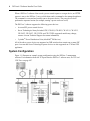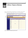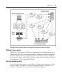
1
DSVIEW® 3
Installer/User Guide
DSView 3 Software
®
Version 3.7.1
Installer/User Guide
Avocent, the Avocent logo, The Power of Being There, DSView, DSR,
MergePoint, MergePoint Unity, AlterPath, AutoView, OutLook, OSCAR,
AVWorks, Dambrackas Video Compression and Cyclades are registered
trademarks of Avocent Corporation or its affiliates in the U.S. and other
countries. All other marks are the property of their respective owners.
© 2009 Avocent Corporation. 590-395-501P
iii
TA B LE OF C ON TE N TS
Product Overview
Features and Benefits
1
1
System Components
2
Third party products
3
Partner products
4
Supported Units
4
Target devices
7
Power devices
7
System Configuration
Installation
About Installation
8
11
11
Minimum requirements for the DSView 3 software
12
Before installing and configuring the DSView 3 software
12
Installing the DSView 3 Software
13
Upgrading the DSView 3 Software
16
Recommended upgrade process
16
Configuring the DSView 3 Software
17
Running the DSView 3 Software
19
Minimum client requirements
19
Opening a client session
20
Regaining access
22
Uninstalling the DSView 3 Software
22
Closing a DSView 3 Software Session
23
Java Installation
23
Avocent Viewer Plug-in Installation
24
Installing the DSR Remote Operations Software
24
DSView 3 Explorer Windows
Accessing Target Devices
27
28
Using the Side Navigation Bar
28
Using Windows
30
iv
DSView® 3 Software Installer/User Guide
Sorting information in a window
30
Filtering information in a window
30
Saving information in a window
32
Using the Customize link in windows
32
Displaying pages
33
Bookmarking a window
34
Printing a window
35
Refreshing a window
35
Using keyboard commands
35
Basic Operations
DSView 3 Help
37
37
Configuring the DSView 3 help location
37
Installing DSView 3 help on a local server
38
Global System Properties
38
Legal Notice
39
PCI Compliance Configuration
39
Profiles
40
Changing user options
41
Changing the color scheme
41
Changing your password
42
Choosing the serial session application
42
Specifying a user certificate
43
Specifying an SSH key
43
Enabling user credential caching
44
Built-in User Groups
45
Preemption Levels
46
Internet Explorer Considerations
48
Managing ActiveX® controls
48
Security zones
49
Advanced Internet options
51
Table of Contents
Certificates
System certificate policy and trust store
v
52
53
Integrated Windows Authentication
55
Firewalls
56
VPNs
57
NAT Devices
59
Licenses
60
Adding a new license key
63
System Information
64
ISV Partners
64
DSView 3 Servers
Server Properties
65
65
Server certificates
67
Avocent proxy server
72
Server trap destinations
73
Client session information
73
DSView 3 software modem sessions
74
Email
76
Unit status polling
76
Backing up and Restoring Hub Servers Manually
77
Spoke Servers
80
Replication
84
Authentication Services
Supported Authentication Services
87
87
DSView 3 software internal authentication service
88
Active Directory external authentication service
90
Windows NT external authentication service
97
LDAP external authentication service
99
RADIUS external authentication service
104
TACACS+ external authentication service
106
vi
DSView® 3 Software Installer/User Guide
RSA SecurID external authentication service
110
User Authentication Services Window
113
Units View Windows
Types of Units View windows
115
115
Topology view
116
Accessing Units View windows
118
Showing and hiding units
119
Units View windows fields
120
Multiple unit operations from a Units View window
124
Unit Overview Windows
125
Unit Status Window
127
Adding and Deleting Units
Adding Units
129
129
Wizards that add units
130
Adding a single managed appliance
131
Adding a single embedded appliance
133
Adding managed appliances from a range or list of IP addresses
135
Adding a generic appliance or an EVR1500 environmental monitor
137
Adding a target device
137
Deleting Units
Automatically deleting attached units
Synchronizing the DSView 3 Software Database
Name Synchronization
138
138
141
141
Automatic name push
142
Automatic name pull
143
Manual name push
145
Manual name pull
145
Topology Synchronization
146
Automatic topology synchronization
147
Topology synchronization options in the Add Unit Wizard
148
Table of Contents
vii
Topology synchronization options in the Resync Wizard
149
Merging target devices
150
Merging or splitting cascade switches
152
Automatic Discovery
152
Automatic Inheritance for Group Memberships and Properties
153
Managing Units
Appliance Configuration Templates
155
155
Saving appliance configuration templates
155
Modifying appliance configuration template properties
156
Applying appliance configuration templates
157
Unit Properties
158
About Access Rights
163
How access rights can be assigned
165
Unit Access Rights
165
Managed Appliance Settings
166
Managed Appliance Status
168
Managed Appliance SNMP Settings
169
Target Device Services
170
Target Device Settings
172
Target Device Naming
173
IQ Module Settings
174
KVM Switch and Cascade Switch Settings
175
OSCAR interface settings
177
Local Account Settings
178
Embedded Units
181
Launching embedded unit sessions
182
Changing embedded unit credentials
182
Asset and Usage Reports
184
Asset
184
Usage
185
viii
DSView® 3 Software Installer/User Guide
Power Devices and Power Device Sockets
Power Devices
187
187
Power Device Input Feed
189
Power Device Sockets
191
Power Control of Devices Attached to Power Devices
192
Unit Sessions and Connections
Managed Appliance Session Settings
Customizing the Appliance Sessions window
Active Sessions
195
195
195
201
All active sessions
201
Active sessions on a target device
203
Active modem sessions
205
Connections to Units
207
Connection display format
207
Renaming a managed appliance connection
209
Adding and deleting target device connections
209
Merging virtual and physical target device connections
210
Data Logging
Configuring Data Logging
211
212
Enabling the SSH server
213
Enabling the Syslog server
214
Enabling and disabling data logging on units
214
Verifying the data logging settings for each connection
215
Viewing and customizing the SSH server settings
216
Configuring the buffer warnings events as SNMP
217
Specifying where data log files will be stored
217
Archiving and deleting data log files
218
Viewing Data Log Files
SSH Passthrough Sessions
Configuring SSH Passthrough
220
223
223
Table of Contents
ix
Enabling SSH Passthrough
224
SSH port sharing
224
SSH Passthrough Sessions
225
Establishing an SSH Passthrough connection to a unit
226
Escape key sequence
228
Break sequences
229
Transferring read/write access
230
Disconnecting a session
231
Displaying session output
231
Supported service processor commands
231
Grouping Units
Site, Department and Location Groups
233
233
Custom Fields
236
Unit Groups
239
Unit group hierarchy
241
Adding or deleting a unit group
244
Changing the unit group properties
245
DS Zones
Managing and Accessing Zones
249
249
Enabling DS Zones
249
Creating zones
249
Accessing zones
250
Transferring units to a zone
251
Managing zone properties
252
Using Zones
254
Units actions in a zone
254
Managing User Accounts
User Accounts Windows
261
261
Adding User Accounts
263
Deleting User Accounts
266
x
DSView® 3 Software Installer/User Guide
Unlocking User Accounts
266
Resetting a User Account Password
266
Changing User Account Properties
267
Username
267
User certificates
268
User SSH key
268
User password
269
User account restrictions and expiration settings
269
User group membership
270
Preemption level
271
Address
271
Phone contact
271
Email contact
272
User notes
272
Custom field properties
272
User Access Rights
User Groups
Adding User-defined User Groups
273
275
276
Deleting User-defined User Groups
279
User Group Properties
279
Changing User Group Members
280
User Group Access Rights
281
Using the Video Viewer
About the Video Viewer
285
285
Window Features
286
Opening a KVM Session
288
Opening an exclusive KVM session
288
Connecting to an existing session
289
Video Viewer session properties
290
Session time-out
291
Table of Contents
xi
Closing a Video Viewer Session
291
KVM Session Profiles
291
General profile settings
292
Cursor profile settings
294
Toolbar profile settings
295
Video profile settings
295
Managing KVM session profiles
297
Using Menu Commands to Manage Session Settings
301
General commands
301
Cursor commands
302
Toolbar commands
303
Video commands
304
Mouse scaling command
304
Avocent Mouse Sync
305
Manual Video Adjustment
306
Saving the View
309
Displaying Video Viewer Users
309
Scan Mode
310
About scan mode
310
Thumbnail Viewer features
311
Performing Thumbnail Viewer tasks
313
Macros
Macro groups
314
317
Power Control of Devices Attached to Power Devices
320
Using Virtual Media
320
Virtual Media dialog box
321
Virtual media session settings
322
Opening a virtual media session
323
Closing a virtual media session
325
Using Smart Cards
325
xii
DSView® 3 Software Installer/User Guide
Video Viewer Troubleshooting
Using the Telnet Viewer
About the Telnet Viewer
Telnet Viewer Window Features
Telnet Viewer window toolbar
326
327
327
328
329
Security Property
330
Opening a Session
331
Customizing the Telnet Viewer
331
Customizing Session Properties
332
Login scripts
335
Reviewing Session Data
336
Macros
337
Macro groups
339
Logging
341
Copying, Pasting and Printing Session Data
344
Power Control of Devices Attached to Power Devices
345
Closing a Telnet Viewer Session
346
Using Tools
Using Unit Tools
347
347
Exporting units
347
Exporting access rights
349
Merging target devices
350
Merging target device endpoints
351
Importing DSView 2.x software databases
351
Importing data
355
Using the Managed Appliance Tools
356
Rebooting
357
Upgrading firmware
358
Resynchronizing units
358
Saving a managed appliance configuration
360
Table of Contents
xiii
Restoring a managed appliance configuration
360
Saving a managed appliance user database
361
Restoring a managed appliance user database
361
Using Tasks
Using the Tasks Window
363
363
Adding tasks
364
Specifying when to run tasks
364
Adding Tasks Using the Add Task Wizard
367
Task: Backup DSView 3 software database and system files
367
Task: Configure SNMP trap settings on a managed appliance
368
Task: Power control a target device
369
Task: Exporting an event log .csv file
370
Task: Exporting an Asset Report to a .csv file
371
Task: Exporting a Usage Report to a .csv file
372
Task: Migrating units
373
Task: Sending an IPMI chassis control command to target devices
375
Task: Test modem connections to selected units
376
Task: Updating the firmware of an appliance type
377
Task: Validating user accounts on an external authentication server
378
Task: Pull names from selected units
378
Task: Update topology for selected units
379
Task: Backup Power Manager database
380
Task: Restore Power Manager database
381
Running tasks manually
382
Displaying task results
382
Deleting tasks
383
Changing tasks
383
Firmware Management
Events and Event Logs
Event Severity and Categories
384
387
387
xiv
DSView® 3 Software Installer/User Guide
Event severity
387
Event categories
388
Email Notifications
389
Enabling and Disabling Event Logging
391
Displaying the Event Log
392
Event states
394
Using the date filter
395
Changing the Event Log Retention Period
395
Creating an Event Log .csv File
396
Plug-ins
Recommended Sequence for Adding/Upgrading Plug-ins
399
399
Adding Plug-ins
400
Displaying Plug-in Information
401
Managing Plug-ins
403
Upgrading a plug-in
403
Disabling and activating a plug-in
403
Appendix A: Technical Support
405
Appendix B: TCP and UDP Ports
407
Appendix C: DSR Remote Operations Software
415
Appendix D: Terminal Emulation
425
Appendix E: Regaining Access to the DSView 3 Software
443
Appendix F: Glossary
445
1
1
Product Overview
The DSView® 3 management software version 3.7 is a secure, web browser-based, centralized
enterprise management solution that allows users to remotely access, manage, monitor and control
target devices through Avocent managed appliances. A session may be launched to a target
device with a single point of access.
Features and Benefits
Network rebooting and troubleshooting
The DSView 3 software uses industry standard IP connections so that you can easily troubleshoot
a server, or even reboot it, from the Network Operations Center (NOC), from your desk or from
any location in the world. With the DSView 3 software, you can access all of your data center
devices from a single screen - making complex network access and control remarkably easy.
Using out-of-band management, the software can be used to reach and restart servers or other
devices that are not functioning or responding to in-band commands, regardless of the state of the
equipment’s operating system.
Web-based access and control
The DSView 3 management software provides secure “point-and-click” browser-based access to
control virtually any data center device using managed appliances from DSView 3 software
clients located anywhere in the world.
Secure authentication and communication
Secure Socket Layer (SSL) encryption may be used to encrypt data traveling within the DSView
3 software system. Users may be authenticated through internal or external services such as
LDAP, Active Directory, NT Domain, TACACS+, RADIUS and RSA SecurID.
Unit and user management
The DSView 3 management software provides centralized network access, control and security
for managed appliances. A DSView 3 software administrator may add, remove, delete and change
2
DSView® 3 Software Installer/User Guide
settings for managed appliances and target devices, including assigning permissions and perdevice contact information, which are stored on the DSView 3 server. A DSView 3 software
administrator may also assign unique permissions which allow individual users or a group of
users access to units or groups of units.
Proxy server access
The proxy server feature allows keyboard, video and mouse (KVM) and serial sessions to be
proxied through the DSView 3 server. When a session is initiated with a target device, the
viewer communicates using the Avocent Proxy Protocol (APP) and the DSView 3 server makes
a direct connection to the appliance.
Virtual media
On supported KVM switches, a virtual media capable IQ module and the virtual media feature
allow the client workstation user to load files onto USB2-compatible target devices when the
usual network resources are unavailable.
Mapping physical drives or image files on the client system as virtual drives on the target
device can accommodate critical tasks required on the target device, such as operating system
installation or recovery, BIOS updating and configuration backups.
Dual stack support for IPv4 and IPv6
The DSView 3 server is a dual stack host for IPv4 and IPv6 network protocols. Several Avocent
appliances support IPv6, including DSR® switches, ACS advanced console servers, and
MergePoint® service processor (SP) managers.
Virtual segregation of resources with DS Zones
DS Zones provide virtual segregation of data center resources, including appliances, target
devices and virtual machines. You can manage the users, licenses and authentication services
assigned to each zone, and transfer units among zones.
System Components
The DSView 3 software system contains the following components.
DSView 3 management software
The DSView 3 software resides on the DSView 3 server (host or hub computer) and provides a
web gateway and services for managing units (appliances and target devices) using a web
browser. The gateway allows for IP-based video, serial management, Telnet Viewer, third party
Telnet viewer, web browser and other supported session types.
Chapter 1: Product Overview
3
Users may connect to the DSView 3 server from DSView 3 software clients and use the
DSView 3 Explorer windows to communicate with the system.
DSView 3 server
The DSView 3 server contains the DSView 3 management software. The server provides a
centralized database for storing configuration, user, unit and system information. It also
provides services for authentication, access control, logging events, monitoring and license
management.
You may configure one or more spoke (backup) servers in addition to the hub server. The hub
server is responsible for maintaining the master copy of the database in a DSView 3 software
system. Only one server in a DSView 3 software system may be configured as the hub server.
Spoke servers perform database replication with the hub server. The hub server acts as the
coordinator for database replication between itself and all of the other spoke servers in a
DSView 3 software system. A hub server and a spoke server both offer the same DSView 3
software functionality to a user. The distinction of hub or spoke refers only to the database
replication role that the server plays and not with the functionality that the server provides.
Adding one or more spoke servers to a DSView 3 software system provides redundancy and the
ability to distribute DSView 3 software functionality across multiple sites.
After the hub server and optional spoke server(s) are configured, you may create and configure
the type of access levels for users within your network environment. You may also set up event
logs to record full details of user access and other events.
DSView 3 software client
A DSView 3 software client is a computer with a web browser that can access the DSView 3
management software installed on the DSView 3 server.
Third party products
Third party products are not a part of the DSView 3 software, but are supported for use with it.
External authentication servers - An external authentication server enables the DSView 3
server to broker authentication requests from users requesting access to the DSView 3 software
system.
SNMP managers - The SNMP (Simple Network Management Protocol) manager monitors the
managed appliances and receives SNMP traps from the DSView 3 software on the server. An
example of an SNMP manager is the HP OpenView product.
Third party Telnet viewers - A third party Telnet viewer may be used for serial sessions instead
of the DSView 3 software Telnet Viewer.
4
DSView® 3 Software Installer/User Guide
Third party session software - Third party software such as RDP or VNC, when properly
installed and configured on the target device, may be enabled for use within the DSView 3
software for initiating sessions with the target device. At the beginning of a session, the RDP
viewer allows users to map local resources for use with virtual media.
NOTE: RDP is only available on supported Windows system clients.
Partner products
Environmental monitoring with Uptime Devices
DSView 3 software can help you access Uptime Devices SensorHub environmental monitoring
equipment so you can quickly detect environmental conditions (equipment to track
temperature, humidity, airflow, water, voltage and contact closures) that could adversely affect
operation of servers and other network devices. Visit www.uptimedevices.com for ordering
information.
Proactive Network Security with NetClarity Auditor Enterprise
Integrate NetClarity Auditor Enterprise with the DSView 3 software and manage one or more
Auditor appliances to alert, block and correct critical IT security and compliance problems in
your data center and entire enterprise network. Visit www.netclarity.net for ordering
information.
Avocent DSView 3 Connector for HP® Software
The DSView 3 Connector for HP Software extends the capabilities of HP Software Network
Node Manager (NNM) and Operations for Windows (OVOW). Seamless access and control
allows critical management functions for dispersed IT environments. Out of band connectivity
offers solutions for lights out data centers and ensures quick and efficient troubleshooting and
repair from the HP console.
Supported Units
For management functions, the DSView 3 software client uses HTTPS (Hypertext Transfer
Protocol with SSL encryption) to send a request to the DSView 3 server, which then sends a
command to the managed appliance. The appliance then performs the requested function.
The DSView 3 software supports the managed appliances listed in this section. Other
appliances may be supported by plug-ins; see the Avocent web site, www.avocent.com, for a
list of plug-ins that may currently ship with the DSView 3 software and/or that can be added to
the DSView 3 software. See Plug-ins on page 399 for information about adding and managing
plug-ins in the DSView 3 software system.
Chapter 1: Product Overview
5
Cyclades® ACS advanced console server
ACS advanced console servers allow users to access serially attached devices over a standard
TCP/IP connection using the Avocent Telnet Viewer, a third party Telnet viewer or a Secure
Shell (SSH) client. These serial sessions can be shared among multiple users across multiple
DSView 3 servers. For more information, see the ACS console server plug-in documentation.
LANDesk® Server Manager
The DSView 3 management software plug-in for LANDesk Server Manager allows you to
access the LANDesk Server Manager and its target devices from within the DSView 3 software.
This integrated system provides complete life cycle and systems management for multiplatform
server infrastructures. Use the browser-based software to manage server performance and
availability, and launch sessions to target devices from a single point of access.
LANDesk Server Manager supports rack-mounted and blade servers with low-impact services
that let users choose the level of management coverage – from device discovery to extended
performance analysis, security and configuration control. It enables enterprises to take
inventory, provision, patch, monitor and instantly assess server health and ensure optimum
availability.
DSR® switches
DSR switches allow KVM signals to be transmitted over a standard TCP/IP network
connection. Some DSR switches may be connected using a modem, which provides benefits for
branch offices such as low cost and dial-up performance.
The DSView 3 software supports the following DSR switch models:
800, 1010, 1020*, 1021*, 1022*, 1024*, 1030*, 1031*, 1161, 2010, 2020*, 2030*,
2035*, 2161, 4010, 4020*, 4030*, 4160, 8020*, 8030*, 8035*
*These models contain a dedicated serial port for connecting an external modem for
use with the DSR Remote Operations software.
For DSR switches, a target device is first attached to an IQ module, which is then attached to a
DSR switch. DSView 3 software clients communicate with target device ports using a Video
Viewer connection between the client and the managed appliance.
The DSR switches allow the cascading of legacy analog KVM switches from DSR switch ports,
which may be managed in a DSView 3 software system. Certain DSR switch models also allow
the cascading of another switch. For more information, see the DSR Switch Installer/User
Guide.
NOTE: PEM cascade devices are not supported.
6
DSView® 3 Software Installer/User Guide
MergePoint® service processor (SP) manager
The MergePoint service processor manager is a secure, centralized enterprise management
solution for target devices equipped with IPMI, HP iLO and Dell DRAC service processors.
You can use the DSView 3 software to access, monitor and control the MergePoint SP manager
and attached target devices.
The MergePoint SP manager provides a standardized interface independent of the management
protocols used to manage each target device. Management operations can be performed either
by using commands or scripts over a Telnet or SSH version 2 session or by using the
appliance’s web interface from a standard web browser.
For more information, see the MergePoint appliance plug-in documentation.
Cyclades OnSite branch office appliance
OnSite branch office appliances may be used to access multiple traditional or headless servers,
networking devices, infrastructure components or any other device with a serial console or
KVM port. You can use the DSView 3 software to access, monitor and control the OnSite
appliance and attached target devices. For more information, see the OnSite appliance plug-in
documentation.
Virtual environments
The DSView 3 management software plug-in for Virtualization allows you to access and
control virtual machines from the DSView 3 software. Supported unit types include VMware®
VirtualCenters, ESX Servers and virtual machines, as well as Citrix® XenServersTM and virtual
machines. You can launch a Virtual Network Computing (VNC), Remote Desktop (RDP),
Secure Shell 2 (SSH) or VMware viewer session to supported virtual machines from a single
point of access. For more information, see the Virtualization plug-in documentation. Licenses
may be required; see your Avocent representative or www.avocent.com for more information.
Blade chassis
The DSView 3 software plug-in for Blade Chassis allows you to access multi-vendor blade
chassis and blades from the DSView 3 software. You can launch a KVM session to any
managed blade from a single point of access. For a list of supported blade chassis and other
information, see the Blade Chassis plug-in documentation.
Generic appliances
Generic appliances manage data center devices such as routers. These devices may be managed
within a DSView 3 software system by launching a standard web browser to the device URL or
by opening a Telnet session.
Chapter 1: Product Overview
7
Embedded units
Using the DSView 3 software, you may add/delete, configure/display properties, and launch
video sessions to the following versions of third party embedded units:
•
IBM® ASM (Advanced System Management) RSA II (Remote Supervisor Adapter II) Version 5, Build GRE132AUS
•
DRAC 4 (Dell™ Remote Access Controller) - Version 1.0, Build 06.14
•
HP iLO (Integrated Lights-Out) - Version 1.20
•
NEC IPF (Itanium Processor Family) - Version 0.5.1.20
For management functions (other than launching video sessions) that are not performed by the
DSView 3 software, see the documentation for the unit.
Legacy units
The following legacy units are supported in the DSView 3 software.
•
DSI5100 IPMI proxy appliances
•
EVR1500 environmental monitors
•
DS1800 digital switches
•
AutoView® 200-4, 200-8, 400-4, 400-8, 416, 424 and 2000-AM switches (these switches
must be Flash upgraded to be added to a DSView 3 software system)
•
OutLook® 140ES, 180ES, 280ES, 1160ES, 2160ES and 4160ES switches
•
Cyclades KVM/net KVM over IP switches
•
Cyclades KVM/net Plus KVM over IP switches
•
Cyclades TS appliances
•
CCM console management appliances
•
CPS810 and 1610 serial over IP network appliances
Target devices
Target devices encompass a wide range of data center components such as servers and routers
that a DSView 3 software administrator may manage virtually through the DSView 3 software
system. A target device is added automatically to your DSView 3 software system when the
supported managed appliance is added. A target device may also be added individually.
Power devices
A power device is a type of target device that can be cascaded from a managed appliance.
8
DSView® 3 Software Installer/User Guide
When a DSView 3 software client sends a power control request to a target device, an HTTPS
request is sent to the DSView 3 server, which then sends a command to the managed appliance.
The command is converted and serially sent to the power device. The power device then
performs the requested action (for example, turning a power outlet on or off).
The DSView 3 software supports the following power devices:
•
Avocent SPC power control devices
•
Server Technologies Sentry Switched CDU CW-8H1, CW-8H2, CW-16V1, CW-16V2,
CW-24V2, CW-24V3, CW-32VD1 and CW-32VD2 (supported models may change;
contact Avocent Technical Support for current information)
•
Cyclades® Power Distribution Units (AlterPath® PM devices)
All of the above power devices are supported on DSR switches that contain one or more SPC
ports. Avocent and Server Technologies power devices are also supported on CCM and CPS
appliances.
System Configuration
Figure 1.1 illustrates an example system configuration using the DSView 3 management
software. For information about the TCP ports that the DSView 3 software uses, see TCP and
UDP Ports on page 407.
Chapter 1: Product Overview
Figure 1.1: Example System Configuration
Table 1.1: DSView 3 Software System Configuration Descriptions
Number
Description Number
Description 1
DSView 3 Software Client
12
Power Device
2
Hub DSView 3 Software Server
13
Generic Appliance
3
Spoke DSView 3 Servers (Optional)
14
Hypervisor Manager
4
External Authentication Servers (Optional)
15
Target Device
5
SNMP Manager (Optional)
16
IQ Module
6
TCP/IP
17
Cascade Switch
7
Replication
18
Target Devices
8
ACS Advanced Console Server
19
MergePoint SP Manager
9
Power Device
20
Hypervisor Server
10
DSR Switch
21
Virtual Machines
11
OSCAR® Interface
22
Blade Chassis
9
10
DSView® 3 Software Installer/User Guide
11
2
Installation
This chapter describes the following installation sequence for the DSView 3 software:
•
What you should do before installing the DSView 3 software
•
Installing the DSView 3 software
•
Configuring the DSView 3 software, plus considerations when upgrading
•
Running the DSView 3 software, that is, start a client session
Final sections describe how to change your password, uninstall the software, end a DSView 3
software session and install Java.
About Installation
When the DSView 3 management software is installed, the DSView 3 software database and a
hub server are also installed on the dedicated server.
The DSView 3 software may be installed on a computer containing an existing DSView 2.x
software authentication server without causing any interference with the operation of the
DSView 2.x software system. The DSView 2.x software authentication server and the DSView 3
software may run on the same dedicated server at the same time.
Rebooting the dedicated server is not required prior to using the DSView 3 software.
Once the DSView 3 software is installed and you have configured the hub server, users may log
in at another computer as a DSView 3 software client, using a supported web browser.
You may also install the DSView 3 software on additional computers and configure them as
spoke servers. See Spoke Servers on page 80 and Installing the DSR Remote Operations Software
on page 24.
NOTE: A license key permits the operation of the DSView 3 software on the dedicated server. The license key also
specifies the number of clients that may use the software and the number of spoke servers allowed on a system. See
Licenses on page 60.
12
DSView® 3 Software Installer/User Guide
Minimum requirements for the DSView 3 software
The following are the minimum requirements for installing the DSView 3 software on a
dedicated hub server or a computer that will function as a DSView 3 software spoke server:
•
For supported Windows and Linux systems: 2 GHz Pentium or equivalent processor
•
For supported Solaris systems: 1 GHz UltraSparc III processor
•
4 GB of RAM - additional memory may be needed, depending on the number of plug-ins
installed and appliances supported
•
100BaseT NIC (1GByte LAN recommended)
•
10 GB of free disk space - additional disk space may be required for data logging and
plug-ins
•
One of the following operating systems:
•
Windows Server® 2003 Standard, Enterprise and Web Edition
•
Windows Server 2008 Standard, Enterprise and Datacenter Edition
•
Windows Web Server 2008
•
Red Hat® Enterprise Linux, Version 4 (AS, ES and WS products)
•
Red Hat Enterprise Linux, Version 5
•
Sun® Solaris™ SPARC 9 and 10
•
Novell® SUSE® Linux (x86) Enterprise Server 9 or 10
NOTE: The DSView 3 software is also supported on any of these operating systems running as a guest OS in a
virtual environment. However, while the DSView 3 software is expected to function properly on a guest OS in the
virtual environment, there may be unknown performance implications.
Before installing and configuring the DSView 3 software
Before installing the DSView 3 management software, install the managed appliance hardware.
If the computer will be a hub server, you will need the license key obtained from Avocent and
provide a username and password to use for initial log in.
If the computer will be a spoke server, you will need to identify the associated hub server and
provide the name/password of the hub server’s DSView 3 software administrator.
To prevent potential mouse conflicts, you may configure certain settings on each server
connected to a KVM switch or serial console appliance. For details, see the Mouse and Pointer
Chapter 2: Installation
13
Settings Technical Brief, which is available on the DSView 3 software DVD and on the
Avocent web site.
Installing the DSView 3 Software
The DSView 3 management software may be installed using the DSView 3 software DVD or
by downloading the software in a self-extracting .zip file from the Avocent web site.
NOTE: If you are upgrading the DSView 3 software from a previous version, it is strongly recommended that you
perform a database synchronization between the hub and spoke servers; see Replication on page 84. You should
also back up the hub server prior to upgrading the DSView 3 software; see Backing up and Restoring Hub Servers
Manually on page 77. Failure to perform synchronization and backup may have detrimental effects. A backup
should be performed both before the upgrade and immediately following the upgrade.
To install the DSView 3 software on a supported Windows system:
1.
Log on to the dedicated server as Administrator.
2.
To install from a DVD:
a.
Insert the DSView 3 software DVD. An autorun file opens a menu of installation
options.
b.
Click Install DSView 3 Software.
-orIf autorun is not enabled, type <drive:>\DSView\win32\setup.exe, where
<drive:> is the letter of your DVD drive.
A dialog box will indicate that the server will be verified to ensure it meets
the minimum requirements for installing the DSView 3 software.
To install from a downloaded file:
3.
a.
Using your web browser, download the DSView 3 software from the Avocent web
site. Go to www.avocent.com and click the Support link. On the Technical Support
page, click the Product Upgrades link, then select DS Software Upgrades.
b.
Double-click on the downloaded installation package (setup.exe). A dialog box will
indicate that the server will be verified to ensure it meets the minimum requirements
for installing the DSView 3 management software.
If the current or an earlier version of the DSView 3 software is already installed, the
Installed Product Found: Same Version message box will appear. Click OK to reinstall the
DSView 3 software or Cancel to exit setup.
14
DSView® 3 Software Installer/User Guide
4.
The Check for an UPDATED version window will open. (If the DSView 3 software is
already installed on the dedicated server, a message box will display. Click OK to close the
box.)
a.
Click Next to reinstall the software, or click Cancel to stop the reinstallation.
b.
Click Check for UPDATES and then click Next to check the Avocent web site for the
most recent DSView 3 software installation package. Go to step 5.
-orClick Next to install the DVD or downloaded version of the DSView 3
software. Go to step 6.
5.
If a newer version of the DSView 3 software is found, an Update Available message
appears.
a.
Click OK to download the latest DSView 3 software installation package. The
installation will be cancelled and the server’s default web browser will launch and
open in the Product Upgrades and Options page of the Avocent web site.
-orClick Cancel to resume installation of the older version of the DSView 3
software. Go to step 6.
b.
Type your email address and password, and then click Submit to log in to the web site.
c.
Download the DSView 3 software installation package, log out and close the web
browser. Return to step 2.
6.
The Introduction window will open. Click Next.
7.
The License Agreement window will open.
•
If you accept the terms, click I accept the terms of the License Agreement and then
click Next. Go to step 8.
•
If you do not accept the terms, click I do NOT accept the terms of the License
Agreement. A License Agreement Warning message box will appear.
•
If you click Quit, the installation will exit without installing the DSView 3 software.
•
If you click Resume, you will be returned to the License Agreement window.
The DSView 3 software license agreement may also be viewed from the User Login
window by clicking the Avocent DSView 3 End User License Agreement link. The
agreement will appear in a separate web browser window.
Chapter 2: Installation
15
8.
If the default TCP port used by the dedicated server hosting the DSView 3 software (TCP
port 443) is not available, the Define Web Application Server TCP port window will open.
Type the port you want to use in the TCP port # field, then click Next. (Clicking Cancel
exits the Checking for an Updated version installation program.)
9.
If the default TCP port used by the Avocent proxy server (TCP port 1078) is not available,
the Define TD (target device) Session Viewer Proxy TCP port window will open. Type the
port you want to use in the TCP port # field, then click Next.
10. If the default ports used by the SSH server and the Syslog server for data logging are not
available, appropriate windows will open. Type the port you want to use, then click Next.
11. The Choose Destination Location window will open.
a.
Click Choose and use the Browse for Folder dialog box to select a directory in which
to install the DSView 3 software.
-orClick Restore Default Folder to restore the installation directory to the default
(C:\Program Files\Avocent DSView 3).
b.
Click Install.
The Installing... window will open and display the progress of the installation. The
software will be installed in the specified folder, a Start - Programs - DSView 3
shortcut menu will be generated and the DSView 3 software service startup will be
verified.
If a previous version of the DSView 3 software already exists on the dedicated server,
message boxes may appear, prompting you to confirm overwriting existing files. Click
Yes to All.
12. When the software has finished installing, the Successful Service Startup message box will
appear. Click Continue.
13. The Installation Complete window will open.
•
To begin configuration of the DSView 3 software, click Done; see Configuring the
DSView 3 Software on page 17. A Security Alert dialog box will appear containing
certificate information and a warning that the generator of the certificate is not trusted.
This occurs because the DSView 3 server certificate created when the server is
installed is a self-signed certificate. You may either import the certificate into the
DSView 3 software client web browser (choosing to trust the certificate) or obtain a
server certificate from a Certificate Authority (CA) trusted by the web browser.
16
DSView® 3 Software Installer/User Guide
•
To configure the DSView 3 software at a later time, click X (Cancel) in the top right
corner of the window.
To install the DSView 3 software on a supported Linux or Solaris system:
1.
Log in to the server as root.
2.
Insert the DSView 3 software DVD into your DVD drive. If AutoMount is supported and
enabled, open a command window and continue with step 3.
If your system does not support AutoMount, issue the following command to mount
the DVD volume: mount <device> <mount point>, where <device> and <mount
point> are the names of your server’s DVD Linux or Solaris device and mount point
directory, respectively.
For example, to mount the first IDE cdrom on /media/cdrom, enter the command:
mount /dev/cdrom /media/cdrom
3.
Enter the following command to access the readme file:
less /<mount point>/DSView/readme
For example, the following command accesses the readme file on the /media/cdrom
mount point.
less /media/cdrom/DSView/readme
4.
Follow the instructions in the readme file.
Upgrading the DSView 3 Software
When upgrading to a newer version of the DSView 3 software, all DSView 3 servers should be
upgraded at the same time. The DSView 3 hub server should be upgraded first, followed by
each spoke server.
Before upgrading, a replication should be performed (see Replication on page 84), then a
backup immediately before and after upgrading the DSView 3 software (see Backing up and
Restoring Hub Servers Manually on page 77).
The firmware for the appliances may also need to be upgraded in order to support new
functionality in the DSView 3 software. The DSView 3 software should work with the existing
firmware revisions, but in cases where new functionality is not supported until the firmware is
upgraded, the DSView 3 software will indicate this in the GUI.
Recommended upgrade process
NOTE: In order to safely upgrade the DSView 3 software, and to provide for a roll-back path in case of upgrade
failures, perform each of the following steps. If your DSView 3 configuration does not include spoke servers, skip
steps that refer to spokes.
Chapter 2: Installation
17
To upgrade the DSView 3 software:
1.
Ensure that you are able to upgrade the hub server and any spoke servers during the same
upgrade time. The expected time to perform this procedure is 30 minutes. However, due to
differences in DSView 3 configurations and amounts of data, your time may vary.
2.
Verify that the installer files for both the new and old versions (in case recovery is needed)
are available to you.
3.
Perform a replication of all spoke servers. See Replication on page 84.
4.
Backup all hub and spoke servers. See Backing up and Restoring Hub Servers Manually on
page 77. It is advised that all DSView 3 backup files be stored on an external device or
network drive.
5.
Verify basic functionality by navigating to a few DSView 3 windows and launching
sessions to a few target devices.
6.
Run the DSView 3 installer for the new version on the hub server.
7.
Run the DSView 3 installer on all spoke servers.
NOTE: The hub server must be upgraded prior to the upgrading the spoke servers.
8.
Verify basic functionality again by navigating to a few DSView 3 windows and launching
sessions to a few target devices.
9.
Perform another backup of the hub and spoke servers to have a baseline database of the
upgraded environment. See Backing up and Restoring Hub Servers Manually on page 77.
10. Run replication to validate that there are no errors. Errors will either be displayed in the
status panel for the replication task or in the Events Log. See Replication on page 84.
11. The firmware for the appliances may also need to be upgraded in order to support new
functionality in the DSView 3 software. See Upgrading firmware on page 358.
12. Verify basic functionality one last time by navigating to a few DSView 3 window and
launching sessions to a few target devices.
Configuring the DSView 3 Software
After the DSView 3 software has been installed, it must be configured using a web browser.
During configuration, you specify whether the computer will be a hub server or a spoke server.
If this is your first DSView 3 server installation, hub should be selected in the Select DSView
Server Role window. The hub server should be installed before any spoke servers are added.
18
DSView® 3 Software Installer/User Guide
What you will need
If the computer will be a hub server, you will need the license key obtained from Avocent and
provide a username and password to use for initial log in.
If the computer will be a spoke server, you will need to identify the associated hub server and
provide the name/password of the hub server’s DSView 3 software administrator.
To configure the DSView 3 software:
1.
If you are configuring the DSView 3 software during the installation process, you have
already clicked Done in the Launch Default Browser window.
If you quit after installing the DSView 3 software installation process (by closing the
window), select Start - Programs - Avocent DSView 3 - DSView Software.
2.
A security alert box will appear containing certificate information. See Certificates on page
52.
3.
The Select DSView Server Role window opens.
4.
•
Click Hub to assign the dedicated server as the hub server, then click Next. Go to step
3.
•
Click Spoke to assign the dedicated server as a spoke server, then click Next. Go to
step 8.
The Type in Master License Key window opens. Type the Avocent-provided license key
for the DSView 3 software hub server, then click Next. (DSView 3 software license keys
prior to version 3.0 are not valid.)
If you did not receive a license key, click the http://www.avocent.com/activation link
to obtain a license key.
If the entered license is already in use on another server, a license violation will occur
when you log in, and you must configure the server as a spoke server.
5.
The Type in Initial Administrator Account window opens. Type a username, a password
and confirm the password of the user to whom you wish to give administrator privileges.
Usernames are case sensitive and may contain up to 64 characters. Click Next.
6.
A Request in Progress message will appear. The license key will be installed and a
DSView 3 software administrator account will be created. The built-in user groups will
also be created.
7.
The Completed Successful window will open when configuration is completed. Click
Finish.
8.
The User Login window will open in the DSView 3 Explorer.
Chapter 2: Installation
19
You may now log in using the username and password specified during configuration.
If you chose to configure the server as a spoke server in the Select DSView Server Role
window or if you entered a duplicate software license key in the Type in Master License Key
window, continue with the following steps.
NOTE: The DSView 3 software versions of the spoke server and the hub server must match in order to register the
spoke server. For example, you may not register a spoke server running DSView 3 software version 3.0 with a hub
server running DSView 3 software version 3.2.
9.
The Type in Hub Server Address and Port window will open. Type the address of the
DSView 3 software hub server using standard dot notation (xxx.xxx.xxx.xxx) or type the
DNS name in the Address field. Click Next.
10. The Accept DSView Server Certificate window will open. Click Next to accept the
certificate.
11. The Type in Hub Administrator Credentials window will open. Type a valid username and
password for a user with DSView 3 software administrator privileges on the DSView 3
software hub server. Click Next.
12. The Registering Spoke Server window will open with the message Request In Progress
Please Wait The configuration of the spoke server will be saved to the database of the hub
server and the spoke server’s certificates will be installed on the hub server.
13. The Completed Successful window will open when the spoke server has been added. Click
Finish.
Running the DSView 3 Software
DSView 3 software clients access the DSView 3 management software host using a supported
web browser. Any software required by the client, such as applets and the Java Runtime
Environment (JRE), will be automatically installed by the DSView 3 server host.
The DSView 3 software uses Secure Sockets Layers (SSL) encryption to send data between the
DSView 3 software host and the web browser on the client to ensure data integrity and privacy.
When a user attempts to log in to a DSView 3 software client session, the authentication
service configured in the DSView 3 software by the DSView 3 software administrator verifies
the credentials of the user. Security alerts related to the certificates on the DSView 3 software
host may appear. See Certificates on page 52.
Minimum client requirements
The following are the minimum requirements for a DSView 3 software client:
•
1 GHz Pentium or equivalent processor
20
DSView® 3 Software Installer/User Guide
•
512 MB of RAM
•
10 or 100BaseT NIC (100 recommended)
•
XGA video with graphics accelerator
•
Desktop size setting of at least 800 x 600
•
Color palette of at least 256 colors
•
One of the following operating systems:
•
Windows XP Home Edition or Professional
•
Windows 2003 Server Standard, Enterprise or Web Edition
•
Windows Vista Ultimate or Business
•
Red Hat Enterprise Linux, Version 4 (AS, ES and WS products)
•
Red Hat Enterprise Linux, Version 5
•
Sun Solaris SPARC 9 and 10
•
Novell®SUSE Linux (x86) Enterprise Server 9 or 10
•
Macintosh OS X version 10.4 and later (32-bit OS only)
•
Adobe®Flash Player version 9.0 or later
•
One of the following browsers:
•
Microsoft®Internet Explorer 6 or 7
•
Firefox® 2 or 3
Install the latest updates and service packs available for your browser.
If you are using Firefox, the Video Viewer and the Telnet Viewer clients require Java;
see Java Installation on page 23.
Opening a client session
Before opening a client session
•
Enable cookies and JavaScript on the client’s web browser.
•
Configure the web browser. If you are using Internet Explorer, see Internet Explorer
Considerations on page 48.
To open a client session:
NOTE: If DSView 3 Software Client Certificate Authentication or DSView 3 Software Client Integrated Windows
Authentication is being used, the user will not be required to log in. See Certificates on page 52.
Chapter 2: Installation
1.
21
From the DSView 3 software client web browser, enter the URL of the server host in the
address bar in the format:
https://<servername>/dsview
In this case, <servername> is the DNS name of the host system, or the IP address in
standard dot notation (xxx.xxx.xxx.xxx).
NOTE: To avoid multiple security warnings, enter the DNS name.
-orIf you are opening the session on the DSView 3 server, you may select Start Programs - Avocent DSView 3 - DSView Software.
2.
Accept all security alerts that may appear as the client computer connects to the DSView 3
server. The DSView 3 Explorer User Login window will open.
If an RSA SecurID external authentication service has been added to the DSView 3
software, see RSA SecurID login on page 21 below for the login procedure.
3.
Type a valid username and password in the fields provided.
Depending on the settings specified by the administrator, you may be required to
change your password before being allowed to complete the login process. See Adding
User Accounts on page 263.
4.
Click Login. The window that appears depends on the rights assigned to the DSView 3
user that is logging in.
If the client machine uses an onboard video controller and experiences video problems, be sure
the BIOS is updated to the latest version.
RSA SecurID login
When an RSA SecurID external authentication service has been added to the DSView 3
software, the login credentials include a username and a passcode. The passcode includes a PIN
and an RSA SecurID tokencode. The login request is sent to the RSA Authentication Manager.
Depending on the user configuration and state on the RSA Authentication Manager, the user
may be prompted for a second successive tokencode.
The user configuration also specifies how the 4-6 digit PIN will be generated:
•
User defined - the user must enter a PIN
•
System generated - the user cannot enter a PIN; it must be generated by the RSA server
•
User selectable - the user may choose to enter a PIN or allow the RSA server to generate it
22
DSView® 3 Software Installer/User Guide
If a PIN has not yet been assigned to the user or if security policy requires a PIN change, the
user will be prompted accordingly. If the RSA server generates the PIN, the user will be given a
brief interval to memorize it.
Regaining access
If access to a DSView 3 software system is lost, see Regaining Access to the DSView 3
Software on page 443.
Uninstalling the DSView 3 Software
To uninstall the DSView 3 software on a supported Windows system:
1.
Select Start - Settings - Control Panel. The Control Panel will appear.
2.
From the Control Panel, click Add/Remove Programs. The Add/Remove Programs dialog
box will appear.
3.
Select Avocent DSView 3 and then click Change/Remove. The Uninstall Avocent DSView
window will open.
4.
Click Uninstall.
To uninstall the DSView 3 software on a supported Linux or Solaris system:
1.
Log in to the server as root.
2.
Insert the DSView 3 software DVD into your DVD drive. If AutoMount is supported and
enabled, open a command window and continue with step 3.
-orIf your system does not support AutoMount, issue the following command to mount
the DVD volume: mount <device> <mount point>, where <device> and <mount
point> are the names of your server’s DVD Linux or Solaris device and mount point
directory, respectively.
For example, to mount a DVD which is the second IDE unit on /media/cdrom, enter the
command:
mount /dev/cdrom /media/cdrom
3.
Enter the following command to access the readme file.
less /media/cdrom/DSView/readme
Follow the instructions in the readme file.
Chapter 2: Installation
23
Closing a DSView 3 Software Session
Files are copied to DSView 3 software clients when you log in to the DSView 3 software.
When using Internet Explorer, temporary files may be removed by selecting the Delete
Temporary Internet Files command and active web components may be uninstalled by
selecting the Remove Objects command. See the Internet Explorer documentation for more
information.
To close a DSView 3 software session:
From the DSView 3 Explorer, click LOGOUT or the logout icon.
Java Installation
On non-Windows clients, the Video Viewer, Telnet and VNC Viewers require Java version 1.5.
The Telnet/SSH applet may work with other versions; the Video Viewer requires that version.
On Windows clients, Java is required to run the Avocent Telnet/SSH Viewer. If the Win32
PuTTY Telnet/SSH Viewer is selected in the user’s profile, then Java is not required on the
client. On a Windows client, it is recommended that the JRE (Java Runtime Environment) be
installed in the C:\Program Files\ location. If your system automatically installs programs in
another location, you may not be able to launch the Video Viewer. In this case, you can
configure Java to find the JRE.
To configure Java to find the JRE:
1.
Access the Java Control Panel.
2.
Select the Java tab.
3.
In the Java Application Runtime Settings panel, click View.
4.
Change the path to the installed JRE.
5.
Click OK.
For Windows, Linux and Solaris operating systems, the DSView 3 software client automatically
downloads and installs the JRE the first time it is needed. For Macintosh operating systems,
you must update Java and install the JRE using the Macintosh software updates. Refer to the
Macintosh operating system documentation for more information.
To install the JRE on a Windows client:
1.
In a DSView 3 software Units View window (see Accessing Units View windows on page
118), click an Action link.
24
DSView® 3 Software Installer/User Guide
2.
A window will open, containing a link for downloading the JRE installer. Download the
JRE installer, then close all browser windows.
3.
Click on the JRE icon to launch the installer.
4.
Restart the browser, and click an Action link.
To install the JRE on a Linux or Solaris client:
NOTE: Only one version of the JRE can be installed in the browser for DSView 3 software support. Depending on
your system’s configuration, you may have to log in as the root user to install the JRE. Contact your system
administrator if you need help with installing software as the root user.
1.
In a DSView 3 software Units View window (see Accessing Units View windows on page
118), click an Action link.
2.
A window will open, containing a link for downloading the JRE installer. Download the
JRE installer, then close all browser windows.
3.
Run the installer.
4.
Restart the browser, and click an Action link.
Avocent Viewer Plug-in Installation
On Windows clients, the Video Viewer, Telnet and VNC Viewers require the Avocent Viewer
Plug-in. If you are using Firefox 2 or Internet Explorer, the plug-in downloads automatically
from the browser window. If you are using Firefox 3, additional set up is required.
To install the Avocent Viewer Plug-in when using Firefox 3 on a Windows client:
1.
In a Units View window containing the target device you want to access (see Accessing
Units View windows on page 118), click an Action link.
2.
The Installing Avocent Viewer Plug-in pop-up window opens. Click Download Avocent
Viewer Plug-in.
3.
Click Save, then open the saved file. The Firefox downloads window opens.
4.
Click OK, the follow the instructions in the installer wizard to install the file.
Once the installation is complete, the viewer session starts automatically.
Installing the DSR Remote Operations Software
NOTE: Installing and using the DSR Remote Operations software is optional.
If your DSView 3 software system includes DSR1021, 1022, 1024, 1020, 1030, 1031, 2020,
2030, 2035, 4020, 4030, 8020, 8030 or 8035 switches, you may use the DSR Remote
Chapter 2: Installation
25
Operations software for switch access using a dial-up point to point protocol (PPP) modem
connection when an Ethernet connection is unavailable.
See DSR Remote Operations Software on page 415 for information about installing and using
the DSR Remote Operations software.
26
DSView® 3 Software Installer/User Guide
27
3
DSView 3 Explorer Windows
When a user has been logged in and authenticated, the Avocent DSView 3 Explorer window
opens. From the DSView 3 Explorer window, you may view, access and manage units.
Figure 3.1: Example Avocent DSView 3 Explorer Window Areas
28
DSView® 3 Software Installer/User Guide
Table 3.1: DSView 3 Explorer Window Area Descriptions
Number
Description 1
Top option bar - Use the top option bar to bookmark a DSView 3 software window, refresh a
window display, print a page, log out of a software session or access online help. The name of the
logged in user appears on the left side of the top option bar.
2
Tab bar - Use the tab bar to display and manage units, user accounts, reports, system settings and
session profiles.
3
Top navigation bar - The selections in the top navigation bar vary, depending on the active tab in the
tab bar. Topics relevant to each selection display in the side navigation bar.
4
Side navigation bar - Use the side navigation bar to select system information to display or edit in the
content area. The side navigation bar contains arrows that affect its display.
5
Content area - The information specified by the tab bar, top navigation bar and side navigation bar
selections is displayed and changed in the content area.
Accessing Target Devices
Target devices (TDs) that may be accessed system-wide are displayed in a Units View window.
You may initiate a session with a target device from a Units View window by clicking the link
in the Action column. See Units View Windows on page 115.
You may also initiate a session with a target device from a Unit Overview window. See Unit
Overview Windows on page 125.
For information about controlling the power of target devices attached to power devices, see
Power Control of Devices Attached to Power Devices on page 192.
Using the Side Navigation Bar
The side navigation bar is used to display windows that specify settings or perform operations.
The contents of the side navigation bar varies, depending on the tab and top navigation bar
selections and the window that is displayed.
Chapter 3: DSView 3 Explorer Windows
29
Figure 3.2: Example Side Navigation Bar
Table 3.2: Side Navigation Bar Descriptions
Number Arrow Description 1
Expand All Nodes - Click this arrow in the upper right corner to expand all nodes and
display additional links.
2
Collapse All Nodes - Click this arrow in the upper right corner to collapse all nodes and
their links.
3
Collapse Node - Click this arrow to collapse an opened tree branch and its links.
4
Expand Node - Click this arrow to expand a closed tree branch and display its links.
You may choose whether an expanded node will collapse when another Expand Node arrow is
selected. See Changing user options on page 41.
Clicking on a link that does not contain an arrow will display its corresponding window. Some
windows contain additional links, which may display another window and a side navigation
bar with different content.
30
DSView® 3 Software Installer/User Guide
Using Windows
Sorting information in a window
The order of rows in a list may be changed by clicking the heading of one of the displayed
columns. When you click a column heading, the order of the list rows will change to
alphabetically ascending, based on that column. If you click the column heading a second time,
the order will change to an alphabetically descending order. An up arrow indicates ascending
order and a down arrow indicates descending order.
If you are using the topology feature in a Units View window, see Topology view on page 116
for sorting criteria.
Filtering information in a window
Some DSView 3 software windows allow you to filter list information by providing a text
string that will be used to retrieve matching items. Filtering is useful if you have many target
devices or other items that extend over many pages. Windows that allow filtering contain a text
field and a Filter button in the content area, as shown in Figure 3.1.
Filtering is performed either over the entire list of items or of specified columns, and can
provide a shorter, more exact list of items. When filtering is performed, each row and column is
searched for the specified text string. For example, you may wish to perform filtering to list
only DSR1031 switches in the Name column, target devices with KVM connections in the
Action column, idle ACS console servers in the Status column and so on. Additionally, from a
Units View window, you can use the Custom Fields and Filter link to exclude columns from
the filter and provide a more exact list of filtered items. See Using the Customize link in
windows on page 32.
When the topology feature is enabled in a Units View window, both parent and child units
will display in the filtered view. For example, if you filter for a child named target device 1
that is attached to a DSR1031 switch, target device 1 will appear below the DSR1031 switch
in the filtered view.
When filtering, you may use an asterisk (*) before and/or after text strings as a wildcard. For
example, typing emailserver* and clicking Filter will display items with emailserver at the
beginning (such as emailserver, emailserverbackup). Typing *emailserver* and clicking Filter
will display items containing emailserver in any part of the name (such as emailserver,
emailserverstore, tdemailserver, tdemailserver1).
Table 3.3 lists the ways you may specify text strings for filtering.
Table 3.3: Filter Text Strings
Chapter 3: DSView 3 Explorer Windows
31
Typed in the Filter Field Results <String>
Entering a string displays a filtered list of items that contain the ‘word’ (that is, it
will find matching strings that are followed by anything other than a letter or
number). For example, typing email will list any items that contain the string
email, followed by a space or punctuation mark. If you enter multiple words
separated by spaces but without logical operators, OR is assumed, and each
word is treated separately. For example, typing email server will display items
containing email or server.
"<String>"
Surrounding the string with quotation marks displays a filtered list of items
containing the exact string, including spacing and punctuation. For example,
typing "email server” will display items that contain email server. The DSView
3 software will provide a closing quotation mark if it is omitted.
<String1> AND <String2>
Using the AND logical operator displays the items that contain both strings. For
example, typing email and server will display items named email-server-3,
email-server-2, server email and so on.
<String1> OR <String2>
Using the OR logical operator displays the items that contain at least one of the
strings. For example, typing email or server will find any items that contain
the string email or the string server.
(<String>)
Parentheses may be used to override the default (left to right) order of
precedence during evaluation of a filter string. For example, searching for email
and server or service would be the equivalent of ((email and server) or
service), which may not be the intended search. The user may choose instead to
change the order of precedence by grouping the search terms with
parentheses, such as (email) and (server or service).
NOT <String>
Preceding the string with NOT displays all items that do not contain the string.
For example, typing not email will display all items except those containing
email (email, email server, email-server-1 and so on will not display).
To filter the list in a window:
1.
In a window containing a Filter field, type a text string in the field. Searches are not case
sensitive.
2.
Click Filter. A filtered list of the information in the window will be displayed.
3.
Click Clear to return to a non-filtered list.
32
DSView® 3 Software Installer/User Guide
Saving information in a window
When you change information in a window, you must click Save in order to apply the changes.
By default, a message box will appear if you click Close or try to exit the window by clicking
a link in the top bar, top navigation bar or side navigation bar without first clicking Save.
Clicking OK in the message box will exit the current window without saving the changes. If
you want to save the changes you have made, click Cancel in the message box, then click Save
in the window.
You may choose whether you will be reminded to save changes made in windows before
exiting them. See Changing user options on page 41.
Using the Customize link in windows
Windows that contain a Customize or Customize Fields and Filter link allow you to change
the following information:
•
The number of items displayed per page in the window
•
Which columns of information are displayed in Units View windows
•
Which columns are included in a filter from a Units View window (available from the
Customize Fields and Filter link only)
By clicking the Customize link, you can also show units that have been hidden in a Units
View window.
NOTE: If you are in a Units View window, the link is displayed as “Custom Fields and Filter” and this window
contains additional filtering options. On any other window, the link is displayed as “Customize”. The term “Customize
link” is used throughout this document to refer to both links.
The items available for customizing and methods for changing them will vary, depending on
the window being customized. Although the items that appear in windows may vary, the items
that do appear are modified identically regardless of the window in which you clicked the
Customize link.
DSView 3 software administrators may also configure the default display for customizable
windows, that is, which columns will be displayed and how many items will be displayed per
page by default. The default values will be used by all new users and by existing users who
have not already customized their views.
To customize a window using the Customize link:
1.
In a window containing a Customize link in the upper right corner, click the link. A View
Customization window will open.
2.
Add, remove or move fields in the window display:
Chapter 3: DSView 3 Explorer Windows
33
•
To add one or more fields to the window display, select the fields in the Available
Fields list, then click Add. The fields will be moved to the Fields to Show list.
•
To remove one or more fields from the window display, select the fields in the Fields
to Show list, then click Remove. The fields will be moved to the Available Fields list.
•
To change the order that fields display from left to right in the window, select one or
more fields in the Fields to Show list. Use the up or down arrow to change its order in
the list.
3.
To specify the number of items that appear in a window, use the arrow keys in the Items
per Page field to select a number or type a number (1-2000). In Units View windows that
have the topology view enabled, the number of items per page includes children, even if
the display is collapsed and the children are not visible.
4.
To show hidden items in a Units View window (see Showing and hiding units on page
119).
a.
Check the Show hidden items checkbox.
b.
Select Visibility from the Available Fields column, and then click Add. Visibility will
move to the Fields to Show list.
5.
To show group descendants in windows that display unit groups (see Unit group hierarchy
on page 241), click the Show group descendants checkbox.
6.
To expand a topology view automatically in a Units View window (see Topology view on
page 116), click the Expand view automatically checkbox.
7.
(Units View windows only) To specify which fields are included in a filter, select the
field(s) from the Available Fields list and click the Add button. To remove fields from a
filter, select the fields from the Filter on these fields list and click Remove.
8.
To set the Fields to Show and List Items as the default, click Set as Default. This button
will appear only if you are a DSView 3 software administrator. You will be prompted to
confirm setting these values as the default. Confirm or cancel.
9.
Click Save and then click Finish. The window being customized will open with the
changes.
Displaying pages
Multiple page windows contain navigation buttons which may be used to quickly move among
pages.
34
DSView® 3 Software Installer/User Guide
Table 3.4: DSView 3 Explorer Page Navigation Buttons
Button Description |<
First Page - Navigates to the beginning of a list displayed in a window.
<<
Previous Page - Navigates to the previous page of a list displayed in a window.
>>
Next Page - Navigates to the next page of a list displayed in a window.
>|
Last Page - Navigates to the end of a list displayed in a window.
The page navigation buttons are enabled only if there are enough pages available to make them
necessary.
The number of items that display in a window page is specified by using the Customize link
(see Using the Customize link in windows on page 32). If a page’s content cannot fit vertically
and/or horizontally in the window, scroll bars will appear. The current page and total number
of pages appear in the top left corner of the window.
Many operations allow you to select all items on a page by enabling a checkbox located to the
left of the column headings in the window. Enabling this checkbox selects all the items listed
on a page (whether or not the entire page is visible). However, for multi-page displays, items
listed on other pages will not be included in the selection.
The only time you can select all items on all pages of a multipage display in one step is when
you are setting access rights from a Units View windows. For this operation, if you click Rights
in a Units View window with no units selected, all units on all pages will be affected by the
operation.
Bookmarking a window
Many windows contain a bookmark icon and text in the top option bar. Bookmarking a
window will add a link to the window in the Favorites menu. You may select the link at any
time to quickly access the bookmarked window.
If you bookmark a window and information related to the window changes, this new
information will appear in the window when you next display the bookmarked window. For
example, if you bookmark the Recently Accessed window and then access other units, the
bookmarked window will contain these other units the next time you display the bookmarked
page.
If you click BOOKMARK or the bookmark icon after the DSView 3 server session has timed
out, the User Login window will open and you must log in again. After you log in, you will be
redirected to the bookmarked page.
Chapter 3: DSView 3 Explorer Windows
35
To bookmark a window:
1.
In the top option bar, click BOOKMARK or the bookmark icon. The Add Favorite dialog
box will appear.
2.
Optionally, type a name for the window. You may also click Create in to create or specify
a folder in which to place the window.
3.
Click OK to close the Add Favorite dialog box.
Printing a window
All windows contain a print icon and text in the top option bar. When you print a window, all
the information on the page is printed, not just the visible portion.
To print a window:
1.
In the top option bar, click PRINT or the print icon. The Print dialog box will appear.
2.
Specify options to use, then click Print to print the window and close the Print dialog box.
Refreshing a window
A window may be refreshed at any time by clicking REFRESH or the refresh icon in the top
option bar.
By default, status information automatically refreshes every 30 seconds. This interval may be
changed or disabled. See Changing user options on page 41.
Using keyboard commands
In addition to using a mouse, certain keyboard commands may be used to select and change
items in windows.
Table 3.5: General Keyboard Commands
Key Description Tab
Transfers focus to the next control in the window, including the calendar
Shift-Tab
Transfers focus to the previous HTML control
Table 3.6 lists the keyboard commands that may be used when a calendar is enabled and has
focus.
36
DSView® 3 Software Installer/User Guide
Table 3.6: Calendar Keyboard Commands
Key Description Enter or Space
Displays or closes the calendar.
Esc
Closes the calendar.
Page Up
Decrements the month by one month and selects the first day of the month.
Page Down
Increases the month by one month and selects the first day of the month.
Right Arrow
Increments the day by one day. If the last day of the month is selected and the Right
Arrow key is pressed, the month is incremented to the next month.
Left Arrow
Decrements the day by one day. If the first day of the month is selected and the Left
Arrow key is pressed, the month is decremented to the previous month.
Up Arrow
Decrements the weekday by one week. If the first weekday type of the month is selected
and the Up Arrow key is pressed, the month is decremented to the previous month.
Down Arrow
Increments the weekday by one week. If the last weekday type of the month is selected
and the Down Arrow key is pressed, the month is incremented to the next month.
Table 3.7 lists the keyboard commands that may be used when a spinner is enabled and has
focus.
Table 3.7: Spinner Keyboard Commands
Key Description Up Arrow
Increments the spinner number by one
Down Arrow
Decrements the spinner number by one
37
Basic Operations
4
This chapter describes basic operations and settings, including global system properties, profiles,
built-in user groups and preemption levels.
DSView 3 Help
NOTE: The DSView 3 Help on page 37 section only applies to DSView 3 software versions 3.5 or later.
The DSView 3 help is hosted on the Avocent web site. If you do not have continuous access to
the Internet, you may wish to install the help on the local DSView 3 server.
NOTE: Help for DSView 3 software plug-ins is automatically installed on your local server and is not available from the
Avocent web site.
Configuring the DSView 3 help location
DSView 3 administrators can change the DSView 3 help location at any time. Help is configured
independently for each DSView 3 hub and spoke server.
To configure the DSView 3 help location:
1.
Click the System tab, then click DSView 3 Server.
2.
Click Properties - Help Configuration in the side navigation bar.
3.
Specify the location of the help that will be accessed each time Help - DSView 3
Management Software Help is clicked.
Select View help from the Avocent web site to access the latest help for your DSView 3
software version from the Avocent web site (Internet connection required).
-orSelect View help from this DSView 3 server help location to access the downloaded help
from your local server. Complete the following procedure for Installing DSView 3 help
on a local server on page 38.
4.
Click Save.
38
DSView® 3 Software Installer/User Guide
NOTE: If your DSView 3 software version is several versions prior to the current version, the help may not be
available on the Avocent web site. In this case, when you access the help from the web, you are prompted to save a
.zip file of the help to the local device. Complete the Installing DSView 3 help on a local server on page 38 procedure.
Installing DSView 3 help on a local server
You can automatically download the help from the Avocent web site using the DSView 3
software, or you can visit www.avocent.com/dsview3help to browse for the appropriate version
and save a .zip file of the help to local media.
To download or update DSView 3 help on the local server:
1.
Click the System tab, then click DSView 3 Server.
2.
Click Properties - Help Configuration in the side navigation bar.
3.
Click the Download Latest Help button. The DSView 3 Help Download Wizard opens.
4.
Select From the Avocent web site to download the latest help for your DSView 3 software
version from the Avocent web site.
-orSelect From a local device to retrieve the help from local media. To specify the
location, click Browse or type the path in the field.
5.
Click Next.
6.
The Completed Successful window opens. Click Finish.
NOTE: If you reinstall or upgrade the DSView 3 software, the DSView 3 help location is reset to From the Avocent
web site. Complete the Installing DSView 3 help on a local server on page 38 procedure if you want to access the
help from the local server.
Global System Properties
Global system properties affect all DSView 3 servers in the system. That is, when global system
properties are changed on a DSView 3 server, the next replication operation will apply those
changes to all other DSView 3 servers in the system; see Replication on page 84.
Global system properties include:
•
Video session properties - see Video Viewer session properties on page 290
•
User credential properties - see Specifying a user certificate on page 43 and Specifying an
SSH key on page 43
•
Legal notice - see Legal Notice on page 39
•
Target device naming - see Target Device Naming on page 173
Chapter 4: Basic Operations
•
39
Automatic inheritance - see Automatic Inheritance for Group Memberships and Properties
on page 153
Legal Notice
You may enable or disable the display of a legal caption and disclaimer prior to users logging
in to the DSView 3 software. When enabled, the legal disclaimer is displayed every time a user
logs in.
The legal notice feature affects all DSView 3 servers in the system after replication; see
Replication on page 84.
Only DSView 3 software administrators may configure the legal notice.
To enable or disable and configure the legal notice:
1.
Click the System tab.
2.
Click Global Properties in the top navigation bar.
3.
Click Legal Notice in the side navigation bar. The DSView 3 System Logon Legal Notice
window will open.
4.
To enable the legal notice display:
5.
a.
Check the Enable Legal Notice checkbox.
b.
Enter up to 80 characters in the Caption field. This is a required field.
c.
Enter up to 512 characters in the Text field. Carriage returns may be used to separate
lines. This is a required field.
d.
Click Save.
To disable the legal notice display, uncheck the Enable Legal Notice checkbox and then
click Save.
PCI Compliance Configuration
The DSView 3 software may be configured as Payment Card Industry (PCI) compliant. When
PCI compliance is enabled, three settings are affected:
•
Browser caching of secure web pages is disabled. This setting prevents the potential loss of
confidential client data; however, this setting may not work effectively if older browsers
are used.
•
The browser prompt to save passwords is disabled. This setting prevents the potential loss
of confidential client data.
40
DSView® 3 Software Installer/User Guide
•
Weak SSL ciphers are disabled. This setting prevents the potential loss of data integrity.
These three settings may be enabled at once on the Global Properties page, or may be
enabled/disabled individually.
NOTE: When PCI compliance is enabled, the exporting of the DSView 3 server CSR files, PEM certificates and
SSH keys does not submit the request to the client's browser; instead the files are saved in the DSView 3 server
user's home directory. The CSR filename is the name of the DSView server with extension .p10, the PEM certificate
filename is DSView System Certificate.pem, and the SSH key filename is DSView System Certificate.pub. For
example, if the server is running on Windows XP and the name of the server is WinXPServer, the files are saved to
[rootdrive]\Documents and Settings\[username]\ and the names are:
- CSR file = WinXPServer.p10
- PEM certificate = DSView System Certificate.pem
- SSH key = DSView System Certificate.pub
To enable PCI compliance:
1.
Click the System tab.
2.
Click Global Properties in the top navigation bar.
3.
Click PCI Compliance in the side navigation bar. The PCI Compliance Properties window
will open.
4.
To enable PCI compliance, select Make DSView Server PCI Compliant. Click Save.
5.
Restart the DSView 3 server.
6.
Run the MSI installer to push the Video Viewer files to the Internet Explorer clients
accessing the DSView 3 software; follow the procedure in Managing ActiveX® controls on
page 48.
NOTE: The PCI compliance setting is not replicated to other DSView 3 servers. You must configure PCI
compliance settings individually for each server that you wish to be PCI compliant.
Profiles
Profile information contains features and tasks that may affect actions when using the DSView
3 software. These include:
•
User options
•
Color scheme
•
Changing a password
•
Choice of serial session application
•
Specifying a user certificate
•
Specifying a user SSH key
Chapter 4: Basic Operations
41
NOTE: You may also set up KVM session profiles for use with the Video Viewer; see KVM Session Profiles on page
291.
Changing user options
To change user options:
1.
Click the Profile tab. The Options window will open.
2.
In the Navigation Tree Behavior area, select one option:
3.
•
If you select Automatically collapse navigation tree nodes, a currently-expanded tree
node will be collapsed when you select another tree node.
•
If you select Preserve navigation tree state, a currently-expanded tree node will remain
expanded when you select another tree node.
•
If you select Automatically fully expand navigation tree nodes, all tree nodes will be
expanded. This is equivalent to clicking the Expand All Nodes arrow in the side
navigation bar; see Using the Side Navigation Bar on page 28.
Enable or disable prompts when leaving pages with unsaved changes:
•
Check Skip prompt when leaving pages with unsaved changes, if you do not want a
message box to prompt you to save modified information when you leave a window.
•
Uncheck Skip prompt when leaving pages with unsaved changes if you want a
message box to prompt you to save modified information when you leave a window.
4.
Select a refresh rate or Never. By default, windows automatically refresh every 30 seconds.
If you select Never, windows will only be refreshed when you click the REFRESH icon or
text in the top option bar.
5.
Click Save.
Changing the color scheme
When the color scheme is changed, it is changed only for the logged in user.
To change the color scheme:
1.
Click the Profile tab.
2.
Click Preferences in the top navigation bar.
3.
Click Color Scheme in the side navigation bar. The Color Scheme window will open.
4.
Click a color scheme to use. If the System Colors scheme is selected, the DSView 3
Explorer window will match the user’s desktop color scheme.
5.
Click Save. The color scheme will be applied to the DSView 3 Explorer window.
42
DSView® 3 Software Installer/User Guide
Changing your password
When the DSView 3 software internal authentication service is used, user accounts will
indicate if users are allowed to change their password; see User account restrictions and
expiration settings on page 269.
By default, passwords must contain at least three characters and will never expire. A different
minimum character length and an expiration date may be configured; see DSView 3 software
internal authentication service on page 88.
To change your password:
1.
Click the Profile tab.
2.
Click Preferences in the top navigation bar.
3.
Click Change Password in the side navigation bar. The Change Password window will
open.
4.
Type your current password.
5.
Type and confirm the new password.
6.
Click Save.
Choosing the serial session application
You may specify the application to be used for serial sessions to target devices.
•
DSView 3 software Telnet Viewer (Avocent Session Viewer)
•
Win32 PuTTY Telnet/SSH application
•
Third party application
NOTE: If you use a third party Telnet application, the first time you attempt to launch a session, you will be prompted
to confirm the use of that application. If you do not confirm the use of that application, the session will not be
launched.
NOTE: Only the DSView 3 software Telnet Viewer is supported on Macintosh system clients.
To specify the serial session application:
1.
Click the Profile tab.
2.
Click Applications in the side navigation bar.
3.
Check the checkbox for the application you want to use for serial sessions.
4.
If you check 3rd Party Application, enter the path and executable name of the application
(maximum 256 characters) in the Serial Application field.
Chapter 4: Basic Operations
43
Specify any of the following parameters (up to 128 characters) in the Command Line
Arguments field. When the serial session is launched, the actual values will be
substituted.
%ADDRESS% - The IP address will be substituted.
%PORT% - The port number will be substituted.
%TNAME% - The target name will be substituted.
If the third party application does not automatically launch a command window, check
the Launch in Command Window checkbox.
5.
Click Save.
Specifying a user certificate
This property may be changed only for internal authentication users. See DSView 3 software
internal authentication service on page 88.
A user may specify a certificate if the administrator has allowed it; see the procedure below. If
the system certificate policy is enabled for user certificates (see System certificate policy and
trust store on page 53), the user certificate used at login must meet the policy requirements.
As an alternative, the administrator may specify the certificate in the user account properties.
See User certificates on page 268.
To enable user settable certificates:
NOTE: Only DSView 3 software administrators may access this procedure.
1.
Check the Allow user to set own certificate checkbox.
2.
Click Save.
To specify a user certificate:
NOTE: A user may access this procedure only if a DSView 3 software administrator has allowed it.
1.
Click the Profile tab. Preferences will automatically be selected in the top navigation bar.
2.
Click Credentials in the side navigation bar, then click Certificate.
3.
Type the path and name of the certificate or browse to the certificate location.
4.
Click Save. An updated Certificate window will open.
Specifying an SSH key
A user may specify an SSH key if the administrator has allowed it.
44
DSView® 3 Software Installer/User Guide
As an alternative to this method, the administrator may specify the SSH key in the user account
properties. See User SSH key on page 268.
To enable user settable SSH keys:
NOTE: Only DSView 3 software administrators may access this procedure.
1.
Click the System tab.
2.
Click User Credential Properties in the side navigation bar.
3.
Check the Allow user to set own SSH key checkbox.
4.
Click Save.
To specify an SSH key:
NOTE: A user may access this procedure only if a DSView 3 software administrator has enabled it.
1.
Click the Profile tab. Preferences will automatically be selected in the top navigation bar.
2.
Click Credentials in the side navigation bar, then select SSH Key.
3.
Type the 1-256 character name of the file containing the public SSH key that was
generated by a third party key generator or browse to the file location.
4.
Click Save. An updated SSH Key window will open. The SSH key file will be uploaded to
the DSView 3 server for use in authenticating the user.
Enabling user credential caching
User credential caching provides a single sign-on method for accessing units supported by
certain plug-ins. If enabled, the credentials used to log in to the DSView 3 software are
maintained in a secure internal cache. A supported plug-in, such as the Virtualization plug-in,
can retrieve these credentials to log in to connected units.
To enable user credential caching:
NOTE: Only DSView 3 software administrators may access this procedure.
1.
Click the System tab.
2.
Click User Credential Properties in the side navigation bar.
3.
Check the Enable credential caching checkbox.
4.
Click Save.
Any currently logged in users must log out and log in again for their credentials to be cached.
Chapter 4: Basic Operations
45
Built-in User Groups
When a user account is added to the DSView 3 software system, the user may be assigned to
any of the following built-in user groups:
•
DSView 3 software administrators
•
Appliance administrators
•
User administrators
•
Auditors
•
Users
Table 4.1 lists the operations allowed for the built-in user groups.
Table 4.1: Built-In User Group Allowed Operations
Built-In User Group Operation Configure DSView 3 software system-level settings
Yes
No
No
No
No
Add, change, import and delete DSView 3 software
Yes
Yes
No
No
No
Backup and restore the DSView 3 software database
Yes
No
No
No
No
Register a spoke server
Yes
No
No
No
No
Add, change and delete units
Yes
No
Yes
No
No
Add, change and delete unit groups
Yes
Yes
Yes
No
No
Configure access rights
Yes
Yes
No
No
No
Add, change and delete sites, departments and locations
Yes
No
Yes
No
No
Add, change and delete external authentication services
Yes
Yes
No
No
No
Add, change, delete user accounts and user-defined user
groups
Yes
Yes
No
No
No
46
DSView® 3 Software Installer/User Guide
Built-In User Group Operation All event-related operation
Yes
No
No
Yes
No
Change your own password
Yes
Yes
Yes
Yes
Yes
In addition to the built-in user groups, the DSView 3 software supports user-defined user
groups; see Grouping Units on page 233.
Preemption Levels
The preemption level of users determines whether they may interrupt or disconnect another
user’s serial or video (KVM) session with a target device. This also applies to virtual media
sessions, which are initiated from the Video Viewer.
DSView 3 software administrators and user administrators may specify the preemption level for
user accounts or user-defined user groups when an account or group is created. The preemption
level may be changed later. See Preemption level on page 271 or User Group Properties on
page 279.
By default, the preemption level used by the DSView 3 management software (the effective
user preemption level) is the highest level of all of the user groups to which the user belongs.
Preemption levels range from 1-4, with 4 being the highest level. For example, a user or a user
group with a preemption level of 4 may preempt other level 4 users or user groups, as well as
those with a level 1, 2 or 3 setting.
Chapter 4: Basic Operations
47
Table 4.2: User and User Group Preemption Levels
Preemption
Level Description 4
The default preemption level for a new local user of a KVM switch or serial console
appliance.
3
The default preemption level for the DSView 3 software administrator and appliance
administrator user groups.
2
The default preemption level for the user administrator user group.
1
The default preemption level for the users and auditors groups.
The preemption levels may be used in the following ways:
•
User preemption level - This is the preemption level assigned to a user by a DSView 3
software administrator or user administrator. If this value is larger than the highest
preemption level of the user group to which the user belongs, the value will be used as the
effective user preemption level.
•
Group preemption level - This is the preemption level assigned to user groups to which the
user belongs. If the user is assigned to multiple user groups with different preemption
levels, this will be the preemption level of the user group with the highest level. For
example, if a user belongs to the administrators (level 3) and auditors (level 1) user groups,
this value will be defined as 3. If this value is larger than the highest preemption level of
the user, the value will be used as the effective user preemption level.
•
Effective user preemption level - This is the largest value between the user and group
preemption level, and is the actual preemption level that will be recognized by the
DSView 3 software when the user attempts to preempt another user’s session. For example,
if user belongs to the auditors group (level 1) but is assigned a user preemption level of 4,
the user will have an effective user preemption level of 4. Although a member of the
auditors group, this user would also be able to preempt the session of a user belonging to
the administrators or appliance administrators user groups.
An administrator or user administrator may also specify an OSCAR graphical user interface
preemption level that is applied to users accessing target devices through the OSCAR interface.
See KVM Switch and Cascade Switch Settings on page 175.
48
DSView® 3 Software Installer/User Guide
Internet Explorer Considerations
When the Internet Explorer web browser is used, specific settings are required to enable the
DSView 3 software to operate correctly.
•
SSL (Secure Sockets Layer) certificates - Used for secure authentication between the
DSView 3 software client and DSView 3 software hub server; see Certificates on page 52.
•
ActiveX controls - Used to display Telnet application, serial and KVM sessions.
•
Security Zones - Used to control the actions that may be performed within Internet
Explorer. For example, the operation of JavaScript, which is used by the DSView 3
software, is dependent on security zone settings.
•
Advanced Internet options - Used for miscellaneous settings that enhance the use of the
DSView 3 software.
Managing ActiveX® controls
The DSView 3 software uses ActiveX controls to provide interactive content for viewers. (The
Avocent Telnet Viewer uses Java; see Java Installation on page 23 for information.)
The functionality of the ActiveX controls is determined by the settings for the security zone
being used by the DSView 3 software. See Security zones on page 49.
Administrators may prevent users from installing software on their computers. In this case, the
Windows domain administrators may choose to “push” an MSI installer using a Group Policy.
This will silently install the Avocent Session Viewers without requiring the user to install the
software themselves. This will install only the viewers for Internet Explorer. The MSI file is
located on the DSView 3 software DVD and in the webapp/applets directory on the DSView 3
server.
Use the following procedures if you are permitted to install software.
To download an ActiveX control on a DSView 3 software hub server using Windows
(all operating systems except Windows XP with Service Pack 2):
1.
In a Units View window that contains target devices (see Accessing Units View windows
on page 118), click the link in the Action field or select an alternate action, if available.
You can also access a Unit Overview window for a target device and click the icon or
link for the session type.
If this is the first time the ActiveX control has been requested by the DSView 3
software, an Avocent Session Viewer message box will appear, followed by a Security
Warning dialog box.
2.
Select Always trust content from Avocent Huntsville Corporation.
Chapter 4: Basic Operations
3.
49
Click Yes to download the ActiveX control. When the control has been downloaded, a
KVM session will start in a Video Viewer window or a serial session will start in a Telnet
Viewer window, depending on the supported action for the managed appliance.
If the required ActiveX control could not be loaded, a red X will appear in the
Avocent Session Viewer message box. The ActiveX control may fail to load for one of
the following reasons:
•
The user did not select Always trust content from Avocent Huntsville Corporation.
•
The DSView 3 software client security zone settings are not correct.
•
The ActiveX control failed to properly install.
To download an ActiveX control on a DSView 3 software hub server using Windows
XP with Service Pack 2:
1.
In a Units View window that contains target devices (see Accessing Units View windows
on page 118), click the link in the Action field or select an alternate action, if available.
You can also access a Unit Overview window for a target device and click the icon or
link for the session type (see Unit Overview Windows on page 125).
If this is the first time the ActiveX control has been requested by the DSView 3
software, an Avocent Session Viewer message box will appear.
2.
Click in the top yellow bar. A pop-up menu will appear. Click Install. A Security Warning
dialog box will appear.
3.
Click Install to install the ActiveX control.
Security zones
Internet Explorer restricts actions performed by the web browser, based on the security zone
membership of the web site being accessed. Each security zone typically has its own security
restrictions. The following four security zones are available in Internet Explorer:
•
Trusted Sites - Web sites contained in the list of trusted sites.
•
Restricted Sites - Web sites contained in the list of restricted sites.
•
Local Intranet - Web sites accessed using a host name (for example, https://sun-e2-callisto).
•
Internet - All other web sites, including those accessed using standard dot notation (for
example, https://10.0.0.1).
By default, the DSView 3 software operates correctly in the Internet, Local Intranet and Trusted
Sites security zones when accessing a hub server.
50
DSView® 3 Software Installer/User Guide
NOTE: A DSView 3 software hub server installed on a PC running the Windows 2003 Server will not operate
correctly in the Internet security zone.
The current security zone appears in the lower right corner of the DSView 3 Explorer window.
To ensure that the DSView 3 software works correctly in security zones:
Specify settings for the Local Intranet and Internet security zones. When a DSView 3 software
client accesses a hub server using a host name (for example, https://avocent), the Local Intranet
security zone will be used. When a client accesses a hub server using a web address with
periods (for example, https://www.avocent.com), the Internet security zone will be used.
-orAdd the DSView 3 software hub server to the Trusted Sites list. The DSView 3 software client
will always connect to the hub server using the Trusted Sites security zone. The Trusted Sites
zone contains very low security settings and ensures successful communication between the
client and the hub server.
To display or change the restrictions of a security zone:
1.
In Internet Explorer, select Tools - Internet Options. The Internet Options dialog box
appears.
2.
Click the Security tab.
3.
Select the security zone you wish to view.
4.
Click Custom Level. The Security Settings dialog box appears.
5.
Ensure that the following security settings are set to Enabled or Prompt. The Active
Scripting setting should be set to Enabled.
•
Download Signed ActiveX Controls
•
Run ActiveX Controls and Plug-Ins
•
Launching Programs and Files in an IFRAME
•
Active Scripting
6.
Click OK to save the settings and close the Security Settings dialog box.
7.
Click OK to close the Internet Options dialog box.
To add a hub server to the Trusted Sites list:
NOTE: If Trusted Sites security zone settings have been modified from their defaults, ensure that the correct
settings required for the DSView 3 software are specified, as indicated above.
Chapter 4: Basic Operations
51
1.
In Internet Explorer, select Tools - Internet Options. The Internet Options dialog box
appears.
2.
Click the Security tab.
3.
Click Trusted Sites, then click Sites. The Trusted Sites dialog box appears.
4.
Type the web site address, in standard dot notation (xxx.xxx.xxx.xxx), for the DSView 3
software hub server (for example, https://10.0.0.1).
5.
Click Add. The web site address will appear in the web sites list box.
6.
Ensure that Require server verification (https:) for all sites in this zone is selected.
7.
Click OK to save the settings and close the Trusted Sites dialog box.
8.
Click OK to close the Internet Options dialog box.
Advanced Internet options
Internet Explorer contains advanced settings that may be specified to enhance use of the
DSView 3 software. Changing these settings is not required, but is recommended for optimum
results.
To specify advanced Internet options for the DSView 3 software:
1.
In Internet Explorer, select Tools - Internet Options. The Internet Options dialog box
appears.
2.
Click the Advanced tab.
3.
Select the following settings:
•
Always send URLs as UTF-8
•
Disable script debugging
•
Play animations in web pages
•
Show pictures
•
Print background colors and images
•
Use SSL 2.0
•
Use SSL 3.0
4.
Select Enable Integrated Windows Authentication if the DSView 3 software is using
Integrated Windows Authentication. See Integrated Windows Authentication on page 55.
5.
Uncheck the following settings:
•
Always expand ALT text for images
52
DSView® 3 Software Installer/User Guide
•
6.
Display a notification about every script error
Click OK to save the settings and close the dialog box.
Certificates
The DSView 3 software system uses certificates to provide secure transactions between
components and to uniquely identify components in the system.
System certificate and SSH key
The DSView 3 software system generates and manages a system certificate and SSH key. The
system certificate or SSH key may be exported to a local directory - the certificate’s public key
may then be used to validate the signature of data log files. See Verifying data log file digital
signatures on page 221.
To view or export the system certificate or SSH key:
1.
Click the System tab.
2.
Click Global Properties in the top navigation bar.
3.
In the side navigation bar, click X.509 Certificates, and then click System Certificate. The
System Certificate window will open.
4.
To export the system certificate in PEM format to a local directory, click Export Certificate
. A pop-up window will open. The content of this window is browser-dependent, but it
will usually prompt you to confirm the export operation. Confirm or cancel.
-orTo export the SSH key in PUB format to a local directory, click Export SSH Key. A
pop-up window will open. The content of this window is browser-dependent, but it
will usually prompt you to confirm the export operation. Confirm or cancel.
Server certificates
A DSView 3 server certificate:
•
Uniquely identifies the DSView 3 server to DSView 3 software clients connecting to the
server using web browsers
•
Uniquely identifies the DSView 3 server to other DSView 3 servers in the system and
provides for secure transactions between them
•
Provides for secure transactions between DSView 3 software clients and the DSView 3
software server
Chapter 4: Basic Operations
53
A Security Alert dialog box may appear if there are server certificate issues. See Server
certificates on page 67 for information about certificate alerts and updating server certificates.
Client certificates
DSView 3 software client certificates (also known as user certificates) are used to authenticate
client users during login when the DSView 3 software internal authentication service is
configured in their user accounts. See Adding User Accounts on page 263.
To use DSView 3 software client certificates for authentication, a DSView 3 software
administrator must first enable certificate authentication; see Client session information on page
73. Once this is enabled, the DSView 3 server will prompt the client web browser to send its
user certificates.
The DSView 3 software client certificate must first be loaded into the client web browser and
be associated with a user account. There are two ways to do this:
•
The certificate location can be specified in a user account - see User certificates on page
268
•
The DSView 3 software administrator may enable user-settable certificates, then the user
may specify the certificate location - see Specifying a user certificate on page 43
If the system certificate policy (see below) is enabled for user certificates, the certificate used at
login must meet the policy requirements.
Managed appliance certificates
Certificates are also used for authenticating and authorizing managed appliance sessions when a
managed appliance is added in secure mode. See Adding Units on page 129.
System certificate policy and trust store
DSView 3 software administrators may configure the certificate policy by enabling/disabling
settings. The trust store contains a list of all trusted certificate authorities known to the DSView
3 software. You may add, remove or modify the location of trust store entries.
To configure certificate policy settings:
1.
Click the System tab.
2.
Click Global Properties in the top navigation bar.
3.
Click X.509 Certificates in the side navigation bar. The System Certificate Policy window
will open.
4.
Enable/disable checkboxes or select values as indicated for each setting.
Table 4.3: System Certificate Policy
54
DSView® 3 Software Installer/User Guide
Feature Value when enabled Chain Building
Authority Info Access (AIA)
Permits the DSView 3 software to use the AIA certificate extension to
locate a certificate’s issuer.
Max chain length
Maximum allowable number of certificates (inclusive) between the leaf
certificate and a trusted certificate. Valid range is 1-16.
Chain Validation
Partial chains
Allows partial chains. (If disabled, partial chains will be considered
invalid, even if the chain contains a trusted certificate.
Usage flags
A certificate may be used only for the reasons dictated in the certificate.
For example, a certificate must be flagged as CA (Certificate Authority)
to be considered a valid certificate issuer.
Validity period
The current date and time on the server must be within the window on
each certificate in the chain.
Verify signatures
The signatures within the certificate chain are checked for validity.
Certificate Revocation Lists (CRL)
CRL checks
If CRLs are available, they are checked to determine a certificate’s
revocation status.
Distribution points
CRLs may be located using the distribution point certificate extension.
Reject on error
The DSView 3 software will reject a certificate chain if a CRL is specified
(either in the certificate or the DSView 3 trust store) and it cannot be
read or is invalid.
Secure Sockets Layer (SSL)
Name verification
Outbound SSL connections will verify server names.
Subject alternative names
The server names may match the certificate common name or one of
the subject alternative names.
User Certificates
Verify using trust store
5.
Click Save.
User certificates presented to the DSView 3 software are verified using
the System Trust Store.
Chapter 4: Basic Operations
55
To display and manage the trust store:
1.
Click the System tab.
2.
Click Global Properties in the top navigation bar.
3.
In the side navigation bar, click X.509 Certificates, and then click Trust Store. The System
Trust Store window will open, listing all trusted certificate authorities known to the
DSView 3 software. By default, the list contains the standard CAs from Java.
4.
To view or change information about a certificate, click on its name. The System Trust
Store Entry window will open. You may change the CRL Location, which indicates where
the CRL should be obtained for that CA. If you change the location, click Save. Then click
Close.
5.
To delete one or more certificates:
6.
a.
Click the checkbox to the left of the certificate name. To delete all certificates on the
page, click the checkbox to the left of Name at the top of the list.
b.
Click Delete.
c.
You are prompted to confirm the deletion. Confirm or cancel the deletion.
To add a certificate:
a.
Click Add. The New System Trust Store Entry window will open.
b.
In the Certificate File field, enter the name of the file containing the X.509 certificate
to upload into the trust store. The file may be binary or Base64 encoded.
c.
In the CRL Location field, you may enter the location of the CRL for the uploaded
certificate (maximum 256 characters). The supported protocols are http://and ldap://.
d.
Click Add.
Integrated Windows Authentication
The DSView 3 management software allows DSView 3 software clients to authenticate against
Microsoft Windows NT domain and Microsoft Active Directory external authentication servers
using Integrated Windows Authentication. This feature allows Single Sign-On (SSO) and is
disabled by default. When running Windows Server 2003 or 2008 with Kerberos and NTLM
authentication protocols, SSO is supported but it must first be configured in the web browser
and AD server; see the documentation included with your browser and AD server or contact an
Avocent technical support representative for assistance.
NOTE: When accessing the DSView 3 client using Integrated Windows Authentication, the browser URL must
include the DSView 3 intranet name.
56
DSView® 3 Software Installer/User Guide
To use Integrated Windows Authentication for authentication, a DSView 3 software
administrator must first enable it. See Client session information on page 73.
Firewalls
In a typical network configuration, as shown in Figure 4.1, the DSView 3 software client is
located outside of the firewall and the DSView 3 server and managed appliances reside inside
the firewall. In this case, the firewall must be configured to allow two TCP/IP ports inside the
firewall.
One TCP port (default=443) is used for the HTTPS web browser connection between the
DSView 3 software client and the DSView 3 server. The other TCP port (default=1078) is used
for the Avocent Proxy Protocol to tunnel video and Telnet traffic. Both ports are configurable.
If you are using the DSView 3 management software through a firewall, we recommend the
following:
•
Place the DSView 3 server and all managed appliances within the same firewall
Demilitarized Zone (DMZ). If the managed appliances are not in the same DMZ with the
DSView 3 server, you must configure the firewall so all data may pass between the zones
using TCP/IP ports 22 (SSH), 3211, 2068, 8192 and 3871. You must also configure the
User Datagram Protocol (UDP) port 3211 so it may pass through the firewall for initial
network discovery of appliances that do not have an IP address.
Chapter 4: Basic Operations
57
Figure 4.1: Typical DSView 3 Software System Firewall Configuration
Table 4.4: Typical DSView 3 Software System Firewall Configuration Descriptions
Numbe Description Number
Description 1
DSView 3 Software Client
5
DSView 3 Server
2
HTTPS
6
Proxy
3
Proxy
7
KVM Switch or Serial Console Appliance
4
Firewall
8
Target Devices
VPNs
A Virtual Private Network (VPN) is a secure network that uses public infrastructure and
typically includes several Wide Area Network (WAN) components that may impact
performance of the VPN.
Typically, two sites are connected in a VPN network using WANs and a router. This setup
provides a secure network between the two sites, but processing is slow.
58
DSView® 3 Software Installer/User Guide
Several factors related to the network setup, including the DSView 3 software database
replication schedule and methods of device access, can affect the speed of a multi-site VPN
network. The trade-off must be made based on the network setup.
Frequent replication of the DSView 3 software database will increase WAN/VPN traffic but
provide steady data reception at the local sites. Infrequent database replication made at the
various sites decreases the WAN/VPN traffic but delays the reception of changes at the local
site.
In addition, the methods used to access devices affects network speed. VPN access of a
managed appliance is always slower than local access.
The DSView 3 management software supports VPNs that provide full transparency for IP
addresses, as well as ports between sites and many VPNs that perform network address
translation (NAT) between sites. For example, the VPN in Figure 4.2 could use NAT if Site A
and Site B are separate companies that merged but have not resolved their IP addresses. See
NAT Devices on page 59.
Figure 4.2: DSView 3 Software System on a VPN
Table 4.5: Typical DSView 3 Software System Firewall Configuration Descriptions
Number Description Number Description 1
DSView 3 Software Client
7
Replication
2
Firewall
8
VPN
Chapter 4: Basic Operations
Number Description Number Description 3
Site A
9
DSView 3 Software Client
4
Target Devices
10
Site B
5
Hub Server
11
Target Devices
6
Spoke Server
59
NAT Devices
NAT devices enable a company to use more internal IP addresses than they have assigned to
managed appliances. The IP addresses are not exposed outside of the NAT device.
NAT devices are typically used with a DSL broadband router. A DSView 3 software client is
connected to the NAT device, as shown in Figure 1.6, which then connects to the corporate
network using a VPN.
Figure 4.3: Single NAT Configuration (Client Only)
Table 4.6: Single NAT Configuration (Client Only) Descriptions
Number
Description Number
Description 1
DSView 3 Software Client
7
Firewall
2
Private
8
Private
3
NAT Device
9
DSView 3 Server
4
Client
10
Managed Appliance
5
Public
11
Corporate
6
VPN
60
DSView® 3 Software Installer/User Guide
Another scenario, shown in Figure 4.4, is when the corporate site also uses a NAT device to
save IP addresses (double-NAT). Since the DSView 3 software client is trying to access a
private resource inside the corporate site, the TCP/IP ports used for HTTPS and the proxy server
must be configured to be exposed on the corporate NAT device.
Figure 4.4: Double-NAT Configuration (Client and Corporate)
Table 4.7: Double-NAT Configuration (Client and Corporate) Descriptions
Number
Description Number
Description 1
DSView 3 Software Client
7
NAT Device
2
Private
8
Private
3
NAT Device
9
DSView 3 Software Server
4
Client
10
Managed Appliance
5
Public
11
Corporate
6
VPN
NOTE: NAT devices may not be connected between the DSView 3 server and any managed appliances.
Licenses
License keys permit the operation of the DSView 3 management software on the hub server.
They also specify the number of managed devices that may be controlled by the software and
spoke servers allowed on a system. Managed devices include physical servers, routers, switches,
firewalls, blade chassis, hypervisor managers, hypervisor servers, virtual machines and any other
target device that can be managed by the DSView 3 software. If a managed device is available
through multiple connection methods, the managed device requires only one license as long as
it is merged into a single connection in the DSView 3 software.
Licenses may also be required to enable additional features. See Table 4.8 for more information.
Chapter 4: Basic Operations
61
A demonstration (demo) license key may also be used for a trial period. When the trial elapses,
login attempts will fail. A demo license key may be replaced with another demo license key or
a permanent license. If additional license keys are added during the trial and the demo key
expires, the add-on keys will have to be re-entered when a new license key is installed.
Contact Avocent for information about obtaining licenses.
To display license information:
1.
Click the System tab.
2.
Click Licenses in the top navigation bar.
3.
Click Summary in the side navigation bar. The License Summary window will open. Table
4.8 describes the window fields.
62
DSView® 3 Software Installer/User Guide
Table 4.8: License Summary Fields
Section Field Description Installation Key or
Demo Install Key
Serial Number
Serial number encoded in the license key for the DSView 3
software hub.
Managed Devices
Currently in
Use
The total number of licenses for managed devices that can be
added to and managed by the DSView 3 system.
Licensed
Total number of licenses for spoke DSView 3 servers.
Currently in
Use
Number of licenses for spoke DSView 3 servers currently in use.
Licensed
Total number of licenses for third party power devices. Unlimited
indicates there are no restrictions on the number of power devices
that can be added.
Currently In
Use
Number of licenses for third party power devices currently in use.
Licensed
Total number of license IDs for plug-ins.
Currently In
Use
Number of license IDs for plug-ins currently in use.
Licensed
Total number of Auditor appliances licensed to be added as
managed appliances.
Currently in
Use
Number of Auditor appliance licenses currently enabled.
Web Services API
Licensed
Status of the Web Services API licensing; may be enabled or
disabled. For more information, see the DSView 3 SDK GUI
Access API and Web Services API Installer/User Guide.
Child Zones
Licensed
Total number of zones that can be created.
AVR Appliances
Licensed
Total number of non-Avocent KVM switches that can be managed.
These switches are supported by plug-ins; see the corresponding
plug-in documentation for specific requirements.
Spoke Servers
Third Party Power
Devices
Plug-ins
Auditor Appliances
To display license keys:
1.
Click the System tab.
2.
Click Licenses in the top navigation bar.
Chapter 4: Basic Operations
3.
63
Click License Keys in the side navigation bar. The License Keys window will open and list
each installed license key and a description of the key. One of the following descriptions
will display beside each key:
•
Adds <number> Backup Server(s) - Adds <N> backup (spoke) DSView 3 servers.
•
Adds <number> Backup Server(s) and Unlimited Client Sessions - Combines the keys
for Adds <N> Backup Server(s) and Client Session Site License.
•
Installation Key - Enables first use of the DSView 3 software and sets the initial
number of backup DSView 3 servers.
•
Demo License Key - Enables first use of the DSView 3 software for a certain period of
time.
•
Third Party Power Devices Site License - Increases the number of third party power
devices that can be added to unlimited.
•
Add <number> Third Party Power Devices - Increases the number of third party power
devices.
•
Add <number> Managed Devices - Increases the number of licensed managed devices.
•
Plug-in Id <number> License Key - Enables use of a plug-in for a specific appliance
type.
Adding a new license key
To add a new license key:
1.
Click the System tab.
2.
Click Licenses in the top navigation bar.
3.
Click License Keys in the side navigation bar. The License Keys window will open.
4.
Click Add. The Add License Key window will open.
5.
If you did not receive a license key, click the http://www.avocent.com/activation link to
obtain a license key.
6.
Type a valid new add-on license key in the License Key field. (License keys from a
DSView software release prior to version 3.0 are not valid.)
7.
Click Save. The License Keys window opens, containing a new row with the new license
key.
64
DSView® 3 Software Installer/User Guide
System Information
The System Information window displays the total number of client sessions in use and the
DSView 3 software version currently installed.
To view system information:
1.
Click the System tab.
2.
Click Global Properties in the top navigation bar.
3.
Click System Information in the side navigation bar. The System Information window
opens.
ISV Partners
The Avocent Independent Software Vendors (ISV) partners program supports configuring and
launching a browser from within the DSView 3 software to the console of the Ipswitch
WhatsUp Professional.
Only members of the DSView 3 administrators user group may configure ISV partner URLs.
See the Avocent web site for more information about the ISV partners program.
To add or change the partner URLs:
1.
Click the Units tab.
2.
Click Partners in the top navigation bar.
3.
If partner URLs have not already been configured, click Properties in the side navigation
bar.
4.
The Partner Properties window will open. Enter the URLs for launching a browser to the
partner product. Separate multiple URLs with a line break. The maximum length in each
field is 512 characters.
5.
Click Save. A button icon and link will appear for each configured URL on the Partner
Tools page.
To launch a browser session to a partner URL:
1.
Click the Units tab.
2.
Click Partners in the top navigation bar.
3.
The Partner Tools window will open. (This window exists only if at least one URL has
been defined in the Partner Properties window.)
4.
Click on the button or link to launch the browser window to the specified URL.
65
5
DSView 3 Servers
This chapter describes how to configure DSView 3 server properties, backup and restore hub
servers and manage spoke servers.
Server Properties
Table 5.1 lists the DSView 3 server properties.
Table 5.1: Server Properties
Property Description Identity
Name of the DSView 3 server and the server’s role (hub or spoke).
IP address (*) and port used by clients to access the server using the HTTPS (SSL) protocol.
You may change the port number used for the HTTPS connection.
Network
NOTE: When the DSView 3 server is running on a Linux system, the IP address field may
contain the loopback address. If this is not desired, edit the /etc/hosts file on the Linux
system. Add a new line above the line that defines the loopback address. The new line
should contain the IP address, followed by the host name. For example, the following new
line adds the IP address 172.30.20.206 for the host name sun-jcv-fc3.avocent.com, above
the existing line that defines the loopback address (127.0.0.1).
- 172.30.20.206 sun-jcv-fc3.avocent.com
- 127.0.0.1 localhost.localdomain sun-jcv-fc3.avocent.com localhost sun-jcv-fc3
DSView 3 server certificate presented to DSView 3 software client web browsers.
Proxy Server
When the Avocent proxy server is used, DSView 3 software client KVM and serial session
requests are sent through the DSView 3 server rather than directly to the KVM switch or
serial console appliance, which prevents the exposure of the internal address of the
managed appliance. You may change the proxy server configuration. EVR1500
environmental monitor, DSI5100 IPMI and generic appliance sessions are not sent through
the DSView 3 server, even when the proxy is enabled.
66
DSView® 3 Software Installer/User Guide
Property Description SSH Server
Enables/disables the SSH server and specifies the port it uses.
Trap
Destinations
The DSView 3 server polls KVM switches or serial console appliances to determine if they
are responding. If the managed appliance does not respond, the DSView 3 server sends an
SNMP Loss Of Communication (LCM) trap or alert to the external SNMP manager. When
the DSView 3 server detects that the appliance is once again communicating, a Regained
Communication (RCM) trap is sent from the DSView 3 software server. When a response
change occurs during communication between the DSView 3 server and a managed
appliance, the DSView 3 software writes the event to the event log and sends an SNMP trap
to the configured trap destinations. Trap destinations may also be specified by clicking on a
managed appliance and changing the SNMP appliance settings.
DSView Client
Sessions
Settings for inactivity time-out, authentication policy, Single Sign-On (SSO) for the session or
restrictions to use specific IP addresses to start the sessions. Also displayed the number of
client sessions currently in use.
DSView Modem
Session
Settings for dial-up sessions, including inactivity time-out, time to wait for a connection and
dial-back number.
Email
IP address of the SMTP (Simple Mail Transfer Protocol) server that is used by the DSView 3
software to send email notifications.
Unit Status
Polling
Enables/disables unit status polling for the DSView 3 server, and specifies the delay between
polling cycles and the number of managed appliances that will be concurrently polled.
Spoke Servers
Enables you to manage the DSView 3 software spoke servers in your system.
Data Logging
Settings for data log file location, archiving and Syslog server.
To display server properties:
Click the System tab. DSView Server will automatically be selected in the top navigation bar
and Identity will automatically be selected in the side navigation bar. The DSView Server
Identity Properties window will open. The top of the side navigation bar will indicate the name
of the DSView 3 software server.
To change server network properties:
1.
Click the System tab.
2.
Click Network in the side navigation bar. The DSView Server Network Properties window
will open.
3.
Type a new DSView 3 server port number in the HTTPS Port field.
Chapter 5: DSView 3 Servers
67
If the default value (443) is modified, the port number in the URL must be specified
when accessing the DSView 3 software. For example, if the IP address of the hub
server is 10.0.0.1 and the port number is changed to 444, https://10.0.0.1:444/dsview
must be typed in the Address field of the web browser to access the DSView 3
software.
The selected port must be available on the DSView 3 server. If DSView 3 software
clients are located on an external connection, the specified port must be open on the
firewall.
4.
Click Save. A confirmation dialog box will appear.
A web browser error message will appear when Save is clicked. This error message is a
normal occurrence. To reestablish connection to the DSView 3 software, you must
reconnect to the hub server by typing the URL with the new port number. For
example, if you changed the port number to 334 for a hub server with an IP address of
10.0.0.1, type https://10.0.0.1:334/dsview to access the DSView 3 management
software.
5.
Confirm or cancel the change.
Server certificates
DSView 3 software administrators manage server certificates. See Certificates on page 52 for a
description of certificate types and procedures to manage certificate policy and the system trust
store.
Security alerts
The DSView 3 software uses SSL (Secure Sockets Layer) to securely communicate between the
DSView 3 software hub server and DSView 3 software clients. SSL provides secure
authentication using certificates, which is data that identifies the PC with which
communication will occur. A certificate is typically verified by another certificate from a
trusted certificate authority.
When the DSView 3 software is initially installed, it generates a self-signed certificate for use
with DSView 3 software clients. To replace this, a DSView 3 software administrator may create
a Certificate Signing Request (CSR) to submit to a trusted third party Certificate Authority
(CA) for signature. The administrator may then replace the generated certificate with the new
one. If the generated certificate is not replaced, the web browser will prompt a user whether to
trust the generated certificate when a DSView 3 software client session is started.
Three tests are performed on a certificate each time a DSView 3 software client connects to the
DSView 3 software hub server:
•
Does the client web browser trust the certificate issuer?
68
DSView® 3 Software Installer/User Guide
•
Has the certificate expired?
•
Does the name on the DSView 3 server certificate match the name the DSView 3 software
client used to access the DSView 3 server?
A Security Alert dialog box will appear if the answer to any of the three questions is No. To
prevent the Security Alert message box from appearing when you connect to a the DSView 3
software hub server, all three questions must be answered Yes. When a Security Alert dialog
box appears, you have the following choices:
•
If you click Yes, a connection will be made with the DSView 3 software hub server and the
DSView 3 software login window will appear, but the Security Alert dialog box will
continue to appear each time you connect to the hub server.
•
If you click No, a connection will not be made with the DSView 3 software hub server.
•
If you click View Certificate, you may install the certificate; see below.
To correct certificate security alerts for client and hub server connections:
1.
From the DSView 3 software client, open a client session; see Opening a client session on
page 20. The Security Alert dialog box will appear.
2.
Click View Certificate. The Certificate dialog box will appear.
3.
Click Install Certificate. See the Internet Explorer documentation for more information.
4.
Once the certificate is installed, ensure that the time setting on the DSView 3 software
client PC is within the Valid from...to... dates and that the Issued to and Issued by fields
exactly match.
Invalid to...from dates typically occur when the DSView 3 software is installed on a
server that is set to an invalid time. When a DSView 3 software client that is set to a
valid time connects to the DSView 3 server that is set to an invalid time, the following
warning will appear in the Security Alert dialog box: “The security certificate date is
invalid.”
Serial session security alerts
The Serial Session Viewer, which is used during a serial session, is a Java-based applet. Three
certificate tests are performed by Java when the DSView 3 software connects to a serial device:
•
Does the serial device trust the certificate issuer?
•
Has the certificate expired?
•
Does the name on the serial device certificate match the name of the DSView 3 software
hub server certificate?
Chapter 5: DSView 3 Servers
69
A warning dialog box will appear if the answer to all three questions is No. To prevent this
warning dialog box from appearing when you connect to a serial device, all three questions
must be answered Yes.
To correct certificate security alerts when connecting to a serial session:
1.
In a Units View window that contains serial console appliance target devices (see
Accessing Units View windows on page 118), click the Serial Session link in the Action
field.
You can also access a Unit Overview window for a target device and click the Serial
Session icon or link for the session type (see Unit Overview Windows on page 125).
2.
If the certificate is trusted and has not expired, but there is a mismatch of the name on the
DSView 3 software client certificate and the name on the DSView 3 software hub server
certificate, a Warning - HTTPS dialog box will appear. Contact the issuer of your
certificate.
3.
When a Warning - Security dialog box appears, you have the following choices:
•
If you click Yes, a connection will be made with the appliance and the viewer will
open, but the warning dialog box will continue to appear each time you connect to the
serial console appliance.
•
If you click No, a connection will not be made with the serial console appliance.
•
If you click Always, the certificate will be added to the Java certificate store.
To create a CSR:
1.
Click the System tab.
2.
Click Certificate in the side navigation bar. The DSView Server Certificate Properties
window will open.
3.
Click Get CSR. A File Download dialog box will appear.
4.
Click Open. The CSR is downloaded and displays in the configured text editor.
-orClick Save. The Save As dialog box will appear. Select a directory and filename and
click Save to save the CSR.
5.
Submit the CSR generated request to a CA to obtain a signed server certificate.
6.
Update the DSView 3 server to use the certificate created by the CA.
70
DSView® 3 Software Installer/User Guide
To update certificate information on the DSView 3 server:
NOTE: You may also update a spoke server certificate on a hub server and update a hub server certificate on a
spoke server; see Managing hub and spoke server certificates on page 71.
1.
Click the System tab.
2.
Click Certificate in the side navigation bar. The DSView Server Certificate Properties
window will appear.
3.
Click Update. The Update DSView Server Certificate Wizard will appear.
4.
The Select Operation to Perform window will open.
5.
6.
•
Select Create a new self-signed SSL server certificate to create a minimal security SSL
certificate without incurring the costs and overhead involved with a Certificate
Authority (CA). Click Next, then go to step 5.
•
Select Import a signed SSL server certificate to import a more secure SSL certificate
that has been approved (perhaps by a CA). The public key of the imported certificate
must match the public key in the certificate that the DSView 3 server is currently
using. This requires that both certificates be made on the same DSView 3 server. Click
Next, then go to step 6.
The Type in Certificate Information window will open.
a.
Type the name of the computer that will serve as the DSView 3 server on your intranet
in the Common Name field. If the DSView 3 server is outside the intranet, type the
server’s full domain name in dot notation format (xxx.xxx.xxx.xxx).
b.
Type the name of the organization (or country).
c.
Type the name of the organizational division or name under which the organization is
doing business.
d.
Type the complete city or location name. The City or Location field is required for
organizations registered only at the local level.
e.
Type the complete name of the state or province where the organization is located.
f.
Type the two-character ISO country code for the country where the organization is
located.
g.
Click Next. Go to step 7.
The Select Certificate to Import window will open.
Type the full directory and filename for the SSL certificate file you wish to import to
the DSView 3 server or browse to the file location.
Chapter 5: DSView 3 Servers
71
The name of the SSL certificate file must be entered in case sensitive text if your
operating system supports case sensitive filenames.
Imported certificates must have been generated from a CSR created on the same
DSView 3 server to which you are importing the certificate.
h.
Click Next.
7.
The Completed Successful window will open.
8.
Click Finish. The DSView Server Certificate Properties window will open, containing
updated certificate information.
Managing hub and spoke server certificates
When a spoke server is registered with a hub server, a certificate trust relationship is established
between the two servers. Certificate information must match on the hub server and the spoke
servers for communication to take place between the servers. If the spoke server certificate is
subsequently changed, a certificate mismatch will occur.
To update the certificate of a spoke server on the hub server:
NOTE: Certificates may only be viewed by DSView 3 software administrators and user administrators.
1.
On the hub server, click the System tab. DSView Server will automatically be selected in
the top navigation bar and the name of the DSView 3 software hub server will appear at
the top of the side navigation bar.
2.
Click Spoke Servers in the side navigation bar. The Spoke Servers window will open.
3.
In the Spoke Servers window, click Certificate. The Spoke Server Certificate window will
open including information about the spoke server certificate (Actual Certificate) and the
certificate registered for this spoke server on the hub server (Registered Certificate).
4.
The window displays the certificate on the spoke server and the certificate registered on the
hub server.
If the DSView 3 management software cannot obtain the certificate information from
the spoke server, a message will appear at the bottom of the DSView Server Certificate
- Spoke Server window. The message states: Remote server is not responding.
Information displayed may not match remote side.
•
If the certificate information does not match, go to step 5.
•
If the certificate information matches, go to step 6.
5.
Click Update. The spoke server certificate information will be updated on the hub server.
6.
Click Close. The Spoke Servers window will open.
72
DSView® 3 Software Installer/User Guide
To update the certificate of a hub server on a spoke server:
1.
On the spoke server, click the System tab. DSView Server will automatically be selected in
the top navigation bar and the name of the spoke server will appear at the top of the side
navigation bar.
2.
Click Hub Server in the side navigation bar. The Hub Server window will open.
3.
In the Hub Server window, click Certificate. The Hub Server Certificate window will open
including information about the spoke server certificate (Actual Certificate) and the
certificate registered for this spoke server on the hub server (Registered Certificate).
If the DSView 3 software cannot obtain the certificate information from the hub server,
a message will appear at the bottom of the DSView Server Certificate - Hub Server
window. The message states: Remote server is not responding. Information displayed
may not match remote side.
If the certificate information does not match, go to step 4.
4.
Click Update. The hub server certificate information will be updated on the spoke server.
Avocent proxy server
The Avocent proxy server is valid on supported KVM switches or serial console appliances.
NOTE: The Avocent proxy server is not supported when using the IPv6 network protocol on Windows platforms.
To specify the Avocent proxy server:
1.
Click the System tab.
2.
Click Proxy Server in the side navigation bar. The DSView Server Proxy Properties
window will open.
a.
The preset port 1078 is used for DSView 3 software client communication with the
Avocent proxy to the logged in DSView 3 server. If you wish to change the port, enter
a port value in the range 1-65535 in the Port field.
If DSView 3 software clients are located on an external connection, the
specified TCP/IP proxy port must be opened on your firewall.
b.
Select the type of Proxy Invocation:
•
Click Disable the proxy server to allow all internal and external DSView 3 software
clients to communicate directly with the managed appliances. (This is the default.)
•
Click Use the proxy server for all KVM, serial and virtual media sessions to enable all
DSView 3 clients to communicate with the managed appliances using the
DSView 3 software proxy server.
Chapter 5: DSView 3 Servers
73
•
Click Use the proxy server only for clients not on the same network as this DSView
Server to enable all external and internal clients on a different network than the
current DSView 3 server to communicate with the managed appliances using the
DSView 3 proxy server. All other external and internal clients will communicate
directly with the managed appliances.
•
Click Use the proxy server only for clients connecting with the following addresses to
enable only DSView 3 software clients with IP addresses entered in the Address
List to communicate with the managed appliances using the DSView 3 proxy
server. All other clients communicate directly with the managed appliances.
NOTE: Changing the Proxy Port or Proxy Invocation setting will disconnect active DSView 3 client sessions.
3.
Click Save. A confirmation dialog box will appear.
4.
Confirm or cancel the action.
Server trap destinations
To specify trap destinations:
1.
Click the System tab.
2.
Click Trap Destinations in the side navigation bar. The DSView Server Trap Destinations
window will open.
3.
In each address field, type the IP addresses in standard dot notation (xxx.xxx.xxx.xxx) or
the domain name for the computer that handles traps. Up to four computers may be
specified.
4.
Click Save to store the trap information in the DSView 3 software database on the host.
Client session information
To specify client session information:
1.
Click the System tab.
2.
Click DSView Client Sessions in the side navigation bar. The DSView Server Client
Session Properties window opens. The number of client sessions currently in use is
displayed.
3.
Use the arrows to specify a time-out value (from 5-60 minutes) for inactivity of a DSView
3 user client session. The default is 15 minutes. When the time-out value has been
exceeded, the session will end and the user must log in again.
4.
Check the Enable certificate authentication checkbox to allow the DSView 3 software to
automatically log in internal users if the user certificate (X.509 digital ID) installed in the
74
DSView® 3 Software Installer/User Guide
DSView 3 software client web browser matches the certificate configured for the user.
Certificates for users may be modified. See User certificates on page 268.
Web browser settings may need to be modified to allow users to automatically log in
using certificates; see your web browser documentation.
-orCheck the Enable Integrated Windows® Authentication checkbox to automatically log
a user into the DSView 3 software using the Windows user’s computer credentials.
Web browser settings may need to be modified to allow users to automatically log in
using Integrated Windows Authentication; see your web browser documentation.
5.
To enable only DSView 3 software clients with IP addresses entered in the Address List to
communicate with managed appliances, check the Restrict by address range checkbox. To
disable address restrictions for logging into the DSView 3 software, uncheck this
checkbox.
6.
Enable or disable Allow login when user is a member of more than one authentication
service as desired. The preset value is disabled. When enabled, if a user belongs to multiple
authentication services, the DSView 3 server uses the first authentication service found to
log the user in. When disabled, if a user belongs to multiple authentication services, the
attempt to log in to the DSView 3 software fails.
When enabled, if a user has different access rights within each authentication service
he belongs to, the user is granted access rights based on the first authentication service
found by the DSView 3 server. In this case, a user may be granted different access
rights at different login times.
NOTE: The Allow login when user is a member of more than one authentication service setting does not replicate to
spoke servers. It is recommended that you uniformly enable or disable this setting on each DSView 3 hub and spoke
server.
7.
Click Save to store client session information in the DSView 3 software database on the
host.
DSView 3 software modem sessions
For more information about modem sessions, see Active modem sessions on page 205.
NOTE: Modem sessions are available on supported ACS console servers.
To specify modem session properties:
1.
Click the System tab.
Chapter 5: DSView 3 Servers
75
2.
Click DSView Modem Sessions in the side navigation bar. The DSView Server Modem
Session Properties window will open.
3.
Specify the following Session Timeout properties:
4.
5.
a.
Inactive dial-up session timeout - in the drop-down menu, specify the number of
seconds in the range of 60-3600 after which the session will be terminated. The default
value is 120 seconds.
b.
Dial-up connection attempt timeout - in the drop-down menu, specify the number of
seconds in the range of 60-600 after which the attempt will be terminated. The default
value is 120 seconds.
c.
Dial-back connection attempt timeout - in the drop-down menu, specify the number of
seconds in the range of 60-600 after which the modem will be removed from listening
mode. The default value is 120 seconds.
Specify the following Dial Up settings:
a.
In the Server Prefix field, type the dial-up prefix for the DSView 3 server to obtain an
outside line. This prefix will be added to the unit phone number.
b.
Enter the IP address range to be used in dial-up connections in the From address and
To address fields.
Specify the following Dial Back Settings:
a.
In the Analog phone number field, type the analog phone number for the appliance to
dial-back to the DSView 3 server. This number will be stored in the DSView 3
software database and automatically updated on the ACS console server.
b.
In the Analog on hook time field, specify the on hook interval in the range of 0-25
seconds. The default value is 4 seconds. The on hook interval is the amount of time
after the initial dial-up connection is dropped before the modems on the DSView 3
server will receive incoming calls.
c.
Use the ISDN controller map field to define the map of Multiple Subscriber Numbers
(MSNs) to ISDN channels. Enter the controller map definition for each port
sequentially on a separate row in the text field. Use the following format:
<port number>:<MSN1>,<MSN2>
For example, if an Eicon card has one port, and MSN 21 is assigned to ISDN
channel 1 on port 1, and MSN 22 is assigned to ISDN channel 2 on port 1,
the text in the ISDN controller map field would be:
1:21,22
76
DSView® 3 Software Installer/User Guide
A controller map definition must be provided for each ISDN dial-back phone
number.
d.
In the ISDN phone number field, enter the Integrated Services Digital Network (ISDN)
phone number for the appliance to dial-back to the DSView 3 server. You may enter
multiple dial-back phone numbers each separated by a comma. The number(s) will be
stored in the DSView 3 software database and automatically updated on the ACS
console server.
e.
In the ISDN on hook time field, specify the on hook interval in the range of 2-10
seconds. The default value is 2 seconds. The on hook interval is the amount of time
after the initial dial-up connection is dropped before the modems on the DSView 3
server will receive incoming calls.
NOTE: If your DSView 3 server is on Windows, the ACS console server username and password must be
configured as a user in Windows before a dial-back connection can be established.
6.
Click Save.
Email
To specify email properties:
1.
Click the System tab.
2.
Click Email in the side navigation bar. The DSView Server Email Server Properties
window will open.
3.
Type a new address for the SMTP server that sends email notifications as a domain name or
an IP address in standard dot notation (xxx.xxx.xxx.xxx).
4.
If your SMTP server requires login credentials, select Login required to access SMTP server
and type a username and password, then confirm the password.
5.
Click Save to store DSView 3 software email property information in the DSView 3
software database on the host.
Unit status polling
To use unit status polling:
1.
Click the System tab.
2.
Click Unit Status Polling in the side navigation bar. The DSView Server Unit Status
Polling Properties window will open.
3.
Select Enable unit status polling.
Chapter 5: DSView 3 Servers
77
4.
Type the number of seconds to wait between polling cycles (from 30-999 seconds). The
default is 900 seconds (15 minutes). A smaller value results in greater accuracy.
5.
Type the number of managed appliances that may simultaneously be polled to obtain status
information (from 1-25 units). The default is 5. A larger number results in faster speed.
6.
Click Save to store unit status information in the DSView 3 software database on the host.
Backing up and Restoring Hub Servers Manually
You may manually create a backup of your hub server. Two methods are available:
•
From a command line in an MS-DOS window. This method may be used for DSView 3
software hub servers on supported Windows or Linux systems.
•
Using the Backup and Restore Utility delivered with the DSView 3 software. The backup
is saved as a .zip file containing the files needed to restore the DSView 3 management
software. This method may be used for DSView 3 software hub servers on supported
Windows systems only.
Client sessions will be temporarily disconnected during a manual backup. The sessions will be
automatically reconnected when the backup is completed.
Hub server backups may also be automatically created as a task within the DSView 3 software.
If you use the Backup DSView database and system files task, client sessions will not be
temporarily disconnected. See Task: Backup DSView 3 software database and system files on
page 367.
Manual backup and restore procedures require DSView 3 software administrator privileges.
To manually backup or restore a hub server using a command line on a supported
Windows system:
1.
In the Start menu on your desktop, select Start - Programs - Accessories - Command
Prompt. A command prompt window will open.
2.
Change directories to the directory in which the DSView 3 software is installed (typically
C:\Program Files\Avocent DSView 3\bin).
3.
Enter DSViewBackupRestore to display the DSView 3 Backup/Restore Utility dialog box.
Follow the directions in To manually back up a hub server using the Backup and Restore
Utility dialog box to back up the hub server using the dialog box or To manually restore a
hub server using the Backup and Restore Utility dialog box to restore the hub server using
the dialog box. (These procedures are described later in this section.)
-or-
78
DSView® 3 Software Installer/User Guide
To backup the DSView 3 software hub server, enter DSViewBackupRestore -backup archive “<archive name>” -passwd <password>.
-orTo restore the DSView 3 software hub server, enter DSViewBackupRestore -restore archive “<archive name>” -passwd <password>.
“<archive name>” - Name of the archive, which must be enclosed by
quotation marks (for example, “myarchive”). The -archive option and an
archive name are required.
<password> - A password that encrypts the archive. The password is optional
when creating a backup. If a password is specified when creating the backup,
it will be required when restoring the backup.
To display help information, type DSViewBackupRestore -h or
DSViewBackupRestore -help.
For example, entering the following in a command prompt window will create a backup named
db.zip with the password test.
DSViewBackupRestore.exe -backup -archive “db.zip” -passwd test
Entering the following in a command prompt window will restore a backup named db.zip with
the password test.
DSViewBackupRestore.exe -restore -archive “db.zip” -passwd test
To manually backup or restore a hub server using a command line on a supported
Linux or Solaris system:
1.
Access the command prompt on your system.
2.
Change directories to the directory where the DSView 3 software is installed, which is
typically /usr/local/dsviewserver/bin.
3.
To backup the DSView 3 software hub server, enter DSViewBackupRestore.sh -backup archive <archive name> -passwd <password> -overwrite .
4.
To restore the DSView 3 software hub server, enter DSViewBackupRestore.sh -restore archive <archive name> -passwd <password>.
<archive name> - Name of the archive. The -archive option and an archive
name are required.
<password> - A password that encrypts the archive. The password is optional
when creating a backup. If a password is specified when creating the backup,
it will be required when restoring the backup.
Chapter 5: DSView 3 Servers
79
-overwrite - Enables overwriting of an existing archive during backup. If this
parameter is omitted, no overwriting will occur.
To display help information, type DSViewBackupRestore.sh -help.
For example, entering the following in a command prompt window will create a backup named
dbasebackup.zip with the password test1.
DSViewBackupRestore.sh backup -archive dbasebackup.zip -passwd test1
Entering the following in a command prompt window will restore a backup named
dbasebackup.zip with the password test1.
DSViewBackupRestore.sh restore -archive dbasebackup.zip -passwd test1
To manually back up a hub server using the Backup and Restore Utility dialog box
on a supported Windows system:
1.
In the Start menu on your desktop, select Start - Programs - Avocent DSView 3 - Backup
and Restore Utility. The DSView 3 Backup/Restore Utility dialog box will appear.
2.
Click Backup Database to a file.
3.
To password-protect the backup file, click Enabled and type a password in the Password
field.
4.
Click Browse and use the Save As dialog box to specify a directory and name for the
backup file. Click Save when you are finished.
5.
Click Backup. The DSView 3 software system backup files are saved.
6.
Click Close to close the DSView 3 Backup/Restore Utility dialog box.
To manually restore a hub server using the Backup and Restore Utility on a
supported Windows system:
1.
In the Start menu on your desktop, select Start - Programs - Avocent DSView 3 - Backup
and Restore Utility. The DSView 3 Backup/Restore Utility dialog box will appear.
2.
From the DSView 3 Backup/Restore Utility dialog box, click Restore the database from a
file.
3.
If the backup file is password-protected, click Enabled and type its password in the
Password field.
4.
Click Browse and use the Save As dialog box to find the backup file.
5.
Click Restore. The DSView 3 software system is restored from the backup files.
6.
Click Close to close the DSView 3 Backup/Restore Utility dialog box.
80
DSView® 3 Software Installer/User Guide
Spoke Servers
Information on the hub server is replicated on one or more spoke servers. Information about
each spoke server, such as IP address, port number and certificate, is stored in the hub server’s
database.
You may specify up to 15 computers as spoke servers. Contact Avocent for information about
spoke server licenses. To install licenses, see Licenses on page 60.
NOTE: The DSView 3 management software versions of the spoke server and hub server must match in order to
register a spoke server. For example, you may not register a spoke server running DSView 3 software version 3.1
with a hub server running DSView 3 software version 3.2.
A spoke server may be created by:
•
Specifying a spoke server when installing the DSView 3 software.
•
Converting a hub server to a spoke server by registering it as a spoke to another DSView 3
software hub server. The DSView 3 software system data on the hub server being converted
will be lost and the converted hub server will replicate the data of the new specified hub
server.
You may also change the properties of a spoke server or remove spoke servers from your
system.
To display a list of spoke servers:
NOTE: The Spoke Servers window is only available on the hub server.
1.
Click the System tab.
2.
Click DSView Server in the top navigation bar. The side navigation bar will include the
name of the server to which you are logged in.
3.
Click Properties in the side navigation bar, and then click Spoke Servers. The Spoke
Servers window will open.
You may change the fields that display by using the Customize link. See Using the
Customize link in windows on page 32.
Each spoke server in the list includes status.
Chapter 5: DSView 3 Servers
81
Table 5.2: DSView 3 Software Spoke Server Status
Status Cause Responding
Normal operation. The hub and spoke servers are communicating with each other using
HTTPS.
Not responding
The hub and spoke servers cannot communicate with each other using HTTPS. This
typically indicates a network communication error. Ensure that network connectivity is
occurring between the two servers.
Hub/Spoke Versions
Not Compatible
The versions of DSView 3 software on the hub and spoke servers are not compatible.
Certificates Do Not
Match
Certificates on the hub server and spoke servers do not match. See Managing hub and
spoke server certificates on page 71 for information about updating the server
certificates so that they will match.
Invalid Server or
Versions Not
Compatible
A server responded, but it is not compatible with the DSView 3 software. This typically
occurs when communication is attempted with a server that does not contain the
software, or if either server contains an older version of the software. Ensure that both
servers are running the same DSView 3 software version.
To add a spoke server:
1.
Install the DSView 3 software on the computer that will be used as a spoke server. See
Installing the DSView 3 Software on page 13.
2.
Configure the computer as a spoke server. See Configuring the DSView 3 Software on page
17.
To register a hub server as a spoke server:
Only DSView 3 software administrators may access this procedure.
NOTE: When registering a hub server as a spoke server on another DSView 3 software system, the information on
the hub server being registered will be lost. Its database will be updated to match the new hub server to which it is
being registered.
1.
Click the System tab.
2.
Click DSView Server in the top navigation bar. The side navigation bar will include the
name of the server to which you are logged in.
3.
Select Tools in the side navigation bar. The DSView Server Tools window will open.
4.
Click the Register as Spoke Server icon or text. The Register Spoke Server Wizard will
appear.
5.
The Type in Hub DSView Server Address window will open.
82
DSView® 3 Software Installer/User Guide
a.
Type the IP address of the hub server in standard dot notation (xxx.xxx.xxx.xxx) or the
domain name of the hub server.
b.
Type the port number for the hub server.
If the default hub server port value (443) is modified, you must specify it
when registering a spoke server so that register requests will be sent to the
correct port on the hub server. For example, if the IP address of the hub server
is 10.0.0.1 and the port number is changed to 444, type
https://10.0.0.1:444/dsview in the Address field of the Register Spoke Server
Wizard.
c.
Click Next.
6.
The Operation in Progress window will open briefly, followed by the Accept Hub DSView
Server Certificate window. Click Next.
7.
The Type in Hub DSView Server Administrator Credentials window will open. Click Next.
8.
Type the name of a user with DSView 3 software administrator privileges on the hub
server. Type a password for the user. Click Next.
9.
The Operation In Progress window will open. The configuration of the spoke server will be
saved to the database of the hub server and the spoke server’s certificates will be installed
on the hub server.
10. The Completed Successful window will open when the spoke server has been added.
11. Click Finish.
To change spoke server network properties:
NOTE: Spoke server network settings may need to be changed by DSView 3 software administrators when
network settings are changed and the hub server did not automatically detect the changes. When changing the
network settings, ensure that a port mismatch does not occur between the hub server and the spoke server.
1.
On the hub server, click the System tab.
2.
Click DSView Server in the top navigation bar. The side navigation bar will include the
name of the server to which you are logged in.
3.
Click Properties in the side navigation bar, and then click Spoke Servers. The Spoke
Servers window will open.
4.
Click on the name of the spoke server whose network properties you wish to change. The
Spoke Server Network Properties window will open.
5.
Change any of the following network settings:
•
Type a new computer name to use as the spoke server.
Chapter 5: DSView 3 Servers
6.
83
•
Type a new address in standard dot notation (xxx.xxx.xxx.xxx) for the spoke server.
•
Type a new port number for the spoke server.
Click Save and then click Close. The Spoke Servers window will open.
To delete a spoke server:
1.
On the hub server, click the System tab.
2.
Click DSView Server in the top navigation bar. The side navigation bar will include the
name of the server to which you are logged in.
3.
Click Properties in the side navigation bar, and then click Spoke Servers. The Spoke
Servers window will open.
4.
Click the checkbox to the left of the spoke servers you wish to delete. To delete all spoke
servers, click the checkbox to the left of Name at the top of the list.
5.
Click Delete. A confirmation dialog box will appear.
6.
Confirm or cancel the deletion.
NOTE: When a spoke server is deleted, it is no longer allowed to communicate with the hub server. Only spoke
servers that are no longer active should be deleted. If a spoke server is still active, it may be re-registered using the
Register Spoke Server wizard.
Promoting spoke servers
Promoting a spoke server to be a hub server is usually done only if the current hub server is no
longer operational and will not be brought back into service. (For less severe problems with a
hub server, the backup and restore operations can be used.)
If a spoke server must be promoted, be sure to run the replication task, if possible (see
Replication on page 84) on all other spoke servers, then on the spoke server being promoted,
immediately before the promotion. This will prevent loss of data from the other spoke servers.
(After the promotion of a spoke server to a hub, if the server that was originally the hub
becomes operational again, it will have to register as a spoke server, since a system can have
only one hub server.)
To promote a spoke server to be a hub server:
1.
On the spoke server, click the System tab.
2.
Click Tools in the side navigation bar.
3.
Click Promote to hub server. The Promote Hub Server Wizard will appear.
84
DSView® 3 Software Installer/User Guide
4.
Follow the prompts and heed the cautionary warnings in the wizard. The spoke server on
which the wizard is running will become the hub server, and the other spoke servers will
be advised of the changed configuration.
Replication
Replication is a task that synchronizes the hub and spoke server databases. By default,
replication runs every 12 hours on each spoke server. A spoke server’s first replication occurs
automatically when the spoke server is added to the DSView 3 software system. You may
change the interval that the replication task runs on each spoke server, or you may initiate an
immediate replication.
During replication, the spoke server sends all of its database changes since the last replication
to the hub server. The hub server then incorporates those changes and sends all of its database
changes since the last replication to the spoke server (excluding the changes that spoke server
just sent to the hub server).
If an item is added on a spoke server, and another item with the same name (but perhaps with
different configuration parameters) is added on the hub server, then after replication, both items
will appear on both the hub and spoke servers, with a tilde (~) and a number added to one of
the names. The administrator should handle the issue appropriately - in some cases, the
duplicate item may need to be renamed; in others, the duplicate item should be deleted.
When different changes are made to one existing item, two outcomes are possible. For example,
assume an item is added and configured on the hub server and is then replicated to the spoke
server. Later, an administrator changes something about the item on the spoke server. Another
administrator then changes something about the item on the hub server. When the replication
task runs, two things may happen.
In a few instances where no conflict occurs, both changes will be incorporated and replicated.
For example, if the hub server’s administrator adds username JaneDoe to the existing userdefined user group Accounting and the spoke server’s administrator adds username JohnDoe to
the Accounting user group, both names will be added and replicated.
In most other instances where the changes are mutually exclusive or some other conflict occurs,
the most recent change will be the only change accepted and replicated. For example, if the
hub server’s administrator associates a unit with the Miami site, and the spoke server’s
administrator associates the same unit with the Chicago site, the change that was made closest
to the time of replication (that is, the most recent change) will be accepted and replicated.
This emphasizes the importance of ensuring the hub and spoke servers’ clocks are synchronized.
Chapter 5: DSView 3 Servers
85
The exception to the last-change rule is when one of the actions deletes an item - in that case,
the deletion is accepted and replicated, regardless of timing. For example, if a unit was deleted
on the hub server, and then the contact information for the same unit was changed on the spoke
server a minute later, the unit will be deleted when the replication task is run.
On a spoke server, you may enable a replication task property that forces the spoke server to
retrieve a snapshot of the hub database rather than synchronizing changes back and forth. The
snapshot is a copy of the hub at the time of the operation. This feature is not normally used; it
is intended to help recover a system when replication has failed.
To display replication results and/or change the replication schedule for a spoke
server:
1.
On the spoke server, click the System tab.
2.
Click Tasks in the top navigation bar. The Tasks window will open.
3.
Select the Database Replication task. The Task Results - Database Replication window
will open. This window contains the results of the most recent replication.
4.
To display or change the replication schedule, click Schedule in the side navigation bar.
The Task Schedule - Database Replication window will open.
By default, the replication task runs every 12 hours. You may change the schedule
type, start time, date and interval.
5.
To force the spoke server to retrieve a snapshot of the hub database rather than
synchronizing changes, click Properties in the side navigation bar and then click the
Perform a hub database snapshot the next time this task executes checkbox. This setting
will be reset to unchecked after the operation completes.
6.
If you made any changes, click Save and then Close.
You may also display the replication schedule from the hub server, but you cannot change it.
To initiate an immediate replication on a spoke server:
1.
On the spoke server, click the System tab.
2.
Click Tasks in the top navigation bar. The Tasks window will open.
3.
Check the checkbox to the left of the Database Replication task and then click Run Now.
To display the replication schedule for a spoke server from the hub server:
1.
On the hub server, click the System tab.
2.
Click Tasks in the top navigation bar.
86
DSView® 3 Software Installer/User Guide
3.
Select the Database Replication task for the spoke server you wish to view. The Task
Schedule - Database Replication window will open.
87
6
Authentication Services
Users must be authenticated before they may access or perform any tasks in the DSView 3
management software system.
When users log in, they will be prompted for a username and password. The DSView 3 software
will look up the login, determine the authentication service to use and forward the login
credentials to the appropriate authentication service for verification. All authentication is
performed over an HTTPS (SSL) encrypted link.
Some web browsers may store password information; see your web browser documentation.
Supported Authentication Services
The DSView 3 software is delivered with the DSView internal authentication service, which
verifies a log in and password against user account information stored in the database on the
DSView 3 software server.
The DSView 3 software also supports the following external authentication services:
•
Microsoft Active Directory® *
•
IBM® SecureWay® Directory Server *
•
Novell®LDAP Services *
•
Sun Solaris R9 LDAP Directory Server *
•
Sun ONE™ LDAP Directory Server *
•
Microsoft Windows NT domain
•
Cisco® Secure ACS 3.3 for Windows 2000/2003 server
•
Microsoft IAS for Windows 2000/2003 server
•
FreeRADIUS for Red Hat RHL3
•
Cisco Secure ACS 3.3 for Windows 2000/2003 server
88
DSView® 3 Software Installer/User Guide
•
RSA SecurID®
* Uses LDAP V3
If the DSView 3 server is configured for external authentication, login requests are re-directed
to the configured external authentication server.
The DSView 3 software obtains external group membership and external user information when
a user logs in. If a user’s group membership changes or the user is deleted externally, the
DSView 3 software will not see these changes until the next time the user logs in.
You may schedule a task that will automatically verify LDAP, Active Directory and NT
external authentication servers to ensure that accounts are still valid; see Task: Validating user
accounts on an external authentication server on page 378.
Authentication services may be managed only by DSView 3 software administrators and user
administrators.
To display configured authentication services:
1.
Click the Users tab.
2.
Click Authentication Services in the top navigation bar. The User Authentication Services
window will open.
The User Authentication Services window may be customized by using the Customize link. See
Using the Customize link in windows on page 32.
To remove authentication services:
NOTE: The internal authentication service cannot be removed.
1.
Click the Users tab.
2.
Click Authentication Services in the top navigation bar. The User Authentication Services
window will open.
3.
Check the checkbox to the left of the authentication service(s) to delete. To delete all
external authentication services on the page, check the checkbox to the left of Name at the
top of the list.
4.
Click Delete. A confirmation dialog box will appear.
5.
Confirm or cancel the deletion.
DSView 3 software internal authentication service
To change the DSView 3 internal authentication service account policies:
1.
Click the Users tab.
Chapter 6: Authentication Services
89
2.
Click Authentication Services in the top navigation bar. The User Authentication Services
window will open.
3.
Click DSView Internal. The side navigation bar will change to include DSView Internal at
the top and, below the name, the information you may define.
4.
Click Account Policies. The Authentication Service User Account Policies - DSView
Internal window will open.
5.
Specify the password policies for the authentication service:
6.
a.
Type a number (from 1-64) in the Minimum Password Length field, or click the arrows
to select a number.
b.
Check the Passwords Expire checkbox to require a user to change the password after a
certain number of days. Specify a number (from 1-365) in the Maximum Expiration
(days) field, or select a number.
c.
Select Passwords must contain both alpha and numeric characters if new passwords
must contain at least one letter and one number.
d.
Select Passwords must contain both lower and upper case characters if new
passwords must contain at least one uppercase and one lowercase letter.
Specify the lockout policy for the authentication service:
To assign a specific number of user login attempts, check the Lockout users after
invalid login attempts checkbox, then continue with step a.
If you leave this checkbox unchecked, unlimited user login attempts will be allowed.
Skip to the last step.
a.
Type the number of allowable user login failures (from 1-25) in the Maximum Login
Failures field, or select it from the menu.
b.
To permit user logins after a certain period of time, check the Automatically unlock
users after the lockout period checkbox. Specify the lockout period (in minutes) by
typing a number from 1-1,440 in the Maximum Lockout Period (minutes) field, or
choose a value from the menu (1,440 minutes is equivalent to 24 hours).
If you leave this checkbox unchecked, locked user accounts must be manually
unlocked by a DSView 3 software administrator or user administrator.
See Unlocking User Accounts on page 266.
7.
Click Save and then click Close. The User Authentication Services window will open.
To change custom field labels for user accounts that use internal authentication:
1.
Click the Users tab.
90
DSView® 3 Software Installer/User Guide
2.
Click Authentication Services in the top navigation bar. The User Authentication Services
window will open.
3.
Click DSView Internal. The side navigation bar will change to include DSView Internal at
the top and, below the name, information you may define.
4.
Click Custom Field Labels in the side navigation bar. The Authentication Service User
Account Custom Field Labels - DSView Internal window will open.
5.
Type the text that you wish to appear in each of the six custom field labels.
6.
Click Save and then click Close. The User Authentication Services window will open.
By default, the custom field labels do not display in the User Accounts - All window, but they
may be added to the display (or added to the default display by an administrator), using the
Customize link. See Using the Customize link in windows on page 32.
Active Directory external authentication service
NOTE: When adding an Active Directory external authentication service, you can allow trusted forests to be
discovered. A forest is a group of domains, and a forest may have a trusted relationship with other forests. In some
configurations, a user may belong to one forest but be assigned to groups in another forest. The DSView 3 server
needs access to both forests to authenticate and authorize this user.
To add an Active Directory external authentication service:
1.
Click the Users tab.
2.
Click Authentication Services in the top navigation bar. The User Authentication Services
window will open.
3.
Click Add. The Add Authentication Service Wizard will appear.
4.
The Provide Authentication Service Name and Type window will open.
5.
a.
Type a name for the external authentication service.
b.
Select Active Directory from the menu.
c.
Click Next.
The Specify Active Directory Connection Settings window will open.
a.
Type the Active Directory domain name for the domain you wish to add in the AD
Domain Name field.
b.
In the User Container field, specify the name of the container to search for user
accounts. This will limit the search scope to that container. The name may be entered
Chapter 6: Authentication Services
91
in several forms, optionally including a sub-domain. Valid forms are explained below
by example.
Assume an Active Directory domain name of “sunrise.mycompany.com” with
users in subfolder “sun/myusers.” The User Container field may be entered as:
Example 1 (no sub-domain): “sun.myusers”
Example 2 (no sub-domain): “ou=myusers,ou=sun”
If users are contained in a sub-domain such as
“mktg.sunrise.mycompany.com”, valid forms are:
Example 1 (with sub-domain): “mktg.sunrise.mycompany.com/sun/myusers”
Example 2 (with sub-domain and no container specified):
“mktg.sunrise.mycompany.com/”
Example 3 (with sub-domain):
“ou=myusers,ou=sun,dc=mktg,dc=sunrise,dc=mycompany,dc=com”
c.
In the Group Container field, specify the name of the container to search for user
groups. This will limit the search scope to that container. The name may be entered in
several forms, optionally including a sub-domain. Valid forms are explained in step 5b
above.
d.
In the Username Type menu, select the type of username. Each choice in the menu
contains an example.
A Full Windows 2000 username is specified as username@domain.
A Partial Windows 2000 username is specified as username.
A Full Pre-Windows 2000 username is specified as domain\username.
A Partial Pre-Windows 2000 username is specified as username.
This option may only be configured for new authentication servers; it cannot
be modified. Existing authentication servers are set to the Partial Windows
2000 Username type for compatibility.
e.
Specify a Secure Socket Layer (SSL) encryption mode:
•
Click Do Not Use SSL to have authentication performed using unencrypted clear
text instead of SSL encryption. This method is the least secure.
•
Click Use SSL in Trust All Mode to use SSL encryption for data transmission. All
server certificates will be trusted and automatically accepted by the DSView 3
software for transmitting data. This SSL method provides medium security.
This encryption mode is not recommended for wide area networks (WANs).
92
DSView® 3 Software Installer/User Guide
•
f.
Click Use SSL in Certificate-based Trust Mode to use SSL encryption for data
transmission. The DSView 3 management software will approve the server and
then the certificate before transmitting data. This SSL method provides maximum
security.
Click Use Kerberos for User Authentication to use the Kerberos protocol for
authentication requests, including the browsing. If enabled, you must use DES
encryption types for this account. If an account was created prior to Active Directory,
the user’s password must be changed after this setting is changed. In addition, the
Active Directory server addresses must be resolvable to their host names via DNS.
When this is not checked, the LDAP protocol will be used.
g.
Click Enable Chasing of Referrals to allow the Active Directory server to refer
DSView 3 software clients to additional directory servers.
h.
Specify the search mode:
Enable Use Recursion to search groups if you wish to have the AD service
access the domain controller for the specified domain name. This search
includes the "Member" attribute of ObjectClass=group. This search is recursive
and finds nested groups. This search may be slow, depending on the number
of groups and levels of nesting.
-orEnable Use an Active Directory Global Catalog to have the AD service
access the global catalog for the specified domain name. The search includes
the "TokenGroups" attribute of the ObjectClass=user. This search is faster but
only retrieves the nested groups SIDs; subsequent calls must be made to find
the group name and specific SIDs.
-orEnable Use Windows 2003 Universal Group Caching if you wish to have the
AD service access the domain controller for the specified domain name. The
search includes the "TokenGroups" attribute of the ObjectClass=user. This
search is faster but only retrieves the nested groups SIDs; subsequent calls
must be made to find the group name and specific SIDs. The Windows 2003
Universal Group Caching feature must be enabled in the Windows 2003 AD
server.
i.
Click Allow users and groups from newly discovered trusted forests to allow logins by
users that belong to the authentication service forest or its discovered trusted forests. If
enabled, the DSView 3 will discover all trusted forests in the Active Directory service.
j.
Click Next.
Chapter 6: Authentication Services
93
If you selected Use SSL in Certificate-based Trust Mode, go to step 6.
If you selected Do Not Use SSL or Use SSL in Trust All Mode, go to step 8.
6.
The DSView 3 server will try to find a server that has a trusted certificate chain (see System
certificate policy and trust store on page 53). If no trusted certificate chain is found, then
the Accept Certificate window will open and list all servers that belong to the domain. It
will also list the reasons for rejection of the certificate chain.
7.
Click Next to accept the certificate.
8.
The Select Browsing Method window will open.
Click Browse Anonymously to browse users on the external Active Directory
authentication server.
-orClick Browse with user credentials to browse users on the external Active Directory
authentication based on credentials configured on the server. If this option is selected,
do the following:
9.
a.
Type the username for an Active Directory account that has browse rights in the User
Name field. The login ID must be entered in case sensitive text if the Active Directory
server is set up to use Kerberos. When using Kerberos, the browse account cannot be
specified in the Full Pre-Windows 2000 Username form (domain\username). If the
username is in a sub-domain of the Active Directory domain (specified in step 3a),
then the username should be specified as <username>@<subdomain>.
b.
Type the password for an Active Directory account that has browse rights in the
Password field.
c.
Click Next.
The Establish Connection with Authentication Service window will open briefly. If the
external authentication service is added successfully, the Completed Successful window
will open.
10. Click Finish. The User Authentication Services window will open with the new service
listed.
NOTE: If the authentication service has trusted forests, the settings configured for the authentication service in the
Add Authentication Service Wizard will be applied to the discovered trusted forests. However, the settings for each
trusted forest can later be changed in the Authentication Service Connection Settings window.
See User Authentication Services Window on page 113 for more information about trusted
forests.
94
DSView® 3 Software Installer/User Guide
To change settings for the Active Directory external authentication service:
1.
Click the Users tab.
2.
Click Authentication Services in the top navigation bar. The User Authentication Services
window will open.
3.
Click the name of the Active Directory (AD) service. The side navigation bar will change
to include the name of the AD service at the top and, below the name, the information you
may define.
4.
Click Connection in the side navigation bar. The Authentication Service Connection
Settings - AD window will open.
5.
Type a name in the Service Name field to change the name of the service that appears in
the Name column of the User Authentication Services window.
6.
Type the domain name of the Active Directory service in the AD Domain Name field.
7.
In the User Container field, specify the name of the container to search for user accounts.
This will limit the search scope to that container. The name may be entered in several
forms, optionally including a sub-domain. See To add an Active Directory external
authentication service: on page 90 for an explanation of the valid forms.
8.
In the Group Container field, specify the name of the container to search for user groups.
This will limit the search scope to that container. The name may be entered in several
forms, optionally including a sub-domain. See To add an Active Directory external
authentication service: on page 90 for an explanation of the valid forms.
9.
Specify a Secure Socket Layer (SSL) Encryption mode:
•
Click Do Not Use SSL to have authentication performed using unencrypted clear text
instead of SSL encryption. This method is the least secure.
•
Click Use SSL in Trust All Mode to use SSL encryption for data transmission. All
server certificates will be trusted and automatically accepted by the DSView 3
software for transmitting data. This SSL method provides medium security.
This encryption mode is not recommended for wide area networks (WANs).
•
Click Use SSL in Certificate-based Trust Mode to use SSL encryption for data
transmission. The DSView 3 software will approve the server and then the certificate
before transmitting data. This SSL method provides maximum security.
10. Click Use Kerberos for User Authentication to use the Kerberos protocol for authentication
requests, including the browsing. If enabled, you must use DES encryption types for this
account. If an account was created prior to Active Directory, the user’s password must be
Chapter 6: Authentication Services
95
changed after this setting is changed. In addition, the Active Directory server addresses
must be resolvable to their host names via DNS.
When this is not checked, the LDAP protocol will be used.
11. Click Enable Chasing of Referrals to allow the Active Directory server to refer DSView 3
software clients to additional directory servers.
12. Specify the search mode:
Enable Use Recursion to search groups if you wish to have the AD service access the
domain controller for the specified domain name. This search includes the "Member"
attribute of ObjectClass=group. This search is recursive and finds nested groups. This
search may be slow, depending on the number of groups and levels of nesting.
-orEnable Use an Active Directory Global Catalog to have the AD service access the
global catalog for the specified domain name. The search includes the "TokenGroups"
attribute of the ObjectClass=user. This search is faster but only retrieves the nested
groups SIDs; subsequent calls must be made to find the group name and specific SIDs.
-orEnable Use Windows 2003 Universal Group Caching if you wish to have the AD
service access the domain controller for the specified domain name. The search
includes the "TokenGroups" attribute of the ObjectClass=user. This search is faster but
only retrieves the nested groups SIDs; subsequent calls must be made to find the group
name and specific SIDs. The Windows 2003 Universal Group Caching feature must be
enabled in the Windows 2003 AD server.
13. Click Allow use of Users/Groups from Trusted Forests to allow logins by users belonging
to a forest that are assigned to groups in a different forest. If enabled, the DSView 3 will
query all trusted forests in the Active Directory service to find the user and user groups to
which the authenticated user belongs.
If you deselect Allow use of Users/Groups from Trusted Forests, any previously
discovered trusted forests will be hidden from the User Authentication Services
window and users belonging to trusted forests will not be permitted to log in.
14. Click Save to save your changes.
•
If you selected Use SSL in Certificate-based Trust Mode, the Certificates heading will
appear in the side navigation bar. Go to step 13.
•
If you selected Do Not Use SSL or Use SSL in Trust All Mode, go to step 16.
96
DSView® 3 Software Installer/User Guide
15. Click Certificates. The Authentication Service Certificate Management - AD window
opens and list all servers in that domain. A status of Trusted indicates the certificate is
trusted, based on the certificate policy (see System certificate policy and trust store on
page 53); Untrusted indicates the certificate cannot be trusted.
16. To register certificates:
a.
To select one or more certificates, click the checkbox to the left of the server IP
addresses. To select all certificates on the page, click the checkbox to the left of the IP
Address heading.
b.
Click Register above the IP Address list to register the certificates. The Accept SSL
Certificate window will open.
c.
Click Save to store the certificate values to the DSView 3 software database on the
host or click Close if you do not wish to save the certificate values.
The Authentication Service Certificate Management window will open if only
one certificate was selected. If more than one certificate was selected, each
will appear in order in subsequent Accept SSL Certificate windows.
17. To unregister certificates:
a.
To select one or more certificates, click the checkbox to the left of the server IP
addresses. To unregister all certificates, click the checkbox to the left of the IP Address
heading.
b.
Click Unregister to unregister the certificates.
c.
A confirmation message box will appear. Confirm or cancel the operation.
18. Click Close. The User Authentication Services window will open.
To change user browsing settings for the Active Directory external authentication
service:
1.
Click the Users tab.
2.
Click Authentication Services in the top navigation bar. The User Authentication Services
window will open.
3.
Click the name of the AD service. The side navigation bar will change to include the name
of the AD service at the top and, below the name, the information you may define.
4.
From the side navigation bar, click User Browsing. The Authentication Service User
Browsing - AD window will open.
Chapter 6: Authentication Services
5.
97
Click Browse Anonymously to browse users on the external Active Directory authentication
server.
-orClick Browse with User Credentials to browse users on the external Active Directory
authentication based on credentials configured on the server. If this option is selected,
do the following:
a.
Type the username for an Active Directory account that has browse rights in the User
Name field. The log in ID must be entered in case sensitive text if the Active Directory
server is set up to use Kerberos.
b.
Type the password for an Active Directory account that has browse rights in the
Password field.
NOTE: The DSView 3 server verifies that the new credentials are valid for the AD service. If the credentials are
invalid, an error message is displayed.
6.
Click Save and then click Close. The User Authentication Services dialog box will appear.
Windows NT external authentication service
To add a Windows NT external authentication service:
1.
Click the Users tab.
2.
Click Authentication Services in the top navigation bar. The User Authentication Services
window will open.
3.
Click Add. The Add Authentication Service Wizard will appear.
4.
The Provide Authentication Service Name and Type window will open.
a.
Type a name for the external authentication service.
b.
Select Windows NT Domain from the menu.
c.
Click Next.
5.
The Specify Windows NT Connection Settings window will open. Type the Windows NT
domain name you wish to add in the Domain Name field, and then click Next.
6.
The Select Browsing Method window will open.
Click Browse Anonymously to browse users on the external Windows NT
authentication server.
-or-
98
DSView® 3 Software Installer/User Guide
Click Browse with user credentials to browse users on the external Windows NT
authentication based on credentials configured on the server. If this option is selected,
do the following:
a.
Type the username for a Windows NT account that has browse rights in the User
Name field.
b.
Type the password for a Windows NT account that has browse rights in the Password
field.
c.
Click Next.
7.
The Establish Connection with Authentication Service window will briefly appear. If the
external authentication service is added successfully, the Completed Successful window
will open.
8.
Click Finish. The User Authentication Services window will open with the new service
listed.
To change connection settings for the Windows NT external authentication service:
1.
Click the Users tab.
2.
Click Authentication Services in the top navigation bar. The User Authentication Services
window will open.
3.
Click the name of the Windows NT service. The side navigation bar will change to include
the name of the service at the top and, below the name, the information you may define.
4.
Click Connection in the side navigation bar. The Authentication Service Connection
Settings - NT window will open.
5.
Type a name in the Service Name field to change the name of the service that appears in
the Name column of the User Authentication Services window.
6.
Type the name of the Windows NT domain in the Domain Name field.
7.
Click Save and then click Close. The User Authentication Services window will open.
To change user browsing settings for Windows NT external authentication services:
1.
Click the Users tab.
2.
Click Authentication Services in the top navigation bar. The User Authentication Services
window will open.
3.
Click the name of the Windows NT service. The side navigation bar will change to include
the name of the Windows NT service at the top and, below the name, the information you
may define.
Chapter 6: Authentication Services
99
4.
Click User Browsing in the side navigation bar. The Authentication Service User Browsing
- NT window will open.
5.
Click Browse Anonymously to anonymously browse users on the external Windows NT
authentication server.
-orClick Browse with User Credentials to browse users on the external Windows NT
authentication based on credentials configured. If this option is selected, do the
following:
6.
a.
Type the username for an NT domain account that has browse rights in the User Name
field.
b.
Type the password for an NT domain account that has browse rights in the Password
field.
Click Save and then click Close. The User Authentication Services dialog box will appear.
LDAP external authentication service
To add an LDAP external authentication service:
1.
Click the Users tab.
2.
Click Authentication Services in the top navigation bar. The User Authentication Services
window will open.
3.
Click Add. The Add Authentication Service Wizard will appear.
4.
The Provide Authentication Service Name and Type window will open.
5.
a.
Type a name for the external authentication service.
b.
Select LDAP from the Type menu.
c.
Click Next.
The Specify LDAP Connection Settings window will open.
a.
Type the address of the LDAP host in dot notation format (xxx.xxx.xxx.xxx) or type
the DNS host name in the Host Address field.
b.
Type the number of the port for connecting to the LDAP host in the Port Number field.
c.
Specify an SSL encryption mode:
100
DSView® 3 Software Installer/User Guide
•
Click Do Not Use SSL to have authentication performed using unencrypted clear text
instead of SSL encryption. This method is the least secure and automatically sets
the Port Number field to a default port number of 389.
•
Click Use SSL in Trust All Mode to use SSL encryption for data transmission. All
server certificates will be trusted and automatically accepted by the DSView 3
software for transmitting data. This SSL method provides medium security and
automatically sets the Port Number field to a default port number of 636.
This encryption mode is not recommended for wide area networks (WANs).
Click Use
• SSL in Certificate-based Trust Mode to use SSL encryption for data
transmission. The DSView 3 software will approve the server and then the
certificate before transmitting data. This SSL method provides maximum security
and automatically sets the Port Number field to a default port number of 636.
d.
Click Enable Chasing of Referrals if you wish to allow the LDAP server to refer
DSView 3 software clients to additional directory servers.
e.
Click Next.
If you selected Use SSL in Certificate-based Trust Mode, go to step 6.
If you selected Do Not Use SSL or Use SSL in Trust All Mode, go to step 10.
6.
The DSView 3 server will try to find a server that has a trusted certificate chain (see System
certificate policy and trust store on page 53). If no trusted certificate chain is found, then
the Accept Certificate window will open and list all servers that belong to the domain. It
will also list the reasons for rejection of the certificate chain.
7.
Click Next to accept the certificate.
8.
The Specify LDAP User Schema window will open.
9.
a.
Type the Base distinguished name (DN) from which to begin searches. This is a
required field unless the Directory Service has been configured to allow anonymous
search. Each Search DN value must be separated by a comma.
b.
Type the key attribute. The default value is common name (cn).
c.
Type the object class. The default value is person.
d.
Type the full name attribute. The default value is surname (sn).
e.
Click Next.
The Specify LDAP Group Schema window will open.
Chapter 6: Authentication Services
101
a.
Type the Base distinguished name (DN) from which to begin searches. This is a
required field unless the Directory Service has been configured to allow anonymous
search. Each Search DN value must be separated by a comma.
b.
Type the object class. The default value is group.
c.
Type the member attribute. The default value is member.
d.
Type the username member attribute (only the username, not the full LDAP object
DN). The user’s group membership will be located using this attribute in addition to
the member attribute. This attribute is primarily used with NIS-like schemas.
e.
Click Next.
10. The Select Browsing Method window will open.
Click Browse Anonymously to browse users on the external LDAP authentication
server.
-orClick Browse with user credentials to browse users on the external LDAP
authentication based on credentials configured on the server. If this option is selected,
do the following:
a.
Type a log in ID in the User Name field, in one of two forms: a fully qualified
distinguished name or the username of an account in the base user DN.
b.
Type the password for the LDAP user account in the Password field.
c.
Click Next.
11. The Establish Connection with Authentication Service window will open briefly. If the
external authentication service is added successfully, the Completed Successful window
will open.
12. Click Finish. The User Authentication Services window will open with the new service
listed.
To change connection settings for the LDAP external authentication service:
1.
Click the Users tab.
2.
Click Authentication Services in the top navigation bar. The User Authentication Services
window will open.
3.
Click the name of the LDAP service. The side navigation bar will change to include the
name of the LDAP service at the top and, below the name, the information you may define.
102
DSView® 3 Software Installer/User Guide
4.
Click Connection in the side navigation bar. The Authentication Service Connection
Settings - LDAP window will open.
5.
Type a name in the Service Name field to change the name of the service that appears in
the Name column of the User Authentication Services window.
6.
Type the address of the LDAP host, in dot notation format (xxx.xxx.xxx.xxx) in the Host
Address field.
7.
Type the number of the port you wish to use for connecting to the LDAP host in the Port
Number field.
8.
Specify a Secure Socket Layer (SSL) Encryption mode:
•
Click Do Not Use SSL to have authentication performed using unencrypted clear text
instead of SSL encryption. This method is the least secure and automatically sets the
Port Number field to a default port number of 389.
•
Click Use SSL in Trust All Mode to use SSL encryption for data transmission. All
server certificates will be trusted and automatically accepted by the DSView 3
software for transmitting data. This SSL method provides medium security and
automatically sets the Port Number field to a default port number of 636.
This encryption mode is not recommended for wide area networks (WANs).
•
9.
Click Use SSL in Certificate-based Trust Mode to use SSL encryption for data
transmission. The DSView 3 software will approve the server and then the certificate
before transmitting data. This SSL method provides maximum security and
automatically sets the Port Number field to a default port number of 636.
Click Save to save your changes.
If you selected Use SSL in Certificate-based Trust Mode, the Certificates heading will
appear in the side navigation bar. Go to step 8.
If you selected Do Not Use SSL or Use SSL in Trust All Mode, go to step 15.
10. Click Certificates. The Authentication Service Certificate Management - LDAP window
will open and list all servers that belong to the domain. A status of Trusted indicates the
certificate is trusted, based on the certificate policy (see System certificate policy and trust
store on page 53); Untrusted indicates the certificate cannot be trusted.
11. To register certificates, click the checkbox to the left of the server IP address(es). To select
all server IP addresses on the page, click the checkbox to the left of the IP Address
heading.
12. Click Register to register the certificates. The Accept SSL Certificate window will appear.
13. Click Save to store the certificate values to the DSView 3 software database on the host.
Chapter 6: Authentication Services
103
The Certificate Management window will open if only one certificate was selected. If
more than one certificate was selected, each will appear in order in subsequent Accept
SSL Certificate windows.
14. To unregister one or more certificates, check the checkbox to the left of the server IP
address(es). To select all server IP addresses on the page, click the checkbox to the left of
the IP Address heading.
15. Click Unregister to unregister the certificates.
16. A confirmation message box will appear. Confirm or cancel the operation.
17. Click Close. The User Authentication Services window will open.
To change user schema settings for the LDAP external authentication service:
1.
Click the Users tab.
2.
Click Authentication Services in the top navigation bar. The User Authentication Services
window will open.
3.
Click the name of the LDAP service. The side navigation bar will change to include the
name of the LDAP service at the top and, below the name, the information you may define.
4.
Click Schema in the side navigation bar. Users will automatically be selected and the
Authentication Service User Schema - LDAP window will open.
5.
Type the Base distinguished name (DN) from which to begin searches. This is a required
field unless the Directory Service has been configured to allow anonymous search. Each
Search DN value must be separated by a comma.
6.
Type the key attribute. The default value is common name (cn).
7.
Type the object class. The default value is person.
8.
Type the full name attribute for the user. The default value is surname (sn).
9.
Click Save and then click Close. The User Authentication Services dialog box will appear.
To change group schema settings for the LDAP external authentication service:
1.
Click the Users tab.
2.
Click Authentication Services in the top navigation bar. The User Authentication Services
window will open.
3.
Click the name of the LDAP service. The side navigation bar will change to include the
name of the LDAP service at the top and, below the name, the information you may define.
104
DSView® 3 Software Installer/User Guide
4.
Click Schema in the side navigation bar, and then click Groups. The Authentication
Service Group Schema - LDAP window will open.
5.
Type the Base distinguished name (DN) from which to begin searches. This is a required
field unless the Directory Service has been configured to allow anonymous search.
6.
Type the object class. The default value is groupOfNames.
7.
Type the members attribute. The default value is member.
8.
Type the username member attribute (only the username, not the full LDAP object DN).
The user’s group membership will be located using this attribute in addition to the member
attribute. This attribute is primarily used with NIS-like schemas.
9.
Click Save and then click Close. The User Authentication Services dialog box will appear.
To change user browsing settings for the LDAP external authentication service:
1.
Click the Users tab.
2.
Click Authentication Services in the top navigation bar. The User Authentication Services
window will open.
3.
Click the name of the LDAP service. The side navigation bar will change to include the
name of the LDAP service at the top and, below the name, the information you may define.
4.
Click User Browsing in the side navigation bar. The Authentication Service User Browsing
- LDAP window will open.
5.
Click Browse Anonymously to browse users on the external LDAP authentication server.
-orClick Browse with User Credentials to browse users on the external LDAP
authentication based on credentials configured on the server. If this option is selected,
do the following:
6.
a.
Type a log in ID in the User Name field, in one of two forms: a fully qualified
distinguished name or the username of an account in the base user DN.
b.
Type the password for the LDAP user account in the Password field.
Click Save and then click Close. The User Authentication Services dialog box will appear.
RADIUS external authentication service
To add a RADIUS external authentication service:
1.
On the RADIUS server that will be used as an external authentication service, add the
DSView 3 server as a RADIUS client. Make a note of the configured shared secret and the
Chapter 6: Authentication Services
105
available authentication type(s) on the RADIUS server.
2.
From the DSView 3 Explorer, Click the Users tab.
3.
Click Authentication Services in the top navigation bar. The User Authentication Services
window will open.
4.
Click Add. The Add Authentication Service Wizard will appear.
5.
The Provide Authentication Service Name and Type window will open.
6.
7.
a.
Type a 1-64 character name for the RADIUS authentication service.
b.
Select RADIUS from the Type menu.
c.
Click Next.
The Specify RADIUS Connection Settings window will open.
a.
Type the address of the RADIUS host in dot notation format (xxx.xxx.xxx.xxx) or type
the DNS host name in the Server Address field.
b.
Type the number of the port (from 1-65535) for connecting to the RADIUS host in the
Port Number field. The default is port 1812.
c.
Click Next.
The Establish Connection with Authentication Service window will open briefly. If the
external authentication service is contacted successfully, the Specify RADIUS
Authentication Settings window will open.
a.
Select the authentication type from the Authentication Type menu. Make sure it is one
of the available authentication types noted in step 1.
PAP - Password Authentication Protocol
CHAP - Challenge Handshake Authentication Protocol (default)
MS-CHAP - Microsoft Challenge Handshake Authentication Protocol
MS-CHAP v2 - Microsoft Challenge Handshake Authentication Protocol
Version 2
b.
In the Shared Secret field, type the shared secret (that was configured on the RADIUS
server in step 1), which is a password protected field. Microsoft’s implementation
allows up to 128 ASCII characters for the shared secret; other servers may have a
different limit.
c.
Re-enter the shared secret in the Confirm Shared Secret field.
d.
Click Next.
106
DSView® 3 Software Installer/User Guide
8.
If the external authentication service is added successfully, the Completed Successful
window will open.
9.
Click Finish. The User Authentication Services window will open with the new service
listed.
To change settings for the RADIUS external authentication service:
1.
Click the Users tab.
2.
Click Authentication Services in the top navigation bar. The User Authentication Services
window will open.
3.
Click the name of the RADIUS service. The side navigation bar will change to include the
name of the RADIUS service at the top and, below the name, the information you may
define.
4.
Click Connection in the side navigation bar. The Authentication Service Connection
Settings - RADIUS window will open.
5.
a.
Type a 1-64 character name for the RADIUS authentication service.
b.
Type the address of the RADIUS host in dot notation format (xxx.xxx.xxx.xxx) or type
the DNS host name in the Server Address field.
c.
Type the number of the port (from 1-65535) for connecting to the RADIUS host in the
Port Number field. The default is port 1812.
d.
Click Save.
To change the authentication type and/or shared secret, click Settings in the side
navigation bar. The Authentication Service Authentication Settings - RADIUS window
will open.
a.
Select the authentication type from the Authentication Type menu.
PAP - Password Authentication Protocol
CHAP - Challenge Handshake Authentication Protocol (default)
MS-CHAP - Microsoft Challenge Handshake Authentication Protocol
MS-CHAP v2 - Microsoft Challenge Handshake Authentication Protocol
Version 2
b.
In the Shared Secret field, type the shared secret, which is a password protected field.
Microsoft’s implementation allows up to 128 ASCII characters for the shared secret;
other servers may have a different limit.
c.
Re-enter the shared secret in the Confirm Shared Secret field.
Chapter 6: Authentication Services
d.
6.
107
Click Save.
Click Close. The User Authentication Services dialog box will appear.
TACACS+ external authentication service
DSView 3 software supports TACACS+ external authentication. Once the TACACS+
authentication service is added, you may map TACACS+ users to the DSView 3 software
database by using the Add User Account wizard. The username added in the DSView 3
software should match the username configured in the TACACS+ server. For more information
about adding users, see Adding User Accounts on page 263.
You may choose to associate users with internal DSView 3 software groups to control group
level access rights. Or, you may choose to map users to external TACACS+ groups and control
group level access rights using the TACACS+ service. There are two types of external
TACACS+ groups that can be used: the TACACS+ standard privilege level attribute, or a
custom group name attribute. To map users to external TACACS+ groups, use the DSView 3
software Add User Group wizard and specify the group type. For more information, see Adding
User-defined User Groups on page 276.
To add a TACACS+ external authentication service:
1.
On the TACACS+ server that will be used as an external authentication service, add the
DSView 3 server as a TACACS+ client. Make a note of the configured shared secret and
the available authentication type(s) on the TACACS+ server.
2.
From the DSView 3 Explorer, Click the Users tab.
3.
Click Authentication Services in the top navigation bar. The User Authentication Services
window will open.
4.
Click Add. The Add Authentication Service Wizard will appear.
5.
The Provide Authentication Service Name and Type window will open.
6.
a.
Type a 1-64 character name for the TACACS+ authentication service.
b.
Select TACACS+ from the Type menu.
c.
Click Next.
The Specify TACACS+ Connection Settings window will open.
a.
Type the address of the TACACS+ host or type the DNS host name in the Server
Address field.
b.
Type the number of the port (from 1-65535) connecting to the TACACS+ host in the
Port Number field. The default port is 49.
108
DSView® 3 Software Installer/User Guide
c.
7.
Click Next.
The Establish Connection with Authentication Service window will open briefly. If the
external authentication service is contacted successfully, the Specify TACACS+
Authentication Settings window will open.
a.
Select the authentication type from the Authentication Type menu. Make sure it is one
of the available authentication types noted in step 1.
PAP - Password Authentication Protocol
CHAP - Challenge Handshake Authentication Protocol (default)
MS-CHAP - Microsoft Challenge Handshake Authentication Protocol
b.
In the Shared Secret field, type the shared secret (configured on the TACACS+ server
in step 1), which is a password protected field. (For the shared secret, Microsoft’s
implementation allows up to 128 ASCII characters and Cisco’s implementation allows
up to 32 ASCII characters; other servers may have a different limit.)
NOTE: If you change the authentication type, you will be required to enter the shared secret.
8.
9.
c.
Re-enter the shared secret in the Confirm Shared Secret field.
d.
Click Next.
The Specify TACACS+ Group Authorization Method window will open.
a.
Click the corresponding radio button to choose one of the following options to
manage group authorization:
•
DSView internal groups: Choose this option if you plan to associate TACACS+ users
with DSView 3 software internal user groups.
•
TACACS+ privilege level attribute: Choose this option if you plan to associate
TACACS+ users with external TACACS+ groups using the privilege level
attribute.
•
TACACS+ custom attribute for group names: Choose this option if you plan to
associate TACACS+ users with external TACACS+ groups using the custom
group names attribute.
b.
Click Next.
If you selected DSView internal groups and the external authentication service was added
successfully, the Completed Successful window will open.
-or-
Chapter 6: Authentication Services
109
If you selected any other option, the Specify TACACS+ Server Group Authorization
Settings window will open.
a.
In the Service field, type the appropriate TACACS+ service.
If you selected the privilege level attribute method in step 8, the default value
shell will appear in the field by default.
If you selected the group name custom attribute method in step 8, the default
value raccess will appear in the field by default.
b.
If the TACACS+ service requires a protocol for authorization requests, type the
protocol in the Protocol field.
c.
In the Attribute Name field, type the attribute name that the DSView 3 server will
receive after an authorization request.
If you selected the privilege level attribute method in step 8, the default value
priv-lvl will appear by default.
If you selected the group name custom attribute method in step 8, the default
value group_name will appear by default.
NOTE: The Cyclades ACS advanced console server uses the service “raccess” and the attribute “group_name” for
TACACS+ group implementation.
10. Click Next. If the external authentication service is added successfully, the Completed
Successful window will open.
11. Click Finish. The User Authentication Services window will open with the new service
listed.
To change settings for the TACACS+ external authentication service:
1.
Click the Users tab.
2.
Click Authentication Services in the top navigation bar. The User Authentication Services
window will open.
3.
Click the name of the TACACS+ service. The side navigation bar will change to include
the name of the TACACS+ service at the top and, below the name, the information you
may define.
4.
Click Connection in the side navigation bar. The Authentication Service Connection
Settings - TACACS+ window will open.
a.
Type a 1-64 character name for the TACACS+ authentication service.
b.
Type the address of the TACACS+ host in dot notation format (xxx.xxx.xxx.xxx) or
type the DNS host name in the Server Address field.
110
DSView® 3 Software Installer/User Guide
5.
c.
Type the number of the port (from 1-65535) for connecting to the TACACS+ host in
the Port Number field. The default is port 49.
d.
Click Save.
To change the authentication type and/or shared secret, click Settings in the side
navigation bar. The Authentication Service Authentication Settings - TACACS+ window
will open.
a.
Select the authentication type from the Authentication Type menu.
PAP - Password Authentication Protocol
CHAP - Challenge Handshake Authentication Protocol (default)
MS-CHAP - Microsoft Challenge Handshake Authentication Protocol
b.
In the Shared Secret field, type the shared secret, which is a password protected field.
(For the shared secret, Microsoft’s implementation allows up to 128 ASCII characters
and Cisco’s implementation allows up to 32 ASCII characters; other servers may have
a different limit.)
NOTE: If you change the authentication type, you will be required to enter the shared secret.
6.
c.
Re-enter the shared secret in the Confirm Shared Secret field.
d.
Click Save.
To change the group authorization settings, click Group Authorization in the side
navigation bar.
The Method field will display the group authorization method configured when the
TACACS+ authentication service was added. This field cannot be changed.
a.
In the Service field, type the appropriate TACACS+ service.
If TACACS+ privilege level attribute is the method, the default value is shell.
If TACACS+ custom attribute for group names is the method, the default
value is raccess.
b.
If the TACACS+ service requires a protocol for authorization requests, type the
protocol in the Protocol field.
c.
In the Attribute Name field, type the attribute name that the DSView 3 server will
receive after an authorization request.
If TACACS+ privilege level attribute is the method, the default value is privlvl.
Chapter 6: Authentication Services
111
If TACACS+ custom attribute for group names is the method, the default
value is group_name.
d.
7.
Click Save.
Click Close. The User Authentication Services dialog box will appear.
RSA SecurID external authentication service
When an RSA SecurID external authentication service is added, the DSView 3 software obtains
user authentication information and relays it to the RSA Authentication Manager. The RSA
Authentication Manager’s validation results are then relayed to the user. The DSView 3
software also supports new PIN operations, next tokencode operations, RSA Authentication
Manager Replica functionality and name locking. The DSView 3 software is the agent type Net
OS Agent.
See RSA SecurID login on page 21 for information about the login process when an RSA
SecurID external authentication service is used. Consult the RSA Authentication Manager
documentation for additional details.
For complete information about what is needed on the RSA server, see the RSA Secured Partner
Solutions Directory on the RSA web site (rsasecurity.com).
To add an RSA SecurID external authentication service:
1.
On the RSA server that will be used as an external authentication service, add the DSView
3 server as an RSA Agent Host.
2.
From the DSView 3 Explorer, Click the Users tab.
3.
Click Authentication Services in the top navigation bar. The User Authentication Services
window will open.
4.
Click Add. The Add Authentication Service Wizard will appear.
5.
The Provide Authentication Service Name and Type window will open.
6.
a.
In the Name field, type a 1-64 character name for the RSA authentication service.
b.
Select RSA SecurID from the Type menu.
c.
Click Next.
The Specify RSA SecurID Connection Settings window will open. Type the 1-512
character path to the sdconf.rec file, or browse to the file location. (This file is created by
the RSA Authentication Manager, but is located on the DSView 3 software client
machine.) Then, click Next.
112
DSView® 3 Software Installer/User Guide
The sdconf.rec file will be uploaded from the DSView 3 software client to the DSView
3 server. This file will be used as the initial RSA configuration file for all DSView 3
software servers.
If some DSView 3 servers require a different configuration, a different sdconf.rec file
must be configured. Additionally, some installations may require an advanced option
file (sdopts.rec) for load balancing. You may specify these files using the procedure to
change settings for the RSA SecurID external authentication service.
7.
The Establish Connection with Authentication Service window will open briefly. If the
external authentication service is added successfully, the Completed Successful window
will open.
Click Finish. The User Authentication Services window will open with the new service listed.
After the service is added, one or more RSA user accounts must be added to the DSView 3
software.
NOTE: The node secret file for the server will not be created until the first RSA user logs into the DSView 3
software.
To change settings for the RSA SecurID external authentication service:
1.
Click the Users tab.
2.
Click Authentication Services in the top navigation bar. The User Authentication Services
window will open.
3.
Click on the name of the SecurID service.
4.
Click Connection in the side navigation bar. The Authentication Service Connection
Settings window will open.
5.
To change the name of the service:
6.
a.
Type a 1-64 character name in the Service Name field.
b.
Click Save.
c.
If that is the only change you are entering, click Close. Otherwise, continue with the
next steps.
To clear the RSA SecurID node secret for one or more DSView 3 servers:
a.
Click the checkbox to the left of the server name. To select all DSView 3 servers on
the page, click the checkbox to the left of DSView Server at the top of the list.
b.
Click Clear Node Secret. A confirmation dialog box will appear.
c.
Confirm or cancel the operation.
Chapter 6: Authentication Services
7.
113
To update the RSA configuration files used by one or more DSView 3 servers to
communicate with the RSA Authentication Manager software:
a.
Click the checkbox to the left of the server name. To select all DSView 3 servers on
the page, click the checkbox to the left of DSView Server at the top of the list.
b.
Click Update. The Update RSA Configuration File window will open.
c.
To change the sdconf.rec configuration file, enter the path in the sdconf.rec field or
browse to the location.
d.
To specify the advanced option sdopts.rec file for manual load balancing, enter the
path in the sdopts.rec field or browse to the location.
e.
Click Save and then click Close.
The DSView Service may need to be restarted when the RSA configuration is updated
User Authentication Services Window
Once added, the authentication services are listed in the User Authentication Services window.
To view the window, click the User tab, then click Authentication Services. The authentication
service name, type, enabled status and host name are displayed in the list.
If Allow users and groups from newly discovered trusted forests is enabled for an AD service,
the discovered forests are displayed as a subset of the primary authentication service in the User
Authentication Services window. The type is displayed as Active Directory - Trusted Forest.
The Enabled column displays a value of Yes or No. If the value is Yes, the users and groups of
the the authentication service are considered when the DSView 3 server attempts to
authenticate and authorize a user; if the value is No, the authentication service is ignored. If the
same username exists in multiple authentication services, you can use the Enabled status to
control which authentication service will be used to find a user.
To enable or disable an authentication service:
1.
Click the User tab, then click Authentication Services to open the User Authentication
Services window.
2.
Select the checkbox next to the authentication service you want to enable or disable.
3.
To enable the trusted forest, click Enable.
-orTo disable the trusted forest service, click Disable.
NOTE: All new authentication services are enabled by default, with the exception of new trusted forests which are
disabled by default.
114
DSView® 3 Software Installer/User Guide
To refresh trusted forests:
NOTE: Refresh Trusted Forests is only applicable for Active Directory services for which discovering trusted forests
was enabled.
1.
Click the User tab, then click Authentication Services to open the User Authentication
Services window.
2.
Select the checkbox next to the primary AD authentication service.
3.
Click Refresh Trusted Forests. New trusted forests are displayed in the list.
115
7
Units View Windows
Units View windows display list of units that have been added to the DSView 3 software
database.
A user must have unit view access rights to open Units View windows; see About Access Rights
on page 163. Also, units will not display if they are hidden; see Showing and hiding units on
page 119.
Each Units View window contains one or more information fields; see Units View windows fields
on page 120.
Units are displayed in a table format with column headings. Use the checkbox to the left of each
unit name to select/deselect the unit for an operation. To select all the units on a page, click the
checkbox at the left of all the column headings at the top of the list - this is usually to the left of
the Name column. Clicking this Select All checkbox will automatically enable the checkboxes
for all units on that page. To deselect items that were previously selected, click on the checkbox.
When you click the checkbox at the top of the list, all units on the current page are selected (or
deselected if they were previously all selected). If the list of units spans more than one page,
units on subsequent pages will not be selected. You can specify how many items will appear on
a Units View page (that is, the number of rows); see Using the Customize link in windows on
page 32.
Types of Units View windows
There are four types of Units View windows, which are accessed by clicking tabs and side
navigation bar links. Additional Units View windows, such as Virtualization or Blade Chassis,
may be added by plug-ins; see the plug-in documentation for more information. For information
about using the collapse/expand icons in the side navigation bar, see Using the Side Navigation
Bar on page 28.
Any Units View window that contains managed appliances may also be viewed using the
topology feature, which displays a hierarchical structure; see Topology view on page 116.
•
All Appliances: The Appliances - All window lists all managed appliances.
116
DSView® 3 Software Installer/User Guide
•
Appliance Type: Appliance Type windows list all managed appliances of a particular type
(for example, DSR1031 switches). The Appliance Type links in the side navigation bar are
listed under Appliances - All.
An appliance type will only be listed in the side navigation bar if an appliance of that
type has been added to the DSView 3 software database and the user has access to it.
For example, if a DSR1021 switch has not been added, that type will not appear in the
side navigation bar.
•
Target Devices: If target device types have been created, their links in the side navigation
bar are listed under Target Devices - All.
•
Unmanaged Appliances (for DSR switches only): Lists all DSR switches that have been
automatically discovered. These units will not be available from the Units View appliances
window until they are moved to the managed appliance list. See Managed Appliance
Status on page 168.
•
Mixed Views: Mixed view windows may contain managed appliances, target devices or
both. Several links in the side navigation bar will open mixed view Units View windows.
•
Recently Accessed - Units that the user has accessed most recently.
•
Groups - Units that have been assigned to a personal or global unit group.
•
Sites - Units that have been assigned to a site.
•
Departments - Units that have been assigned to a department.
•
Locations - Units that have been assigned to a location.
•
Custom fields - Units that have been assigned to custom groups. These group names
may also have custom field labels.
See the Units View Windows on page 115 chapter for information about creating and
managing groups.
Topology view
Units View windows that contain managed appliances support a topology feature that can be
enabled/disabled. A topology view is a series of parent-child hierarchies. A parent is a managed
appliance; children can be target devices, cascade switches (with target device children of their
own) and power control devices (with socket children of their own).
When the topology feature is enabled in a Units View window that contains appliances, an
arrow will appear next to each appliance. This arrow can be used to expand (open) an
appliance display to list all the appliance ports. A Port column will be added next to the Name
column. The port value is the port number on the appliance (or “SPC” if a power device is
Chapter 7: Units View Windows
117
attached to an SPC port on a DSR switch), the port number on a cascaded switch or the socket
number on a cascaded power device (for example, A1). By default, the topology view sorts by
the Port column. The Port column is sorted by type, number and then unit name.
Expanding and collapsing the display follows the same rules as the side navigation bar. If the
arrow is pointing right, clicking it causes the children to be displayed (expanding/opening the
item). If the arrow is pointing down, clicking it causes the children to be hidden
(collapsing/closing the item).
If a port has a cascade switch or power control device attached, the unit name for that port will
include an arrow that can be used to expand/collapse the display of either all the ports on the
cascade switch or all the sockets on the power control device.
Ports on an appliance or a cascade switch that do not have units attached are also listed. The
Status column will indicate No Device Attached and the Type column will indicate the default
valid connection type for that port. The Action column will indicate Attach Device; see the
procedure in this section for how to attach device from this link.
If a target device is connected to multiple managed appliances, it will appear multiple times in
a topology view. If you select one occurrence of an item, all other occurrences are also selected.
If you expand a display and select one or more child items, collapsing the display will hide
those children and deselect them.
The Select All checkbox at the top of the list will only select displayed items on the current
page. Items that are hidden in a collapsed unit cannot be selected with the Select All checkbox.
In a topology view, the number of items per page value applies to appliances and children,
even if the display is collapsed and the children are not visible. You may also specify that the
topology view expand automatically when the Topology button is clicked. See Using the
Customize link in windows on page 32.
If you filter the display (see Filtering information in a window on page 30), and a child
matches the filter criteria, the parent(s) automatically open. If only an appliance matches the
filter criteria, the appliance is closed (unless the Expand View Automatically option is
enabled).
To enable or disable a topology view:
In a Units View window (see Accessing Units View windows on page 118), click Topology.
Although you can enable the topology view in all Units View windows, it is only meaningful
in windows that contain managed appliances (parent units that have children). If you enable
topology view in a Units View window that contains only target devices, the only change will
be the addition of the Port column to the display.
118
DSView® 3 Software Installer/User Guide
To attach a device from a topology view:
1.
In a Units View window containing appliances (see Accessing Units View windows on
page 118), enable the topology view by clicking Topology.
2.
The Topology checkbox will appear pressed and the Port column will be added to the
display.
3.
Click the arrow next to the appliance. If the port is located on a cascade switch, click the
arrow next to the cascade switch.
4.
In the Action field of the port where you want to attach the target device, click Attach
Device. The Attach Device Wizard will open.
5.
The Select a Method for Attachment window will open.
6.
•
To create a new target device and attach it, enable the Create a New Target Device
radio button, enter a unique name (up to 64 characters) in the Device Name field and
then click Next.
•
To attach a target device that has already been added to the DSView 3 software
system, enable the Attach to an Existing Target Device radio button, enter the name in
the Device Name field and then click Next.
•
To browse for a target device that has already been added to the DSView 3 software
system, enable the Browse for an Existing Target Device radio button. The Browse for
an Existing Target Device window will open, listing all target devices (or the first
2000), sorted alphabetically. To tailor the list, enter a valid filter string and click Filter
. Select a target device from the list and then click Next.
The Completed Successful window will open. Click Finish.
Accessing Units View windows
To enable a topology view in a Units View window, click Topology (see Topology view on
page 116).
To access Units View windows:
Click the Units tab.
•
To display target devices:
a.
Click Target Devices in the side navigation bar. The Target Devices - All window will
open. This window lists all target devices in the system.
b.
Click one of the target device type links (if available) in the side navigation bar.
Target device types are user-defined. If a type has been assigned to a target device, the
Chapter 7: Units View Windows
119
type name will appear under Target Devices in the side navigation bar. For example, if
you assign a type of “Windows 2000” to three target devices, a Windows 2000 link
will appear in the side navigation bar. Clicking on the link will display the three
target devices, as well as any other target devices assigned that type.
•
To display managed appliances:
a.
Click Appliances in the side navigation bar. The Appliances - All window will open.
b.
To display an Appliance Type window, click one of the appliance type links in the
side navigation bar.
•
To display a list of units that you have accessed most recently, click Recently Accessed in
the side navigation bar.
•
To display units by groupings (if available), click the link in the side navigation bar.
•
Click Sites to open the Units in Sites window.
•
Click Departments to open the Units in Departments window.
•
Click Locations to open the Units in Locations window.
•
Click Custom Field Labels to display the Units in Custom Field window.
Showing and hiding units
Hiding turns off the display of units in the window, but does not remove the units from the
DSView 3 software system.
To hide a unit:
1.
In a Units View window (see Accessing Units View windows on page 118), click
Customize. The Units View Customization window will open.
2.
Click Visibility in the Available Fields column and then click Add. Visibility will be
moved to the Fields to Show column.
3.
Enable the Show hidden items checkbox if you wish to display hidden units in the Units
View Customization window with a transparent icon.
4.
Click Save and then click Close. The window will open, containing the Visibility column.
The Visibility column will display Hide for each unit.
5.
Click Hide for each unit.
The display of the selected unit will be turned off in the Units View window if Show
hidden items was not selected in the Units View Customization window.
If Show hidden items was selected, the hidden unit will appear with a transparent icon.
120
DSView® 3 Software Installer/User Guide
To hide multiple units with one operation:
1.
In a Units View window (see Accessing Units View windows on page 118), click the
checkbox next to the units you want to hide from display. To select all units on the page,
click the checkbox to the left of Name at the top of the list.
2.
Click Operations, then select Hide Units from the drop-down menu.
To show hidden units:
1.
In a Units View window (see Accessing Units View windows on page 118) click Customize
. The Units View Customization window will open.
2.
Click Visibility in the Available Fields column and then click Add. Visibility will be
moved to the Fields to Show column.
3.
Click Show hidden items.
4.
Click Save and then click Close. The Units View window will open, containing the
hidden items and the Visibility column. Hidden items will have a transparent icon and the
Visibility field will contain Show.
5.
Click Show in the Visibility column for the unit(s) you want to display. The unit will be
made visible, the icon will no longer be transparent and the Visibility field will change to
Hide.
Units View windows fields
The following fields may appear in Units View windows. You may enable or disable a field’s
display using the Customize link. See Using the Customize link in windows on page 32.
•
Name in Appliance - Name of the unit as defined in the appliance. Click on the name to
display or change unit information.
•
Name in DSView - Name of the unit as defined in the DSView 3 software database.
•
Type - Type of target device or managed appliance model. Managed appliance types
cannot be changed; to assign a type to a target device, see Unit Overview Windows on
page 125.
•
Status - Current activity level of a unit. Table 7.1 lists and describes the possible values.
Table 7.1: Unit Status Values
Unit type Status and Icon Icon
Description Any unit
Idle
N/A
The unit is powered up with no connection.
Chapter 7: Units View Windows
Unit type Status and Icon Any unit
In Use
The unit has at least one active connection.
Any unit
Status Unknown
The status of the unit was reported to the software
but cannot be obtained for an unknown reason.
Target devices
No Power
The target device is powered down.
Target devices
KVM Blocked
The connection path to the target device is blocked
because a cascade switch is already in use.
Target devices
No device attached
(topology view only)
Target devices
Managed
appliances
•
Icon
N/A
121
Description The port does not have a target device attached.
Partial Power
The DSView 3 software cannot determine the power
state of the target device, or the software received a
mixed power state from the target device. For
example, if a target device has a KVM connection and
a power device connection, the software will prompt
for a power status for both of these connections. If
both connections do not reply with ON or OFF, the
power status will display as Partial Power.
Not Responding
The managed appliance did not provide status
information. This may occur for multiple reasons,
such as the appliance is not powered up or it is
disconnected from the DSView 3 software system.
Action - Type of session that may be initiated. Although a unit may have multiple actions
that may be performed (for example, you may be able to access a target device using a
browser session or a Telnet session), only one action will be displayed.
NOTE: Actions are also available from Connections windows.
For example, a target device that is only attached to a serial console appliance will not
contain a KVM Session link. If a target device has a connection to both a serial
console appliance and a KVM switch, a KVM Session link will appear.
As shown in Figure 7.1, other available actions that have been enabled may be
accessed by clicking the Alternate Actions arrow to the right of the action with the
highest precedence. Clicking on one of the displayed links will launch the
corresponding window type.
122
DSView® 3 Software Installer/User Guide
Figure 7.1: Alternate Actions Arrow in a Units View Window
Table 7.2: Action Links
Action link
Displays
KVM Session
Video Viewer window
Exclusive KVM
Session
Video Viewer window (this link only
appears when Alternate Action arrow is
selected)
Embedded Session
Viewer window
IPMI Session
IPMI Viewer window
Serial Session
Opens a Telnet session window using
the configured application
Valid for*
TDs attached to KVM switch
channels/ports
TDs attached to KVM switch
channels/ports
Supported versions of IBM ASM RSA II,
DRAC 4 and NEC IPF embedded units
IPMI TDs
Target devices
EVR1500 environmental monitors,
generic appliances, standalone TDs
Browser Session
Web browser
and TDs attached to serial console
appliances, HP iLO embedded unit or
KVM switch ports
Chapter 7: Units View Windows
Action link
Displays
123
Valid for*
EVR1500 environmental monitors,
Telnet Session
Telnet Viewer window or third party
Telnet view window
generic appliances, standalone TDs
and TDs attached to serial console
appliances, HP iLO embedded unit or
KVM switch ports
<Service Name>
Service interface
<Connection Name>
Session interface
Target devices; see Target Device
Services on page 170
Appliances and/or TDs supported by
plug-ins that define this connection type.
* In addition to the units listed in this column, one or more of these connection types may be valid for units
supported by plug-ins. See the plug-in documentation for details.
•
Site - See Site, Department and Location Groups on page 233.
•
Browser URL - URL that may be used to access a target device, EVR1500 environmental
monitor or generic appliance. This field will be empty if a URL is not available.
•
Custom Field 1-3 - Custom fields assigned to units. If these fields have been defined with
new names, the defined names will appear instead of the place holder names (Custom Field
1, Custom Field 2 and so on). See Custom Fields on page 236.
•
Department - See Site, Department and Location Groups on page 233.
•
DSView Software Server - Name of the server associated with the units.
•
Location - Location assigned to the units. See Site, Department and Location Groups on
page 233.
•
Migration Status - Whether units imported from a DSView 2.x database or AlterPath®
Manager software require migration to be operational in the DSView 3 software. See Task:
Migrating units on page 373.
•
Model Number - See Unit Properties on page 158.
•
Part Number - See Unit Properties on page 158.
•
Primary Contact, Primary Contact Phone, Secondary Contact and Secondary Contact Phone
- Name and phone number of person(s) responsible for a unit. See Unit Properties on page
158.
•
Serial Number - See Unit Properties on page 158.
124
DSView® 3 Software Installer/User Guide
•
Telnet Port - Port number used for a Telnet connection to a target device. See Unit
Properties on page 158.
•
Visibility - Whether to display (Show) or not display (Hide) a unit in the Units View
windows. See Showing and hiding units on page 119.
•
Secure Mode - Displays a locked icon if secure mode is enabled on an appliance or an
unlocked icon if it is not. Secure mode is set when an appliance is added (see Adding Units
on page 129) and can be changed from the Operations menu (see Managed Appliance
Settings on page 166).
NOTE: OSCAR status and DCHP status fields are also available for supported DSR switches; see the DSR switch
plug-in help for more information.
Multiple unit operations from a Units View window
From a Units View window, you may delete one or more units (see Deleting Units on page 138
) or assign access rights for one or more units (see About Access Rights on page 163).
You may also use the Operations button/menu to initiate certain actions on one or more units.
•
Hiding units from view - see Showing and hiding units on page 119
•
Reboot - see Importing data on page 355
•
Show version - see Managed Appliance Settings on page 166
•
Push or pull names to/from the appliance - see Manual name push on page 145 and
Manual name pull on page 145
•
Wall power on, off or cycle - see Power Device Sockets on page 191
•
Change unit properties - see Unit Properties on page 158
Custom operations defined in plug-ins may also be listed in the Operations menu.
A given action will be available only if at least one of the selected units supports the action. If
a selected unit does not support the operation, it will be reported as such in the results window.
When one of these multiple unit operations is initiated and confirmed (if needed), a system task
is created that will perform the operation on each unit. The Multiple Unit Operation window
will open, indicating the operation has been submitted. This window contains a link that
directs the user to the Operations Results window for the task.
To initiate and view results from multiple unit operations from a Units View window:
1.
In a Units View window (see Accessing Units View windows on page 118), initiate the
multiple unit operation as described in the procedures referenced above. If prompted,
Chapter 7: Units View Windows
125
confirm the operation.
2.
The Multiple Unit Operation window will open, indicating the operation has been
submitted.
If you do not want to view the results of the operation, click Close and skip the rest of
this procedure.
To view the results of the operation, click Click here to view results.
3.
The Operations Results window will open, listing all multiple unit operations and any unit
tasks that have been initiated (see Using Tasks on page 363). The entry for each operation
includes:
•
Name of the operation
•
When the operation started
•
When the operation finished (blank if not yet complete)
•
Status or result of the operation
You may also access this window at any time by clicking the Units tab, then clicking
Operation Results in the side navigation bar.
4.
5.
To view the results for an individual operation, click on the name. The Operation Results
window for that operation type will open, indicating:
•
Status - Current status of the task
•
Summary - Number of successful/failed/total unit operations (for example, the summary
of an operation with a status of ‘Rebooting the unit(s)’ might contain a 2/0/3 summary
- 2 successful, 0 failed and 3 total units)
•
Name of the operation
•
Type of unit
•
When the operation started
•
How long the operation took
•
Status or result of the operation on the unit
Click Close.
Unit Overview Windows
The Unit Overview window contains the following information about an individual unit:
126
DSView® 3 Software Installer/User Guide
•
Target Devices - Name, type and icon associated with the target device. You may also use
this window to connect to the target device. The available connection methods are
determined by the type of target device.
Power information appears only if the target device is a power device and the user has
power control rights. In this case, the user may power up, power down or cycle the
power of the target device.
•
Managed appliances - Name and type of managed appliances and the tools that may be
used to:
•
Reboot
•
Upgrade firmware
•
Resynchronize
•
Save or restore the configuration (valid only for supported KVM switches and serial
console appliances)
•
Save or restore the user database (valid only for supported KVM switches and serial
console appliances)
The available tasks depend on the type of managed appliance and the user’s access
rights on the managed appliance. (Custom tools defined by a plug-in may also be
available.)
•
EVR1500 environmental monitor or generic appliance - Name and type of EVR1500
environmental monitor or generic appliance and links for establishing a connection to it.
You may change the overview information for one target device from a Unit Overview
window. From a Units View window, you can change the type or icon for several target
devices in one operation. This may be helpful when you want to assign the same values to
several units. See Unit Properties on page 158.
Other types of Unit Overview windows may be supported by plug-ins; see the plug-in
documentation for more information.
To change overview information for a target device:
1.
In a Units View window containing target devices (see Accessing Units View windows on
page 118), click on the name of a target device. The Unit Overview window will open.
2.
Enter a name for the target device.
3.
Enter a type for the target device.
4.
Select a new icon for the target device using the arrows.
Chapter 7: Units View Windows
5.
127
Click Save and then click Close. The Units View window will open. If you added a type
that was not previously defined, it will appear under Target Devices in the side navigation
bar.
To initiate a session with a target device from the Unit Overview window:
1.
In a Units View window containing target devices (see Accessing Units View windows on
page 118), click on the name of a target device. The Unit Overview window will open.
2.
Click on the icon or name of the session type you wish to start.
To change the power state of a target device from the Unit Overview window:
NOTE: A user must have power control access rights and the target device must be connected to and powered by a
supported power device; see Chapter 7 on page 187.
1.
In a Units View window containing target devices (see Accessing Units View windows on
page 118), click on the name of a target device. The Unit Overview window will open.
2.
Click the checkbox to the left of the power device outlet(s). To select all device outlets on
the page, click the checkbox to the left of Connection at the top of the list.
3.
Click On, Off or Cycle to power up, power down, or power cycle (power down and then
power up) the power device outlets.
To change the name of a managed appliance from the Unit Overview window:
1.
In a Units View window containing appliances (see Accessing Units View windows on
page 118), click on the name of an appliance. The Unit Overview window will open.
2.
Type a name for the managed appliance. (You cannot change the type.)
3.
Click Save and then click Close. The Units View window will open.
Unit Status Window
To use the Unit Status window:
1.
Click the Units tab, then click Unit Status in the side navigation bar.
2.
The Unit Status window opens.
3.
You can filter what units are displayed by selecting a status from the Filter menu. Each
unit status is color-coded. The default filtered status is Active Status which displays only
currently active units.
4.
You can select how often the Unit Status is updated by selecting a time from the Interval
menu.
128
DSView® 3 Software Installer/User Guide
5.
You can view the Unit Overview window by double-clicking the unit name, or rightclicking the unit name and selecting Show Unit Overview.
129
8
Adding and Deleting Units
This chapter describes how to add and delete units in the DSView 3 management software.
Adding Units
You may add:
•
A single managed appliance
•
A single embedded appliance
•
Multiple managed appliances based on a range of IP addresses
•
A generic appliance or an EVR1500 environmental monitor
•
A single target device that is not attached to a managed appliance
When a managed appliance is added, DSView 3 software administrator, user administrator and
appliance administrator privileges are automatically assigned to the managed appliance. A user
with any of these privileges may:
•
Reboot a managed appliance and disconnect sessions
•
Administer local user accounts on the managed appliance
•
Control target device power
•
Establish sessions with target devices from KVM switches, serial console appliances or other
supported units.
Appliance administrators and DSView 3 software administrators may also Flash upgrade a
managed appliance and configure settings for a managed appliance.
Managed appliance rights may be changed. See About Access Rights on page 163.
When you add a KVM switch or serial console appliance, attached target devices are also added.
130
DSView® 3 Software Installer/User Guide
If you add a KVM switch or serial console appliance that has an attached power device, the
power device is automatically added to the DSView 3 software database. Any target devices
plugged into the power device outlets (sockets) are also added, based on the options selected.
The applicable X.509 certificate is automatically copied from the DSView 3 software to the
unit being added. A certificate is a unique identifier of an individual managed appliance.
(EVR1500 environmental monitors and generic appliances do not support certificates and may
be added to multiple DSView 3 software systems.)
IPv4 and IPv6 network protocols
The DSView 3 software is a dual stack host that simultaneously supports both IPv4 and IPv6
network protocols. For example, the DSView 3 software can communicate with a DSR switch
that has an IPv6 address and with an ACS console server that has an IPv4 address. Several
Avocent appliances support IPv6, including DSR switches, ACS console servers, MergePoint
SP managers and OnBoard appliances.
NOTE: IPv6 is not supported by all appliance models. See the corresponding product or plug-in documentation for
a list of specific appliance models that support IPv6.
Wizards that add units
In a Units View window, clicking Add invokes a wizard that guides you through the process of
adding managed appliances and target devices to the DSView 3 software system. The units that
are visible in the current Units View window determines which wizard will be invoked when
you click Add.
•
If you are in the Appliances - All window, you can add managed appliances of any type.
You cannot add target devices from that window.
•
If you are in the Units View window for a specific appliance type (such as Appliances DSR4030), you can only add more appliances of that type (DSR4030 appliances). You
cannot add appliances of any other type or any target devices.
•
If you are in the Target Devices - All window or any of the target device type windows
(such as Target Devices - Linux Servers), you can add target devices. You cannot add
appliances from that window.
•
If you are in the Recently Accessed window, you can add a managed appliance or a target
device.
When a unit is added to the DSView 3 software database, it is also added to the current Units
View. For example, if you are viewing units in the department named Accounting and click
Add, the newly added unit will automatically be added to the Accounting department.
Chapter 8: Adding and Deleting Units
131
You can also automatically discover supported KVM switches. See Automatic Discovery on
page 152.
Adding a single managed appliance
This procedure is valid for supported KVM switches. It may also be valid for appliances
supported by a plug-in; see the appropriate documentation.
To add a single managed appliance:
1.
In a Units View window containing managed appliances (see Accessing Units View
windows on page 118), click Add. The Add Appliance Wizard opens.
2.
If you were not in an appliance type Units View window when you clicked Add in the
first step, the Select Appliance Type window opens. Select Add a single appliance by type,
then select a managed appliance from the product list. Click Next.
If you were in an appliance type Units View window when you clicked Add in the
first step, go to the next step.
3.
Enter the IP address for the appliance in the field provided.
If the appliance has already been configured with this IP address, click Next.
-orIf the appliance has not yet been configured with an IP address, select Appliance does
not have an IP address assigned yet. Complete the following steps:
4.
a.
Plug in the appliance and turn it on.
b.
(IPv4 addresses) Type the subnet mask in the field provided.
c.
Enter a gateway in the field provided.
d.
(IPv6 addresses) Select the prefix length from the menu. The preset value is 64 bits.
e.
Click Next.
The Select Options window will open. (For more information about the options that affect
adding target devices connected to the appliance, see Topology Synchronization on page
146.)
For appliances supported by plug-ins, the content of this window may differ; see the
appropriate documentation.
a.
Enable the Enable secure mode checkbox if you want the managed appliance to only
be accessible by this DSView 3 software system. In non-secure mode, the managed
appliance may be added to multiple DSView 3 software systems.
132
DSView® 3 Software Installer/User Guide
This checkbox will not appear when adding a DSI5100 appliance, which may
only be added in Secure mode.
b.
Enable the Allow target devices with the same name to be merged into a single target
device checkbox if you wish to merge a target device that has multiple connections
into a single target device.
c.
Under Allow target devices that contain default names to be added for these type of
connections, you may enable the checkboxes for one or more connection types. Any
target devices that contain default names in the managed appliance and support the
enabled connection type in the managed appliance will be added to the DSView 3
software database.
This option has no effect when adding a DSI5100 appliance, since default
target device names are not supported. A target device is named when it is
added as a BMC port using the Add IPMI BMC Wizard.
d.
5.
Click Next.
If automatic inheritance is enabled, the Select Group(s) to Inherit window opens. Select the
groups to which the appliance will belong and click Add. Attached target devices will
inherit these group memberships. Click Next. For more information, see Automatic
Inheritance for Group Memberships and Properties on page 153.
-orIf you do not want to select groups at this time, click Do not inherit group
membership.
6.
7.
If one or more cascade switches are connected to the managed appliance, the Configure
Cascade Switches window will open.
a.
Select the type of cascade switch for each row from the menu in the Cascade Switch
Type column.
b.
Optionally, type a name for each row in the Name column.
c.
If two or more rows of a multiuser cascade switch are discovered, you can merge the
rows by selecting the checkboxes of those rows and clicking Merge. To undo the
merge, click the row of the merged switch and click Split. For information about other
methods for merging cascade switches, see Topology Synchronization on page 146.
d.
Click Next.
The Apply Configuration Template window opens.
If you want to apply a configuration template to the appliance, select a template from
the list and click Next.
Chapter 8: Adding and Deleting Units
133
-orIf you do not want to apply a configuration template to the appliance, select None and
click Next.
NOTE: For more information about configuration templates, see Appliance Configuration Templates on page 155.
8.
Click Finish.
Adding a single embedded appliance
This procedure is valid only for IBM ASM RSA II, DRAC 4, HP iLO and NEC IPF embedded
appliances.
To add a single embedded appliance:
1.
In a Units View window containing managed appliances (see Accessing Units View
windows on page 118), click Add. The Add Appliance Wizard will open.
2.
The Select Add Unit Procedure window will open. Click Add a single appliance, then
click Next.
3.
If you were not in an appliance type Units View window when you clicked Add in the
first step, the Select Appliance Type window will open. Select an embedded appliance
from the product list, then click Next.
4.
•
For an IBM ASM RSA II embedded appliance, go to step 4.
•
For a DRAC 4 embedded appliance, go to step 5.
•
For an HP iLO embedded appliance, go to step 6.
•
For an NEC IPF embedded appliance, go to step 7.
For IBM ASM RSA II embedded appliances:
a.
The Configure IBM ASM RSA II Settings window will open.
b.
In the Appliance Name field, type a 1-64 character appliance name. The name is not
case sensitive.
c.
In the Address field, type a 1-256 character IP address in dot notation form or a DNS
name. The address is not case sensitive.
d.
In the Username field, type a 1-64 character username to be used to log in to the
embedded appliance. Usernames are case sensitive.
e.
In the Password field, type a 1-64 character password to be used to log in to the
embedded appliance. Passwords are case sensitive.
f.
Click Next.
134
DSView® 3 Software Installer/User Guide
5.
6.
7.
g.
The embedded device discovery will verify that a web server exists at the specified IP
address. If successful, the Select Option window will open.
h.
Enable or disable the Allow target devices with the same name to be merged into a
single target device checkbox.
i.
Click Next. Go to step 8.
For DRAC 4 embedded appliances:
a.
The Configure DELL DRAC4 Settings window will open.
b.
In the Appliance Name field, type a 1-64 character appliance name. The name is not
case sensitive.
c.
In the Address field, type a 1-256 character IP address in dot notation form or a DNS
name. The address is not case sensitive.
d.
In the Port field, type a TCP port number in the range 0-65535 where the appliance
will listen.
e.
In the Username field, type a 1-64 character username to be used to log in to the
embedded appliance. Usernames are case sensitive.
f.
In the Password field, type a 1-64 character password to be used to log in to the
embedded appliance. Passwords are case sensitive.
g.
Click Next.
h.
The embedded device discovery will verify that a web server exists at the specified IP
address. If successful, the Select Option window will open.
i.
Enable or disable the Allow target devices with the same name to be merged into a
single target device checkbox.
j.
Click Next. Go to step 8.
For HP iLO embedded appliances:
a.
The Configure HP iLO Settings window will open.
b.
In the Appliance Name field, type a 1-64 character appliance name. The name is not
case sensitive.
c.
In the Address field, type a 1-256 character IP address in dot notation form or a DNS
name. The address is not case sensitive.
d.
Click Next. Go to step 8.
For NEC IPF embedded appliances:
Chapter 8: Adding and Deleting Units
8.
135
a.
The Configure NEC IPF Settings window will open.
b.
In the Address field, type a 1-256 character IP address in dot notation form or a DNS
name. The address is not case sensitive.
c.
In the Username field, type a 1-64 character username to be used to log in to the
embedded appliance. Usernames are case sensitive.
d.
In the Password field, type a 1-64 character password to be used to log in to the
embedded appliance. Passwords are case sensitive.
e.
Click Next.
f.
The embedded device discovery will verify that the embedded appliance’s product ID
matches the appliance type. If successful, the Select Options window will open.
g.
The Appliance Name field contains the name stored in the embedded appliance. You
may change this to a 1-256 character unique name. Names are not case sensitive.
h.
Enable or disable the Allow target devices with the same name to be merged into a
single target device checkbox.
i.
Click Next.
Click Finish.
Adding managed appliances from a range or list of IP addresses
This procedure is valid for supported KVM switches and serial console appliances. It may also
be valid for appliances supported by a plug-in; see the appropriate documentation.
To add a managed appliance from a range or list of IP addresses:
1.
In a Units View window containing managed appliances (see Accessing Units View
windows on page 118), click Add. The Add Appliance Wizard will open.
2.
The Select Add Unit Procedure window will open.
3.
To enter IP addresses as a delimited list, click Add multiple appliances, then click Next.
Enter IPv4 and/or IPv6 addresses, separated by either a comma (,) or a semi-colon (;).
-orTo enter an IP address range, click Discover appliances on the network from an IPv4
address range or an IPv6 subnet, then click Next. Select Use IPv4 address range and
type the IP address from which to begin and end the search in the corresponding fields,
or select Use IPv6 subnet and type the IPv6 network prefix in the corresponding field.
Click Next.
136
DSView® 3 Software Installer/User Guide
4.
The DSView 3 software will search for managed appliances within the IP address range.
When the search is completed, the Select Appliances to Add window will open, listing the
results.
5.
Add or remove appliances.
•
To add one or more managed appliances, select the managed appliances in the
Appliances found list, then click Add. The managed appliances will be moved to the
Appliances to Add list.
•
To remove one or more managed appliances, select the managed appliances in the
Appliances to Add list, then click Remove. The managed appliances will be moved to
the Appliances found list.
Click Next.
6.
The Select Options window will open. (For more information about the options that affect
adding target devices connected to the appliance, see Topology Synchronization on page
146.)
For appliances that are supported by plug-ins, the content of this window may differ;
see the appropriate documentation.
a.
Click Enable secure mode if you want the managed appliance to only be accessible by
this DSView 3 software system. In non-secure mode, the managed appliance may be
added to multiple DSView 3 software systems.
NOTE: For appliances that require Secure mode, this checkbox will not be visible and the appliance will enable
Secure mode automatically.
b.
Click Allow target devices with the same name to be merged into a single target
device if you wish to merge a target device that has multiple connections into a single
target device.
c.
Under Allow target devices that contain default names to be added for these type of
connections, you may enable one or more connection types. Any target devices that
contain default names in the managed appliance and support the enabled connection
type in the managed appliance will be added to the DSView 3 software database.
This option has no effect when adding a DSI5100 appliance, since default
target device names are not supported. A target device is named when it is
added as a BMC port using the Add IPMI BMC Wizard.
d.
Click Next.
Chapter 8: Adding and Deleting Units
137
7.
The Adding Appliances window will open while the selected managed appliances are
added to the DSView 3 software system.
8.
The Apply Configuration Template window opens.
If you want to apply a configuration template to the appliance, select a template from
the list and click Next.
-orIf you do not want to apply a configuration template to the appliance, select None and
click Next.
NOTE: For more information about configuration templates, see Appliance Configuration Templates on page 155.
9.
Click Finish.
Adding a generic appliance or an EVR1500 environmental monitor
To add a single EVR1500 environmental monitor or generic appliance:
1.
Click Add in a Units View window. The Add Unit Wizard will open.
2.
The Select Add Unit Procedure window will open. Click Add a single appliance, then
click Next.
3.
The Select Appliance Type window will open. Select EVR1500 or Generic from the
product list, then click Next.
4.
A Configure Generic Appliance Settings window will open.
5.
a.
Type the name.
b.
Type either the address or the fully qualified domain name.
c.
Type the Telnet port.
d.
Type the web browser URL.
e.
Click Next.
Click Finish.
Adding a target device
You may add a target device using the Add Target Device Wizard, which is described in this
section. You may also add a target device using the Attach Target Device Wizard, which is
available from a Units View window that has the topology view enabled. See Topology view
on page 116.
138
DSView® 3 Software Installer/User Guide
To add a power device, see Power Devices on page 187. To add BMCs, see the DSI5100
Operations for the DSView 3 Software Technical Bulletin, available on the Avocent web site.
To add a target device:
1.
In a Units View window containing target devices (see Accessing Units View windows on
page 118), click Add. If you are in a target device view window, the Add Target Device
Wizard will open. If you are in a mixed view window, the Add Unit Wizard will open.
2.
If you were in a mixed view window when you clicked Add, the Select Add Unit
Procedure window will open. Click Add a single target device. Click Next.
If you were in a target device view window when you clicked Add, go to the next
step.
3.
The Type in Device Settings window will open, where you may enter optional
information: name, address or fully qualified domain name, Telnet port and web browser
URL.
4.
Click Finish.
Deleting Units
When you delete a unit, it is removed from the DSView 3 software database, and all associated
connections will also be deleted.
You may also choose to delete target devices that are no longer connected when you run the
Resync Wizard; see Topology synchronization options in the Resync Wizard on page 149.
To delete a power device, see Power Devices on page 187.
To delete a unit:
1.
In a Units View window (see Accessing Units View windows on page 118), click the
checkbox next to the unit name. To delete all units on the page, click the checkbox to the
left of Name at the top of the list.
2.
Click Delete. You are prompted to confirm the deletion.
3.
Confirm or cancel the deletion.
Automatically deleting attached units
For target devices exclusively managed by a single appliance, you may specify that the target
devices are automatically deleted when the managing appliance is deleted.
To modify target device delete policy settings:
1.
Click the System tab.
Chapter 8: Adding and Deleting Units
139
2.
Click Global Properties in the top navigation bar. Click Units, then click Deletion in the
side navigation bar.
3.
If you want target devices automatically deleted, select Delete target devices that no
longer have connection.
-orIf you do not want target devices automatically deleted, select Do not delete the target
devices.
140
DSView® 3 Software Installer/User Guide
141
9
Synchronizing the DSView 3
Software Database
This chapter describes how to synchronize the DSView 3 software database with changes that
occur on units.
Name Synchronization
Units and connections in the DSView 3 software system have a “Name in DSView”, which is the
name stored in the DSView 3 software database. Some units (appliance serial ports, cascade
switches, target devices, power devices and power device sockets) may also have a “Name in
Appliance,” which is the name stored in the managed appliance.
The DSView 3 software name synchronization feature will “push” and/or “pull” names. You may
enable the name push and name pull operations to run automatically. You may also push and
pull names manually.
Name push
When the name of a target device or cascade device is changed in the DSView 3 software
database, a push operation will update the target device, cascade device, serial port and power
device socket names in the appliance.
You may also rename units associated with a single connection to a target device in the DSView
3 software database. The name push operation will then push the new unit names to the
appliance.
Name pull
When the name of a target device, cascade device, serial port or power device socket is changed
in a managed appliance, a pull operation will update the target device and cascade device names
in the DSView 3 software database.
You may enable/disable automatic name push and automatic name pull. You may also manually
initiate a push or pull operation at any time.
142
DSView® 3 Software Installer/User Guide
Automatic name push
When automatic name push is enabled, the name push operation occurs automatically when a
name is changed in the DSView 3 software.
Table 9.1: Automatic Name Push Operation Effects
Unit Effect Appliance serial ports
If the target device for the serial port in the DSView 3 software database has a single
appliance connection, the target device name will be pushed to the appliance. If the
target device for the serial port in the DSView 3 software database has multiple
appliance connections, the target device name will be pushed to the appliance for each
appliance connection (for connection type(s) enabled in the Automatic Name Push
Properties window).
Power devices
The power device name in the DSView 3 software database will be pushed to the
appliance.
Power device sockets
If the target device for the power device socket in the DSView 3 software database has
a single appliance connection, the target device name will be pushed to the appliance.
If the target device for the power device socket in the DSView 3 software database has
multiple appliance connections, the target device name will be pushed to each
appliance for each appliance connection (for connection type(s) enabled in the
Automatic Name Push Properties window).
Target devices
If the target device in the DSView 3 software database has a single appliance
connection, the target device name will be pushed to the appliance. If the target device
in the DSView 3 software database has multiple appliance connections, the target
device name will be pushed to the appliance for each appliance connection (for
connection type(s) enabled in the Automatic Name Push Properties window).
Cascade switches
If the cascade switch in the DSView 3 software database has a single appliance
connection, the name will be pulled from the appliance to update the cascade switch
name in the DSView 3 software database. If the cascade switch in the DSView 3
software database has multiple appliance connections to the same appliance (a
multiuser cascade switch), the cascade switch name will be pulled from the appliance
connection with the lowest port number to update the cascade switch in the DSView 3
software database. (Multiuser cascade switches are treated as separate cascade
switches by the appliance.)
To enable or disable automatic name push:
1.
Click the System tab.
2.
Click Global Properties in the top navigation bar.
3.
Click Units - Synchronization in the side navigation bar, then click Auto Name Push.
Chapter 9: Synchronizing the DSView 3 Software Database
4.
143
The Automatic Name Push Properties window will open. To enable automatic name push,
enable the Push Names from DSView to appliances automatically checkbox.
To disable automatic name push, disable the Push Names from DSView to appliances
automatically checkbox and go to the last step.
5.
Enable the checkboxes for one or more appliance connection types. The name in the
DSView 3 software will be pushed to the appliance if the target device has a connection
that matches the selected type.
6.
Click Save.
Automatic name pull
When automatic name pull is enabled, the name pull operation occurs automatically when an
appliance name is changed.
Table 9.2: Automatic Name Pull Operation Effects
Unit Effect Appliance serial ports
If the target device for the serial port in the DSView 3 software database has a single
appliance connection, the target device name will be pulled from the appliance to
update the target device name in the DSView 3 software database. If the target
device for the serial port in the DSView 3 software database has multiple appliance
connections, the target device name will be pulled from one of the appliance
connections (based on the configured connection type priority) to update the target
device name in the DSView 3 software database.
Power devices
The power device name will be pulled from the appliance to update the power device
name in the DSView 3 software database.
Power device sockets
If the target device for the power device socket in the DSView 3 software database
has a single appliance connection, the target device name will be pulled from the
appliance to update the target device name in the DSView 3 software database. If
the target device for the power device socket in the DSView 3 software database has
multiple appliance connections, the target device name will be pulled from one of the
appliance connections (based on the configured connection type priority) to update
the target device name in the DSView 3 software database.
144
DSView® 3 Software Installer/User Guide
Unit Effect Target devices
If the target device in the DSView 3 software database has a single appliance
connection, the name will be pulled from the appliance to update the target device
name in the DSView 3 software database. If the target device in the DSView 3
software database has multiple appliance connections, the target device name will
be pulled from one of the appliance connections (based on the configured
connection type priority) to update the target device name in the DSView 3 software
database.
Cascade switches
If the cascade switch in the DSView 3 software database has a single appliance
connection, the name will be pulled from the appliance to update the cascade switch
name in the DSView 3 software database. If the cascade switch in the DSView 3
software database has multiple appliance connections to the same appliance (a
multiuser cascade switch), the cascade switch name will be pulled from the appliance
connection with the lowest port number to update the cascade switch in the DSView
3 software database. (Multiuser cascade switches are treated as separate cascade
switches by the appliance.)
The following sections describe how to change a unit’s Name in Appliance:
•
Power device - see Power Devices on page 187
•
Power device socket - see Power Device Sockets on page 191
•
Cascade switch - see KVM Switch and Cascade Switch Settings on page 175
•
Target device - see Target Device Settings on page 172
To enable or disable automatic name pull:
1.
Click the System tab.
2.
Click Global Properties in the top navigation bar.
3.
Click Units - Synchronization in the side navigation bar, then click Auto Name Pull.
4.
The Automatic Name Pull Properties window will open. To enable automatic name pull,
enable the Pull Names from appliances to DSView automatically checkbox.
To disable automatic name pull, disable the Pull Names from appliances to DSView
automatically checkbox and go to the last step.
5.
For target devices that have multiple connections, you may set the connection type priority
by using the arrows to re-order the available types. This order determines which target
device name will be pulled from one or more appliances to update the DSView 3 software
database. The name will be pulled from only one appliance.
6.
Click Save.
Chapter 9: Synchronizing the DSView 3 Software Database
145
Manual name push
You may initiate a manual name push from a Units View window (see below) and from the
following windows:
•
Target Devices window - see Target Device Settings on page 172
•
Power Device window - see Power Devices on page 187
•
Power Device Sockets window - see Power Device Sockets on page 191
•
Appliance cascade switches window - see KVM Switch and Cascade Switch Settings on
page 175
To initiate a name push operation from a Units View window:
1.
In a Units View window (see Accessing Units View windows on page 118), click the
checkboxes next to one or more units. To select all units on the page, click the checkbox
to the left of the heading at the top of the list.
2.
Click Operations, then select Push Names to Appliance from the drop-down menu.
3.
The Multiple Unit Operations window will open, containing a link to the Operation
Results window; see Multiple unit operations from a Units View window on page 124.
Manual name pull
Table 9.3 describes what occurs when a name pull operation is initiated.
Table 9.3: Manual Name Pull Operation Effects
When pull is
initiated for one or
more: The effect is Appliance serial ports
The target device name will be pulled from the appliance to update the target device
name in the DSView 3 software database.
Power devices
The power device name will be pulled from the appliance to update the power device
name in the DSView 3 software database.
Power device sockets
The target device name will be pulled from the appliance to update the target device
name in the DSView 3 software database.
Target devices
The target device name will be pulled from the appliance to update the target device
name in the DSView 3 software database.
146
DSView® 3 Software Installer/User Guide
When pull is
initiated for one or
more: The effect is Cascade switches
The cascade switch name will be pulled from the appliance to update the cascade
switch name in the DSView 3 software database. If the cascade switch in the DSView 3
software database has multiple appliance connections to the same appliance (a
multiuser cascade switch), the cascade switch name will be pulled from the appliance
connection with the lowest port number to update the cascade switch in the DSView 3
software database. Multiuser cascade switches are treated as separate cascade
switches by the managed appliance.
You may initiate a manual name pull from a Units View window and from the following
windows:
•
Target Devices window - see Target Device Settings on page 172
•
Power Device window - see Power Devices on page 187
•
Power Device Sockets window - see Power Device Sockets on page 191
•
Appliance cascade switches window - see KVM Switch and Cascade Switch Settings on
page 175
To initiate a name pull operation from a Units View window:
1.
In a Units View window (see Accessing Units View windows on page 118), click the
checkboxes next to one or more units. To select all units on the page, click the checkbox
to the left of the heading at the top of the list.
2.
Click Operations, then select Pull Names from Appliance from the drop-down menu.
3.
The Multiple Unit Operations window will open, containing a link to the Operation
Results window; see Multiple unit operations from a Units View window on page 124.
Topology Synchronization
The topology synchronization operation updates the DSView 3 software database when a
change occurs in a managed appliance. Examples of changes are the adding/removing of an IQ
adaptor, cascade switch or power device.
Synchronization options include:
•
Merge target device names - A target device that has connections to more than one
appliance managed by the DSView 3 software can appear as two different devices when
the appliances are added to the DSView 3 software database. For example, a server may
Chapter 9: Synchronizing the DSView 3 Software Database
147
have a serial console port connected to a serial console appliance, which is used during the
boot process. The same server may also have a KVM connection to a KVM switch that is
accessible after the server is up and running. You may configure that target device to
appear only once, and the DSView 3 software will provide the valid Action choices for
accessing the device.
•
Default target device names allowed for connection types - If a target device has a default
name, you may indicate that it can be added to the DSView 3 software database only if it
supports specific connection type(s) in the appliance - for example, KVM, serial or power.
•
You may enable/disable deleting target devices that no longer have connections from the
DSView 3 software database.
You may enable or disable automatic topology synchronization. You may also control
topology synchronization manually by:
•
Enabling or disabling options when the Add Unit Wizard runs.
•
Enabling or disabling options when the Resync Wizard runs.
•
Initiating a target device or cascade switch merge operation from a Unit Overview window.
•
Initiate a target device merge operation from the Unit Tools window (see Merging target
devices on page 350).
•
Initiating a cascade switch merge operation on two multiuser cascade switches in the same
appliance from a Units View window.
•
Scheduling or manually running the update topology task (see Task: Update topology for
selected units on page 379.
Automatic topology synchronization
NOTE: Automatic topology synchronization is not supported on some managed appliances, including the LANDesk
® Server Manager. Alternatively, you may schedule the update topology task to keep these appliances
synchronized with the DSView 3 software. See Task: Update topology for selected units on page 379.
To enable or disable automatic topology synchronization:
1.
Click the System tab.
2.
Click Global Properties in the top navigation bar.
3.
Click Units - Synchronization in the side navigation bar, then click Auto Topology.
4.
The Automatic Topology Properties window will open. To enable automatic topology
synchronization, enable the Update DSView with topology changes from appliances
automatically checkbox.
148
DSView® 3 Software Installer/User Guide
To disable automatic topology synchronization, disable the Update DSView with
topology changes from appliances automatically checkbox and go to the last step.
5.
If you enable the Allow target devices with the same name to be merged into a single
target device checkbox, the connection to a target device in the appliance will be merged
with the connection(s) to an existing target device in the DSView 3 software database.
6.
If you enable the Delete Target Devices that no longer have connections checkbox, target
devices that no longer have connections will be permanently deleted from the DSView 3
software database.
7.
If you enable the Add a target device to new connections checkbox, a target device in the
appliance will be added to a new unit (appliance, power device or cascade switch)
connection in the DSView 3 software database.
If you disable this checkbox, the target device in the appliance will not be added
automatically to a new unit connection in the DSView 3 software database. However,
you can add it manually; see Topology view on page 116.
8.
If you enable the Allow target devices that contain default names to be added for these
type of connections checkbox, you may then enable one or more connection type
checkboxes. Any target devices that contain default names in the appliance will be added
to the DSView 3 software database only if the connection type in the appliance matches an
enabled connection type in this window.
9.
Click Save.
Topology synchronization options in the Add Unit Wizard
The Select Options window in the Add Unit Wizard allows you to specify the access mode and
certain topology synchronization options.
•
Enable/disable secure mode
•
Merge target device names
•
Default target names allowed for connection types
This window is described in Adding Units on page 129.
Each of these options has a default value, which you may change.
To change the default values of the options in the Add Unit Wizard:
1.
Click the System tab.
2.
Click Global Properties in the top navigation bar.
3.
Click Wizard Defaults in the side navigation bar, then click Add Unit Wizard.
Chapter 9: Synchronizing the DSView 3 Software Database
149
4.
The Add Unit Wizard Default Options window will open.
5.
If you enable the Enable secure mode checkbox, by default, the unit will only be
accessible by this DSView 3 software system. In non-secure mode, the unit may be added
to multiple DSView 3 software systems.
6.
If you enable the Allow target devices with the same name to be merged into a single
target device checkbox, by default, the connection to a target device in the appliance will
be merged with the connection(s) to an existing target device in the DSView 3 software
database.
7.
If a target device has a default name, you may indicate that, by default, it can be added to
the DSView 3 software database only if it supports specific connection type(s) in the
appliance. Enable the checkboxes for the specific connection types.
8.
Click Save.
Topology synchronization options in the Resync Wizard
The Select Resync Options window in the Resync Wizard allows you to specify certain
topology synchronization options.
•
Remove offline connections
•
Delete target devices that no longer have connections
•
Merge target device names
•
Default target names allowed for connection types
This window is described in Resynchronizing units on page 358.
Each of these options has a default value, which you may change.
To change the default values of the options in the Resync Wizard:
1.
Click the System tab.
2.
Click Global Properties in the top navigation bar.
3.
Click Wizard Defaults in the side navigation bar, then click Resync Wizard.
4.
The Resync Wizard Default Options window will open.
•
If you enable the Remove offline connections checkbox, by default, any appliance
connections that are reported as offline in the appliance will be deleted from the
DSView 3 software database. The Resync Wizard does not add offline connections to
the DSView 3 software database.
150
DSView® 3 Software Installer/User Guide
5.
•
If you enable the Delete target devices that no longer have connections checkbox, by
default, any target devices that no longer have connections are permanently deleted
from the DSView 3 software database.
•
If you enable the Allow target devices with the same name to be merged into a single
target device checkbox, by default, the connection to a target device in the appliance
will be merged with the connection(s) to an existing target device in the DSView 3
software database.
•
If a target device has a default name, you may indicate that, by default, it can be added
to the DSView 3 software database only if it supports specific connection type(s) in
the appliance. Enable the checkboxes for the specific connection types.
Click Save.
Merging target devices
Merging target devices may be necessary if a target device is connected to one or more
managed appliances. For example, if a target device is connected to both a DSR switch and an
ACS console server, this tool will merge the target devices (that were created when the
managed appliances were added) into a single target device that contains all of the target
actions.
You may also merge target devices from a Unit Tools window, see Merging target devices on
page 350.
To merge target devices from a Units View window:
1.
In a Units View window containing target devices (see Accessing Units View windows on
page 118), click on the target device name. The Unit Overview window will open.
2.
Click the Merge Target Devices icon or link. The Merge Target Devices Wizard will
appear.
3.
The Select Target Devices to Merge window will open. The selected target device will be
listed in the Target Devices to Merge list.
•
To add one or more target devices to the merge list, select the target device(s) in the
Available Target Devices list, then click Add. The target devices will be moved to the
Target Devices to Merge list.
•
To remove one or more target devices from the merge list, select the target device(s)
from the Target Devices to Merge list, then click Remove. The target devices will be
moved to the Available Target Devices list.
Chapter 9: Synchronizing the DSView 3 Software Database
•
151
To merge target devices in a particular order, select one or more target devices in the
Target Devices to Merge list and use the up and down arrows to move the selected
target devices up or down in the listing. Once the order has been specified, select
Merge missing properties to the target device based on the order of the devices in the
“Target Devices to Merge” list.
The merged target devices will contain the name of the first target device in
the Target Device to Merge list. For example, if you are merging two target
devices named TD1 and TD2, and TD2 is listed before TD1, the merged target
device will be named TD2.
Click Next.
4.
The Confirm Target Device Merge window will open. Click Next to confirm merging the
connection paths into the specified destination target device. See Connections to Units on
page 207.
5.
The Completed Successful window will open.
6.
Click Finish.
To merge target devices from a Units View window:
1.
In a Units View window containing target devices (see Accessing Units View windows on
page 118), select the checkbox next to the target devices that you want to merge.
2.
From the Operations menu, select Merge Target Devices. The Merge Target Devices
window opens.
3.
Select the target devices to be merged from the Available Targets list. The merged target
devices will contain the name of the first target device in the Target Device to Merge list.
For example, if you are merging two target devices named TD1 and TD2, and TD2 is listed
before TD1, the merged target device will be named TD2. The Connection Path(s) list
displays the appliance and the specified destination target device.
4.
(Optional) To merge target devices in a particular order, select one or more target devices
in the Target Devices to Merge list and use the up and down arrows to move the selected
target devices up or down in the listing. Once the order has been specified, select Merge
missing properties to the target device based on the order of the devices in the “Target
Devices to Merge” list.
5.
Click Merge.
152
DSView® 3 Software Installer/User Guide
Merging or splitting cascade switches
You may use the Merge Cascade Switch wizard to modify the name/type of one or more
cascade switches that belong to the same appliance in the DSView 3 software database. You
may also merge or split two or more multi-user cascade switches from the same appliance.
To merge or split cascade switches:
1.
In a Units View window containing cascade switches (see Accessing Units View windows
on page 118), click on the cascade switch name. The Unit Overview window will open.
2.
Click the Merge Target Devices icon or link. The Merge Cascade Switches Wizard will
appear.
3.
The Cascade Switch Configuration window will open. The Appliance Port column lists the
ports in the appliance that are connected to cascade switches.
4.
You may change the cascade switch type by selecting from the drop-down menu. If you
change the cascade switch name, it must contain 1-64 characters and must not exist in the
DSView 3 software database unless it is associated with a multi-user cascade switch.
5.
To merge cascade switches, click the checkboxes to the left of the entries, then click Merge
.
6.
To split a previously merged set of cascade switches, click the checkbox to the left of the
entry, then click Split.
7.
Click Next. The Operation in Progress window will open, followed by the Completed
Successful window.
8.
Click Finish.
Automatic Discovery
NOTE: Automatic discovery is only supported for DSR switches. To be available for automatic discovery, discovery
settings on the DSR switch must be configured with the DSView 3 Server IP address. For more information, see the
DSR Installer/User Guide.
To enable or disable automatic discovery:
1.
Click the System tab.
2.
Click Global Properties in the top navigation bar.
3.
Click Units - Synchronization in the side navigation bar, then click Auto Discovery.
4.
Enable the Enable Auto Discovery checkbox if you want the DSView 3 software to
automatically discover supported appliances.
Chapter 9: Synchronizing the DSView 3 Software Database
153
5.
Enable the Enable secure mode checkbox if you want the managed appliance to only be
accessible by this DSView 3 system. In non-secure mode, the managed appliance may be
added to multiple DSView 3 systems.
6.
If you enable the Allow target devices with the same name to be merged into a single
target device checkbox, by default, the connection to a target device in the appliance will
be merged with the connection(s) to an existing target device in the DSView 3 database.
Successful or failed automatic discovery generates a DSView 3 event.
Automatic Inheritance for Group Memberships and Properties
You can allow new target devices to inherit group memberships and some properties from the
appliances to which the target devices are attached. Only location, contacts, notes and custom
field properties are inherited. For information about assigning properties to a unit, see Unit
Properties on page 158.
To enable automatic inheritance:
1.
Click the System tab.
2.
Click Global Properties in the top navigation bar.
3.
Click Automatic Inheritance in the side navigation bar.
4.
To allow new target devices to inherit group membership and properties from the
appliance, select Allow new target devices to inherit the group memberships and
properties from the corresponding appliance.
5.
Click Save.
When automatic inheritance is enabled, the following occurs:
•
When you use the Add Unit Wizard to add an appliance, you can specify the group for
which you want the appliance to belong. Attached target devices will inherit these group
memberships. Or, you can select Do not inherit group membership. See Adding a single
managed appliance on page 131. Properties are not inherited at this time because the new
appliance does not yet have any properties assigned.
•
When new attached target devices are discovered using automatic topology
synchronization, the Resync Wizard or the update topology task, the new target devices
inherit group memberships and location, contacts, notes and custom field properties from
the appliance. For more information about these operations, see Automatic topology
synchronization on page 147, Resynchronizing units on page 358 and Task: Update
topology for selected units on page 379.
154
DSView® 3 Software Installer/User Guide
155
10
Managing Units
This chapter describes how to manage unit properties and settings, access rights and local
account settings, and how to view unit asset and usage reports.
Appliance Configuration Templates
Appliance configuration templates allow DSView 3 administrators to quickly configure new
units or replace failed units. You can create an appliance configuration template based on any
supported unit in the DSView 3 software system. The appliance configuration template saves the
properties of the model unit so that they can be applied to other units. Two classifications of
settings are saved in appliance configuration templates:
•
Personality data is specific to a single unit and is only applied during a replace appliance
operation. An example of personality data is an IP address.
•
Fixed data is specific to the unit family (such as DSR 8035 switches) but is not specific to a
single unit. Fixed unit data, such as session time-outs, is applied during both an apply
appliance configuration template operation and a replace appliance operation.
You can also create appliance configuration templates that are specific to a single unit. For
example, once the unit is configured, you may wish to use the Save Last Known Good
Configuration Template operation to create an appliance configuration template of the unit in
that state. You can also use the Save Current Configuration Template to create an appliance
configuration template of the unit in its current state. These templates can later be applied to the
unit if needed.
NOTE: For appliances that do not support appliance configuration templates, the related buttons and links are not
displayed.
Saving appliance configuration templates
Saving an appliance configuration template generates a DSView 3 event.
156
DSView® 3 Software Installer/User Guide
To save an appliance configuration template:
NOTE: This procedure creates an appliance configuration template than can be applied to any unit of the same
family as the model unit.
1.
In a Units View window containing appliances (see Accessing Units View windows on
page 118), select the appliance you want to use as the model for the appliance
configuration template. The Unit Overview window opens.
2.
Click the Save Configuration Template icon or link. The Save Appliance Configuration
Template Wizard opens.
3.
Enter a name for the appliance configuration template. Click Next.
4.
The Completed Successful window opens. Click Finish.
To save the last known good or current configuration template:
NOTE: This procedure creates appliance configuration templates that can only be applied to the selected unit.
In a Units View window containing appliances (see Accessing Units View windows on page
118), select the appliance for which you want to save an appliance configuration template.
Click the Save Last Known Good Configuration Template or Save Current Configuration
Template icon or link.
-orIn a Units View window containing appliances, select the checkbox next to the appliance for
which you want to apply the appliance configuration template. From the Operations menu,
select Save Last Known Good Configuration Template or Save Current Configuration
Template.
Modifying appliance configuration template properties
To view, modify or delete appliance configuration template files:
NOTE: Administrator rights are required to view and delete appliance configuration template files.
1.
Click the System tab.
2.
Click Appliance Files in the top navigation bar.
3.
Click Configuration Template in the side navigation bar. A list of configuration templates
is displayed.
4.
To delete an appliance configuration template, select the checkbox next to the template(s)
and click Delete.
Chapter 10: Managing Units
157
5.
To view the properties of an appliance configuration template, click the name of the
template.
6.
The appliance configuration template properties are displayed, including the name,
supported unit type, creation date and the unit that created the template. To change the
name, enter a new name and click Save.
7.
Click Close.
Applying appliance configuration templates
Applying appliance configuration templates generates a DSView 3 event.
To apply an appliance configuration template to a new appliance:
1.
In a Units View window containing appliances (see Accessing Units View windows on
page 118), select the appliance for which you want to apply the appliance configuration
template. The Unit Overview window opens. Click the Apply Configuration Template icon
or link. The Save Appliance Configuration Template Wizard opens.
-orIn a Units View window containing appliances, select the checkbox next to the
appliance for which you want to apply the appliance configuration template. From the
Operations menu, select Apply Configuration Template.
2.
From the list, select the appliance configuration template you want to apply. Click Save.
-orSelect Apply Last Known Good Configuration Template.
-orSelect Apply Current Configuration Template.
3.
The Completed Successful window opens. Click Finish.
Or, to apply the appliance configuration template during the Add Unit Wizard, see Adding
Units on page 129.
To replace a failed appliance:
1.
In a Units View window containing appliances (see Accessing Units View windows on
page 118), select the appliance for which you want to apply the appliance configuration
template. The Unit Overview window opens. Click the Appliance Replacement icon or
link. The Save Appliance Configuration Template Wizard opens.
-or-
158
DSView® 3 Software Installer/User Guide
In a Units View window containing appliances, select the checkbox next to the
appliance for which you want to apply the appliance configuration template. From the
Operations menu, select Appliance Replacement.
2.
Enter the IP address of the failed appliance.
3.
From the list, select the appliance configuration template you want to apply. Click Save.
4.
The Completed Successful window opens. Click Finish.
Unit Properties
A user with access rights may change the following properties for a unit:
•
Overview - Specify the type and icon for a target device.
•
Identity - May be helpful for quickly identifying information about a unit.
•
Location (site, department and location) - May be helpful for identifying where a unit is.
See Site, Department and Location Groups on page 233.
•
Contacts - Identify the primary and secondary contacts may be helpful for quickly
identifying the people to notify if an issue or question arises about a particular unit.
•
Custom fields - Ten custom fields are available, in which you may specify any information
you wish. For example, you may wish to define custom fields such as Program Manager,
Building Number and so on. See Custom Fields on page 236.
•
Notes.
•
Network.
•
KVM session profile. See Managing KVM session profiles on page 297.
You may specify which properties display in a Units View window by using the Customize
link. See Using the Customize link in windows on page 32.
You may change a single property for one or more units at a time, or you may change multiple
properties for multiple units by using the Properties - Bulk Edit operation.
To change multiple properties for multiple units using the Properties - Bulk Edit
operation:
1.
In a Units View window (see Accessing Units View windows on page 118), select the
checkboxes next to the appliances or target devices that you want to edit.
2.
Click Operations, then select Properties - Bulk Edit from the drop-down menu.
Chapter 10: Managing Units
159
3.
The Bulk Edit Unit Properties window opens. The unit names are displayed in the left
column, and the properties are displayed in the adjacent columns. You can scroll to view
columns, or specify which columns are displayed by clicking Select Columns. Select the
properties that you want to be displayed, click Add, then click Save.
4.
To edit unit properties, type the values in the appropriate fields. To quickly navigate the
spreadsheet, use the Tab and Shift + Tab keystrokes to move right and left and the Enter
and Shift + Enter keystrokes to move down and up.
5.
Click Save.
To change overview information for one or more target devices:
1.
In a Units View window containing target devices (see Accessing Units View windows on
page 118), click the checkbox next to one or more target devices. To change overview
information for all target devices in the page, click the checkbox to the left of Name at the
top of the list.
2.
Click Operations, then select Properties from the drop-down menu.
3.
The Multiple Unit Properties window will open. Click Unit Overview.
4.
Enter a new type for the target devices.
5.
Select a new icon for the target devices using the arrows.
6.
Click Save and then click Close. The Units View window will open. If you added a type
that was not previously defined, it will appear under Target Devices in the side navigation
bar.
To change the identity properties for a unit:
NOTE: Identity properties are visual representations only. Defining incorrect information may cause confusion (for
example, mistyping a serial number).
1.
In a Units View window (see Accessing Units View windows on page 118), click on the
appliance or target device name.
2.
Click Properties in the side navigation bar. The Unit Identification Properties window will
open. To change information, type a part number, serial number, model number and/or asset
tag number.
3.
Click Save and then click Close. The Units View window will open.
To change the location properties for a unit:
NOTE: Location properties are visual representations only. Defining incorrect information may cause confusion (for
example, a mistyped room number).
160
DSView® 3 Software Installer/User Guide
1.
In a Units View window (see Accessing Units View windows on page 118), click on the
appliance or target device name.
2.
Click Properties in the side navigation bar and then click Location in the side navigation
bar. The Unit Location Properties window will open.
3.
Type or use the menus to select the site, department and/or location for the unit.
4.
Click Save and then click Close. The Units View window will open.
To change the location properties for one or more units from a Units View window:
1.
In a Units View window (see Accessing Units View windows on page 118), click the
checkbox next to the unit(s). To change location properties for all units in the page, click
the checkbox to the left of Name at the top of the list. (If the page contains units that do
not support location properties, they will not be affected.)
2.
Click Operations, then select Properties from the drop-down menu.
3.
The Multiple Unit Properties window will open. Click Location.
4.
Type or use the menus to specify the site, department and/or location for the units.
5.
Click Save and then click Close. The Units View window will open.
To change the contact properties for a unit:
1.
In a Units View window (see Accessing Units View windows on page 118), click on the
appliance or target device name.
2.
Click Properties in the side navigation bar and then click Contacts in the side navigation
bar. The Unit Contacts window will open. Type the names and phone numbers of the
primary and secondary contacts.
3.
Click Save and then click Close. The Units View window will open.
To change the contact properties for one or more units from a Units View window:
1.
In a Units View window (see Accessing Units View windows on page 118), click the
checkbox next to the unit(s). To change contact properties for all units in the page, click
the checkbox to the left of Name at the top of the list. (If the page contains units that do
not support contact properties, they will not be affected.)
2.
Click Operations, then select Properties from the drop-down menu.
3.
The Multiple Unit Properties window will open.
•
To change the primary contact information, click Primary Contact. Type names and
phone numbers for the primary contact.
Chapter 10: Managing Units
•
4.
161
To change the secondary contact information, click Secondary Contact. Type names
and phone numbers for the secondary contact.
Click Save and then click Close. The Units View window will open.
To change the custom fields for a unit:
1.
In a Units View window (see Accessing Units View windows on page 118), click on the
appliance or target device name.
2.
Click Properties in the side navigation bar, then click Custom Fields in the side navigation
bar. The Unit Custom Fields window will open. To change information, type the
information in each of the custom fields.
3.
Click Save and then click Close. The Units View window will open.
To change the custom fields for one or more units from a Units View window:
1.
In a Units View window (see Accessing Units View windows on page 118), click the
checkbox next to the unit(s). To change custom fields for all units in the page, click the
checkbox to the left of Name at the top of the list. (If the page contains units that do not
support custom fields, they will not be affected.)
2.
Click Operations, then select Properties from the drop-down menu.
3.
The Multiple Unit Properties window will open. Click Custom Fields.
4.
Type the information in each of the custom fields.
5.
Click Save and then click Close. The Units View window will open.
To change the note properties for a unit:
1.
In a Units View window (see Accessing Units View windows on page 118), click on the
appliance or target device name.
2.
Click Properties in the side navigation bar and then click Notes in the side navigation bar.
The Unit Notes window will open. Type description, accounting and comment
information.
3.
Click Save and then click Close. The Units View window will open.
To change the note properties for one or more units from a Units View window:
1.
In a Units View window (see Accessing Units View windows on page 118), click the
checkbox next to the unit(s). To change note properties for all units in the page, click the
checkbox to the left of Name at the top of the list. (If the page contains units that do not
support note properties, they will not be affected.)
2.
Click Operations, then select Properties from the drop-down menu.
162
DSView® 3 Software Installer/User Guide
3.
The Multiple Unit Properties window will open. Click Notes.
4.
Type description, accounting and comment information.
5.
Click Save and then click Close. The Units View window will open.
To change the network properties for a target device:
NOTE: Defining incorrect information for these properties may cause network connection errors.
1.
In a Units View window containing target devices (see Accessing Units View windows on
page 118), click on the target device name.
2.
Click Properties in the side navigation bar and then click Network in the side navigation
bar. The Unit Network Properties window will open.
3.
•
Type the address or the fully qualified domain name for the target device.
•
Type the Telnet port number to use for Telnet connections to the target device. If this
field is left blank, Telnet will not be enabled for the target device.
•
Type the URL for a web browser connection to the target device.
•
Select the DSView 3 server that is in charge of the target device.
Click Save and then click Close. The Units View window will open.
To change the network properties for a managed appliance:
1.
In a Units View window containing appliances (see Accessing Units View windows on
page 118) click on the appliance name.
2.
Click Properties in the side navigation bar and then click Network in the side navigation
bar. The Unit Network Properties window will open.
•
Type the address or the fully qualified domain name.
If you are changing the appliance IP address, you should first change it in the
Appliance Network Settings window before changing it in the Unit Network
Properties window. See Managed Appliance Settings on page 166.
•
3.
Select the DSView 3 server in charge of the managed appliance.
Click Save and then click Close. The Units View window will open.
To change the DSView 3 server network property for one or more units from a Units
View window:
1.
In a Units View window (see Accessing Units View windows on page 118), click the
checkbox next to the unit(s). To change the DSView 3 server property for all units in the
Chapter 10: Managing Units
163
page, click the checkbox to the left of Name at the top of the list. (If the page contains
units that do not support note properties, they will not be affected.)
2.
Click Operations, then select Properties from the drop-down menu.
3.
The Multiple Unit Properties window will open. Click Network. Select the DSView 3
server in charge of the units.
4.
Click Save and then click Close. The Units View window will open.
To change the network properties for an EVR1500 environmental monitor or generic
appliance:
1.
In a Units View window containing appliances (see Accessing Units View windows on
page 118), click on the appliance name.
2.
Click Properties in the side navigation bar and then click Network in the side navigation
bar. The Unit Network Properties window will open.
3.
•
Type the address or the fully qualified domain name.
•
Type a Telnet port number.
•
Type a web browser address.
•
Select the DSView 3 server in charge of the EVR1500 environmental monitor or
generic appliance.
Click Save and then click Close. The Units View window will open.
About Access Rights
Access rights indicate which users and user groups may access units in the DSView 3 software
system. Access rights also indicate which actions are allowed.
For target devices, you may specify whether a user or members of a user group are allowed to:
•
View the unit in a Units View window (this right is enabled automatically if any other
access right for the target device is enabled)
•
Establish viewer sessions (Video Viewer or serial, as supported on the device)
•
Control target device power
•
Establish virtual media sessions to target devices (since virtual media sessions are launched
from a Video Viewer session, if you select this option, you should also select Establish
Viewer Sessions)
164
DSView® 3 Software Installer/User Guide
•
Establish reserved virtual media sessions to target devices (since virtual media sessions are
launched from a Video Viewer session, if you select this option, you should also select
Establish Viewer Sessions)
•
Configure unit settings - see Target Device Settings on page 172
•
View data logging - this access right can be set only for target devices connected to
appliances that support data logging; see Chapter 10 on page 211
For certain managed appliances, you may specify whether a user or members of a user group are
allowed to:
•
View the appliance in Units View windows (this right is enabled automatically if any
other access right for the managed appliance is enabled)
•
Reboot appliance and disconnect sessions - see Importing data on page 355 and Active
Sessions on page 201
•
Flash upgrade appliance - see Upgrading firmware on page 358
•
Configure unit settings - see Managed Appliance Settings on page 166
•
Configure appliance local user accounts - see Local Account Settings on page 178 (this
option will not appear for managed appliances that do not support local user accounts)
•
View data logging - this access right can be set only for appliances that support data
logging; see Chapter 10 on page 211
For example, you may allow users to configure settings on a managed appliance, but not allow
them to reboot and disconnect sessions on it. Instead, you may allow a user who has appliance
administrator privileges on the target devices to establish a Video Viewer session, but not
allow that user to perform power control operations. Access rights may also be specified for all
units in the DSView 3 software system or for a specific unit.
By default, supported embedded units have the same access rights as generic units.
About target device access rights
When you assign access rights to a target device, any available session types may be selected,
even if the target device does not support them. For example, you may enable Video Viewer
and virtual media sessions to a target device that is attached to a serial console appliance,
which does not support virtual media. The target device access rights are not based on the valid
type of connection to that target device - the ability to establish a particular session type exists
only when the target device (through its managed appliance) supports it. Using the above
example, if the target device that was attached to the serial console appliance was later moved
Chapter 10: Managing Units
165
to a managed appliance that supported virtual media sessions, the target device could then be
accessed by that method.
Each access right is independent of other access rights. For example, you may enable virtual
media session access to a target device that supports it, but not enable KVM (Video Viewer)
session access to that target device. Since a virtual media session is launched from a KVM
session, that user would, in fact, not be able to open a virtual media session with that target
device. The access right only indicates that the user is allowed to perform the operation; it does
not mean that the operation can actually be performed.
How access rights can be assigned
There are several ways you may assign access rights.
•
You may assign access control rights from a unit perspective. From this perspective, you
select one or more units, specify the users/user groups for which rights will be assigned,
then allow/deny the permission to perform the action for each user/user group. See Unit
Access Rights on page 165.
•
You may also assign access control rights from a unit group perspective. This is similar to
assigning access control rights for a unit, except all units that belong to the selected unit
group will be affected. See Changing the unit group properties on page 245.
•
You may also assign access control rights from a user perspective. You select a user
account, specify the units for which rights will be assigned, then indicate the permission to
perform the action (none, allow, deny or inherit) for each unit. See User Access Rights on
page 273.
•
You may assign access control rights from a user group perspective. This is similar to
assigning access control rights for a user, except all users who are members of the selected
user group will be affected. See User Group Access Rights on page 281.
Unit Access Rights
DSView 3 software administrators may assign unit access rights.
To add or remove access rights from a Units View window:
1.
In a Units View window (see Accessing Units View windows on page 118):
•
To add/remove access to one or more units, click the checkboxes next to the units, and
then click Rights.
•
To add/remove access to all units on the page, click the checkbox to the left of Name
at the top of the list, and then click Rights.
166
DSView® 3 Software Installer/User Guide
2.
The Unit Access Rights window will open. To add or remove a user or user group from the
Access Rights Assignment list, click Edit List. The Unit Access Rights User Selection
window will open.
•
To add one or more users or user groups, select the users or user groups from the
Available list, then click Add. The users and/or user groups will be moved to the List
to Update list.
•
To remove one or more users or user groups, select the users or user groups from the
List to Update list, then click Remove. The users and user groups will be moved to the
Available list.
Click OK. The Unit Access Rights window will contain the current list of users/user
groups. When a user/user group is added to the list, default access rights will be
displayed.
3.
To set access rights, select a user or user group from the User and User Groups list, then
enable or disable a checkbox in the Access Rights table for each access right.
•
Allow - the access right is allowed for the user/group.
•
Deny - the access right is denied for the user/group.
•
Inherit - the access right is inherited from the unit group(s) to which the selected
user/group belongs. When Inherit is selected, the Allow and Deny checkboxes will
become gray and unchangeable, and indicate the inherited value. If the inherited
settings indicated both Allow and Deny, the inherited value is Deny, which takes
precedence.
To disable the inherit functionality, uncheck the Inherit checkbox.
•
If none of the checkboxes are checked, the access right is neither allowed nor denied.
4.
Repeat the preceding step to change access rights for other users/user groups.
5.
Click Save and then click Close. The Units View window will open.
Managed Appliance Settings
To change the network settings of a managed appliance:
NOTE: The MAC address cannot be changed.
1.
In a Units View window containing appliances (see Accessing Units View windows on
page 118), click on the appliance name.
Chapter 10: Managing Units
2.
167
Click Appliance Settings in the side navigation bar and then click Network. The Appliance
Network Settings window will open. To change information:
•
Type an IP address, in standard dot notation (xxx.xxx.xxx.xxx).
If you change the appliance IP address in the Appliance Network Settings
window, you must then also change the address in the Unit Network
Properties window. See Unit Properties on page 158. (When changing an IP
address, always change it in the Appliance Network Settings window before
changing it in the Unit Network Properties window.)
3.
•
Type a subnet, in standard dot notation (xxx.xxx.xxx.xxx).
•
Type a gateway, in standard dot notation (xxx.xxx.xxx.xxx).
•
Specify a LAN speed. This network setting will not appear for CPS appliances.
•
Enable or disable DHCP or BootP (KVM switches).
•
Enable or disable ICMP ping reply.
Click Save and then click Close. The Units View window will open.
To change the IP addresses of DSView 3 servers used for managed appliance
authentication:
1.
In a Units View window containing appliances (see Accessing Units View windows on
page 118), click on the appliance name.
2.
Click Appliance Settings in the side navigation bar and then click Authentication Servers.
The Appliance Authentication Servers Settings window will open. To change information,
type an IP address, in standard dot notation (xxx.xxx.xxx.xxx), for up to four DSView 3
servers the managed appliance will use for authentication.
3.
Click Save and then click Close. The Units View window will open.
To display version information for one or more managed appliances from a Units
View window:
1.
In a Units View window containing appliances (see Accessing Units View windows on
page 118), click the checkbox next to the unit(s). To display information about all units in
the page, click the checkbox to the left of Name at the top of the list.
2.
Click Operations, then select Show Versions from the drop-down menu.
3.
A Multiple Unit Operation window will open, containing a link to view results; see
Multiple unit operations from a Units View window on page 124.
168
DSView® 3 Software Installer/User Guide
The results window includes the unit name, type and when the version information
retrieval began.
The Appliance Version field will contain the main firmware version; if a unit did not
or cannot report a firmware version, dashes are displayed.
The Boot Version field contains the boot firmware version. If a unit does not support a
boot version but has an appliance version, N/A will be displayed. Dashes will be
displayed if a unit does not support either appliance or boot firmware.
The Status field indicates the result of the display (for example, Show Versions
complete or Show Versions not supported).
To display version information for a managed appliance:
1.
In a Units View window containing appliances (see Accessing Units View windows on
page 118), click on an appliance name.
2.
Click Appliance Settings in the side navigation bar and then Versions. The Appliance
Version Information window will open, containing the following information:
•
For KVM switches - application, boot and video FPGA
May also include application, boot, video FPGA, matrix FPGA, UART FPGA,
digital/application, digital/digitizer, digital/FPGA and OSCAR FPGA
•
3.
For serial console appliances - bootstrap and application versions
Click Close. The Units View window will open.
To enable or disable secure mode on an appliance:
1.
In a Units View window containing appliances (see Accessing Units View windows on
page 118), click the checkbox next to the unit(s).
2.
Click Operations, then select Enable Secure Mode from the drop-down menu.
Managed Appliance Status
All DSR switches that have been automatically discovered are initially listed as Unmanaged
Units.
To move a DSR switch to the managed units list:
1.
In a Units View window, select Unmanaged Appliances.
2.
Select one or more DSR switches.
3.
Click Operations, then select Move to Managed Devices. The DSR switches are now
available from Units View windows containing appliances.
Chapter 10: Managing Units
169
If an automatically discovered DSR switch that has been set as a managed appliance is deleted,
the DSView 3 software attempts to automatically discover the DSR switch again and add it to
the Unmanaged Appliances list. The automatic discovery process continues unless the DSR
switch is turned off or has the DSView 3 server address removed.
Managed Appliance SNMP Settings
This procedure is valid for supported KVM switches and serial console appliances. It may also
be valid for appliances supported by a plug-in; see the appropriate documentation.
The SNMP protocol is used to communicate management information between network
management applications and DSView 3 software managed appliances using TCP/IP and IPX
protocols. Other external SNMP managers (such as Tivoli® and HP OpenView) may
communicate with your managed appliances by accessing MIB-II (Management Information
Base) and the public portion of the enterprise MIB. MIB-II is a standard MIB that many SNMP
target devices support. The managed appliances will send their traps directly to the external
SNMP manager in addition to sending it to the server.
The following settings appear under SNMP in the side navigation bar:
•
System - Enables/disables SNMP. When you enable SNMP, the managed appliance will
log SNMP received messages over UDP (User Datagram Protocol) port 161. UDP port 162
is used to listen for incoming traps.
•
Managers - Stations that can manage the managed appliance.
•
Community - Communities to which the traps belong.
•
Destinations - Stations that can receive SNMP traps.
•
Traps - Available traps and enabled/disabled traps.
The traps must be also configured on each managed appliance using the Command Line
Interface (CLI). The address of the server running the DSView 3 software must be configured as
a trap recipient, the proper community must be set and each desired trap must be enabled.
SNMP traps are logged in the event log file. See Displaying the Event Log on page 392. SNMP
traps may also be configured from a system task. See Task: Configure SNMP trap settings on a
managed appliance on page 368.
To change SNMP settings for a managed appliance:
1.
In a Units View window containing appliances (see Accessing Units View windows on
page 118), click on the appliance name.
170
DSView® 3 Software Installer/User Guide
2.
Click Appliance Settings in the side navigation bar and then click SNMP in the side
navigation bar. The Appliance SNMP System Settings window will open.
3.
To enable SNMP, select Enabled in the Enable SNMP menu. If desired, change the name
and description of the managed appliance and type a contact. Then, click Save.
4.
To enable SNMP manager settings, click Managers in the side navigation bar. The
Appliance SNMP Manager Settings window will open. Type the IP addresses, in standard
dot notation (xxx.xxx.xxx.xxx), for up to four SNMP managers. Then, click Save.
5.
To specify SNMP community settings, click Community in the side navigation bar. The
Appliance SNMP Community Settings window will open. Type the SNMP community
names for reading, writing and SNMP traps. Then, click Save.
6.
To specify SNMP destination settings, click Destinations in the side navigation bar. The
Appliance SNMP Destination Settings window will open. Type the IP addresses, in
standard dot notation (xxx.xxx.xxx.xxx), for up to four SNMP destinations. Then, click
Save.
7.
To enable or disable SNMP traps, click Traps in the side navigation bar. The Appliance
SNMP Trap Settings window will open. Select one of the following:
8.
•
Enabled turns a trap on; Disabled turns a trap off.
•
Enable All turns all traps on; Disable All turns all traps off.
Click Save and then click Close. The Units View window will open.
Target Device Services
You may add or remove support on a target device for third party services such as Terminal
Services and VNC. Before adding support for a service, the service must be properly installed
and configured on the target device.
Once support for a service has been added, you can launch a session for that service using
several methods:
•
Clicking the name or icon for the service in the target device’s Unit Overview window.
•
Selecting the session link for that service in the Action field’s Alternate Action menu in
Units View windows that list that target device.
•
Clicking the Action field in the Unit Services window for that service.
Service options may include actions to be performed if a problem is detected with the service.
This may include automatically launching a KVM session, prompting the user or no action.
Chapter 10: Managing Units
171
To add support for services on a target device:
1.
In a Units View window containing target devices (see Accessing Units View windows on
page 118), click on a target device name.
2.
In the side navigation bar, click Services. The Unit Services window will open, listing the
services that are supported.
3.
Click Add. The Add Service Wizard will appear.
4.
If the target device does not have an address in the DSView 3 software database, you will
be prompted to enter it. After you enter the name, click Next.
5.
The Select the Procedure window will open. You may add support for the service either by
discovery of services running on the target device or by selecting from all available
services. Enable the radio button for adding with discovery or without discovery, then
click Next.
If you chose to add a service by discovery, a Request in Progress display will appear
before the next window opens.
6.
The Select Service window will open. Select the services from the Available Services (or
Services Found) list, then click Add. The selected services will be moved to the Services to
Assign list.
To remove services from the Services to Assign list, select the services, then click
Remove. The selected services will be moved to the Available Services (or Services
Found) list.
Click Next.
7.
The Completed Successful window will open. Click Close.
To change service options:
1.
In a Units View window containing target devices (see Accessing Units View windows on
page 118), click on a target device name.
2.
In the side navigation bar, click Properties, then click Services. The Unit Services window
will open.
3.
Click on a service name.
4.
Enable the radio buttons to enable options, then click Save.
To remove support for a service on a target device:
1.
In a Units View window containing target devices (see Accessing Units View windows on
page 118), click on a target device name.
172
DSView® 3 Software Installer/User Guide
2.
In the side navigation bar, click Properties, then click Services. The Unit Services window
will open, listing the services that are supported.
3.
Click the checkbox next to the services to be removed. To remove all services on the page,
click the checkbox to the left of Service at the top of the list.
4.
Click Delete. A confirmation dialog box will appear.
5.
Confirm or cancel the deletion.
Target Device Settings
For information about power device settings, see Power Devices on page 187.
To display a list of target devices that are attached to a managed appliance or initiate
a push/pull name operation:
1.
In a Units View window containing appliances (see Accessing Units View windows on
page 118), click on the name of an appliance.
2.
Click Appliance Settings in the side navigation bar, then click Target Devices.
3.
The Target Devices window will open.
4.
To initiate a pull or push name operation (see Name Synchronization on page 141), click
the checkboxes to the left of one or more device names. To select all names on the page,
click the box to the left of Appliance Name at the top of the list.
•
For a pull operation, click Pull Name.
•
For a push operation, click Push Name.
Customizing the Target Devices window
The following fields may be displayed in the Target Devices window. Use the Customize link
to add or remove fields in the display. See Using the Customize link in windows on page 32.
•
Name in Appliance - Name of the target device in the appliance.
•
Name in DSView - Name of the target device in the DSView 3 software database.
•
Connection - Connection path to the target device in the appliance.
To change the appliance name for a target device:
1.
In a Units View window containing appliances, click on the name of an appliance.
2.
Click Appliance Settings in the side navigation bar, then click Target Devices.
3.
The Target Devices window will open. Click on a target device name.
Chapter 10: Managing Units
4.
173
Change the appliance name for the target device. If the automatic name pull feature is
enabled, see Automatic name pull on page 143 for the effect.
Target Device Naming
You can specify a fixed target device name for each port on an appliance. Up to 48 port names
can be specified for a single appliance. The fixed name and location name are combined to
create the target device name. See Unit Properties on page 158 for more information about
location names.
Target device naming is a global system property and affects all DSView 3 servers in the
system. Target device naming is not supported for all appliances; if it is not supported, the
related buttons and links are not displayed.
To enable and specify fixed target device names:
1.
Click the System tab.
2.
Click Global Properties in the top navigation bar.
3.
Click Units - Target Device Naming in the side navigation bar.
4.
Select the checkbox under Target Device Naming to enable target device naming.
5.
Select Target device name begins with the fixed name followed by the target device
location if you want the fixed name to be applied as prefix to the location name.
-orSelect Target device name begins with the target device location followed by the fixed
name if you want the fixed name to be applied as a suffix to the location name.
6.
A list displays 48 ports and a Fixed Name field next to each port. Enter a unique target
device name for each port.
7.
Click Save.
To adjust target device names:
1.
In a Units View window containing appliances, select the appliance(s) for which you want
to adjust target device names.
2.
Select Adjust Target Device Names from the Operations menu.
3.
Select a location name from the menu for each appliance.
-orEnter a new location name in the field for each appliance.
NOTE: Each appliance must have a unique location name.
174
DSView® 3 Software Installer/User Guide
4.
Click Submit.
The fixed name and location name are combined to create new target devices names. It is
recommended that automatic name push is enabled so that appliances are automatically updated
with the new target device names; see Automatic name push on page 142. You can also use the
manual name push feature to manually update target device names; see Manual name push on
page 145.
The location is updated in the Unit Properties for the appliance and attached target devices.
However, the Unit Properties are not updated for target devices that are attached to a cascade
KVM switch or cascade power device.
IQ Module Settings
IQ modules are connected to supported KVM switches.
To display IQ module information:
1.
In a Units View window containing appliances (see Accessing Units View windows on
page 118), click on the KVM switch name.
2.
Click Appliance Settings, click Ports and then click IQ Modules in the side navigation bar.
The Appliance IQ Modules window will open. This window lists all modules with their
EID, status, port number, application version, hardware version, interface type and USB
speed.
3.
To display an individual module’s settings, click on an IQ module. The Appliance IQ
Module Settings window will open.
To delete offline IQ modules:
NOTE: Any offline module will have a red circle and an “X” to the left of its EID. An online module will have a green
circle to the left of its EID.
1.
In a Units View window containing appliances (see Accessing Units View windows on
page 118), click on the KVM switch name.
2.
Click Appliance Settings, click Ports and then click IQ Modules in the side navigation bar.
The Appliance IQ Modules window will open.
3.
Click Delete Offline. A confirmation dialog box will appear.
4.
Confirm or cancel the deletion.
To upgrade IQ modules:
NOTE: Offline IQ modules may not be selected for upgrading.
1.
In a Units View window containing appliances, click on the KVM switch name.
Chapter 10: Managing Units
175
2.
Click Appliance Settings, click Ports and then click IQ Modules in the side navigation bar.
The Appliance IQ Modules window will open.
3.
Click the checkbox to the left of the IQ modules you wish to upgrade. To select all IQ
modules on the page, click the checkbox to the left of EID at the top of the list.
4.
Click Upgrade. A confirmation dialog box will appear.
5.
Confirm or cancel the upgrade.
If the upgrade is confirmed, a yellow LED icon will appear to the left of the upgrading
modules. You may click on the name of an IQ module in the EID column to display its
upgrade status in the Appliance Settings - Ports - IQ Modules - Settings window. When the
upgrade is completed, a green circle will appear next to the modules and they may once again
be selected.
To set the USB speed for IQ modules:
NOTE: The USB speed may only be set for supported USB2 and PS2M IQ modules.
1.
In a Units View window containing appliances, click on the KVM switch name.
2.
Click Appliance Settings, click Ports and then click IQ Modules in the side navigation bar.
The Appliance IQ Modules window will open.
3.
Click the checkbox to the left of the IQ modules you wish to modify. To select all IQ
modules on the page, click the checkbox to the left of EID at the top of the list.
NOTE: If any IQ module in the list is not supported, the set USB speed buttons will be disabled.
4.
Click Set USB 1.1 Speed or Set USB 2.0 Speed. The USB speed for the selected IQ
modules will be set.
KVM Switch and Cascade Switch Settings
•
For information about the SPC ports and managing power devices, see Power Devices on
page 187.
•
To merge or split multi-user cascade switches from the same appliance, see Merging or
splitting cascade switches on page 152.
To display cascade switch port settings and initiate a push/pull name operation:
1.
In a Units View window containing appliances (see Accessing Units View windows on
page 118), click on the KVM switch name.
2.
Click Appliance Settings in the side navigation bar. Click Ports and then click Cascade
Switches. The Appliance Cascade Switches window will open.
176
DSView® 3 Software Installer/User Guide
3.
To initiate a pull or push name operation (see Name Synchronization on page 141), click
the checkboxes to the left of one or more device name(s). To select all names on the page,
click the box to the left of Appliance Name at the top of the list.
•
For a pull operation, click Pull Name.
•
For a push operation, click Push Name.
To change the name in appliance for a cascade switch:
1.
In a Units View window containing appliances (see Accessing Units View windows on
page 118), click on the KVM switch name.
2.
Click Appliance Settings in the side navigation bar. Click Ports and then click Cascade
Switches. The Appliance Cascade Switches window will open.
3.
Click on a cascade switch name. The Cascade Switch Settings window will open.
4.
Change the name in the appliance. If the automatic name pull feature is enabled, see
Automatic name pull on page 143 for the effect.
5.
If you changed the appliance name, click Save.
6.
Click Close when you are finished.
To change the Name in DSView for a cascade switch:
1.
In a Units View window containing appliances and using the topology feature (see
Accessing Units View windows on page 118 and Topology view on page 116), click on the
name of a cascade switch. The Unit Overview window will open.
2.
In the Name field, change the name that will be used in the DSView 3 software.
3.
If the cascade switch is uniquely identified (for example, a power device or an AutoView
2000 switch), that type will automatically be entered in the Type field and cannot be
changed.
If the appliance cannot uniquely identify the cascade switch type, the Type field will
include a list of compatible units from which you may choose. A compatible unit will
have at least as many inputs and outputs as the DSView 3 software indicates in its
database for the cascade switch.
For example, if the DSView 3 software database indicates the cascade switch has more
than one connection to the same appliance, only switches with two or more inputs will
be included in the list. The target side ports are also checked; if a cascade switch has a
target device on port 14, only types that support 14 or more ports will be displayed.
4.
Click Save and then click Close.
Chapter 10: Managing Units
177
You may also change the name of a cascade switch in the DSView 3 software database by
using the Merge Cascade Switch wizard; see Merging or splitting cascade switches on page
152.
You may also change cascade device properties (identity, location, contacts, custom fields and
notes) by clicking the property in the side navigation bar. These windows operate identically to
those described in Unit Properties on page 158.
OSCAR interface settings
DSR switches can be configured either from the local OSCAR interface or from the DSView 3
software. For increased security, DSView 3 administrators can disable switch configuration
through the OSCAR interface and only allow specified DSView 3 user groups to configure
DSR switches. From the DSView 3 Units View windows, you can see if OSCAR interface
configuration is enabled or disabled on a DSR switch; see the DSR switch plug-in help for
more information.
To change local OSCAR interface settings:
NOTE: This procedure is valid for the following managed appliances: all DSR switches except the DSR 800, 1161,
2161 and 4160 switches.
1.
In a Units View window containing appliances (see Accessing Units View windows on
page 118), click on the DSR switch name.
2.
Click Appliance Settings in the side navigation bar, then click Ports and then click OSCAR
. The Appliance OSCAR Settings window will open.
3.
Click Disable OSCAR Authentication to prevent the supported DSR switch from
performing internal or external authentication. If the Disable OSCAR Authentication
checkbox is not selected, the supported DSR switch will attempt external authentication
using the list of authentication servers that reside in the switch. If the authentication fails,
the supported DSR switch will use its internal user tables.
4.
Specify a preemption level for the DSR switch (1-4).
5.
The Long Name Display Mode is used when cascade switch or target device names contain
more than 15 characters. Select the radio button to specify whether the OSCAR interface
will display the first 15 characters or the last 15 characters.
6.
If you want to prevent local users from configuring the DSR switch through the OSCAR
interface, select Disable Configuration under Local OSCAR Configuration.
7.
Click Save and then click Close. The Units View window will open.
178
DSView® 3 Software Installer/User Guide
To change modem port settings:
NOTE: This procedure is valid for the following managed appliances: DSR1020, 1021, 1022, 1024, 1030, 2020,
2030, 2035, 4020, 4030, 8020, 8030 and 8035 switches.
1.
In a Units View window containing appliances (see Accessing Units View windows on
page 118), click on the DSR switch name.
2.
Click Appliance Settings in the side navigation bar and then click Ports and then click
Modems. The Appliance Modem Settings window will open.
3.
Select Modem sessions can preempt digital sessions to enable a modem session to
disconnect an existing Ethernet connection to the DSR switch.
4.
Type an authentication time-out for the modem in the range of 30-300 seconds.
5.
Type an inactivity time-out for the modem connection in the range of 1-60 minutes.
6.
Click Save and then click Close. The Units View window will open.
Local Account Settings
This procedure is valid on KVM switches and serial console appliances that support local
accounts.
Local accounts allow a user to log in to a managed appliance locally if it has a server
configured as an authentication server. You may assign the user administrator, appliance
administrator or user level to a local user. See Built-in User Groups on page 45.
You must have Configure Local Accounts rights to add, modify or delete local user accounts.
See About Access Rights on page 163.
To display the Appliance Local User Accounts window:
1.
In a Units View window containing appliances (see Accessing Units View windows on
page 118), click on the appliance name.
2.
Click Appliance Settings in the side navigation bar and then click Local Accounts. The
Appliance Local User Accounts window will open.
To change access control method for local user accounts:
1.
In a Units View window containing appliances (see Accessing Units View windows on
page 118), click on the appliance name.
2.
Click Appliance Settings in the side navigation bar, click Local Accounts and then Settings
. The Appliance Local User Access Method window will open.
3.
Enable the Port or Port group radio button.
Chapter 10: Managing Units
4.
179
Click Save.
Customizing the Appliance Local User Accounts window
The preemption level and access level fields may be displayed in the Appliance Local User
Accounts window. Use the Customize link to add or remove fields in the display. See Using
the Customize link in windows on page 32.
To add a local user account:
1.
In a Units View window containing appliances (see Accessing Units View windows on
page 118), click on the appliance name.
2.
Click Appliance Settings in the side navigation bar, click Local Accounts and then Users.
The Appliance Local User Accounts window will open.
3.
Click Add. The Add Local User Account Wizard will appear.
4.
The Type in Local User Credentials window will open.
a.
Type the name of the local user account.
b.
Type a password for the local user account.
c.
Confirm the password for the local user account.
d.
Click Next.
5.
The Select Preemption Level window will open. Select a preemption level (1-4) for the
local user. This will be used for KVM, serial and virtual media sessions. (See Preemption
Levels on page 46.) Click Next.
6.
The Select Access Level window will open. Select an access level from the menu:
Appliance Administrator, User or User Administrator. (DSR1010, DSR2010 and DSR4010
switches support local accounts, but the Appliance Administrator access level cannot be
changed, so this menu will not appear for these switches.)
7.
Click Next.
If you selected User, go to step 8.
If you selected Appliance Administrator or User Administrator, go to step 9.
8.
The Assign target devices window will open. Add or remove user access rights to a target
device:
a.
To add user access rights to one or more target devices, select the target device(s) in
the Available Target Devices list, then click Add. The target devices will be moved to
the Assigned Target Devices list.
180
DSView® 3 Software Installer/User Guide
b.
9.
To delete user access rights to one or more target devices, select the target device(s) in
the Assigned Target Devices list, then click Remove. The target devices will be moved
to the Available Target Devices list.
Click Next. The Completed Successful window will open.
10. Click Finish. The Appliance Local User Accounts window will open.
To delete a local user account:
1.
In a Units View window containing appliances (see Accessing Units View windows on
page 118), click on the appliance name.
2.
Click Appliance Settings in the side navigation bar and then click Local Accounts. The
Appliance Local User Accounts window will open.
3.
Click the checkbox to the left of the local usernames to be deleted. To delete all local user
accounts, click the checkbox to the left of Name at the top of the list.
4.
Click Delete. A confirmation dialog box will appear.
5.
Confirm or cancel the deletion.
To change the settings of a local user account:
1.
In a Units View window containing appliances (see Accessing Units View windows on
page 118), click on the appliance name.
2.
Click Appliance Settings in the side navigation bar and then click Local Accounts. The
Appliance Local User Accounts window will open.
3.
Click on the name of a local user account. The Appliance Local User Account Settings
window will open.
4.
Type a new name for the local user.
5.
Select a preemption level (1-4) for the local user. See Preemption Levels on page 46.
6.
If available, select an access level: User Administrator, Appliance Administrator or User.
7.
Type a new password for the local account and then confirm the password.
8.
Click Save and then click Close. The Appliances window will open.
To change target device access rights to a local account:
1.
In a Units View window containing appliances (see Accessing Units View windows on
page 118), click on the appliance name.
Chapter 10: Managing Units
181
2.
Click Appliance Settings in the side navigation bar and then click Local Accounts. The
Appliance Local User Accounts window will open.
3.
Click on the name of a local account. The Appliance Local User Account Settings window
will open. (If the local user has Configure Local Accounts rights, a message will indicate
that the local user may access all target devices in the system.)
4.
For all managed appliances except CCM appliances: click Access Rights in the side
navigation bar. The Appliance Local User Account Access Rights window will open.
5.
6.
•
To add local user account access to one or more target devices, select the target
device(s) in the Available Target Devices list. Click Add. The target devices will be
moved to the Assigned Target Devices list.
•
To remove local user account access to one or more target devices, select the target
device(s) in the Assigned Target Devices list. Click Remove. The target devices will be
moved to the Available Target Devices list.
For CCM appliances:
•
To change local user account access by port, click Access Rights in the side navigation
bar and then Port. Select the ports in the Available list and then click Add. The
selected ports will be moved to the Assigned list.
•
To change local user account access by group, click Access Rights in the side
navigation bar and then Group. Select the groups in the Available list and then click
Add. The selected groups will be moved to the Assigned list.
Click Save and then click Close. The Appliance Local User Accounts window will open.
Embedded Units
The IBM ASM RSA II and the DRAC 4 embedded units have one target port and one
appliance for each embedded appliance.
The NEC IPF embedded unit has nine target ports and one appliance for each embedded
appliance. Port names default to “Blade” plus the port number.
The HP iLO embedded unit has one target device.
In the DSView 3 software, each of these appliance types will contain specific information
about the target as well as the embedded appliance itself. All KVM connections are initiated
through the target port/device.
After an embedded appliance type is added to the DSView 3 software, an appliance type is
added under the Appliances link in the side navigation bar.
182
DSView® 3 Software Installer/User Guide
Updating firmware, changing device settings and rebooting embedded units must be done
manually. See the embedded unit documentation for further information.
Launching embedded unit sessions
From the Target Devices window, users may launch a KVM or browser session to the
embedded devices. Each session is handled by the embedded unit and is launched in a separate
window browser. HP iLO, NEC IPF, IBM ASM RSA II and DRAC 4 viewers are proprietary to
their owners, and the DSView 3 software has little control of their look, feel and configuration.
There is no status polling for these sessions (status is idle by default); nor are there connection
types. All embedded KVM browsers have their own certificate authentication. Users must
accept certificate authentication to launch embedded unit video sessions.
Users must manually close the window to close a session. In all cases, exiting or logging out of
the DSView 3 software will not shut the KVM/browser session.
•
The DRAC 4 KVM session launches a standalone launch browser which in turn launches a
KVM applet. To leave the session, the user must exit the KVM session applet and the
standalone launch browser.
•
The IBM ASM RSA II KVM session launches a KVM session applet within a browser. To
leave the session, users must exit the KVM browser session.
•
The NEC IPF KVM session launches a standalone KVM session applet. To leave the
session, users must exit the standalone KVM session.
•
The HP iLO session will launch a browser session to the login page of the embedded
device server. Users must log in to the web server to access the target device’s KVM
session. To leave the session, users must exit the KVM browser session.
See the embedded units’ documentation for further information.
Changing embedded unit credentials
You may change the login credentials for the IBM ASM RSA II, DRAC 4 and NEC IPF
embedded units.
To change login credentials for an IBM ASM RSA II embedded appliance:
1.
Click the Units tab.
2.
Click Appliances in the side navigation bar, and then click on the appliance type in the
side navigation bar.
3.
Click on the embedded appliance name.
Chapter 10: Managing Units
183
4.
Click the Credentials link in the side navigation bar and then click Credentials in the side
navigation bar.
5.
The IBM ASM RSA II Settings window will open. To change information:
6.
•
In the Appliance Name field, type a 1-64 character appliance name. The name is not
case sensitive.
•
In the Username field, type a 1-64 character username to be used to log in to the
embedded appliance. Usernames are case sensitive.
•
In the Password field, type a 1-64 character password to be used to log in to the
embedded appliance. Passwords are case sensitive.
Click Save and then click Close.
To change login credentials for a DRAC 4 embedded appliance:
1.
Click the Units tab.
2.
Click Appliances in the side navigation bar and then click on the appliance type in the
side navigation bar.
3.
Click the embedded appliance name.
4.
Click the Credentials link in the side navigation bar and then click Credentials in the side
navigation bar.
5.
The DELL DRAC4 Settings window will open. To change information:
6.
•
In the Appliance Name field, type a 1-64 character appliance name. The name is not
case sensitive.
•
In the Port field, type a TCP port number in the range 0-65535 where the appliance
will listen.
•
In the Username field, type a 1-64 character username to be used to log in to the
embedded appliance. Usernames are case sensitive.
•
In the Password field, type a 1-64 character password to be used to log in to the
embedded appliance. Passwords are case sensitive.
Click Save and then click Close.
To change login credentials for an NEC IPF embedded appliance:
1.
Click the Units tab.
2.
Click Appliances in the side navigation bar.
3.
Click the embedded appliance name.
184
DSView® 3 Software Installer/User Guide
4.
Click the Credentials link in the side navigation bar and then click Credentials in the side
navigation bar.
5.
The NEC IPF Settings window will open. To change information:
•
In the Name field, type a 1-64 character appliance name. The name is not case
sensitive.
•
In the Username field, type a 1-64 character username to be used to log in to the
embedded appliance. Usernames are case sensitive.
•
In the Password field, type a 1-64 character password to be used to log in to the
embedded appliance. Passwords are case sensitive.
Click Save and then click Close.
Asset and Usage Reports
You can view Asset and Usage reports as a pie chart, bar chart or table by clicking the
appropriate button. If multiple charts are tiled on the screen, you can change the size of the
charts by dragging the triangle on the Size bar to the right or left. To print a report in a printerfriendly format, click the printer icon.
Asset
To view Asset reports:
1.
Click the Reports tab, then click Asset in the top navigation bar.
2.
Select one of the following reports in the side navigation bar:
3.
•
Appliance Models - Displays the number of units for each appliance model the user has
added to the DSView 3 software.
•
Port Types - Displays the number of ports for each type of port connected to the
DSView 3 software. Port types include KVM (Keyboard Video Mouse), Serial, Power,
SPC (an Avocent power control device), SoL (Serial over LAN) and LDSM (LANDesk
Server Manager).
•
Appliance Versions - Displays the firmware version(s) for each appliance model
managed by the DSView 3 software.
•
Target Devices - Displays the total number of target devices, sorted by type.
•
Units - Displays the total number of units, sorted by type.
Click Export Data if you wish to export and save the report data as a .csv file.
Chapter 10: Managing Units
4.
185
Click Schedule Export Task if you wish to create a task that exports Asset Report data at
specific intervals. See Task: Exporting an Asset Report to a .csv file on page 371.
Usage
To view Usage reports:
1.
Click the Reports tab, then click Usage in the top navigation bar.
2.
Select one of the following reports in the side navigation bar:
•
Sessions Per Day - Displays the number of sessions opened to a target device from the
DSView 3 software each day during the last seven days.
•
Frequently Accessed Targets - Displays the number of sessions opened from the
DSView 3 software for each target device during the last seven days.
3.
Click the arrow next to Today to select the number of days to include in the report data. If
you select Custom, enter the dates and times in the fields provided. If you select Last nn
days, enter the number of days in the field provided.
4.
Click Run Report.
5.
The report is displayed as a line graph. Click the bar chart or table view icons to change
the view, or click the interpolation icon to show only data points. If applicable, you may
click the colored boxes below the report to show or hide report data for a category.
6.
Click Export Data if you wish to export and save the report data as a .csv file.
7.
Click Schedule Export Task if you wish to create a task that exports Usage Report data at
specific intervals. See Task: Exporting a Usage Report to a .csv file on page 372.
186
DSView® 3 Software Installer/User Guide
187
Power Devices and Power Device
Sockets
11
See Power devices on page 7 for information about the power device types and models that are
supported on Avocent appliances. See Licenses on page 60 for information about third party
power device licenses.
Power Devices
To display a list of power devices attached to an appliance or initiate a push/pull name
operation:
1.
In a Units View window containing appliances (see Accessing Units View windows on page
118), click on the appliance name.
2.
Click Appliance Settings in the side navigation bar and then click Ports and then click
Power device. The Power Devices Attached to Appliance window will open. (For DSR
switches that have two SPC ports, one row will appear for each power device.)
3.
To initiate a pull or push name operation (see Name Synchronization on page 141), click the
checkboxes to the left of one or more device name(s). To select all names on the page, click
the box to the left of Appliance Name at the top of the list.
•
For a pull operation, click Pull Name.
•
For a push operation, click Push Name.
Customizing the Power Devices Attached to Appliance window
The display fields and content of the Power Devices Attached to Appliance window will differ
according to the power device type and models. For details, see the product documentation. Use
the Customize link to add or remove fields in the display; see Using the Customize link in
windows on page 32.
The following fields are always displayed, regardless of the power device type and model.
•
Name in Appliance - Name of the power device in the appliance
•
Name in DSView - Name of the power device in the DSView 3 software database
188
DSView® 3 Software Installer/User Guide
•
Status
To add or remove a power device:
NOTE: To successfully add or remove a power device, the power device must be in the online state. Additionally, to
add a power device other than an Avocent SPC or Cyclades power device, you must have a valid third party license;
see Licenses on page 60.
1.
In a Units View window containing appliances (see Accessing Units View windows on
page 118), click on the appliance name. The Unit Overview window will open.
2.
Click Manage Power Devices in the Tools area. The Power Management Wizard will
appear.
(You may also access the Power Management Wizard by clicking the following
sequence in the side navigation bar: Appliance Settings - Ports - Power Devices Manage.)
3.
The Select Action window will open.
•
To add a power device, enable the Add Power Devices radio button.
•
To remove a power device, enable the Remove Power Devices radio button.
Click Next.
4.
5.
The Select Parameters window will open.
a.
In the Port menu, select the port where the power device will be added or removed.
•
For a DSR switch containing one SPC port, the Port menu will indicate SPC and
cannot be changed. For a DSR switch containing more than one SPC port, the Port
menu will contain entries for each (for example, SPC 1 and SPC 2).
•
For a serial console appliance, select the physical port number in the Port menu.
•
For an appliance supported by a plug-in, select the appropriate port value.
b.
If you are adding a power device, select the type in the Power Device Type menu.
c.
Click Next.
A Completed Successful or Completed Unsuccessful window will open, indicating the
results of the addition or removal. Click Finish.
To change power device settings:
1.
In a Units View window containing appliances (see Accessing Units View windows on
page 118), click on the appliance name.
Chapter 11: Power Devices and Power Device Sockets
189
2.
Click Appliance Settings in the side navigation bar, click Ports and then Power device in
the side navigation bar. The Power Devices Attached to Appliance window will open. (For
DSR switches that have two SPC ports, one row will appear for each power device.)
3.
Click on the name of a power device. The Power Device Settings window will open.
Some fields are read-only. For fields that can be modified, enter or select new values.
(If you change the appliance name and the automatic name pull feature is enabled, see
Automatic name pull on page 143 for the effect.)
4.
(Optional) If the power management plug-in is installed, select a voltage and enter a power
factor in the fields provided. These values are required if you wish to monitor power data
on a power device.
5.
Click Save and then click Close. The Power Devices Attached to Appliances window will
open.
6.
Click Close. The Units View window will open.
Upgrading the firmware of a Cyclades power device
You may upgrade the firmware of a Cyclades power device attached to a DSR switch. There are
two ways to do this:
•
From a Unit Overview window, using the Upgrade Firmware wizard - see Upgrading
firmware on page 358.
•
Using the Task wizard - see Task: Updating the firmware of an appliance type on page
377.
•
In the Select Task to Add window, select Upgrade firmware of selected units.
•
In the Select Unit Type window, you may select by product family (Cyclades Power
Devices) or unit type (specific power device types)
If multiple power devices are installed in a daisy chain configuration, the most remote power
device will be upgraded first.
Power Device Input Feed
The ability to display and change power device input feed information is currently supported
on Avocent SPC power control devices, Server Technology power devices and Cyclades PM
Intelligent Power Distribution Units (IPDU).
190
DSView® 3 Software Installer/User Guide
To display power device input feed information:
1.
In a Units View window containing appliances (see Accessing Units View windows on
page 118), click on the appliance name.
2.
Click Appliance Settings in the side navigation bar, click Ports and then Power device in
the side navigation bar. The Power Devices Attached to Appliance window will open. (For
DSR switches that have two SPC ports, one row will appear for each power device.)
3.
Click on the name of a power device.
4.
Click Input Feeds in the side navigation bar. The Power Device Input Feeds window will
open.
Customizing the Power Device Input Feeds window
The following fields may be displayed in the Power Device Input Feeds window. For detailed
field descriptions, see the product documentation. Use the Customize link to add or remove
fields in the display. See Using the Customize link in windows on page 32.
•
Input Feed Name
•
Status - Unknown, on, off, cycling, pending off, pending on, pending cycle or no status
•
Load
•
Alarm Threshold - a trap will be sent if the Load value reaches the Alarm Threshold value
•
Load Max - a trap will be sent if the Load value is greater than the Load Max value
•
Load Min - a trap will be sent if the Load value is less than the Load Min value
To change power device input feed information:
1.
In a Units View window containing appliances (see Accessing Units View windows on
page 118), click on the appliance name.
2.
Click Appliance Settings, click Ports and then Power devices in the side navigation bar.
The Power Devices Attached to Appliance window will open.
3.
Click on the name of a power device.
4.
Click Input Feeds in the side navigation bar. The Power Device Input Feeds window will
open.
5.
Click on an input feed name. The Power Device Input Feed Settings window will open.
Some fields are read-only. For fields that can be modified, enter or select new values.
6.
Click Save and then click Close. The Power Device Sockets window will open.
7.
Click Close. The Power Devices Attached to Appliance window will open.
Chapter 11: Power Devices and Power Device Sockets
8.
191
Click Close. The Units View window will open.
Power Device Sockets
To display information about power device sockets or initiate a push/pull operation:
1.
In a Units View window containing appliances (see Accessing Units View windows on
page 118), click on the appliance name.
2.
Click Appliance Settings, click Ports and then Power devices in the side navigation bar.
The Power Devices Attached to Appliance window will open.
3.
Click on the name of a power device.
4.
Click Sockets in the side navigation bar. The Power Device Sockets window will open.
If you change the IP address of a managed appliance that is attached to a power
device, the appliance may need rebooting. In this case, a Reboot Required icon will be
displayed in the top left corner of the Power Device Sockets window. Click the icon to
reboot the managed appliance.
5.
To initiate a pull or push name operation (see Name Synchronization on page 141):
a.
Click the checkboxes to the left of one or more device name(s). To select all names on
the page, click the box to the left of Appliance Name at the top of the list.
b.
For a pull operation, click Pull Name.
c.
For a push operation, click Push Name.
Customizing the Power Device Sockets window
The display fields and content of the Power Device Sockets window will differ according to
the power device type and models. For details, see the product documentation. Use the
Customize link to add or remove fields in the display. See Using the Customize link in windows
on page 32.
The following fields are always displayed, regardless of the power device type and model.
•
Socket - Socket (outlet) number.
•
Appliance Name - Name of the power device socket in the appliance.
•
Unit Name - Name of the power device socket in the DSView 3 software database.
To change power device socket settings:
1.
In a Units View window containing appliances (see Accessing Units View windows on
page 118), click on the appliance name.
192
DSView® 3 Software Installer/User Guide
2.
Click Appliance Settings in the side navigation bar, click Ports and then Power device in
the side navigation bar. The Power Devices Attached to Appliance window will open.
3.
Click on the name of a power device.
4.
Click Sockets in the side navigation bar. The Power Device Sockets window will open.
5.
Click on a power device socket. The Power Device Socket Settings window will open.
Some fields are read-only. For fields that can be modified, enter or select new values.
(If you change the appliance name and the automatic name pull feature is enabled, see
Automatic name pull on page 143 for the effect.)
6.
Click Save and then click Close. The Power Device Sockets window will open.
7.
Click Close. The Power Devices Attached to Appliance window will open.
8.
Click Close. The Units View window will open.
Power Control of Devices Attached to Power Devices
There are several ways to power up, power down or power cycle a target device that is attached
to a power device socket.
•
From a Power Device Sockets window - see the procedure in this section
•
From a Units View window containing power devices - see the procedure in this section
•
From the Video Viewer - see Power Control of Devices Attached to Power Devices on
page 320
•
From the Telnet Viewer - see Power Control of Devices Attached to Power Devices on
page 345
•
From the DSR Remote Operations software - see Power control of devices attached to
power device sockets on page 423
To control power from a Power Device Sockets window:
1.
In a Units View window containing appliances (see Accessing Units View windows on
page 118), click on the appliance name.
2.
Click Appliance Settings in the side navigation bar, click Ports and then Power device in
the side navigation bar. The Power Devices Attached to Appliance window will open.
3.
Click on the name of a power device.
4.
Click Sockets. The Power Device Sockets window will open.
Chapter 11: Power Devices and Power Device Sockets
193
5.
Click the checkbox to the left of the power device socket(s). To select all sockets on the
page, click the checkbox to the left of Socket at the top of the list.
6.
Click On, Off or Cycle to power up, power down or power cycle (off and then on) the
selected power device sockets. The Power field for the selected sockets will reflect the
state.
7.
For certain power device types and models, administrators may also lock or unlock a
socket’s current state by clicking Lock or Unlock. This sets the control field of the selected
socket(s) to the specified value; users other than administrators cannot change the state.
The default value is Unlock.
To control power from a Units View window:
1.
In a Units View window containing power devices (see Accessing Units View windows on
page 118), click the checkbox next to the power device(s). To select all power devices in
the page, click the checkbox to the left of Name at the top of the list. (If any of the
selected units are not power devices, the operation will be ignored for them.)
2.
Click Operations, then select Wall Power On, Wall Power Off or Wall Power Cycle from
the drop-down menu.
3.
A Multiple Unit Operation window will open, containing a link to view results; see
Multiple unit operations from a Units View window on page 124.
194
DSView® 3 Software Installer/User Guide
195
12
Unit Sessions and Connections
This chapter describes how to view and manage unit sessions and connections in the DSView 3
software.
Managed Appliance Session Settings
From the Appliance Sessions window, you may display session information and change
appliance session settings.
Exit macros may be used by and reside on certain switches.
Customizing the Appliance Sessions window
The following fields may be displayed in the Appliance Sessions window for managed
appliances. Use the Customize link to add or remove fields in the display. See Using the
Customize link in windows on page 32.
•
Duration - Length of the DSView 3 software session.
•
User - Name of user who initiated the DSView 3 software session.
•
(KVM switches that support virtual media) Type - Session type: KVM or Virtual Media.
•
(KVM switches that support virtual media) Lock Status - When there is a KVM and a virtual
media session to the same target device and the appliance setting Virtual Media Locked to
KVM Session is enabled, Locked will be displayed in this field.
•
(KVM switches) Channel - Channel being used by the managed appliance to connect to the
DSView 3 software session.
•
(KVM switches) Client - Proxy address if the proxy is enabled.
•
(KVM switches) IQ Module - EID of the target device IQ module.
•
(KVM switches) Mode - Mode of the session, which may change during the session.
Available modes are:
196
DSView® 3 Software Installer/User Guide
•
Normal - An interactive session that may be shared with other users. When two or
more users are sharing the session, the mode will change to Sharing Interactive.
•
Exclusive - A private session that does not allow sharing by other users.
•
Sharing Interactive - A session that is being shared by two or more users. Interactive
users have full control of the video, mouse and keyboard. Passive users may also share
the session, but may only display the session and have a mode of Sharing Passive.
A user may display the usernames of other users sharing the session if View
identity of shared connections is checked in the Video Viewer Session
Properties dialog box or if the user is a member of the administrators user
group. Users viewing the session in Stealth mode will not be listed. If users
disconnect from the session and a single user remains connected, the mode
will change to Normal.
•
Sharing Passive - A session that is being shared by two or more users. Passive users
may only display the DSView 3 software session. Interactive users may also share the
session, but have full control of the video, mouse and keyboard and have a state of
Sharing Interactive.
A user may display the usernames of other users sharing the software session if
View identity of shared connections is checked in the Video Viewer Session
Properties dialog box or if the user is a member of the built-in administrators
user group. Users viewing the session in Stealth mode will not be listed. If
other users disconnect from the session and a single user remains connected,
the mode will change to Normal.
•
Scan - A temporary non-exclusive DSView 3 software session that displays connected
target devices in a thumbnail viewer.
•
(KVM switches) Owner - Username of the logged in user that owns the session connected
to the managed appliance.
•
(KVM switches) Port - Managed appliance port number connected to the session.
•
Preemption Level - Effective user preemption level for the user that is connected to the
appliance port. See Preemption Levels on page 46.
•
(serial console appliances) Client - IP address of the DSView 3 software client computer
connected to the appliance in a non-proxied connection. The IP address of the DSView 3
proxy will display in this column if the client is connected to the appliance using a proxy
connection.
Chapter 12: Unit Sessions and Connections
•
197
(serial console appliances) Interface - Interface to which to the session is connected, which
is either a serial port or the network CLI.
To display session information:
This procedure is valid for supported KVM switches and serial console appliances. It may also
be valid for appliances supported by a plug-in; see the appropriate documentation.
1.
In a Units View window containing appliances (see Accessing Units View windows on
page 118), click on the appliance name.
2.
Click Appliance Settings in the side navigation bar and then click Sessions. The Appliance
Sessions window will open.
3.
To display information about a specific session, click on the name of the KVM, virtual
media or serial session. The Active Session Information window will open, including
information about the active session.
4.
Click Close. The Appliance Sessions window will open.
5.
Click Close. The Units View window will open.
To display or change the session settings for a serial console appliance:
1.
In a Units View window containing appliances (see Accessing Units View windows on
page 118), click on the serial console appliance name.
2.
Click Appliance Settings in the side navigation bar and then click Sessions. The Appliance
Sessions window will open.
3.
Click Settings in the side navigation bar. The Appliance Settings - Sessions - Settings
window will open. The display includes SSH settings for the appliance.
4.
Specify how the most recent 64K bytes of online and offline data (history) from a serial
port will be controlled:
•
Auto - Displays the history buffer content to a Telnet window.
•
Hold - Saves the buffer contents. To display the contents, you must access the
appliance CLI and issue a Port History command.
5.
Click Enable Inactivity Timeout and use the arrows to specify a value (from 1-90 minutes)
that the managed appliance will wait during inactive intervals until the session is closed
and the user must log back into the managed appliance.
6.
(CCM appliances only) In the Serial Session Share Mode area, enable one of the radio
buttons: Disable, Auto or Query.
7.
Click Save and then click Close. The Units View window will open.
198
DSView® 3 Software Installer/User Guide
To change the KVM session settings for a supported KVM switch:
1.
In a Units View window containing appliances (see Accessing Units View windows on
page 118), click on the KVM switch name.
2.
Click Appliance Settings in the side navigation bar and then click Sessions. The Appliance
Sessions window will open.
3.
Click Settings in the side navigation bar and then click KVM. The Appliance KVM
Session Settings window will open.
4.
In the Inactivity Timeout area, click Enable Inactivity Timeout and use the arrows to
specify a time-out value (from 1-90 minutes) that the managed appliance will wait during
inactive intervals until the session is closed and the user must log back into the managed
appliance.
5.
To enable video noise compensation, click the Enable Video Noise Compensation
checkbox.
6.
In the Encryption Level area, specify an encryption level for the keyboard and mouse and
also for the video:
•
DES - SSL Single DES encryption
•
3DES - SSL Triple DES encryption
•
128-Bit SSL - 128-bit encryption which used an ARCFOUR (RC4®) SSL cipher
•
AES - AES encryption
At least one encryption level must be specified for the keyboard and mouse. When you
specify more than one SSL encryption type, the switch negotiates the strongest
algorithm that is supported by both sides. The strongest algorithm is AES, followed by
128 bit, 3DES and DES.
7.
Click Save and then click Close. The Units View window will open.
To change the virtual media session settings on a KVM switch:
This procedure is valid for KVM switches that support virtual media.
1.
In a Units View window containing appliances (see Accessing Units View windows on
page 118), click on the KVM switch name.
2.
Click Appliance Settings in the side navigation bar and then click Sessions. The Appliance
Sessions window will open.
3.
Click Settings in the side navigation bar and then click Virtual Media. The Appliance
Virtual Media Session Settings window will open.
Chapter 12: Unit Sessions and Connections
199
4.
In the Session Lock area, enable the Virtual Media locked to KVM session checkbox if you
wish to close the virtual media session when the associated KVM session is closed. When
this feature is disabled an active virtual media session will remain active when the
associated KVM session is closed.
5.
In the Drive Mappings area, choose an access mode from the Virtual Media Access Mode
menu: read-only or read-write.
When the access mode is read-only, the user will not be able to write data to the
mapped drive on the client machine. When the access mode is read-write, the user will
be able to read and write data to the mapped drive.
If the drive is a read-only drive (for example, CD/DVD drives or ISO images), the
access mode setting will be ignored. If the drive on the client machine is read-write
(for example, a mass storage device or USB removal media), setting read-only access
mode will prevent the user from writing data to the client machine.
6.
In the Encryption Level area, enable one or more encryption levels for the virtual media
session: DES, 3DES, 128-Bit SSL or AES. Any combination of selections (or no selection)
is valid.
7.
If the KVM switch supports virtual media, the Virtual Media Access per IQ Module
section lists all USB2 or PS2M IQ modules. The list includes details about each IQ
module, including a virtual media status of Enabled or Disabled. The list of IQ modules
may require multiple pages; you can filter the list by column or click the arrows to move to
a page. You can also click Customize to specify what is displayed in this section. For
information about filtering and customizing, see Using Windows on page 30.
Select the checkbox next to each IQ module for which you want to enable/disable
virtual media and click Enable VM or Disable VM respectively. The preset virtual
media status is enabled.
NOTE: If the KVM switch does not support virtual media, the Virtual Media Access Per IQ module and associated
buttons and links are not displayed.
8.
Click Save and then click Close. The Units View window will open.
Defining exit macros
Since clients are running remotely on PCs, certain commands must be sent to the controlled
target device using keyboard macros. For example, pressing Ctrl+Alt+Delete on your keyboard
resets the PC running the client rather than resetting the target device. To reset the target
device, a macro is needed. The DSView 3 management software provides numerous sequences
pre-configured for ease of operation.
200
DSView® 3 Software Installer/User Guide
Three kinds of macros are available: personal, global and exit. Personal macros and global
macros are created using the Video Viewer window. See Macros on page 314.
Exit macros are supported on DS1800 digital switches and the following DSR switches:
DSR1010, 1021, 1022, 1024, 1030, 1031, 2010, 2020, 2030, 2035, 4010, 4020, 4030, 8020,
8030 and 8035 switches.
Exit macros allow software administrators to create a macro that returns a target device to a
known state. They reside on the managed appliances and are executed whenever a DSView 3
software session is terminated. For example, if a user is connected to a target device and the
user closes the Video Viewer session, an exit macro may be executed that resets the target
device to a known state by logging the user out of the target device session.
Exit macros may be created and maintained by any user with Configure Unit Settings access
rights. Different groups of exit macros may be created for each managed appliance in your
system.
To define exit macros:
1.
In a Units View window containing appliances (see Accessing Units View windows on
page 118), click on the appliance name.
2.
Click Appliance Settings in the side navigation bar and then click Sessions. The Appliance
Sessions window will open.
3.
Click Exit Macros in the side navigation bar. The Appliance Exit Macros window will
open.
4.
Click the number of a macro. The Appliance Exit Macro Settings window will open.
5.
Enter a unique description for the global macro in the Name field.
6.
In the Select Keyboard field, select the country configuration of your keyboard. The
keyboard graphic in the window will update to reflect your selection.
7.
Click on the buttons in the keyboard graphic to create the macro. As a button is clicked, it
will appear in the list box to the left of the keyboard graphic.
You may type or use the arrow buttons to specify a delay between buttons you
selected from the keyboard graphic. First, click the button in the list box after which
you want to insert a delay. Then, click Delay to insert the delay in the list box.
8.
To specify one or more target devices on which you wish to use the macro, select the
device(s) in the Available list, then click Add. The target devices will be moved to the
Assigned list.
Chapter 12: Unit Sessions and Connections
9.
201
To remove one or more target devices on which you wish to use the macro, select the
device(s) from the Assigned list, then click Remove. The target devices will be moved to
the Available list.
10. Click Save and then click Close. The Units View window will open.
Example: Creating a macro
The following example creates an exit macro where the Ctrl key is held while F1-F2-F3 are
typed:
1.
Type ControlF1-F2-F3 in the Name field. This is the name of the macro that will appear in
the Appliance Exit Macros window.
2.
Click the left or right Ctrl key in the keyboard graphic in the window. Ctrl Left - PRESS or
Ctrl Right - PRESS will appear in the list box to the left of the keyboard graphic.
3.
Click F1, F2 and F3 in the keyboard graphic in the window. The keystrokes will appear in
the list box to the left of the keyboard graphic.
4.
Click the same left or right Ctrl key in the graphic that you pressed in step 2. Ctrl Left RELEASE or Ctrl Right - RELEASE will appear in the list box to the left of the keyboard
graphic.
5.
In the Assigned to Macro area, select the target devices to which you want to assign the
macro.
6.
Click Save and then click Close.
Active Sessions
There are two types of active session displays: all active sessions in your system and active
session information for each target device.
All active sessions
To display information about all active sessions:
1.
Click the Units tab.
2.
Click Active Sessions in the side navigation bar. The Active Sessions window will open.
3.
To display information about a session, click on the name in the Start-Date-Time column.
The Active Session Information window will open.
4.
Click Close to close the window and return to the Active Sessions window.
202
DSView® 3 Software Installer/User Guide
Customizing the Active Sessions window for all sessions
The Start-Date-Time field, which indicates when the target device session was started, is always
displayed in the Active Sessions window:
The following fields may be displayed in the Active Sessions window. Use the Customize link
to add or remove fields in the display. See Using the Customize link in windows on page 32.
•
Duration - Length of the DSView 3 software session.
•
User - User who initiated the session, which may be a user, a local port user or a user with
a local user account.
•
Target Device - Name of the target device being used for the session.
•
Type - Session type, which may be KVM, virtual media or serial.
•
Client - IP address of the client computer connected to the session for a non-proxy
connection. For a proxy connection, the IP address of the DSView 3 proxy will appear in
this field.
•
Connection - Connection path from the target device to the managed appliance. See
Connections to Units on page 207.
•
Mode - Session mode, which may change during the session. See Customizing the
Appliance Sessions window on page 195 for a description of the available modes.
•
Owner - Name of the user who launched the session, which may be a user, a local port user
or a user with a local user account.
•
Preemption Level - Effective user preemption level for the user that is connected to the
target device session. See Preemption Levels on page 46.
To remove an active session from the (all) Active Sessions window:
NOTE: Removing an active session from the Active Sessions window does not disconnect the session.
1.
Click the Units tab.
2.
Click Active Sessions in the side navigation bar. The Active Sessions window will open.
3.
Click the checkbox to the left of the session. To remove all active sessions on the page,
click the checkbox to the left of Start-Date-Time at the top of the list.
4.
Click Remove. A confirmation dialog box will appear.
5.
Confirm or cancel the removal.
Chapter 12: Unit Sessions and Connections
203
To disconnect an active session from an appliance window:
This procedure is valid for supported KVM switches and serial console appliances. It may also
be valid for appliances supported by a plug-in; see the appropriate documentation. You must
have the Reboot Appliance and Disconnect Sessions unit access right. See About Access Rights
on page 163. Additionally, your preemption level must be higher than the preemption level of
the active session user. See Preemption Levels on page 46.
1.
In a Units View window containing appliances (see Accessing Units View windows on
page 118), click on the appliance name.
2.
Click Appliance Settings in the side navigation bar. Then click Sessions in the side
navigation bar, then Active. The Appliance Sessions window will open.
3.
To disconnect one or more sessions, click the checkbox to the left of the sessions. To
disconnect all sessions on the page, click the checkbox to the left of Start-Date-Time at the
top of the list.
4.
Click Disconnect. A confirmation dialog box will appear.
For virtual media sessions on supported KVM switches - If you attempt to disconnect
an active virtual media session or a KVM session that is locked to a virtual media
session, a confirmation message is displayed, indicating that any virtual media
mappings will be disconnected. Confirm or cancel. See Using Virtual Media on page
320.
5.
Confirm or cancel the disconnect.
Active sessions on a target device
To display information about active sessions on a target device:
In a Units View window containing target devices (see Accessing Units View windows on page
118), click on a target device Status field. The Active Sessions window for that target device
will open.
You may also display active session information for a target device by clicking on a target
device name in a Units View window, which will open the Unit Overview window. Then,
click Active Sessions in the side navigation bar, and the Active Sessions window for that target
device will open. The first method above saves a step.
Customizing a target device Active Sessions window
The following fields are always displayed in the Active Sessions window.
•
Duration - Elapsed time since the session started, in hours:minutes:seconds.
204
DSView® 3 Software Installer/User Guide
•
User - Name of current user. This field will be blank for users who do not have Appliance
Administrator or User Administrator access rights when the Video Viewer session property
“view identity of shared connections” is not set. See Video Viewer session properties on
page 290.
•
Type - Session type, which may be KVM, virtual media or serial.
•
Connection - Connection path from the managed appliance to the target device. See
Connections to Units on page 207.
The following fields may be displayed in the Active Sessions window. Use the Customize link
to add or remove fields in the display. See Using the Customize link in windows on page 32.
•
Owner - Owner of the session, when it is shared. This field will be blank for users who do
not have Appliance Administrator or User Administrator access rights when the Video
Viewer session property “view identity of shared connections” is not set. See Video Viewer
session properties on page 290.
•
Preemption Level - Effective user preemption level for the session user. See Preemption
Levels on page 46.
•
Channel - Channel number when connection includes a cascade switch (valid only for
KVM or virtual media sessions).
•
Client - IP address of client who is connected to this session (valid only for KVM or
virtual media sessions).
•
IQ Module - IQ module ID associated with the session (valid only for KVM or virtual
media sessions).
•
Lock Status - Whether KVM and virtual media sessions are locked. See Virtual media
session settings on page 322.
•
Mode - Session mode, which may change during the session. See Customizing the
Appliance Sessions window on page 195 for a description of the available modes.
•
Port - Port associated with the session.
To disconnect one or more target device active sessions:
NOTE: To disconnect a session, a user must have unit view access rights and a preemption level that is greater
than or equal to the session user.
1.
In a Units View window containing target devices (see Accessing Units View windows on
page 118), click on a target device Status field. The Active Sessions window for that target
device will open.
Chapter 12: Unit Sessions and Connections
205
2.
Click the checkbox to the left of the sessions. To disconnect all sessions, click the
checkbox to the left of Duration at the top of the list. (If you do not have permission to
disconnect an active session, you will not be able to select its checkbox or the checkbox at
the top of the list.)
3.
Click Disconnect. A confirmation dialog box will appear.
For virtual media sessions on supported KVM switches - If you attempt to disconnect
an active virtual media session or a KVM session that is locked to a virtual media
session, a confirmation message is displayed, indicating that any virtual media
mappings will be disconnected. Confirm or cancel. See Using Virtual Media on page
320.
4.
Confirm or cancel the disconnect.
Active modem sessions
In the event the primary network fails, you may establish a session to an ACS console server
through a modem/ISDN dial-up connection method. This connection may be established using
the SSH Passthrough client or the ACS console server plug-in. To configure the SSH
Passthrough settings, see Enabling SSH Passthrough on page 224. To configure the ACS
console server plug-in settings, see the ACS console server plug-in online help.
Secure connections
During the initial dial-up connection attempt, the DSView 3 DialUp service will authenticate
the ACS console server and establish a connection using a Point-to-Point Protocol (PPP).
Password Authentication Protocol (PAP) and Challenge Handshake Authentication Protocol
(CHAP) are supported. In addition to the PAP and CHAP methods, a One Time Password (OTP)
authentication may also be used for analog modem dial-up connections. (OTP is not supported
on ISDN modems.) A secret password will be generated for every dial-up request, and each
password will only be valid for a single attempt. Once authenticated, a secure connection will
be established.
For added security, the ACS console server plug-in may also be configured for dial-back
connections. Once authenticated, the dial-up connection will be dropped, and the ACS console
server will dial-back to the DSView 3 server to establish a secure connection. This method does
not support OTP. To configure dial-back settings on the DSView 3 server, see DSView 3
software modem sessions on page 74.
Only DSView 3 software administrators may access the Active Modem Sessions window.
206
DSView® 3 Software Installer/User Guide
Supported modems
The following modems and serial PCI cards are supported by the DSView 3 software, provided
the modems are supported on the DSView 3 server operating system.
•
Perle PCI-RAS 4 and PCI-RAS 8, which are backwards compatible with Perle V90 Modem
•
Equinox SST MM 4p Modem
•
Equinox SST 4p Serial
•
Eicon DS series ISDN BRI-2M
•
Eicon DS series ISDN 4BRI-8M
The DSView 3 software also supports the USR3453B - Courier 56k external modem.
NOTE: The modems listed are not supported on Sun Solaris SPARC operating systems.
Customizing the Active Modem Sessions window for all sessions
The Start-Date-Time field, which indicates when the target device session was started, is always
displayed in the Active Modem Sessions window.
The Unit field, which indicates the units that are connected by dial-up, is always displayed in
the Active Modem Sessions window.
The following fields may be displayed in the Active Modem Sessions window. Use the
Customize link to add or remove fields in the display. See Using the Customize link in
windows on page 32.
•
Duration - Length of the DSView 3 software dial-up connection to the unit.
•
IP Address - IP address of the dial-up connection to the unit.
•
Status - Status of the dial-up connection. Status values include Established, indicating that
a dial-up connection is established; or Establish/Primary, indicating that a dial-up
connection is established but the primary network connection is also available; or
Disconnecting, which indicates that a DSView 3 software administrator is closing the
session.
•
Dial-back - Identifies if the connection used a dial-back connection.
•
Unit Phone Number - Phone number dialed to connect the unit.
To disconnect one or more target device active modem sessions:
NOTE: Only DSView 3 software administrators may disconnect active modem sessions.
Chapter 12: Unit Sessions and Connections
207
1.
In a Units View window containing target devices (see Accessing Units View windows on
page 118), click Active Modem Sessions in the side navigation bar. The Active Modem
Sessions window will open.
2.
Click the checkbox to the left of the sessions. To disconnect all sessions, click the
checkbox to the left of Duration at the top of the list. (If you do not have permission to
disconnect an active session, you will not be able to select its checkbox or the checkbox at
the top of the list.)
3.
Click Disconnect. A confirmation dialog box will appear. Confirm or cancel the
disconnect.
Connections to Units
The Connections link displays either target device or managed appliance connections.
•
The Target Device Connections window lists all connections to the target device. You may
also use this window to add or delete a connection to or from the target device.
•
The Appliance Connections window lists all connections from the managed appliance to
cascade switches or target devices. You may rename the units which are part of the
connection path through this window.
NOTE: Merged target devices appear as separate connections in the Connections window.
Connection display format
Connections typically appear in a format similar to the following for connections to target
devices, cascade switches and power devices:
<Managed appliance name>(<Port>) ® <EID Number>
® <target device>
<Managed appliance name>(<Port>) ® <EID Number> ® switch one <Port> ®
<target device>
<Managed appliance name>(<Port>) ® <Power Device> (<Port>) ® <target device>
<DSI5100 Appliance Name>(<Port>)®<target device>
The following examples illustrate typical connections that may appear in your DSView 3
software.
Example: Target device connections
In the following example, there are three target devices connected to ports 3, 4 and 8 of a
DSR1021 switch named dsr-1021-huntsville. The DSR1021 switch ports are connected to the
three target devices using IQ modules. The IQ module with an EID of 520255-044F6F is
208
DSView® 3 Software Installer/User Guide
connected to target device td-john, while 520255-03F757 is connected to td-mary and 520255016BE0 is connected to td-tim.
dsr-1021-huntsville(3)®520255-044F6F®td-john
dsr-1021-huntsville(4)®520255-03F757®td-mary
dsr-1021-huntsville(8)®520255-016BE0®td-tim
Example: Cascade switch connection
In the following example, an AutoView 200 1 x 8 switch is connected to port one of a
DSR1021 switch named dsr-1021-huntsville, using an IQ module with an EID of 520255023FB7. Each port of the AutoView 200 switch is connected to a different target device
(520255-023FB701 through 520255-023FB708).
dsr-1021-huntsville(1)®520255-023FB7®switch one (1)®520255-023FB701
dsr-1021-huntsville(1)®520255-023FB7®switch one (2)®520255-023FB702
dsr-1021-huntsville(1)®520255-023FB7®switch one (3)®520255-023FB703
dsr-1021-huntsville(1)®520255-023FB7®switch one (4)®520255-023FB704
dsr-1021-huntsville(1)®520255-023FB7®switch one (5)®520255-023FB705
dsr-1021-huntsville(1)®520255-023FB7®switch one (6)®520255-023FB706
dsr-1021-huntsville(1)®520255-023FB7®switch one (7)®520255-023FB707
dsr-1021-huntsville(1)®520255-023FB7®switch one (8)®520255-023FB708
Example: Power device connection
In the following example, an Avocent SPC power device is connected to the SPC port of a
DSR1021 switch named dsr-1021-huntsville. SPC device outlet A1 is connected to target
device 02-17-F2 SPC A1.
dsr-1021-huntsville(SPC)®02-17-F2 SPC (A1)®02-17-F2 SPC A1
To display a connections window:
1.
In a Units View window (see Accessing Units View windows on page 118) click on a unit
name. The Unit Overview window will open.
2.
Click Connections in the side navigation bar.
•
If you selected a target device, the Target Device Connections window will open,
including all connections to the target device.
Chapter 12: Unit Sessions and Connections
•
3.
209
If you selected a managed appliance, the Appliance Connections window will open,
including all connections to the managed appliance.
(Optional) Click Table to view the connections as a table, or click Graphical to view the
connections as an illustration.
Renaming a managed appliance connection
To rename a managed appliance connection:
1.
In a Units View window containing appliances (see Accessing Units View windows on
page 118), click on the appliance name.
2.
Click Connections in the side navigation bar. The Appliance Connections window will
open.
3.
Click on a connection. The Appliance Connections - Rename window will open.
4.
Type in new name for one or more items in the connection chain.
If you modify a name and the automatic name push feature is enabled, the new name
will be pushed to the appliance, based on the configured push properties. See
Automatic name push on page 142.
5.
Click Save and then click Close. The Appliance Connections window will open.
Adding and deleting target device connections
To add a target device connection:
1.
In a Units View window containing target devices (see Accessing Units View windows on
page 118), click on the name of a target device.
2.
Click Connections in the side navigation bar. The Target Device Connections window will
open.
3.
Click Add. The Add Target Device Connection Wizard will open.
4.
Select the appropriate target device connection type from the list.
5.
Click Next. The Select Appliance with Available Ports window will open.
6.
Select a managed appliance, then click Next.
7.
The Select Available Connection window will open. Select a connection, then click Next.
8.
The Completed Successful window will open. Click Finish. The Target Device
Connections window will open.
210
DSView® 3 Software Installer/User Guide
To delete a target device connection:
1.
In a Units View window containing target devices (see Accessing Units View windows on
page 118), click on the name of a target device.
2.
Click Connections in the side navigation bar. The Target Device Connections window will
open.
3.
Click the checkbox to the left of the target device connection(s) to delete. To delete all
target device connections on the page, click the checkbox to the left of Connection at the
top of the list.
4.
Click Delete. A confirmation dialog box will appear.
5.
Confirm or cancel the deletion.
Merging virtual and physical target device connections
From the DSView 3 software, you can merge virtual device connections with physical target
device connections. Merging the unit connections allows all possible actions to be available
from a single view, while the physical and virtual target devices remain distinct entities within
the DSView 3 database. For example, a MergePoint® service processor (SP) manager may be
connected to a blade server that hosts an ESX Server. By merging the physical blade server
connections with the virtual ESX Server connections, you could launch a KVM session to the
blade server or VI Client session to the ESX Server from the same view with the DSView 3
software.
To merge virtual and physical target device connections:
1.
In a Units View window containing Virtualization units, click the name of a hypervisor
manager or server. The Unit Overview window opens.
2.
Click Connections. The Connections window opens.
3.
Click Add. The Add Unit Connection Wizard opens.
4.
From the menu, select a target device to be merged with the hypervisor manager or server.
Click Next.
5.
Click Finish. The new connection is displayed.
To delete merged connections:
1.
In a Units View window containing Virtualization units, click the name of a hypervisor
manager or server. The Unit Overview window opens.
2.
Click Connections. The Connections window opens.
3.
Select the connection from the list. Click Delete, then click Yes to confirm.
211
13
Data Logging
The DSView 3 software supports logging of serial session console data from certain appliances
and their target devices, using the Syslog protocol.
NOTE: Navigation links, configuration pages and display pages for data logging will only be visible for appliances and
target devices that support Syslog messaging.
The DSView 3 software has an SSH server that supports SSH2; this server must be enabled in the
DSView 3 software to use the data logging feature. An appliance establishes an SSH connection
to the DSView 3 server (using its X.509 appliance certificate) on demand when it has Syslog
messages to send. The SSH server then forwards valid messages to the Syslog server; this server
must be enabled in the DSView 3 software to use the data logging feature.
There are two types of Syslog messages:
•
Data log messages - Contain serial console data that will be stored in files on the DSView 3
server. The files may then be viewed.
•
Events - When a defined event occurs on the appliance, a Syslog message is sent to the
appliance, and then to the DSView 3 software system event database (for information about
events, see Events and Event Logs on page 387). Also, when the appliance detects a port
alert string on a serial port, it can send a syslog event message.
Data session logging is enabled per connection on the appliance, subject to license availability
(see Data log licenses on page 212). The DSView 3 server supports up to 2048 enabled data
logging sessions on each DSView 3 server (assuming sufficient licenses are available).
Data log files
Syslog messages that contain data log session information are stored in individual ASCII files.
Syslog data messages that contain appliance and port values are linked with a target device;
those with only appliance values are linked with an appliance. The maximum number of data log
files that can be written simultaneously is determined by the number of data log session licenses
available.
212
DSView® 3 Software Installer/User Guide
A data log filename includes the name of the appliance and/or target device, plus the system
data and time when the file was created. Current files have a .txt file name extension. If a port
supports session sharing, concurrent sessions on that port will be written to a single log file.
Data log files are not backed up by the DSView 3 software backup utility.
When a data log file is created, a companion signature file with the same name is created, but
with a .sig file name extension. This file is digitally signed using the DSView 3 software
private key. When a user wants to display the content of a data log file, the DSView 3 software
will first verify the digital signature to ensure the file has not been altered.
You may also export the DSView 3 system X.509 certificate and use its public key to validate
the signature of files, using external tools. See System certificate and SSH key on page 52.
Data log licenses
A data log license is used for each enabled data log port connection. A direct SSH/Telnet
session to an appliance will not require or use a data log license for the DSView 3 software to
capture data logs for that appliance session. Only sessions related to appliance ports require a
data log license.
A data log license is used when data logging is enabled on a port connection. When data
logging is disabled on a port connection, that license is freed and returned to the available
pool.
The DSView 3 software ships with 32 available data log licenses - that is, 32 data logging
sessions may be enabled on appliance connections that support data logging. An add-on license
key may be obtained to support a certain number of additional data logging sessions or an
unlimited number of data logging sessions (site license). See Licenses on page 60 for more
information.
Configuring Data Logging
Complete the following steps to configure DSView 3 software data logging.
•
Make sure you have sufficient data log licenses - one per port connection for which you
want to log session data; see Data log licenses on page 212.
•
Enable the SSH server; see Enabling the SSH server on page 213.
•
Enable the Syslog server; see Enabling the Syslog server on page 214.
•
Enable data logging on appliance and/or target device connections; see Enabling and
disabling data logging on units on page 214.
Chapter 13: Data Logging
213
•
Verify the data logging settings for each connection; see Verifying the data logging
settings for each connection on page 215.
•
Customize the SSH server settings; see Viewing and customizing the SSH server settings on
page 216.
•
Configure the notification mode for buffer warning events as SNMP; see Configuring the
buffer warnings events as SNMP on page 217.
•
Specify where the data log files will be stored; see Specifying where data log files will be
stored on page 217.
•
Specify archiving properties; see Archiving and deleting data log files on page 218.
Only DSView 3 software administrators may enable the SSH and Syslog servers, specify where
the data log files will be stored and specify archiving properties. You must have the Configure
Unit Settings access right to enable/disable data logging.
Enabling the SSH server
The SSH server must be enabled in the DSView 3 software to use the data logging and SSH
Passthrough features.
To enable the SSH server:
1.
Click the System tab.
2.
Click DSView Server in the top navigation bar.
3.
Click SSH Server in the side navigation bar. The SSH Properties window will open.
4.
Click the Enable SSH Server checkbox. The preset TCP port is 4122. If you wish to
change the port, enter a port value in the range 1-65535 in the Port field.
5.
(Optional - IPv6 only) Select IPv6 Proxy Port to use the IPv6 protocol to connect to the
SSH server. The preset port is 4123; typically, the IPv6 proxy port number is one increment
higher than the SSH server port. If you wish to change the port, enter a port value in the
range 1-65535 in the Port field.
If DSView 3 clients are located on an external connection, the specified SSH server
port must be opened on your firewall.
6.
Click Save.
7.
If you changed the port value, you are prompted to confirm the change. Confirm or cancel
the change.
Enabling or disabling the SSH server will generate a DSView 3 software system event.
214
DSView® 3 Software Installer/User Guide
Enabling the Syslog server
The Syslog server must be enabled in the DSView 3 software to use the data logging feature.
You may change the TCP port where the DSView 3 software will listen for Syslog messages
forwarded by the SSH server.
To enable or disable Syslog server port:
1.
Click the System tab.
2.
Click DSView Server in the top navigation bar.
3.
In the side navigation bar, click Data Logging, then Server Settings. The Syslog Properties
window will open.
4.
Click the Enable Syslog Server checkbox. The preset TCP port is 4514. If you wish to
change the port, enter a port value in the range 1-65535 in the Port field.
If DSView 3 clients are located on an external connection, the specified SSH server
port must be opened on your firewall.
5.
Click Save. You are prompted to confirm the change. Confirm or cancel the change.
6.
If you have not already done so, click the SSH server page link and enable the SSH server.
See Enabling the SSH server on page 213 for more information.
Enabling or disabling the Syslog server will generate a DSView 3 software system event.
Enabling and disabling data logging on units
Data logging is enabled and disabled per connection. Depending on the appliance type, you
may enable or disable data logging on target device connections, appliance connections or
both.
You must have the Configure Unit Settings access right to enable/disable data logging.
To enable or disable data logging on a unit:
NOTE: The exact name and content of configuration pages are specific to the appliance type; see the appropriate
documentation.
1.
In a Units View window containing the appliance or target device (see Accessing Units
View windows on page 118), click on the unit name.
2.
Click Appliance Settings, click Data Logging and then Configure in the side navigation
bar. The Data Logging Configuration window for that unit will open. The display lists all
connections. The Status field may contain the following values:
Chapter 13: Data Logging
3.
4.
215
•
Enabled - Data logging is enabled in the appliance for the corresponding port
connection and a data log license has been allocated for it (data logging for a direct
session to an appliance does not require or use a license).
•
Disabled - Data logging is disabled in the appliance for the corresponding port.
•
Unlicensed - Data logging is enabled in the appliance for the corresponding port
connection, but there is no data log license allocated for it.
To enable data logging on one or more connections:
a.
Click the checkbox next to the connection name(s). To select all connections on the
page, click the checkbox at the top of the list.
b.
Click Enable. If sufficient data log licenses are available, logging will be enabled on
the selected connections and the Status field will indicate Enabled. If insufficient
licenses are available, a warning will be displayed, and the Status field will indicate
either Enabled or Unlicensed.
To disable data logging on one or more connections:
a.
Click the checkbox next to the connection name(s). To select all connections on the
page, click the checkbox at the top of the list.
a.
Click Disable. Data logging will be stopped on the selected connections, and the data
log licenses used by those connections will be returned to the available pool.
Verifying the data logging settings for each connection
After enabling data logging on the appliance, verify that DSView Data Log is enabled for each
connection.
To check the data logging settings for connections:
1.
In a Units View window, click on the appliance name.
2.
Click Appliance Settings, click Ports and then Serial in the side navigation bar. The Serial
window will open.
3.
Click on the appropriate port.
NOTE: If the Status is Disabled, you will not be able to click on the connection. To change the status to Enabled, see
Enabling and disabling data logging on units on page 214.
4.
In the side navigation bar, click Data Logging.
5.
If not already selected, click the radio button next to Enable DSView Data Log. Any
previous data logging settings will be lost.
216
DSView® 3 Software Installer/User Guide
6.
If available, click the Flash Required button to ensure that these settings remain even if
power is interrupted. If the Flash Required button is not displayed, the settings have been
saved to non-volatile Flash memory on the appliance.
Viewing and customizing the SSH server settings
To view and customize the SSH server settings:
1.
In a Units View window, click on the appliance name.
2.
Click Appliance Settings, click Data Logging and then Syslog SSH Server in the side
navigation bar.
3.
In the DSView Server IP field, enter the IP address for the DSView 3 server that will
receive data logs. This may be either the hub or a spoke server.
4.
In the Syslog Server Port field, enter the Syslog port that you set in Enabling the Syslog
server on page 214.
5.
In the SSH Server Port field, enter the SSH port that you set in Enabling the SSH server on
page 213.
NOTE: It is recommended that no more than 2048 data logging and SSH Passthrough sessions be open
concurrently.
6.
The Appliance Configuration Section contains several fields for managing the SSH sessions
and buffer warning events. Each field contains the Avocent recommended value, but you
may change these values if needed.
•
SSH Idle Timeout (seconds): If the SSH session is inactive for the specified amount of
time, it will be closed. The default time-out is 15 seconds.
•
SSH Start Threshold (bytes): The appliance will log data in its local memory. Once it
meets the threshold specified in this field, it will attempt to open an SSH session to the
DSView 3 server. The default threshold is 10 KB.
•
SSH Tunnel Buffer Size (bytes): If the SSH session cannot be opened, the appliance
will continue to store data logs in its local memory until it reaches the size specified in
this field. The default buffer size is 1 MB.
NOTE: The appliance may be prevented from opening an SSH session if a firewall is blocking traffic, the DSView
SSH service is disabled or the IP address and TCP port settings are incorrect.
•
Buffer Full First Warning (bytes): If an SSH session cannot be opened, a first warning
will be sent once the appliance local memory reaches the size specified in this field.
The recommended first warning size is 500KB.
Chapter 13: Data Logging
•
217
Buffer Full Second Warning (bytes): If an SSH session cannot be opened, a second
warning will be sent once the appliance local memory reaches the size specified in this
field. The recommended second warning size is 700 KB.
Configuring the buffer warnings events as SNMP
If the appliance fails to open an SSH connection to the DSView 3 server, the appliance will
continue to store data logs in local memory. To ensure that the administrator receives buffer
warnings events if the SSH connection fails, change the notification mode from Syslog to
SNMP.
To configure the buffer warnings as SNMP:
1.
In a Units View window, click on the appliance name.
2.
Select Appliance Settings - Events - Traps/Syslog.
3.
Click the checkbox next to the following events: Appliance Data Log Buffer Full First
Warning, Appliance Data Log Buffer Full Second Warning and Appliance Data Log Loss.
4.
Click the Enable SNMP Trap button.
5.
The Notification Mode for the events changes from Syslog Enabled to SNMP Trap
Enabled.
If available, click the Flash Required button to ensure that these settings remain even
if power is interrupted. If the Flash Required button is not displayed, the settings have
been saved to non-volatile Flash memory on the appliance.
To begin receiving buffer warning events, configure the DSView 3 software for email
notifications. See Email Notifications in the DSView 3 software online help for more
information.
Specifying where data log files will be stored
To specify where data log files will be stored:
1.
Click the System tab.
2.
Click DSView Server in the top navigation bar.
3.
In the side navigation bar, click Data Logging, then Location. The Data Logging Location
Properties window will open.
4.
In the Location field, enter a local or network shared location, using a UNC (Universal
Naming Convention) path of up to 256 characters. You cannot specify a mapped network
drive. If the operating system supports case sensitive file names, use case sensitive text.
The default location is %<DSView 3 software installation directory>%\datalogs.
218
DSView® 3 Software Installer/User Guide
If you change the location at a later time, any data log files in the previous location
will no longer be viewable or accessible through the DSView 3 software.
Data log files are not backed up by the DSView 3 software backup utility.
5.
If a login will not be required to access the file location, disable the Login required to
access shared drive location checkbox.
If a login will be required to access the file location:
6.
a.
Enable the Login required to access shared drive location checkbox.
b.
In the Username field, enter the username (up to 256 characters) to access the file
location.
c.
In the Password field, enter the password (up to 64 characters).
d.
Repeat the password in the Confirm Password field.
Click Save.
Archiving and deleting data log files
Data log files are archived at specified intervals or when a file reaches a specified size. You
may also archive files dynamically. Archived files retain the same name with a .zip file name
extension.
Each time a file is archived, it is considered a version for that particular connection/port. You
may indicate the number of versions that will be retained in the file system - when this value is
exceeded for a connection/port, the oldest archived file version will automatically be deleted.
You may also delete archived files dynamically.
If an appliance or target device name is changed, any current log files associated with the
original name will be closed and archived with their original name. Those files will be
viewable only from the Reports - Data Log Session Files window. Subsequent incoming data
log messages will be written to a new file that has the new unit name.
Similarly, if a target device or appliance is deleted from the DSView 3 software system, any
current log files associated with the unit (and its target devices if the deleted unit is an
appliance) will be closed and archived. These files will be viewable only from the Reports Data Log Session Files window.
To specify archiving properties:
1.
Click the System tab.
2.
Click DSView Server in the top navigation bar.
Chapter 13: Data Logging
219
3.
In the side navigation bar, click Data Logging, then Archiving. The Data Logging
Archiving Properties window will open.
4.
In the Archive by frequency field, select the interval for archiving current data log files:
daily (every day at midnight local time), weekly (every Sunday at midnight) or monthly
(the first day of each month at midnight).
5.
In the Archive by size field, enter a size from 1-2000 MB. When a current file reaches this
size, it will be closed and archived.
6.
In the Number of archived versions field, select a value (1-10). This specifies the maximum
number of archived versions of a file (based on the file name) that will be retained. When
this number is exceeded, the oldest archived file will be deleted.
For example, if a value of 5 is specified, up to five archived versions of each file will
be retained. When a subsequent archive operation occurs for that log file (triggered
either by the archive frequency or size value being reached), the oldest archived
version will be deleted.
Changing this value affects all archived files.
7.
Click Save.
Dynamically archiving and deleting data log files
Data log files are automatically archived and deleted according to the properties specified in
the preceding procedure. You may also archive current files or delete archived files at any time.
To archive data log files dynamically:
1.
Click the Reports tab.
2.
Click Data Log Session Files in the top navigation bar. The Data Log Session Files
window will open.
3.
Click the checkboxes to the left of current log files to be archived. To select all files on the
page, click the checkbox at the top of the list. (The status for all selected files must be
Current.)
4.
Click Archive Now. A confirmation dialog box will appear.
5.
Confirm or cancel the archiving.
To delete data log files dynamically:
NOTE: Always use this procedure to delete data log files dynamically, rather than using other methods to delete
files.
1.
Click the Reports tab.
220
DSView® 3 Software Installer/User Guide
2.
Click Data Log Session Files in the top navigation bar. The Data Log Session Files
window will open.
3.
Click the checkboxes to the left of log files to be deleted. To select all files on the page,
click the checkbox at the top of the list.
4.
Click Delete. A confirmation dialog box will appear.
5.
Confirm or cancel the deletion.
Viewing Data Log Files
Displaying lists of data log files
Each row in the display table contains the following information about a single log file:
•
Log file name
•
Name of the DSView 3 server where the file was created and stored
•
When the file was created
•
When the file was last modified
•
File size in megabytes
•
Status - Archived, Current, File not Found or Pending
The Size and Last Modified fields are optional; use the Customize link to add or remove them
from the display; see Using the Customize link in windows on page 32.
To display information about log files for a single unit, you must have View Data Logging
access rights. To display information about all data log files in the DSView 3 software system,
you must be a member of the DSView 3 software administrators or auditor user group.
To display a list of data log files for a single unit:
1.
In a Units View window containing the appliance/target device (see Accessing Units View
windows on page 118), click on the unit name.
2.
In the side navigation bar, click Data Logging, then click Session Files. The Data Logging
Session Files window for that unit will open.
3.
To view a file’s content, click on the file name. See Displaying data log file content on
page 221.
To display a list of all data log files in the DSView 3 software system:
NOTE: This is the only procedure that will include log files for units that have been renamed or deleted from the
DSView 3 software system.
Chapter 13: Data Logging
1.
Click the Reports tab.
2.
Click Data Log Session Files in the top navigation bar. The Data Log Session Files
window will open.
221
You may dynamically archive or delete data log files from this window; see
Dynamically archiving and deleting data log files on page 219.
3.
To view a file’s content, click on the file name. See Displaying data log file content on
page 221 below.
Displaying data log file content
When you click on a file name in a Data Log Session Files window, the file is transferred to
the browser. It will be opened as a text file, using the default text viewer on the DSView 3
software client’s computer.
Before the file is transferred to the browser, the DSView 3 software will verify the file’s digital
signature. If the computed digital signature does not match the actual file’s digital signature,
the content of the file will be preceded with a warning, indicating that digital signature
verification failed and the file content may have been altered.
If you select a log file that does not reside on the DSView 3 server to which you’re logged in,
the log file is transferred from the appropriate server.
You may also validate the signature of data log files by exporting the system certificate; see
System certificate and SSH key on page 52 and Verifying data log file digital signatures on
page 221.
Verifying data log file digital signatures
The DSView 3 software computes hashes for data log files using the SHA1 digest algorithm.
After a hash is computed for a file, it is signed using the RSA public key algorithm and the
DSView 3 software X.509 system certificate private key.
To verify the signature, you may use standard tools (such as OpenSSL) and the DSView 3
software system X.509 certificate public key. (To view or export the system certificate, see
System certificate and SSH key on page 52.)
For example, assume the following:
•
A data log file is created with the name cisco-router-session-2006-04-02-12:12:01.txt.
•
The DSView 3 software signs the data log file and creates a signature file with the name
cisco-router-session-2006-04-02-12:12:01.sig.
•
The DSView 3 software system certificate has been exported with the name sun-jdoe.p10.
The OpenSSL command to verify the signature (and a successful response) is:
222
DSView® 3 Software Installer/User Guide
c:\>openssl dgst -sha1 -verify sun-jdoe.p10 -signature cisco-router-session-2006-0402-12:12:01.sig cisco-router-session-2006-04-02-12:12:01.txt
c:\>Verification OK
223
14
SSH Passthrough Sessions
An SSH Passthrough session is a serial session opened to a unit without the use of a web
browser. From an SSH client, a user with access rights can establish a connection to any serial
unit managed by the DSView 3 software that supports Secure Shell 2 (SSH2) and Avocent DS
Authentication 2 Protocol (ADSAP2) protocol.
The DSView 3 server provides user authentication and, if events are enabled, logs SSH
Passthrough session events. You can also share SSH Passthrough sessions with multiple users
across multiple DSView 3 servers. Serial sessions initiated from the DSView 3 client software
may also be shared if the Avocent Session Viewer is preconfigured as the serial viewer.
Shared serial sessions provide server redundancy. If a DSView 3 server is no longer available, a
user may establish an SSH Passthrough session to a different DSView 3 server.
Client licenses
A client license is required for each user operating SSH Passthrough sessions. However, a user
can open any number of SSH Passthrough sessions without increasing the license counter,
provided the username is identical, and resides on the same DSView 3 server and network source
address for each SSH Passthrough session. Once the user closes all SSH Passthrough sessions, the
client session license is freed. If the available number of client session licenses is exceeded three
times, users will be prevented from establishing a new SSH Passthrough session. See Licenses on
page 60 for more information.
Configuring SSH Passthrough
•
Enable the SSH server; see Enabling the SSH server on page 213.
•
Enable SSH Passthrough; see Enabling SSH Passthrough on page 224.
•
(Optional) Enable SSH port sharing; see SSH port sharing on page 224.
Only DSView 3 software administrators may enable the SSH servers, SSH Passthrough and SSH
port sharing.
224
DSView® 3 Software Installer/User Guide
Enabling SSH Passthrough
To enable or disable SSH Passthrough:
1.
Click the System tab.
2.
Click DSView Server in the top navigation bar.
3.
Click SSH Passthrough in the side navigation bar. The SSH Passthrough Properties
window opens.
4.
To enable SSH Passthrough, select the Enable SSH Passthrough checkbox.
-orTo disable SSH Passthrough, uncheck the Enable SSH Passthrough checkbox.
5.
In the event of a network failure, you may establish an SSH Passthrough session to the
target device through Modem Dial-Up. To allow this capability, select the Enable Modem
Dial-Up Connections checkbox. If the main network connection is unavailable when
trying to open an SSH Passthrough session, you will be notified that the network is
unreachable and a connection over modem dial-up is being established.
-orTo prevent connections through Modem Dial-Up, uncheck the Enable Modem Dial-Up
Connections checkbox. If the main network connection fails, the SSH Passthrough
connection will fail without attempting an alternate connection.
NOTE: Modem dial-up connections are only available on supported ACS console servers.
6.
Click Save.
7.
If you have not already done so, click the SSH Server page link and enable the SSH server.
See Enabling SSH Passthrough on page 224 for more information.
Enabling or disabling SSH Passthrough will generate a DSView 3 software system event.
SSH port sharing
SSH Passthrough sessions and/or Avocent Session Viewer sessions can be shared to allow other
users to view the session data. You can also enable hub/spoke forwarding to allow sessions
from multiple DSView 3 servers to be shared simultaneously. The first user to open an SSH
Passthrough or Avocent Session Viewer session has read/write access; all subsequent users who
share the session have read-only access. Users can enter a command to obtain read/write access,
but only one user at a time can possess read/write access.
To configure SSH Passthrough port sharing:
1.
Click the System tab.
Chapter 14: SSH Passthrough Sessions
225
2.
Click DSView Server in the top navigation bar.
3.
Click SSH Passthrough in the side navigation bar. The SSH Passthrough Properties
window opens.
4.
To enable shared SSH Passthrough sessions, select the Enable Port Sharing checkbox.
5.
To allow simultaneous shared SSH Passthrough sessions from multiple DSView 3 servers,
select the Enable Hub/Spoke Forwarding checkbox.
If hub/spoke forwarding is enabled, shared SSH Passthrough sessions are centralized to
the DSView 3 server that owns the appliance to which the session is opened.
NOTE: The appliance is owned by the DSView 3 server to which it was first added. To determine which DSView 3
server owns an appliance, go the appliance Unit Overview Page and click Properties - Network. The DSView
Server menu displays the name of the server that owns the appliance. See Unit Properties on page 158 for more
information.
6.
To allow sharing among SSH Passthrough sessions and Avocent Session Viewer sessions,
select the Enable DSView Client Serial Sessions checkbox.
7.
Click Save.
Configuring the Avocent Session Viewer
To allow sharing among sessions initiated from the DSView 3 client software, you must
preconfigure the Avocent Session Viewer as the serial viewer.
To configure the Avocent Session Viewer:
1.
Click the Profile tab.
2.
Click Applications in the side navigation bar.
3.
Select the Avocent Session Viewer checkbox.
4.
Click Save.
For more information about serial session applications, see Choosing the serial session
application on page 42.
SSH Passthrough Sessions
You may establish an SSH connection to a target device or an appliance console by specifying
the appropriate name in the SSH command. You may also establish an SSH session to a target
device with multiple connections, but the appliance name and port number must be entered in
place of the target device name.
NOTE: It is recommended that no more than 2048 concurrent data logging and SSH Passthrough sessions be
open.
226
DSView® 3 Software Installer/User Guide
Preemption
Your SSH session may be interrupted or disconnected based on the appliance preemption
levels. If the appliance supports DSView 3 software preemption levels, then user preemption
rights will be determined based on the preemption levels set in the DSView 3 software. For
more information, see Preemption Levels on page 46.
Logging in with a User SSH key
A user SSH key may be used instead of a password to authenticate the user before establishing
an SSH Passthrough session. See User SSH key on page 268 to configure the key.
Establishing an SSH Passthrough connection to a unit
To establish an SSH Passthrough connection to a target device or appliance console:
NOTE: If you are using the Linux or Unix SSH command, you will need to specify the port by entering -p and the
port number. The default port number is 4122. For more information or to change the port number, see Enabling
SSH Passthrough on page 224.
1.
To connect to a target device or appliance console, open your SSH client and enter the
following values in the provided text fields:
•
<zone1/username>:
Specify the highest level zone for which you have access rights. If a zone is
not specified for the username, the top level zone is assumed. If you do not
have access to this zone, the connection attempt fails.
•
<zone2/targetdevicename>@ (to connect to a target device)
-or<zone2/appliancename>@ (to connect to an appliance console)
If the appliance resides in a zone below your highest level zone, specify a
zone. If a zone is not specified, it is assumed that unit belongs to the zone
specified for the username. If the unit does not reside in this zone, the
connection attempt fails.
•
host name or IP address of the DSView 3 server
NOTE: If DS Zones are not enabled, you do not need to specify a zone for the username or appliance. For more
information about zones, see DS Zones on page 249.
To connect to a target device using the Linux or Unix SSH command, enter a
command in the following format:
<zone1/username>:<zone2/target device name>@<host name or IP address of
DSView 3 server>
Chapter 14: SSH Passthrough Sessions
227
For example, a command to open an SSH session to a target device may look like this:
ssh -p 4122 zone1/jsmith:zone2/[email protected]
To connect to an appliance console using the Linux or Unix SSH command, enter a
command in the following format:
<username>:<appliance name:>@<host name or IP address of DSView 3 server>
For example, a command to open an SSH session to an appliance console may look
like this:
ssh -p 4122 zone1/jsmith:zone2/ACS_Lab:@172.30.19.101
NOTE: The colon is used to delimit different arguments; however, if a colon is contained within the name, then a
double backslash may be used as an escape sequence to include the colon in the name. For example, if the
username is “sanders:”, a command to open an SSH session to a target device may look like this:
s s h -p 4122 zone1/s anders \\::zone2/Bos ton:[email protected]
2.
If a user SSH key has been configured, the session is automatically authenticated based on
the key. The user SSH key must be stored on the DSView 3 server specified in See "To
connect to a target device or appliance console, open your SSH client and enter the
following values in the provided text fields:" on page 226.
-orWhen prompted, enter the password for the username. If you enter an incorrect
password three times, the login failed event will be generated and the SSH session will
be closed.
The user credentials for the target device are validated by the DSView 3 server. If the
user is valid, the DSView 3 software database determines the IP address of the
appliance and the X.509 certificate for establishing the connection. If the user is
invalid, the session closes immediately.
3.
If more than one connection exists to the target device, the SSH connection attempt fails
and the DSView 3 software informs the user of the failure reason. To connect to a target
device with multiple connections, specify the appliance name and port instead of the target
device name. The appliance name must be identical to the appliance name in the DSView
3 software database, and the port must be the exact port number that appears in the Units
view in the DSView 3 software.
To connect to a target device with multiple connections, open your SSH client and
enter the following values in the provided text fields:
•
•
<zone1/username>:
<zone2/appliancename>:port@
•
host name or IP address of the DSView 3 server
228
DSView® 3 Software Installer/User Guide
To connect to a target device with multiple connections using the Linux or Unix SSH
command, enter a command in the following format:
<zone1/username>:<zone2/appliance name:port>@<host name or IP address of
DSView 3 server>
4.
The SSH client attempts to establish an SSH connection to the appliance or target device.
If a successful connection is established, the DSView 3 server acts as a proxy between the
user and target device.
If an SSH Passthrough session to the same appliance or target device is already open,
your session is shared with the previously connected users. You have read-only access
to the session, but you may enter a command to obtain read/write access. See
Transferring read/write access on page 230.
5.
If the console port on the target device requires additional authentication, the user is
prompted to log in.
Escape key sequence
An escape key sequence is a combination of characters that can be sent to the DSView 3 server
to affect an SSH Passthrough or Avocent Session Viewer session. The default escape sequence
is ^Ec, which can be followed by an escape key to send a command to a target device. Some
escape key sequences are limited to only the user with read/write access.
In this chapter, the preset escape Sequence ^Ec is used in all examples to indicate the
configured escape sequence.
Table 14.1: DSView 3 Software - Supported SSH Passthrough Session Escape Keys
Escape
Keys Description Escape
Keys Description .
Disconnect
?
Print this message
a
Attach read/write rights
e
Change escape sequence [the preset
value is ^Ec ]
l?
Displays break sequence list*
0-9
Send specific break sequence*
r
Replay last 30 lines of log
<cr>
Ignore/abort command
*Only users with read/write access can send these escape key sequences.
To modify the escape sequence:
From an SSH Passthrough session, enter the following command:
^Ece[new escape sequence]
Chapter 14: SSH Passthrough Sessions
229
For example: ^Ece^Ac changes the escape sequence from ^Ec to ^Ac.
To enter an escape key sequence:
From an SSH Passthrough session, enter a command in the following format:
^Ec[escape key]
For example: ^Ecl? displays the break sequence list.
After entering an escape key sequence, the SSH client displays a message indicating success or
failure.
Break sequences
NOTE: SSH port sharing must be enabled before you can configure break sequences.
A break sequence is a user-defined combination of characters that can be sent as a command to
a target device during an SSH Passthrough or Avocent Session Viewer session. A break
sequence is sent when the corresponding escape key sequence is typed by the user. The
DSView 3 software supports ASCII and UTF-8 characters and special break keys. Only the user
with read/write access to the SSH session can send a break sequence to a target device.
You can configure up to 10 break sequences to be used in SSH Passthrough sessions.
The following special break keys are supported:
Table 14.2: DSView 3 Software - Supported SSH Passthrough Session Break Keys
Break
Description Character Break
Description Character \a
Alert
\z
Serial break [defined as Telnet break:
IAC(\337), BREAK(\363)]
\b
Backspace
\\
Backslash
\d
Delay [preset value is 250 milliseconds]
\^
Circumflex
\f
Form-feed
ooo
Octal representation of a character
(where ooo is one to three octal digits)
\n
New line
\c
Character c
\r
Carriage return
^?
Delete
\t
Tab
^c
Control character (c is “and”ed with 0x1f)
\v
Vertical tab
[UTF-8]
Any utf8 character
230
DSView® 3 Software Installer/User Guide
To configure break sequences:
1.
Click the System tab.
2.
Click DSView Server in the top navigation bar.
3.
Click SSH Passthrough in the side navigation bar. The SSH Passthrough Properties
window opens.
4.
In the Delay field, you may enter the number of milliseconds to delay a command if \d is
entered.
5.
Enter the break sequence description in the Description field, then enter the break sequence
in the Break Sequence field. Descriptions and break sequences are limited to 64 characters.
Field numbers 0-9 are available for up to 10 break sequences.
To send a break sequence:
1.
From an SSH Passthrough session, enter the escape sequence for the break sequence
definition in the following format:
^Ecl[break sequence number 0-9]
For example: ^Ecl5
2.
The break sequence is sent to the target device and a confirmation message appears.
-orThe SSH client indicates that the break sequence is invalid or contains a syntax error.
You can correct the error and resend the break sequence.
Transferring read/write access
Only one user at a time can have read/write access to a shared SSH Passthrough or Avocent
Session Viewer session. The first user who opens the session has read/write access. If that user
exits a shared session, read/write access is granted to a randomly selected user who is sharing
the session. A user with read-only access can enter a command to obtain read/write access.
To obtain read/write access:
1.
From a shared SSH Passthrough or Avocent Session Viewer session where you have readonly access, enter the following command:
^Eca
2.
The user with read/write access receives a message that read/write access has been
transferred to the specified user.
3.
You receive a message that the user has lost read/write access.
Chapter 14: SSH Passthrough Sessions
231
You now have sole read/write privileges to the SSH Passthrough or Avocent Session Viewer
session. Transferring read/write access generates DSView 3 software system events.
Disconnecting a session
To disconnect an SSH session:
1.
From an SSH Passthrough session, enter the following command:
^Ec.
2.
Your session is closed. If you had read/write access to the session, read/write access is
granted to a randomly selected user who is sharing the session.
Displaying session output
If a data log was created for the SSH Passthrough session, you can enter a command to display
the last 30 lines (limited to 16384 characters) of the data log on the SSH client. The last 30
lines may include previous SSH sessions, but will only display target device output, not user
actions.
NOTE: To display session output, data logging must be enabled and the user must have access rights to unit. See
Data Logging on page 211 and User Access Rights on page 273.
To display session output:
1.
From an SSH Passthrough session, enter the following command:
^Ecr
2.
The client displays the last 30 lines of the data log.
-orIf you do not have access rights or if a data log was not created, an error message is
displayed.
Supported service processor commands
NOTE: SSH Passthrough port sharing is not supported if a server processor command is included at the end of the
SSH command.
When opening an SSH Passthrough session to a target device connected to a supported
MergePoint manager, you may include a service processor (SP) command at the end of the SSH
command. If the SP command is not present at the end of the SSH command, the appliance may
provide the user with a menu of SP commands to choose from.
To include an SP command, open your SSH client and enter a command in the following
format:
232
DSView® 3 Software Installer/User Guide
<username>:<target device name>@<host name or IP address of the DSView 3 server>
[spcommand]
NOTE: Enter a space between <host name or IP address of the DSView 3 server> and [spcommand].
The first part of the command will establish an SSH session to the MergePoint SP manager. If a
supported SP command is present at the end of the SSH command, the SP command will be
passed through to the service processor on the appliance. The appliance will validate and
execute the command.
For example, a command to open an SSH session to a MergePoint SP manager and execute an
SP command may look like this:
s s h -p 4122 zone1/js mith:zone2/M G P @172.30.19.122 pow eron
For more information and a list of supported SP commands, see the documentation included
with the MergePoint SP manager.
233
Grouping Units
15
The DSView 3 Explorer automatically groups managed appliances by the type of appliance (DSR
switch, ACS console server and so on). Target devices are automatically grouped based on the
type to which they are assigned.
You may also add and change the following types of groups:
•
Sites
•
Departments
•
Locations
•
Custom fields - Custom fields allow a user to create groupings of units which are accessed by
all DSView 3 software users
•
Personal and global unit groups - Global unit groups may be seen by all users; personal unit
groups are visible only to the user who created the group
Site, Department and Location Groups
You may create one or more site, department and location names and then associate units with
them. For example, you could create sites names such as Austin and Sunrise, department names
such as Software Development and Human Resources or location names such as Lab Room 101
and System Administrator’s Office.
Site, Department and/or Location columns may be included in a Units View window display,
using the Customize link. See Using the Customize link in windows on page 32.
To group units by site, department or location, you first create a site/department/location, then
associate units with it. Sites/departments/locations that contain units to which a user does not
have access rights will not appear in the side navigation bar. The site/department/location must
also have at least one unit associated with it to be displayed in the side navigation bar.
To add a site, department or location:
1.
Click the Units tab.
234
DSView® 3 Software Installer/User Guide
2.
To add a site, click Sites in the top navigation bar. The Sites window will open.
To add a department, click Departments in the top navigation bar. The Departments
window will open.
To add a location, click Locations in the top navigation bar. The Locations window
will open.
3.
Click Add. The Add Site, Add Department or Add Location window will open.
4.
Type a name, then click Add. The Sites, Departments or Locations window will open.
A site, department or location will not be listed in the side navigation bar until a unit has been
associated with it.
To delete a site, department or location:
1.
Click the Units tab.
2.
To delete a site click Sites in the top navigation bar. The Sites window will open.
To delete a department, click Departments in the top navigation bar. The Departments
window will open.
To delete a location, click Locations in the top navigation bar. The Locations window
will open.
3.
Click the checkbox to the left of one or more sites/departments/locations. To delete all
sites/departments/locations in the page, click the checkbox to the left of Name at the top of
the list.
4.
Click Delete. A confirmation dialog box will appear.
5.
Confirm or cancel the deletion.
To change the name of a site, department or location:
1.
Click the Units tab.
2.
To change the name of a site, click Sites in the top navigation bar. The Sites window will
open.
To change the name of a department, click Departments in the top navigation bar. The
Departments window will open.
To change the name of a location, click Locations in the top navigation bar. The
Locations window will open.
3.
Click on the name of a site/department/location. The Site/Department/Location Name
window will open.
4.
Type a new 1-64 character name.
Chapter 15: Grouping Units
5.
235
Click Save and then click Close. The Sites, Departments or Locations window will open.
To associate or change the association of an existing unit to a site, department or
location:
1.
Click the Units tab.
2.
Click one of the links listed in Table 15.1 in the side navigation bar to display the
corresponding window for the units you wish to associate, change or remove the
association.
Table 15.1: Links for Managing Sites, Departments or Location Associations
Link Window Changes Site Associations For A link under Target Devices
Target Devices
Target devices only
A link under Appliances
Appliances
Managed appliances only
Sites
Units in Site
Units
Groups
Units in Group
Units
A link under Custom Field
Units in Custom Fields
Units
Recently Accessed
Recently Accessed Units
Units
3.
Click on the name of a unit. The Unit Overview window will open.
4.
Click Properties in the side navigation bar, then click Location.
5.
From the menus, select the site, department and/or location to associate with the unit. If
you do not wish to associate the unit with any site, department or location choose the top
(empty) item from the menu.
6.
Click Save and then click Close.
To display the units associated with a site, department or location:
1.
Click the Units tab.
2.
To display units associated with a site, click Sites in the side navigation bar. The Units in
Site window will open, with a list of units associated with the first alphabetically-listed
site.
To display units associated with a department, click Departments in the side
navigation bar. The Units in Departments window will open, with a list of units
associated with the first alphabetically-listed department.
236
DSView® 3 Software Installer/User Guide
To display units associated with a location, click Locations in the side navigation bar.
The Units in Location window will open, with a list of units associated with the first
alphabetically-listed location.
3.
Click on a site, department, location link in the side navigation bar to display another
entry in the unit list.
Custom Fields
Ten custom fields are available. To use the custom fields, first change the default labels on the
fields (Custom Field 1, Custom Field 2 and Custom Field 3) and then associate a custom label
with a unit. The custom fields may be displayed in Units View windows using the Customize
link. See Using the Customize link in windows on page 32.
To define custom fields:
NOTE: You must have Software Administrator or Appliance Administrator access to define custom fields.
1.
Click the Units tab.
2.
Click Custom Field Labels in the side navigation bar. The Unit Custom Field Labels
window will open.
3.
For each custom field, type the 1-64 character name for the first custom field label. The first
and second level custom fields for units will appear under this heading in the side
navigation bar; all other custom fields will not appear in the side navigation bar but may
be displayed in the content area by clicking Customize and adding the field.
4.
Click Save.
The Custom Field Labels name will continue to appear in the side navigation bar until you
associate the custom label with a unit.
To associate a custom label with a unit:
1.
In a Units View window (see Accessing Units View windows on page 118), click on a unit.
The Unit Overview window will open.
2.
Click Properties in the side navigation bar and then click Custom Fields. The Unit Custom
Fields window will open.
3.
In the each field, type the 1-64 character name to associate with the corresponding label.
You may also leave the field blank.
4.
Click Save and then click Close. The Appliance - All window will open. The side
navigation bar will include the names of the defined and associated custom fields.
Chapter 15: Grouping Units
237
Example: Custom fields
In the following example, a DSView 3 software administrator wants to examine a unit test
configuration. The units will be placed in one of two categories: an initial configuration or a
final configuration category. The administrator also wants to identify the unit’s managers. At
the present time, the DSView 3 software administrator has one DSR1021 switch and one
EVR1500 environmental monitor to add to the test configuration category and one generic
appliance to add to the final configuration category.
1.
First, the DSView 3 software administrator will define the custom fields.
a.
Click the Units tab.
b.
Click Custom Field Labels in the side navigation bar. The Unit Custom Field Labels
window will open.
c.
In Label 1, type Test Configuration. All first-level custom fields for units will appear
under this heading in the side navigation bar.
d.
In Label 2, type Appliances and target devices . All second-level custom fields for
units will appear under this heading in the side navigation bar.
e.
In Label 3, type Manager. This custom field will not appear in the side navigation bar,
but may be displayed in the content area by using the Customize link.
f.
Click Save to save the changes.
Custom Field Labels will still appear in the side navigation bar because the
administrator has not yet defined any custom fields for the units.
2.
A DSR1021 switch has been added to the system, but will need to go into a category
named Initial Configuration, since it has not yet been verified for the final configuration.
The administrator will associate the DSR1021 switch managed by John Smith to the
custom fields as follows:
a.
Click Appliances in the side navigation bar. The Appliances - All window will open.
b.
Click on the DSR1021 switch. The Unit Overview window will open.
c.
Click Properties in the side navigation bar and then click Custom Fields. The Unit
Custom Fields window will open, including the custom field names defined in step 1.
d.
In the Test Configuration field, type Initial Configuration.
e.
In the Appliances and target devices field, type DSR1021 Switches.
f.
In the Manager field, type John Smith.
238
DSView® 3 Software Installer/User Guide
g.
3.
4.
Click Save and then click Close. The Appliance - All window will open. The side
navigation bar will now include Test Configuration instead of Custom Field Labels.
The test configuration will also include an EVR1500 environmental monitor that is
managed by Mary Jones. The EVR1500 environmental monitor has also not been verified
for the final configuration, so the administrator will include it in the Initial Configuration
category.
a.
In the Appliances - All window, click on the EVR1500 environmental monitor. The
Unit Overview window will open.
b.
Click Properties in the side navigation bar and then click Custom Fields. The Unit
Custom Fields window will open, including the custom field names defined in step 1.
c.
In the Test Configuration field, type Initial Configuration.
d.
In the Appliances and target devices field, type EVR1500 Environmental Monitors.
e.
In the Manager field, type Mary Jones.
f.
Click Save and then click Close. The Appliance - All window will open.
The configuration of a generic appliance has been verified, so the administrator wants to
create a category named Final Configuration that will contain the final test units. The
category will contain one generic appliance managed by Tim Brown.
a.
In the Appliances - All window, click on the generic appliance. The Unit Overview
window will open.
b.
Click Properties in the side navigation bar and then click Custom Fields. The Unit
Custom Fields window will open, including the custom field names you defined in
step 1.
c.
In the Test Configuration field, type Final Configuration.
d.
In the Appliances and target devices field, type Generic Appliances.
e.
In the Manager field, type Tim Brown.
f.
Click Save and then click Close. The Appliance - All window will open.
Figure 15.1 indicates how the side navigation bar will appear after the example procedure.
Clicking on a custom field link displays the units associated with that custom field.
Chapter 15: Grouping Units
239
Figure 15.1: Custom Fields Example: Side Navigation Bar
Table 15.2: Custom Fields Example: Side Navigation Bar Descriptions
Number Description 1
System-wide first-level custom field label
2
Unit first-level custom field labels
3
Unit second-level custom field labels
Unit Groups
Unit groups may be used to organize units. You may create nested unit groups (unit groups
within unit groups) to organize units hierarchically. Units may belong to multiple groups. For
example, you may have a DSR switch that belongs to two global groups and three personal
groups.
There are two types of unit groups: global and personal. A global unit group can be viewed by
any user logged into the DSView 3 software. A personal unit group may only be viewed by the
person who created it. Up to 32 personal unit groups may be created by a user.
There are two top-level system-defined unit group containers: global root and personal root.
These group containers cannot be deleted. They can contain other unit groups, but not
240
DSView® 3 Software Installer/User Guide
individual units. All global unit groups are descendents of global root. All personal unit groups
are descendents of personal root.
There is also a system-defined unit group named Unassigned, which is a descendent of the
global root. This unit group automatically contains all units that are not assigned to any other
global unit groups. This group cannot be deleted, and you cannot add subgroups (children) to
the Unassigned unit group.
Global unit groups may only be created, modified or deleted by users with DSView 3 software
administrator, user administrator or appliance administrator privileges. The global root, personal
root and unassigned unit groups cannot be deleted.
Figure 15.2: Unit Groups Structure
Chapter 15: Grouping Units
241
Table 15.3: Unit Groups Features
Can change
rights? Can have
subgroups? Can add units as
members? Global Root
Yes
Yes
No, can only add groups
Unassigned
Yes
No
No
Personal Root
No
Yes
No, can only add groups
Global Groups
Yes
Yes
Yes
Personal Groups
No
Yes
Yes
Group Type System Defined
User Defined
Unit group hierarchy
There are two primary ways to view unit groups:
•
Unit Groups window - clicking the Units tab and then Groups in the top navigation bar
•
Units View Groups window - clicking the Units tab and then Groups in the side
navigation bar
Global groups that contain units the user cannot access will not be displayed, unless there are
descendent groups containing units the user is allowed to access.
All personal unit groups are displayed in the Unit Groups window, even if they do not contain
any units. In Units View Groups windows, groups will not be listed unless they have assigned
units.
242
DSView® 3 Software Installer/User Guide
Figure 15.3: Unit Group Hierarchy Example
Table 15.4: Unit Group Hierarchy Example Descriptions
Number Description Number Description 1
Global unit group Alpha has one or
more subgroups
4
Global unit group Unassigned has all units
that are not assigned to a group; it cannot
have subgroups
2
Global Unit group Gamma has two
subgroups
5
Personal unit group ProjectB has no
subgroups
3
These unit groups do not have
subgroups (in a Units view Group
window, a document icon will appear
to the left)
6
Personal unit group ProjectC has one or
more subgroups
In the example, four unit groups have been created in the global root group, and each of those
four unit groups contain groups. The unit group Gamma has been selected, and indicates it has
two subgroups, Lab and Operations. The Unassigned global group will contain any units that
are not assigned to another global unit group.
Three personal unit groups have been created. The ProjectA and ProjectB unit groups do not
have subgroups. The ProjectC unit group has one or more subgroups.
To display a list of unit groups in the Unit Groups window:
1.
Click the Units tab.
Chapter 15: Grouping Units
2.
243
Click Groups in the top navigation bar. The Unit Groups window will open. If a unit
group has subgroups (children), an arrow will be displayed next to its name.
•
To display a list of groups in the global root group, click Global Root. The first global
unit group listed will automatically be selected. Click on the arrow next to a group to
expand it and display subgroup names.
•
To display a list of groups in the personal root group, click Personal Root. The first
personal unit group listed will automatically be selected. Click on the arrow next to a
group to expand it and display subgroup names.
You may customize the number of items per page that appear in this window; see Using the
Customize link in windows on page 32.
To display a list of unit groups in a Units View window:
NOTE: When you create a unit group, you may indicate whether it (and any of its child unit groups) will be displayed
in the side navigation bar.
1.
Click the Units tab.
2.
Click Groups in the side navigation bar. The Groups - Global Root window will open.
•
If a unit group has subgroups (children), an arrow will be displayed next to its name.
When a selected group has subgroups, the window will display either the
immediate children of the unit group or all descendents of the unit group,
depending on the Show group descendants setting.
•
If a unit group does not have subgroups, a document icon will be displayed next to its
name in the side navigation bar.
When you click on a unit group in the side navigation bar that has a document icon (that is, it
has no subgroups), a window will open, listing the units in the group. This window can
include the same fields as other Units View windows; see Units View windows fields on page
120. You may enable or disable a field display using the Customize link. See Using the
Customize link in windows on page 32.
When you customize this window, you may also enable/disable the display of descendants.
When enabled and a unit group is selected in a side navigation bar, the window will display
all descendants of the group. When disabled, only the immediate children of the selected group
will be displayed.
To display information about a unit group:
1.
Click the Units tab.
2.
Click Groups in the top navigation bar.
244
DSView® 3 Software Installer/User Guide
3.
Click the group container or the parent group of the unit group you want to display
information about.
4.
Click on the unit group name.
5.
The side navigation bar will contain information links about the selected unit group.
6.
•
Click Name in the side navigation bar to display the unit group name.
•
Click Members in the side navigation bar to display the unit group members.
•
Click Groups to display a list of groups that are members of the unit group.
•
Click Units to display a list of units that are members of the unit group.
•
Click Access Rights in the side navigation bar to display the unit group access rights.
Click Close.
Adding or deleting a unit group
To add a unit group:
1.
Click the Units tab.
2.
Click Groups in the top navigation bar. The Unit Groups window will open.
3.
Click the checkbox next to the group container (Global Root or Personal Root) or the
group name that you want to be the parent of the new unit group.
4.
Click Add. The Add Unit Group window will open.
5.
Type a 1-64 character name for the unit group. The name must be unique within the parent
group. For example, two groups can be named “development” but they cannot both be
members of the unit group “Huntsville.” (This unique name restriction does not apply to
personal unit groups that are owned by different users.)
6.
If you do not want the unit group (or any of its child unit groups) to appear in the side
navigation bar, enable the Do not display this unit group nor any child unit groups as unit
views checkbox.
7.
If you do not want the units in the unit group to belong to any other unit group, select
Exclusive.
8.
If you want to add another unit group in the same hierarchy, click Add/New. The Add Unit
Group window opens.
-orIf you do not want to add another group, click Add/Close. The Unit Groups window
opens.
Chapter 15: Grouping Units
245
To delete a unit group:
NOTE: Deleting a unit group deletes the group only; the units still exist in the DSView 3 software system. You
cannot delete any system-defined unit groups (global root, personal root and unassigned.)
1.
Click the Units tab.
2.
Click Groups in the top navigation bar. The Unit Groups window will open.
3.
Click the checkbox next to the unit group to be deleted.
4.
Click Delete. A confirmation dialog box will appear.
5.
Confirm or cancel the deletion.
Changing the unit group properties
Access rights indicate which users and user groups may access units in the DSView 3 software
system. Access rights also indicate which actions are allowed. See About Access Rights on page
163. You can assign access rights from a unit group perspective, as described in this section.
Using this method, selected users and members of selected user groups are allowed or
prohibited from initiating certain actions on all units in the unit group.
Access rights for a unit group default to inherit if they are not explicitly granted to a user or
user group. For example, if you create unit group A and subgroup B, by default any access
rights you assign to group A will be propagated to group B.
There are other ways to assign access rights; see How access rights can be assigned on page
165.
To change unit group properties:
1.
Click the Units tab.
2.
Click Groups in the top navigation bar. The Unit Groups window will open.
3.
Click on the name of a unit group. The Unit Group Name window will open.
4.
Type a new 1-64 character name in the Group field. The name must be unique within the
parent group. For example, two groups can be named “development” but they cannot both
be members of the unit group “Huntsville.” (This unique name restriction does not apply to
personal unit groups that are owned by different users.)
5.
If you do not want the unit group (or any of its child unit groups) to appear in the side
navigation bar, enable the Do not display this unit group nor any child unit groups as unit
views checkbox.
6.
If you do not want the units in the unit group to belong to any other unit group, select
Exclusive.
246
DSView® 3 Software Installer/User Guide
7.
Click Save and then click Close.
To add or remove members in a unit group:
NOTE: Removing a unit group or unit member from a unit group does not delete the group/unit from the DSView 3
software system or any other group to which it belongs.
1.
Click the Units tab.
2.
Click Groups in the top navigation bar. The Unit Groups window will open.
3.
To add or remove a group member of the unit group, click Members in the side navigation
bar and then click Groups.
To add or remove a unit member of the unit group, click Members in the side
navigation bar, and then click Units.
NOTE: If you select a group container (Global Root or Personal Root), you can only add unit groups as members you cannot add units; therefore, when you click Members in the side navigation bar, Groups is the only choice. You
cannot add units or groups to the global unassigned unit group.
4.
The Unit Group Members (Units) or Unit Group Members (Groups) window will open.
Click Assign.
5.
The Assign Units to Unit Group window will open.
NOTE: Once a unit is added to an exclusive unit group, it cannot be added to any other groups. If a unit is already a
member of a non-exclusive group and is then added to an exclusive group, the unit is automatically removed from
the non-exclusive group.
•
To add one or more units to the unit group, select the unit(s) from the Available Units
list, then click Add. The units will be moved to the Units to Assign list.
•
To remove one or more units already assigned to the unit group, select the unit(s) from
the Units to Assign list, then click Remove. The units will be moved to the Available
Units list.
6.
Click Save and then click Close. The Unit Group Members window will open.
7.
Click Close. The Unit Groups window will open.
To add or remove access rights for one or more unit groups:
1.
Click the Units tab.
2.
Click Groups in the top navigation bar. The Unit Groups window will open.
3.
Click the checkbox to the left of one or more unit groups, then click Rights. The Unit
Group Access Rights window will open.
Chapter 15: Grouping Units
247
If you are setting access rights for one unit group, you may click on the unit group
name, then click Access Rights in the side navigation bar to access the Unit Group
Access Rights window.
4.
5.
To add or remove a user or user group from the User and User Groups list:
a.
Click Edit List. The Unit Access Rights User Selection window will open.
•
To add one or more users or user groups, select the user(s) or user group(s) from the
Available list, then click Add. The users and/or user groups will be moved to the
List to Update list.
•
To remove one or more users or user groups, select the user(s) or user group(s) from the
List to Update list, then click Remove. The users and user groups will be moved to
the Available list. (Inherited users and user groups can only be removed from the
first unit group that specified any access rights other than inherit.)
b.
Click OK. The Unit Access Rights window will display the current list of users and/or
user groups. When a user or user group is added to the list, the default access rights
will be displayed.
To set access rights, select a user or user group from the User and User Groups list, then
enable or disable a checkbox in the Access Rights table for each access right.
•
Allow - the access right is allowed for the user/user group.
•
Deny - the access right is denied for the user/user group.
•
Inherit - the access right is inherited from the unit group(s) to which the selected
user/user group belongs. When Inherit is selected, the Allow and Deny checkboxes
will become gray and unchangeable, and indicate the inherited value. If the inherited
settings indicated both Allow and Deny, the inherited value is Deny, which takes
precedence.
To disable the inherit functionality, uncheck the Inherit checkbox.
If none of the checkboxes are checked, the access right is neither allowed nor denied.
If the unit group contains both appliances and target devices, all rights will be
displayed and may be enabled, even though they may not necessarily be valid for the
unit.
6.
Repeat the preceding steps to change access rights for other users or user groups.
7.
Click Save and then click Close. If a connection or power control action is enabled, the
appropriate link will appear in the Action column of Units Views windows containing that
group or units in that group.
248
DSView® 3 Software Installer/User Guide
249
16
DS Zones
DS Zones provide virtual segregation of data center resources, including appliances, target
devices and virtual machines. Each zone operates as an independent subset of the DSView 3
software system, and units can be transferred to different zones. Users belong to a single zone, but
may switch to other zones if they have access rights. You can restrict a user’s access to a zone,
preventing the user from viewing or accessing other zone’s resources, or you can grant a user
access to multiple zones. To prevent one zone from starving another of licenses, manage the
distribution of licenses and add-on features by assigning a number of licenses to each zone.
Managing and Accessing Zones
Enabling DS Zones
Before you can create or access zones, you must add a DS Zones license key to the DSView 3
software (see Adding a new license key on page 63). The license key specifies the number of
zones that can exist in the DSView 3 software. This number cannot be exceeded; if you need
additional zones, you must purchase another license key or delete existing zones to free licenses.
NOTE: If you do not have a DS Zones license enabled, the DSView 3 software does not display any windows or links
related to zones.
Creating zones
Once the DS Zones license key is enabled, the DSView 3 software automatically includes a top
level zone. You can create up to two sublevels of zones below the top level zone, but you
cannot create additional top level zones. You can create as many individual zones as your license
key allows.
To create a new zone:
1.
Click the System tab, then click Zones. The Zones window opens and lists any previously
created zones.
250
DSView® 3 Software Installer/User Guide
2.
Select the checkbox next to the zone to which you want to add a sublevel zone. Click Add
. The Add Zone Wizard opens.
3.
Enter a unique zone name. Click Next.
4.
The Assign Zone Licenses window opens. For each license type, enter the number of
licenses that can be used by this zone in the Assigned Licenses field. The number of
available licenses is listed in the Available Licenses column. For details on zone licenses,
see Assigning zone licenses on page 252.
5.
Click Next.
6.
The Assign Zone Rights window opens. For each access rights group, select Allow or Deny.
For details on zone rights, see Managing zone access rights on page 253.
7.
Click Next.
8.
The Completed Successful window opens. Click Finish.
Accessing zones
When logging into the DSView 3 software, specify the highest level zone for which you have
access rights. If your access rights include other zones, you may switch to those zones once
logged in.
When in a zone, you cannot view or access units that belong to another zone. The zone you are
currently in is referred to as the active zone and is displayed in the top option bar.
To specify zone log in options:
1.
Click the System tab, then click Global Properties.
2.
Select Zones in the side navigation bar.
3.
Select List all Zones as drop-down menu to allow the user to select a zone from a list.
-orSelect Request the Zone as text field to require the user to type the zone name in text
field when logging in.
4.
Click Save.
To log in to a zone:
1.
Enter the URL of the DSView 3 server host in the address bar of a web browser.
2.
Enter a valid username and password in the fields provided.
Chapter 16: DS Zones
3.
251
Specify the highest level zone for which you have access rights by typing the zone in the
Zone field.
-orSpecify the highest level zone for which you have access rights by selecting a zone
name from the Zone menu.
NOTE: If you do not specify a zone, DSView 3 software attempts to log you in to the top level zone. If you do not
have access rights to the top level zone, the login attempt fails.
4.
Click Login.
To switch zones:
Click the System tab, then click Zones. The Zones window opens and lists all created zones.
Select the checkbox next to the zone to which you want to switch and click Switch.
-orIn the top left corner of the window, your username and the active zone list is displayed. Click
the name of the zone to open a pop-up menu, then select the zone to which you want to
switch.
Transferring units to a zone
You can transfer managed appliances, blade chassis, hypervisor managers or hypervisor servers
to zones for which you have access rights. All associated target devices are transferred with the
unit, and any merged target device connections are split. You cannot independently move a
target device.
NOTE: If you are transferring units that require licenses, such as a VMware ESX Server, the zone to which you are
moving the units must be assigned the appropriate licenses (see Assigning zone licenses on page 252). If the zone
does not have sufficient licenses, the transfer fails.
1.
In a Units View window (see Accessing Units View windows on page 118), click the
checkbox next to the unit(s) you wish to move.
2.
Click Operations, then select Move Units to Zone from the drop-down menu. The Move
Units Wizard opens.
3.
From the list provided, select the zone to which you wish to move the unit(s). Click Next.
4.
The Completed Successful window opens. Click Finish.
You can access the units and associated target devices when you are active in the zone that
owns the units.
252
DSView® 3 Software Installer/User Guide
Managing zone properties
Once you have created a zone, you can modify the zone name, license distribution and access
rights.
To modify the zone name:
1.
Click the System tab, then click Global Properties.
2.
Select Zones in the side navigation bar.
3.
Click the name of zone you wish to modify.
4.
Click Name in the side navigation bar.
5.
Enter a unique zone name in the field. The current zone path in relation to higher level
zones is displayed.
6.
Click Save.
Assigning zone licenses
You can manage the distribution of licenses among zones. Assigning licenses to each zone
prevents one zone from starving other zones of licenses. You can control which add-on features
a zone may use, how many licenses of each feature a zone may use, and how many sublevel
zones can be created.
You must specify at least one client session license for each zone, including the top level zone;
for other license types, you may specify an assigned license value of zero. The number of
licenses assigned to one zone cannot exceed the number of licenses assigned to the parent zone.
In addition, the total number of assigned licenses for all zones cannot exceed the number of
licenses in the DSView 3 software system.
NOTE: For more information on what operations each license type allows, see Licenses on page 60.
To assign zone licenses:
1.
Click the System tab, then click Global Properties.
2.
Select Zones in the side navigation bar.
3.
Click the name of zone you wish to modify.
4.
Click Licenses in the side navigation bar.
5.
The Assign Zone Licenses window opens. For each license type, enter the number of
licenses that can be used by this zone in the Assigned Licenses field. The number of
available licenses in the zone is listed in the Available Licenses column.
6.
Click Save.
Chapter 16: DS Zones
253
Managing zone access rights
When operating a DSView 3 software system with zones, there are multiple layers of access
rights to consider.
First, you can allow or deny access rights per zone. If you deny an access right group for a
zone, no users in that zone, including administrative users, can perform the associated actions.
In addition, a user cannot create a sublevel zone with access rights that were denied in the
parent zone. If you allow an access right group for a zone, specified users in this zone and
sublevel zones can perform the associated actions.
The next layers of access rights are user groups and users. Within a zone, you can assign
specific access rights to user groups. For example, for a zone with Firmware Management
allowed, you could choose to only allow the administrative user group to manage firmware,
and prevent other user groups from managing firmware by restricting the group access rights. To
further control user access rights, you can also assign access rights to individual users.
An administrative user in the top level zone is considered a super user and can manage access
rights for any user in any zone. Administrative users in sublevel zones with appropriate access
rights can manage user access rights for their zone and other zones for which they have access.
When enabled for a zone, these access right groups permit qualified users to perform the
following actions:
•
Zone Management - Create zones and modify zone properties from the System - Zones
window. Users with access rights can also switch to other zones.
•
User and User Groups Management - Add or delete users and user groups, and perform
other user and user group management operations from the Users tab.
•
Unit and Unit Groups Management - Add or delete units and unit groups, and perform
other unit and unit group management operations from the Units tab.
•
File Management - Add or delete appliance files from the System - Appliance Files
window.
•
Tasks Management - View, schedule and run tasks from the System - Tasks window.
•
Firmware Management - Upgrade appliance firmware.
•
System Management - View and modify some system settings.
•
Log Viewing - View event logs, data logs and reports under the Reports tab.
To allow or deny access rights for a zone:
1.
Click the System tab, then click Global Properties.
2.
Select Zones in the side navigation bar.
254
DSView® 3 Software Installer/User Guide
3.
Click the name of zone you wish to modify.
4.
Click Access Rights in the side navigation bar.
5.
The Assign Zone Rights window opens. For each access rights group, select Allow or Deny.
6.
Click Save.
Using Zones
Zones operate as independent subsets of the DSView 3 software system. When logged into a
zone, most actions only affect your active zone, even if you have access rights to other zones.
However, some actions are restricted or are only available to super users (administrative users
belonging to the top level zone). All actions require appropriate zone access rights. Users must
also be qualified with user and user group access rights. The following sections describe under
what circumstances an action may be performed and how it affects the DSView 3 software
system.
Units actions in a zone
NOTE: As an exception, a modem is still available to all zones even if it is moved to a sublevel zone.
Table 16.1: Unit Actions in a Zone
Action User Status Required for
Action Zone(s) Affected View units
Any qualified user
Active zone only.
Add or delete units
Any qualified user
Active zone only.
Update unit properties
Any qualified user
Move units to another zone
Any qualified user
Active zone only.
NOTE: Appliance IP addresses
must be unique across all zones.
To other zones for which he has
access rights.
Active zone only.
Use unit operations and tools
Any qualified user
View unit groups
Any qualified user
NOTE: If the operation or tool
involves multiple units, all units
must be in the same zone.
Active zone only.
Chapter 16: DS Zones
Action User Status Required for
Action 255
Zone(s) Affected Active zone only.
Add unit groups
Any qualified user
NOTE: The user group name
must be unique within the active
zone, but can be duplicated in
other zones. When a zone is
created, three groups are
automatically created: global root,
unassigned and personal root.
Active zone only.
Delete unit groups
Any qualified user
Assign units to unit groups
Any qualified user
NOTE: The global root,
unassigned and personal root
groups cannot be deleted.
Active zone only.
Active zone only.
NOTE: The site, department or
location name must be unique
within the active zone, but can be
duplicated in other zones. If a unit
is moved to another zone, any
associated sites, departments or
locations are deleted.
Add or remove sites, departments
or locations
Any qualified user
Import or export units, unit groups,
users, user groups and associated
relationships
Any qualified user
To or from the active zone only.
Action User Status Required for
Action Zone(s) Affected View user accounts
Any qualified user
Active zone only.
User actions in a zone
Table 16.2: User Actions in a Zone
256
DSView® 3 Software Installer/User Guide
Action User Status Required for
Action Zone(s) Affected Active zone only.
Add or delete users
Any qualified user
NOTE: When adding a user, the
username must be unique within
the active zone, but can be
duplicated in other zones. When
using the Add User Wizard, only
authentication services and
groups that belong to the active
zone can be selected.
Users and user groups cannot be
moved user to another zone.
Move users or user groups to a
zone
Not permitted for any user
View user groups
Any qualified user
NOTE: A user or user group is
permanently owned by the zone
that was active when the user was
added, but a user can visit (switch
to) other zones. If necessary, you
can delete a user or user group
from its zone and recreate it in
another zone.
Active zone only.
Active zone only.
NOTE: Built-in user groups
cannot be deleted.
NOTE: The user group name
must be unique within the active
zone, but can be duplicated in
other zones. When using the Add
User Group Wizard, only
authentication services that belong
to the active zone can be selected.
Any qualified user
Active zone only.
Any qualified user
Add or delete user groups
View or export authentication
services
Chapter 16: DS Zones
Action Add authentication services
257
User Status Required for
Action Zone(s) Affected Any qualified user
Active zone only. The same
authentication service cannot be
reused in multiple zones. The
authentication service must be
added to each zone where it will be
used. As a result, virtual users may
end up in multiple zones, but each
instance of the user in a zone is
treated as unique user in the
DSView 3 software system.
An authentication service cannot be
moved to another zone.
NOTE: An authentication service
is permanently owned by the zone
that was active when the
authentication services was
added. If necessary, you can
delete an authentication service
from its zone and recreate it in
another zone
Move authentication services
Not permitted for any user
Assign unit access rights to users
Any qualified user
Active zone only. Both the user and
unit must belong to the active zone.
Assign users to groups
Any qualified user
Active zone only. Both the user and
group must belong to the active
zone.
View effective rights for users
Any qualified user
Active zone only.
258
DSView® 3 Software Installer/User Guide
Reports, events and data logging actions in a zone
Table 16.3: Reports, Events and Data Logging Actions in a Zone
Action User Status Required for
Action Zone(s) Affected View system logs and events
Any qualified user
For all zones for which he has
access rights.
View or export data logs
Any qualified user
Active zone only.
View and modify email notifications
Any qualified user
Active zone only.
Modify log retention
Super users only
All zones.
Modify events
Super users only
All zones.
View usage and asset reports
Any qualified user
Active zone only.
Modifying system settings in a zone
Chapter 16: DS Zones
259
Table 16.4: Modifying System Settings in a Zone
Action User Status Required for
Action Zone(s) Affected Modify DSView 3 server settings
Super users only
All zones.
Modify global properties
Super users only
All zones.
Back up the DSView 3 server
database and system files
Super users only
All zones.
Schedule power control
Any qualified user
All zones.
Export event log
Any qualified user
Active zone only.
Migrate units
Any qualified user
Active zone only.
Pull names from selected units
Any qualified user
Active zone only.
Test modem connection
Any qualified user
All zones.
Update topology
Any qualified user
Active zone only.
Upgrade firmware
Any qualified user
Active zone only.
Validate external authentication
services user accounts
Any qualified user
Active zone only.
View appliance files
Any qualified user
Active zone only.
Manage plug-ins
Super users only
All zones.
Configure SNMP trap settings
Any qualified user
Active zone only.
Import system settings
Super users only
To the top level zone only. The top
level zone must be active at the time
of import.
260
DSView® 3 Software Installer/User Guide
261
17
Managing User Accounts
This chapter describes how to manage user accounts. The DSView 3 software allows you to:
•
Add, change and delete user accounts
•
Unlock user accounts
•
Specify user account restrictions
•
Change user group membership
•
Display user and user group access rights to target devices and managed appliances
•
Add and delete user-defined user groups
•
Display, assign and remove user group members from built-in or user-defined user groups
User Accounts Windows
User accounts are displayed and managed through User Accounts windows.
To display the User Accounts window:
1.
Click the Users tab. The User Accounts - All window will open.
2.
To display the names of users in a built-in or user-defined user group, click the group name
link under User Accounts in the side navigation bar. The User Accounts window for that
group will open, listing all the users in the group.
3.
To select a user, click on a username in a User Accounts window.
Customizing the User Accounts window
The User Name field is usually displayed in the User Accounts window. One of the icons in
Table 17.1 will appear to the left of the usernames and represent the status of each DSView 3
software user.
262
DSView® 3 Software Installer/User Guide
Table 17.1: User Status Icons
Icon Authentication
Method Status Face
All
Enabled - The user can log in and use the DSView 3 software.
Face with a
red X
Internal
Disabled - The user cannot log in to the DSView 3 software. See User
account restrictions and expiration settings on page 269.
Padlock
Internal
Locked - The user account has been locked; the user cannot log in to the
DSView 3 software because the maximum number of log in failures has been
exceeded. See Authentication Services on page 87 and Unlocking User
Accounts on page 266.
Question
mark
External
Suspicious - The user account exists, but the external authentication server
no longer contains the account.
Face with a
clock
All
Expired - The user account is configured with an expiration date, which has
passed. Expired user accounts remain in the system until deleted. See User
account restrictions and expiration settings on page 269.
The following fields may be displayed in the User Accounts window. Use the Customize link
to add or remove fields in the display. See Using the Customize link in windows on page 32.
•
Full Name - Another name for a user. For example, a user may have a username of Sunrise1
and a full name defined as Mary Jones. See Username on page 267.
•
Status - User account status: Enabled, Disabled, Locked, Suspicious or Expired. One of the
user status icons in Table 17.1 will appear to the left of the username.
•
Preemption Level - Effective preemption level of a user. See Preemption Levels on page 46.
When a User Accounts window contains this column or a Group Preemption Level
column, values are not displayed for external users (users validated with external
authentication services). To display an external user’s effective and group preemption
level, select the user’s name and then click Preemption Levels in the side navigation
bar.
•
Authentication Server - Name of the internal or external authentication server. See
Authentication Services on page 87.
•
Business Address - Business address defined in the user’s properties. See Address on page
271.
•
Business Mobile - Business mobile phone number defined in the user’s properties. See
Phone contact on page 271.
Chapter 17: Managing User Accounts
263
•
Business Phone - Business phone number defined in the user’s properties. See Phone
contact on page 271.
•
Default E-Mail - Default email account defined in the user’s properties. See Email contact
on page 272.
•
E-Mail 1-E-Mail 5 - Up to five additional email accounts defined in the user’s properties.
See Email contact on page 272.
•
Custom Field 1- Custom Field 6 - Custom fields for the user. If you have specified text for
a custom field, that text will display when you display the field. See Custom field
properties on page 272.
•
Group Preemption Level - Highest preemption level of all groups to which the user
belongs. For example, if a user belongs to appliance administrators (with a group
preemption level of 3) and auditors (with a group preemption level of 1), this field will
display 3. See Preemption Levels on page 46.
When a User Accounts window contains this column or a Preemption Level column,
values are not displayed for external users (users validated with external authentication
services). You may display an external user’s effective and group preemption level by
selecting the user’s name and then clicking Preemption Levels in the side navigation
bar.
•
Home Address - Home address defined in the user’s properties. See Address on page 271.
•
Home Phone - Home phone number defined in the user’s properties. See Phone contact on
page 271.
•
Mobile Phone - Mobile phone number defined in the user’s properties. See Phone contact
on page 271.
•
Pager - Pager number defined in the user’s properties. See Phone contact on page 271.
•
User Preemption Level - User preemption level defined in the user’s properties. See
Preemption Levels on page 46 and Preemption level on page 271.
Adding User Accounts
The following information is configured when a user account is created:
•
Whether the user will be authenticated using the DSView 3 software internal
authentication or an external authentication server. See Authentication Services on page 87.
•
The user groups in which the user will be included. Each user group contains specific
access rights that allow a user to perform specific actions. See User Groups on page 275.
264
DSView® 3 Software Installer/User Guide
•
The preemption level for interrupting or disconnecting serial or KVM sessions. See
Preemption Levels on page 46.
You must have DSView 3 software administrator or user administrator rights to add a user.
To add a user account:
1.
Click the Users tab.
2.
Click Add. The Add User Account Wizard will appear.
3.
The Select Authentication Service window will open. This window lists the DSView 3
software internal service and all the external authentication services that have been added,
which may be used to authenticate users when they log in. See Authentication Services on
page 87.
Select an authentication service and then click Next.
4.
•
If you selected DSView Internal, go to step 4.
•
If you selected any other authentication service, go to step 5.
The Type in User Credentials window will open.
a.
Type a username, password and confirm the password of the user you are adding.
Usernames may contain up to 256 non-case sensitive characters (if a RADIUS
external authentication service will be used, the limit is 253 characters).
Usernames are case-preserving. For example, if an account named JDoe is
created, it will be saved as JDoe in the DSView 3 server, but a user may log
in as JDoe, jdoe, JDOe and so on.
Passwords may contain 3-64 characters. Passwords will never expire unless
User must change password at next login is selected in the Unit Password
window, or Passwords Expire information is specified in the Authentication
Service User Account Policies window. A DSView 3 software administrator
may specify a different minimum character length and change expiration
criteria. See Authentication Services on page 87.
b.
To enable users to set their own passwords when they log in to the DSView 3
software, click User must change password at next login.
c.
To designate the account as a service account, select the Service Account checkbox. A
service account cannot be used to log in to the DSView 3 software. A service account
can be used to impersonate another user over the Web Services API or GUI Access
API. For more information, see the DSView 3 software SDK online help.
Chapter 17: Managing User Accounts
265
NOTE: A service account may only be created if you selected the DSView 3 software internal authentication service
in step 3.
d.
5.
Click Next. Go to step 6.
The Specify User Name window will open.
If you selected RADIUS, TACACS+ or RSA SecurID in step 3:
a.
Enable the Specify user on external authentication service radio button.
b.
Type the username that is configured on the RADIUS, TACACS+ or RSA SecurID
server.
c.
Click Next.
If you selected any other type of external authentication service in step 3, you may
either specify the username or find the user on the external authentication service.
•
To specify the user, enable the Specify user on external authentication service radio
button and type the name of the user. Then click Next.
Usernames may contain up to 256 characters. Usernames may or may not be
case sensitive, depending on the requirements of the external authentication
server.
•
To find the user, enable the Find user on external authentication service radio button.
The Select User from External Authentication Service window will open.
If the list of users contains more than 5000 entries, a message will indicate
that not all items are displayed. You may filter the list by using the Filter
button and the adjacent text field. Specifying a username in the text field will
return all valid matches. If filtering on another item (such as full name), you
must include a wildcard. See Filtering information in a window on page 30.
Select one or more users from the list, then click Next.
6.
Assign the user to user groups from the Available Groups list, which includes all built-in
and user-defined groups. Select one or more groups and click Add. The group names will
move to the Member Of list, and the new user(s) will be added to those groups. Click Next.
7.
From the Preemption Levels menu, select a preemption level from 1-4; the higher the
number, the higher the preemption level. See Preemption Levels on page 46.
8.
Click Finish. The user(s) have been added.
The DSView 3 software obtains external group membership and external user information when
a user logs in. If a user’s group membership changes or the user is deleted externally, the
DSView 3 software will not see those changes until the next time that user logs in.
266
DSView® 3 Software Installer/User Guide
Deleting User Accounts
To delete one or more user accounts:
1.
Click the Users tab.
2.
Click the checkbox to the left of the username(s). To delete all users on the page, click the
checkbox to the left of User Name at the top of the list.
3.
Click Delete. A confirmation dialog box will appear.
4.
Confirm or cancel the deletion.
Unlocking User Accounts
If lock-out settings have been specified for the DSView 3 internal authentication service and a
user exceeds these settings, the user will not be allowed to attempt another log in until a
certain amount of time has passed. Users that have been locked out will appear with a lock
next to their name in the User Accounts window and Locked will appear in the Status column.
User administrators or administrators may manually unlock the user accounts.
To unlock one or more user accounts:
1.
Click the Users tab.
2.
In a User Accounts window, click the checkbox to the left of the username(s).
3.
Click Unlock.
Resetting a User Account Password
A DSView 3 software administrator or user administrator may reset a user’s password. When a
password is reset, the user will be required to login by typing password as their password, then
enter and verify a new password for their account the next time they start a new DSView 3
software session.
To reset a user account password:
1.
Click the Users tab.
2.
Click the checkbox to the left of the user(s) to reset the password.
3.
Click Reset Password. A confirmation dialog box will appear.
4.
Confirm or cancel the reset.
Chapter 17: Managing User Accounts
267
Changing User Account Properties
If you have DSView 3 software administrator or user administrator privileges, you may change
the following account properties for a user:
•
The user (login) name and full name
•
The certificate associated with the user
•
The SSH key associated with the user
•
Login password
•
Account login restrictions and expiration settings
•
The user groups to which the user is assigned
•
User preemption levels
•
Home and business addresses
•
Home, business, mobile and pager phone numbers
•
Primary email address and up to five additional email addresses
•
Notes you wish to add about the user
•
Up to six custom fields
Some properties may be changed only if the user account will be using the DSView 3 software
internal authentication service. See Authentication Services on page 87.
Username
The username information that you may specify for a user includes:
•
User Name - The name that the DSView 3 software uses to log in and identify the user.
•
Full Name - The actual name of the user.
For example, you may use Engr10 as the username and Jonathan Z. Smith as the full name to
identify the person associated with the username.
To change the name of a user:
1.
Click the Users tab.
2.
Click on a username. The User Name window will open.
3.
Type the username for the user.
4.
Type the full name of the user.
268
DSView® 3 Software Installer/User Guide
5.
Click Save and then click Close.
User certificates
Certificates may be changed only for internal authentication users. If the system certificate
policy is enabled for user certificates (see System certificate policy and trust store on page 53),
the user certificate used at login must meet the policy requirements.
As an alternative to using this method, the user may change the certificate in the profile
settings, but only if the administrator has enabled a global setting to allow it. See Specifying a
user certificate on page 43.
To change the certificate associated with a user:
1.
Click the Users tab.
2.
Click on a username. The User Name window will open.
3.
Click Credentials in the side navigation bar and then click Certificate. The User Certificate
window will open. If a certificate has failed a test required in the system certificate policy,
the failure information is displayed.
4.
Type the path and name of the certificate or browse to the certificate location.
5.
Click Save and then click Close.
User SSH key
A configurable SSH key may be used by a serial console appliance to authenticate a DSView 3
software user who is using an out of band client (for example, someone using a PuTTY SSH
client that was not started by the DSView 3 software). The user supplies the public/private SSH
key when connecting to the serial console appliance (only RSA keys with a maximum length
of 1024 bits are allowed).The appliance then verifies the public key against the one stored for
the user in the DSView 3 software.
As an alternative to using this method, the user may specify the SSH key in the profile settings,
but only if the administrator has enabled a global setting to allow it. See Specifying an SSH
key on page 43.
To specify a user SSH key:
1.
Click the Users tab.
2.
Click on a username. The User Name window will open.
3.
Click Credentials in the side navigation bar and then click SSH Key. The User SSH Key
window will open.
Chapter 17: Managing User Accounts
269
4.
Type the 1-256 character name of the file containing the public SSH key that was
generated by a third party key generator or browse to the file location.
5.
Click Save and then click Close. The SSH key file will be uploaded to the DSView 3
server for use in authenticating the user.
User password
A user’s password may be changed or you may specify that a user must enter a new password
during the next login.The password may be changed only for internal authentication users.
To change a user password or force a new password:
1.
Click the Users tab.
2.
In a User Accounts window, click on a username. The User Name window will open.
3.
Click Password in the side navigation bar. The User Password window will open.
4.
Type the new password for the user and verify the new password.
5.
To force a user to define a new password during the next login, enable the User must
change password at next login checkbox.
6.
Click Save and then click Close.
User account restrictions and expiration settings
Account restriction and expiration settings may be changed only for internal authentication
users.
To change user account restrictions and expiration settings:
1.
Click the Users tab.
2.
Click on a username. The User Name window will open.
3.
Click Restrictions in the side navigation bar. The User Account Restrictions window will
open.
4.
To change account restrictions:
•
To prevent the user from logging into the DSView 3 software, enable the Disable user
account checkbox. (Users with open sessions will remain logged in.) To re-enable the
user account, uncheck the Disable user account checkbox.
•
To force a user to define a new password during the next login, enable the User must
change password at next login checkbox.
270
DSView® 3 Software Installer/User Guide
•
To prevent the user from changing the password, enable the User cannot change
password checkbox.
•
To prevent a user’s password from expiring, enable the Click Password never expires
checkbox.
•
To designate the account as a service account, enable the Service Account checkbox. A
service account cannot be used to log in to the DSView 3 software. A service account
can be used to impersonate another user over the Web Services API or GUI Access
API. For more information, see the DSView 3 software SDK online help.
NOTE: A service account may only be created if you are using the DSView 3 software internal authentication
service.
5.
To change account expiration settings:
•
To indicate no expiration date, enable the Never radio button.
•
To specify an expiration date, enable the End of radio button. Then click the button to
the right of the adjacent field, and a calendar will be displayed. Select the date when
the user account will expire.
When a user account expires, it remains in the DSView 3 software system until the
account is deleted.
6.
Click Save and then click Close.
User group membership
See User Groups on page 275.
To change the group membership of a user:
1.
Click the Users tab.
2.
Click on a username. The User Name window will open.
3.
Click User Groups in the side navigation bar. The User Group Membership window will
open.
4.
To add a user to one or more groups, select the group(s) in the Available Groups list, then
click Add. The columns will be moved to the Member Of list.
5.
To remove the user from one or more groups, select the group(s) in the Member Of list,
then click Remove. The groups will be moved to the Available Groups list.
6.
Click Save and then click Close.
Chapter 17: Managing User Accounts
271
The DSView 3 software obtains external group membership and external user information when
a user logs in. If a user’s group membership changes or the user is deleted externally, the
DSView 3 software will not see those changes until the next time that user logs in.
Preemption level
See Preemption Levels on page 46.
To change the preemption level of a user:
1.
Click the Users tab.
2.
Click on a username. The User Name window will open.
3.
Click Preemption Levels in the side navigation bar. The User Preemption Level window
will open.
4.
Select a preemption level (1-4) from the menu.
5.
Click Save and then click Close.
Address
The user address may be changed only for internal authentication users.
To specify address information for a user:
1.
Click the Users tab.
2.
Click on a username. The User Name window will open.
3.
Click Addresses in the side navigation bar. The User Address Properties window will open.
4.
Type the home address and business address of the user.
5.
Click Save and then click Close.
Phone contact
The phone contact may be changed only for internal authentication users.
To specify phone contact information for a user:
1.
Click the Users tab.
2.
Click on a username. The User Name window will open.
3.
Click Telephones in the side navigation bar. The User Telephone Properties window will
open.
4.
Type the home phone number, business phone number, mobile phone number, mobile
business phone number and/or pager number of the user.
272
DSView® 3 Software Installer/User Guide
5.
Click Save and then click Close.
Email contact
Email contacts may be changed only for internal authentication users.
To specify email contact information for user:
1.
Click the Users tab.
2.
In a User Accounts window, click on a username. The User Name window will open.
3.
Click E-Mail Addresses in the side navigation bar. The User E-Mail Properties window will
open.
4.
Type the primary email address of the user and up to five additional email addresses.
5.
Click Save and then click Close.
User notes
User notes may be changed only for internal authentication users.
To specify notes about a user:
1.
Click the Users tab.
2.
Click on a username. The User Name window will open.
3.
Click Notes in the side navigation bar. The User Notes window will open.
4.
Type any information you wish.
5.
Click Save and then click Close.
Custom field properties
You may specify any information you wish in the six custom fields. Custom field properties
may be changed only for internal authentication users.
To change the custom fields:
1.
Click the Users tab.
2.
Click on a username.
3.
Click Custom Fields in the side navigation bar. The User Custom Fields window will
open.
4.
Type information in the fields.
5.
Click Save and then click Close.
Chapter 17: Managing User Accounts
273
User Access Rights
Access rights indicate whether a user is allowed to perform certain actions on a unit in the
DSView 3 software system. See About Access Rights on page 163 for detailed information and
a list of actions that can be enabled/disabled for target devices and managed appliances.
You may assign access control rights from a user perspective. You select a user account, specify
the units for which rights will be assigned, then indicate the permission to perform the action
(none, allow, deny or inherit) for each unit. That procedure is described in this section.
There are other ways to assign access rights:
•
From a user group perspective - see User Group Access Rights on page 281
•
From a unit perspective - see Unit Access Rights on page 165
•
From a unit group perspective - see Changing the unit group properties on page 245
To display a user’s access rights:
1.
Click the Users tab.
2.
Click on a username. The User Name window will open.
3.
Click Effective Rights in the side navigation bar and then click All Units, Target Devices
or Appliances. The Target Device Effective Rights or Appliance Effective Rights window
will open. Columns indicate the available actions for the unit.
•
Black check mark - The user has been granted access for this right.
•
Gray check mark - A group to which the user belongs has been granted access for this
right.
•
Black X - The user has been denied access for this right.
•
Gray X - A group to which the user belongs has been denied access for this right.
•
No check mark - No access has been granted or denied for this right.
The access rights display for a target device may contain information that appears
invalid. For example, virtual media access can be enabled to a target device that does
not support it. Similarly, virtual media access to a target device could be enabled but
KVM (Video Viewer) access may be disabled. See About target device access rights
on page 164 for more information.
4.
Click Close when you are finished reviewing the access rights. The User Accounts window
will open.
274
DSView® 3 Software Installer/User Guide
Customizing Appliance and Target Device Access Rights windows
The Name field is always displayed in the Target Device Access Rights and Appliance Access
Rights windows. The action fields may also be displayed (see About Access Rights on page 163
). Use the Customize link to add or remove fields in the display. See Using the Customize link
in windows on page 32.
To add or remove access rights through a user account:
1.
Click the Users tab.
2.
Click on a username.
3.
Click Access Rights in the side navigation bar. The User Access Rights window will open.
4.
To add or remove a unit or unit group from the Unit and Unit Groups list, click Edit List.
The User Access Rights Unit Selection window will open.
•
To add one or more units/unit groups, select the units/groups in the Available list, then
click Add. The units/unit groups will be moved to the List to Update list.
•
To remove one or more units/unit groups, select the units/groups in the List to Update
list, then click Remove. The units/unit groups will be moved to the Available list.
(Inherited users and user groups can only be removed from the first unit group that
specified any access rights other than inherit.)
5.
Click OK. The User Access Rights window will display the current list of units/unit
groups.
6.
To add/remove access rights for a unit/unit group, select a unit or unit group from the Unit
and Unit Groups list, then enable or disable a checkbox in the Access Rights table for each
access right.
•
Allow - the access right is allowed for the user.
•
Deny - the access right is denied for the user.
•
Inherit - the access right is inherited from the unit group(s) to which the selected
unit/unit group belongs. When Inherit is selected, the Allow and Deny checkboxes
will become gray and unchangeable, and indicate the inherited value. If the inherited
settings indicated both Allow and Deny, the inherited value is Deny, which takes
precedence.
To disable the inherit functionality, uncheck the Inherit checkbox.
•
If none of the checkboxes are checked, the access right is neither allowed nor denied.
7.
Repeat the preceding step for other units/unit groups.
8.
Click Save and then click Close.
275
18
User Groups
Users that have been added to the DSView 3 software system may be added to the following two
types of user groups:
•
Built-In - The DSView 3 management software is delivered with six predefined user groups:
Appliance Administrators, Auditors, DSView 3 software administrators, Everyone, User
Administrators and Users. All users are automatically included in the Everyone user group
when they are added to the DSView 3 software system. Users may be added to any of the
other user groups. The privileges that a user has to perform tasks on the DSView 3 software
system is dependent on the built-in user group to which the user is a member. See Built-in
User Groups on page 45.
•
User-defined - You may also define custom groups, based on any criteria you wish. For
example, you may want to define groups based on user administrators with read-only access,
software developers at a specific location, global network infrastructure personnel based on
job title and so on.
Built-in user groups appear in the User Groups - Built-in window and user-defined user groups
appear in the User Groups - User Defined window. The Preemption Level column will indicate
the preemption level of each user group. The windows may also display the following fields. Use
the Customize link to add or remove fields in the display: See Using the Customize link in
windows on page 32.
•
Authentication Server - Name of the authentication server assigned to the user. See
Authentication Services on page 87.
•
Role - Role of a user-defined user group, which may be None, User, Auditor, Appliance
Administrator, User Administrator or DSView Administrator. The role column for a built-in
user group or a user-defined user group with a role of None will be empty.
•
Type - Type of user group, which will be built-in or user-defined.
To display user groups:
1.
Click the Users tab.
276
DSView® 3 Software Installer/User Guide
2.
Click Groups in the top navigation bar. Built-In will automatically be selected in the side
navigation bar and the User Groups - Built-in window will open. To display the userdefined groups, click User-Defined in the side navigation bar. The User Groups - User
Defined window will open.
Group naming in external authentication services
Groups in Active Directory (AD) external authentication services are specified using a
combination of their Active Directory folder and group name, minus the group container
specified in the DSView 3 software.
The group container defaults to the AD domain root if it is unspecified.
For example, if you have an AD external authentication service for the
“sw.eng.mydomain.com” domain with no group container specified, the “Domain Users” group
in the “sw.eng.mydomain.com/Users” folder will have a DSView 3 software equivalent of
“Users/Domain Users”.
Using the same example, but with a group container of “Users”, the DSView 3 software
equivalent is “Domain Users”.
Using the same example, but with a group container of “mydomain.com”, the DSView 3
software equivalent is “eng/sw/Users/Domain Users”.
Groups in LDAP external authentication services are specified using a modified
distinguishedName of their LDAP object, minus the group base DN specified in the DSView 3
software.
For example, if you have an LDAP external authentication service with a group base DN of
“ou=myldap,c=US”, the “cn=Admin Users,ou=Users,o=myldap,c=US” group will have a
DSView 3 software equivalent of “Admin Users”.
Using the same example, but with the “cn=Admin Users,c=Sunrise,ou=Users,o=myldap,c=US”
group, the DSView 3 software equivalent is “Sunrise/Admin Users”.
Adding User-defined User Groups
If you are using DSView 3 software internal authentication, you may add your own custom
user-defined user groups and then add other users that use DSView 3 internal authentication as
members.
External user-defined user groups (on external authentication servers) may be added, but their
membership is not controlled by the DSView 3 software.
NOTE: You must have DSView 3 software administrator or user administrator rights to add user-defined user
groups.
Chapter 18: User Groups
277
DSView 3 software internal, RADIUS, LDAP, Windows NT or Active Directory
authentication services
To add a user-defined user group:
1.
Click the Users tab. Click Groups in the top navigation bar. Click User-Defined in the side
navigation bar. The User Groups - User Defined window will open.
2.
Click Add. The Add User Group wizard will appear.
3.
The Select Authentication Service window will open. This window lists all authentication
services that may be used to authenticate the user group when the user logs in. See
Authentication Services on page 87.
Click on the name of an authentication service and then click Next.
•
If you selected DSView Internal as the authentication service, go to step 4.
•
If you selected any other type of authentication service, go to step 5.
NOTE: If you are adding a group to the TACACS+ authentication service, see TACACS+ external authentication
services on page 278 for more information.
4.
The Type in Internal Group Name window will open. Type the name for the new user
group you wish to create. User-defined user group names may contain up to 256 characters.
User-defined user group names are case-preserving. Go to step 6.
5.
The Specify External Group window opens. Complete one of the following steps, then
click Next:
•
Click Specify a group on external authentication service and type the name of the
group in the field.
User group names may contain up to 256 non-case sensitive characters. User
group names are case-preserving if the user group on the external
authentication server is case sensitive. See Group naming in external
authentication services on page 276.
•
Click Import the external group - Everyone to consider any user on the external
authentication server as a member of this user group.
•
Click Find a group on external authentication service to choose from the list of
groups on the external authentication service. If the list of groups contains more than
5000 entries, a message will indicate that not all items are displayed.
You may filter the list by using the Filter button and the adjacent text field. If
you are using an Active Directory Server, you can choose the filter method.
278
DSView® 3 Software Installer/User Guide
Click Filter in DSView 3 Server (legacy) to use a traditional filtering method;
see Filtering information in a window on page 30.
-orClick Filter in Active Directory Server to use a modified filtering method that
only provides matches to the filter string based on the common name (CN) of
the group. This filter uses LDAP search syntax. This method passes the filter
to the AD server allowing the AD server to return the matches, which
provides faster results than the legacy filter method.
Select one or more external authentication service groups from the list.
6.
Select a role for the user group(s). See Built-in User Groups on page 45 for information
about user roles.
7.
From the Preemption Levels menu, select a preemption level from 1-4; the higher the
number, the higher the preemption level. See Preemption Levels on page 46.
8.
Click Finish.
TACACS+ external authentication services
To add a TACACS+ user group:
1.
Click the Users tab. Click Groups in the top navigation bar. Click User-Defined in the side
navigation bar. The User Groups - User Defined window will open.
2.
Click Add. The Add User Group wizard will appear.
3.
The Select Authentication Service window will open. This window lists all authentication
services that may be used to authenticate the user group when the user logs in. Select an
appropriate TACACS+ authentication service from the list. Click Next.
4.
If the TACACS+ service you selected is configured to use the privilege level attribute
method, the Specify External Group Name window will open and display a list of privilege
levels 0-15 (the higher the number, the higher the level of access).
Select a privilege level from the list. The DSView 3 server will assign a group name
based on the privilege level you select. For example, if you choose level 7, the group
name will be Privilege Level 7.
Click Next.
-orIf the TACACS+ service you selected is configured to use the group name custom
attribute method, the Specify External Group Name window will open and display a
Name field. Type the name for the external user group on the external authentication
Chapter 18: User Groups
279
service. The group name must correspond to one of the values configured in the
TACACS+ service.
Click Next.
5.
Select a role for the user group(s), then click Next. See Built-in User Groups on page 45 for
information about user roles.
6.
From the Preemption Levels menu, select a preemption level from 1-4; the higher the
number, the higher the preemption level. See Preemption Levels on page 46.
7.
Click Finish.
Deleting User-defined User Groups
You may delete any user-defined user groups that have been created in the DSView 3 software
system. You must have DSView 3 software administrator or user administrator rights to delete
user-defined user groups.
To delete a user-defined user group:
1.
Click the Users tab. Click Groups in the top navigation bar. Click User-Defined in the side
navigation bar. The User Groups - User Defined window will open.
2.
Click the checkbox to the left of the user group(s) to be deleted. To delete all user groups
listed in the window, click the checkbox to the left of Name at the top of the list.
3.
Click Delete. A confirmation dialog box will appear.
4.
Confirm or cancel the deletion.
User Group Properties
To display the properties of a built-in user group:
1.
Click the Users tab. Click Groups in the top navigation bar. Built-In will automatically be
selected in the side navigation bar and the User Groups - Built-in window will open.
2.
Click on a user group name. The User Group Properties window will open. The display
includes read-only properties for each group: name, type and preemption level.
3.
Click Close when you are finished. The User Groups - Built-in window will open.
To display or change the properties of a user-defined user group:
1.
Click the Users tab. Click Groups in the top navigation bar. Click User-Defined in the side
navigation bar. The User Groups - User Defined window will open.
2.
Click on a user group name. The User Group Properties window will open.
280
DSView® 3 Software Installer/User Guide
3.
To change the name of the user group, type a new 1-256 character name in the Name field.
NOTE: If the user group belongs to a TACACS+ service that uses the privilege level attribute method, the Name
field will be disabled.
4.
To change the preemption level, type a number (from 1-4; the higher the number, the
higher the preemption level) in the Preemption Level field or select a value from the menu.
See Preemption Levels on page 46.
5.
To change the role of the user group, select a role from the menu. If you do not wish to
assign a role to the user group, select None.
6.
Click Save and then click Close. The User Groups - User Defined window will open.
Changing User Group Members
When users are created, they may be assigned to one or more built-in or user-defined user
groups. You may add or remove users to or from the built-in and user-defined user groups.
To add or remove user group members:
NOTE: Members may only be assigned to or removed from user groups defined on the internal DSView 3
authentication service.
1.
Click the Users tab.
2.
Click Groups in the top navigation bar. Built-In will automatically be selected in the side
navigation bar and the User Groups - Built-in window will open. To display the User
Groups - User Defined window, click User-Defined in the side navigation bar.
3.
Click on a user group name. The User Group Properties window will open.
4.
Click Members in the side navigation bar. The User Group Members window will open.
5.
Click Assign. The Assign Users to User Group window will open.
6.
To add one or more users to the user group, select the user(s) in the Available Users list,
then click Add. The users will be moved to the Members list.
7.
To remove one or more users from the user group, select the user(s) in the Members list,
then click Remove. The users will be moved to the Available Users list.
8.
Click Save and then click Close. The User Group Members window will open.
9.
Click Close. The User Groups - Built-In or User Groups - User Defined window will open
(depending on which groups you were working with).
Chapter 18: User Groups
281
You may also add or remove a user from a built-in or user-defined user group by clicking on a
username in a User Accounts window and changing its user group membership. See Changing
User Group Members on page 280.
User Group Access Rights
Access rights indicate whether a user is allowed to perform certain actions on a unit in the
DSView 3 software system. See About Access Rights on page 163 for detailed information and
a list of actions that are available for target devices and managed appliances.
You may assign access control rights from a user group perspective. You select a user group,
specify the units for which rights will be assigned, then indicate the permission to perform the
action (none, allow, deny or inherit) for each unit. That procedure is described in this section.
There are other ways to assign access rights:
•
From a user perspective - see User Access Rights on page 273
•
From a unit perspective - see Unit Access Rights on page 165
•
From a unit group perspective - see Changing the unit group properties on page 245
To display user group access rights:
1.
Click the Users tab.
2.
Click Groups in the top navigation bar. Built-In will automatically be selected in the side
navigation bar and the User Groups - Built-in window will open. To display the User
Groups - User Defined window, click User-Defined in the side navigation bar.
3.
Click on a user group name. The User Group Properties window will open.
4.
Click Effective Rights in the side navigation bar and then click All Units, Target Devices
or Appliances. The Target Devices Effective Rights window or Appliance Effective Rights
window will open. Columns indicate the available actions for the unit.
•
Black check mark - the user has been granted access for this right
•
Gray check mark - a group to which the user belongs has been granted access for this
right
•
Black X - the user has been denied access for this right
•
Gray X - a group to which the user belongs has been denied access for this right
•
No check mark - no access has been granted or denied for this right
The access rights display may contain information that appears invalid. For example,
virtual media access can be enabled to a target device that does not support it.
282
DSView® 3 Software Installer/User Guide
Similarly, virtual media access could be enabled but KVM (Video Viewer) access may
be disabled. See About target device access rights on page 164 for an explanation.
5.
Click Close when you are finished. The User Accounts - All window will open.
To add or remove user group access rights:
1.
Click the Users tab.
2.
Click Groups in the top navigation bar.
3.
Built-In will automatically be selected in the side navigation bar and the User Groups Built-in window will open. To display the User Groups - User Defined window, click
User-Defined in the side navigation bar.
4.
Click on a user group name.
5.
Click Access Rights in the side navigation bar. The User Group Access Rights window will
open.
6.
To add or remove a unit or unit group from the Unit and Unit Groups list, click Edit List.
The User Group Access Rights Unit Selection window will open.
•
To add one or more units/unit groups, select the units/groups in the Available list, then
click Add. The units/unit groups will be moved to the List to Update list.
•
To remove one or more units/unit groups, select the units/groups in the List to Update
list, then click Remove. The units/unit groups will be moved to the Available list.
7.
Click OK. The User Group Access Rights window will display the current list of units/unit
groups.
8.
To add/remove access rights for a unit/unit group, select a unit or unit group from the Unit
and Unit Groups list, then enable or disable a checkbox in the Access Rights table for each
access right.
•
Allow - the access right is allowed for members of the user group.
•
Deny - the access right is denied for members of the user group.
•
Inherit - the access right is inherited from the unit group(s) to which the selected
unit/unit group belongs. When Inherit is selected, the Allow and Deny checkboxes
will become gray and unchangeable, and indicate the inherited value. If the inherited
settings indicated both Allow and Deny, the inherited value is Deny, which takes
precedence.
To disable the inherit functionality, uncheck the Inherit checkbox.
•
If none of the checkboxes are checked, the access right is neither allowed nor denied.
Chapter 18: User Groups
9.
Repeat the preceding step for other units/unit groups.
10. Click Save and then click Close.
283
284
DSView® 3 Software Installer/User Guide
285
19
Using the Video Viewer
The Video Viewer is used to conduct a KVM session with one or more target devices attached to
one or more KVM switches. You may optionally use KVM session profiles to control session
behavior on target devices. When you connect to a device using the Video Viewer, the target
device desktop appears in a separate window. The Video Viewer window supports either a 3 or 5
button mouse.
Virtual media sessions, which are supported on certain KVM switches, are opened from the
Video Viewer.
About the Video Viewer
The DS View 3 management software uses either a Java-based program or an ActiveX applet to
display the Video Viewer window. The Java-based Video Viewer is launched from the Mozilla
and Firefox based clients when a KVM session is requested. The ActiveX Video Viewer is
launched from Internet Explorer on Windows.
KVM sessions may be launched to devices from any supported KVM switch. Each KVM session
will be established using the configured encryption level. See Managed Appliance Session
Settings on page 195.
To launch a KVM session, a user must have been assigned rights or belong to a user group which
has been assigned rights to establish a KVM session. See About Access Rights on page 163.
The DSView 3 software uses system memory to store and display images within Video Viewer
windows. Each opened Video Viewer window requires additional system memory. An 8-bit color
setting on the client PC requires 1.4 MB of memory per Video Viewer window, a 16-bit color
setting requires 2.4 MB and a 32-bit color setting requires 6.8 MB. Opening more than four
simultaneous Video Viewer windows may affect system performance and is not recommended. If
you attempt to open more Video Viewer windows than your system memory allows, you will
receive an out of memory error and the requested Video Viewer window will not open.
286
DSView® 3 Software Installer/User Guide
When using a non-proxied connection, video performance over a slower network connection
may be less than optimal. Since certain color settings use less network bandwidth than others,
changing the color settings may increase video performance. For optimal video performance
over a slower network connection, a color setting such as Grayscale/Best Compression or Low
Color/High Compression is recommended. See Color depth on page 295.
The Video Viewer client requires Java when launched from Mozilla or Firefox browsers. The
supported Java version is 1.5.0_02. The Video Viewer requires this version. The DSView 3
software client automatically downloads and installs the JRE (Java Runtime Environment) the
first time the Video Viewer or Telnet Viewer is launched. See Java Installation on page 23.
See the DSR Installer/User Guide for information about how the keys on a standard Type 5 Sun
keyboard are emulated on a PS/2 keyboard.
Window Features
Figure 19.1: Video Viewer Window (Normal Windows Mode) (Windows OS Shown)
Chapter 19: Using the Video Viewer
287
Table 19.1: Video Viewer Window Descriptions
Number Description 1
Title Bar: Displays the name of the server being viewed. When in Full Screen mode, the title bar
disappears and the server name appears between the menu and toolbar.
2
Thumbtack: Locks the display of the menu and toolbar so that it is visible at all times.
3
Menu and toolbar: Allows you to access many of the features in the Video Viewer window. The
menu and toolbar will be in a show/hide state if the thumbtack has not been used. Place your
cursor over the toolbar to display the menu and toolbar. Up to ten commands and/or macro group
buttons may be displayed on the toolbar. By default, the Single Cursor Mode, Refresh, Automatic
Video Adjust and Align Local Cursor buttons appear on the toolbar.The Macro button displays
when a user specifies icons for macros and indicates that the icons should appear on the toolbar.
See Toolbar profile settings on page 295 and Macros on page 314.
4
Minimize button: Minimizes the display of the Video Viewer window into the task bar at the bottom
of the local computer.
Maximize button: Changes the window to Full Screen mode, which expands the accessed device
desktop to fill the entire screen. When you expand the window, the following occurs:
5
•
The title bar disappears.
•
The server name appears between the menu and toolbar.
•
The Maximize button is changed to a Normal Window Mode button and it appears on the
toolbar. Clicking the button will toggle the Video Viewer window to Normal Window mode.
•
The Close button appears on the toolbar.
6
Close button: Closes the Video Viewer window. This button may not be present on all operating
systems.
7
Accessed device desktop: Interacts with your device through this window.
8
Frame: Resizes the Video Viewer window by clicking and holding on the frame.
NOTE: On supported Macintosh system clients, the placement of some buttons is different. The Minimize, Maximize
and Close buttons are located on the left side of the screen, and the frame can be resized by clicking in the lower
right corner.
NOTE: On supported Macintosh system clients, the Video Viewer opens in a self-contained window and is not
included in the Macintosh Application Menu.
288
DSView® 3 Software Installer/User Guide
Opening a KVM Session
See Connecting to an existing session on page 289 for information about what occurs if the
device you are attempting to access is currently being viewed by another user.
To open a KVM session from the DSView 3 Explorer:
In a Units View window containing the target device you want to access (see Accessing Units
View windows on page 118), click the KVM Session link in the Action column of the target
device you wish to view.
The Video Viewer launches in a new window.
To open a KVM session using the Unit Overview window:
1.
In a Units View window containing the target device you want to access (see Accessing
Units View windows on page 118), click on the name of the target device. The Unit
Overview window will open.
2.
Click on the KVM Session name or icon.
The Video Viewer launches in a new window.
Opening an exclusive KVM session
An exclusive KVM connection is used when you need to access a port while excluding all
other users. When a port is selected with the Exclusive KVM connection setting enabled, no
other user in the system may switch to that port.
To open an exclusive (non-shared) KVM session from the DSView 3 Explorer:
1.
In a Units View window containing the target device you want to access (see Accessing
Units View windows on page 118), click the alternate actions arrow in the Action column
of the target device. A list of actions will appear.
2.
Click the Exclusive KVM Session link.
The Video Viewer launches in a new window. A yellow dot will appear next to the
icon of the target device in the Units View windows to indicate an Exclusive KVM
connection. Other users may not share that session.
To open an exclusive (non-shared) KVM session in the Unit Overview window:
1.
In a Units View window containing the target device you want to access (see Accessing
Units View windows on page 118), click on the name of the target device. The Unit
Overview window will open.
2.
Click Exclusive KVM Session.
Chapter 19: Using the Video Viewer
3.
289
Click the KVM Session icon or link in the Unit Overview window.
The Video Viewer launches in a new window. A yellow dot will appear next to the
icon of the target device in the Units View windows to indicate an Exclusive KVM
connection. Other users may not share the session.
Connecting to an existing session
When you attempt to connect to a port already in use by another user, the Cannot connect to
the server dialog box displays and states that the port is in use along with the name of the
current user(s). At this point, you may request to share access to the port with the current
user(s).
You may be presented with one or more of the following options:
•
Actively share a connection - When you are prompted to share a connection and you click
Share with the other user but do not click Passive Share, an active connection will be
established. When sharing access to a port actively, all users may monitor the port and take
control if no other user is currently active.
When you click OK, the primary user who is currently active will receive a request to
allow sharing unless Allow shared connections automatically has been enabled (see
Video Viewer session properties on page 290). If the user confirms, then you will be
given active access to the port.
•
Passively share a connection - When you are prompted to share a connection and you click
Share with the other user and also click Passive Share, a passive connection will be
established. When sharing access to a port passively, you may only view what occurs on
the target device, without controlling the keyboard or mouse.
When you click OK, the primary user who is currently active will receive a request to
allow sharing unless Allow shared connections automatically has been enabled (see
Video Viewer session properties on page 290). If the user confirms, then you will be
given passive access to the port.
•
Preempt a user’s connection (DSView 3 software administrators and user administrators
only; see Built-in User Groups on page 45) - When you are prompted to preempt the user’s
session and you click Preempt the other user, the user requesting access to the target
device will be connected and existing user(s) will lose their connection to the target
device. The existing user(s) will be notified that their sessions have been preempted.
You cannot preempt a local user who is in broadcast mode. See the DSR Installer/User
Guide for more information.
290
DSView® 3 Software Installer/User Guide
•
Make a stealth connection (DSView 3 software administrators, appliance administrators and
user administrators only; see Built-in User Groups on page 45). When you are prompted to
connect using Stealth mode and you click Stealth mode, a Video Viewer window session
will be started but you will only be able to view what occurs on the target device, without
controlling the keyboard or mouse. The user who is currently active will not be notified
that access is being shared and no request to authorize sharing will be made. If the user's
preemption level is higher than or equal to yours, the stealth connection may not be
permitted; see Preemption Levels on page 46.
Up to 12 users may share a single port at one time. If a 13th user attempts to connect, an error
message will inform the user that no sessions are available.
To display a list of users sharing their port or channel, select View - List of Shared Users in the
Video Viewer window. Users in stealth mode are excluded from this display.
Video Viewer session properties
Session properties specify whether users may share Video Viewer sessions automatically and
whether shared connections may be viewed with the Video Viewer View - Connected Users
command.
To change Video Viewer session properties:
You must have DSView 3 software administrator or user administrator privileges to configure
Video Viewer session properties.
1.
Click the System tab in the DSView 3 Explorer.
2.
Click Global Properties in the top navigation bar. The Video Viewer Session Properties
window will open.
3.
To allow other users to share a Video Viewer session automatically, enable the Allow
shared connections automatically checkbox. You will not be notified that they wish to
connect to the session and will not be able to accept or reject the connection.
Disable the checkbox if you want to be notified when other users want to share the
Video Viewer session. When a user attempts to connect to the session, you will be
notified and prompted to accept or reject the connection request.
4.
To display a list of shared connections using the View - Connected Users command in the
Video Viewer window, enable the View identity of shared connections checkbox. See
Displaying Video Viewer Users on page 309.
5.
To specify if smart card connections can be used in Video Viewer sessions, enable or
disable Allow Smart Cards to be used in Video Viewer sessions.
Chapter 19: Using the Video Viewer
291
6.
To specify if a single available smart card can be automatically mapped, enable or disable
Automatically map the Smart Card when a single card is present.
7.
Click Save and then click Close.
Session time-out
A remote session may time-out if there has been no activity in a session window for a specified
time. The session time-out value is configured by the DSView 3 software administrator at the
switch level. See Managed Appliance Settings on page 166.
You may override this value within the DSView 3 Explorer. If you specify a new time-out
value, it will be used the next time the DSView 3 software is started.
Closing a Video Viewer Session
To close a Video Viewer session:
Select File - Exit from the Video Viewer menu.
KVM Session Profiles
KVM session profiles provide a convenient method of controlling KVM session behavior on a
target device. DSView 3 software appliance administrators may add, change and delete KVM
session profiles. A profile is then assigned to a target device. Appliance administrators or users
with unit configure or unit edit rights may assign a profile to one or more target devices.
There is always one KVM session profile, named the Default KVM Session Profile. (This
profile is called the “default profile” for the remainder of this section.) Its configuration may be
changed, but the default profile cannot be deleted. The default profile is used when the profile
assigned to a target device is deleted. It is also used when a target device is added to the
DSView 3 software system and no other profile is assigned.
NOTE: For DSView 3 software systems that are upgraded to version 3.2 or later from an earlier version, existing
target devices will not be assigned a profile.
You may create any number of additional KVM session profiles and then assign them to target
devices. When a new profile is created, it has all settings configured to Inherit Default Settings;
that is, it uses all the settings from the default profile. The appliance administrator may then
change only those settings that differ from the default profile. For example, a new profile may
be identical to the default profile, except with different toolbar settings.
Some settings have a profile override option, which indicates whether users may override the
profile information by using Video Viewer menu commands (see Using Menu Commands to
Manage Session Settings on page 301). If the override option is disabled for a setting in the
292
DSView® 3 Software Installer/User Guide
profile, the Video Viewer menu selection for that setting will be disabled for the target device
using that profile. If a target device is not assigned a profile, a user with a Video Viewer
connection to that target device may use the Video Viewer menu commands to control their
session.
In addition to the profile override option, the color depth and video scaling settings have an
option that can be enabled to prohibit the user from setting a higher value than the current
setting. Enabling this option can improve bandwidth management.
A KVM session profile contains general, cursor, toolbar and video settings.
General profile settings
Name
A KVM session profile name uniquely identifies the profile. Profile names may contain 1-64
characters. No two KVM session profiles may have the same name.
Default macro group
The default macro group setting allows you to choose which global macro group will appear in
the Video Viewer Macros menu. See Macros on page 314.
If you enable Allow users to override this setting, or if no profile is assigned to the target
device, users may specify the default macro group using Video Viewer menu commands.
Keyboard pass through mode
The keyboard pass through mode setting enables or disables keyboard pass through.
Keystrokes that a user enters may be interpreted in two ways, depending on the screen mode of
the Video Viewer window.
•
If a Video Viewer window is in full screen mode, keystrokes and keyboard combinations
are sent to the remote server being viewed.
•
If a Video Viewer window is in regular desktop mode, keyboard pass through mode allows
you to control whether the remote server or local computer will recognize certain
keystrokes or keystroke combinations.
When keyboard pass through mode is enabled, keystrokes and keystroke combinations are sent
to the remote server being viewed when the Video Viewer window is active. For Windows,
Linux and Solaris operating systems, all keystrokes and keystroke combinations are supported
except Ctrl-Alt-Del. For Macintosh operating systems, the following table lists keystrokes and
keystroke combinations that are not supported.
Chapter 19: Using the Video Viewer
293
Table 19.2: Macintosh Keys and Keystrokes Not Supported in Keyboard Pass Through
Keystrokes and Keystroke
Combinations Description F13
Function Key
F14
Brightness Up
F15
Brightness Down
F16
Function Key
Volume Down
Volume Up
Mute
Eject
Command-Option-Eject
Sleep Immediately
Command-Control-Eject
Restart
Command-Option-Control-Eject
Shut Down
Option-Command-D
Display/Hide Dock
When the local desktop is active, keystrokes and keystroke combinations entered by the user
affect the local computer.
In full-screen mode, keystrokes are always passed to the target device, regardless of the
keyboard pass through mode setting.
The Ctrl-Alt-Delete keyboard combination can only be sent to a remote server by using a
macro. See Macros on page 314.
The Japanese keyboard ALT-Han/Zen keystroke combination is always sent to a remote server,
regardless of the screen mode or keyboard pass through setting.
294
DSView® 3 Software Installer/User Guide
If you enable Allow users to override this setting, or if no profile is assigned to the target
device, users may enable/disable pass through mode using Video Viewer menu commands. You
may also enable/disable full screen mode. See General commands on page 301.
Menu activation keystroke
The menu activation keystroke setting specifies the keystroke that can be used to activate the
Video Viewer menu. When the menu and toolbar display are hidden, pressing this key reenables the display.
If you enable Allow users to override this setting, or if no profile is assigned to the target
device, users may specify the menu activation keystroke using Video Viewer menu commands.
See General commands on page 301.
Cursor profile settings
To prevent potential mouse conflicts, you may configure certain settings on each server
connected to a managed appliance. For details, see the Mouse and Pointer Settings Technical
Brief, which is available on the DSView 3 software DVD and on the Avocent web site.
Local cursor
The local cursor setting specifies the appearance of the local mouse cursor. There are five
appearance choices. You may also choose no cursor or the default cursor.
If you enable Allow users to override this setting, or if no profile is assigned to the target
device, users may specify the local cursor setting using Video Viewer menu commands. See
Cursor commands on page 302.
Single cursor mode - session startup
NOTE: Single cursor mode is available only on supported Windows system clients.
The single cursor mode - session startup setting indicates whether the Video Viewer starts up in
single cursor mode.
In single cursor mode, the display of the local (second) cursor in the Video Viewer window is
turned off and only the target device mouse pointer will be visible. The only mouse movements
that will appear are those of the target device remote cursor. Single cursor mode is used when
there is no need for a local cursor.
The cursor mode status of the Video Viewer window displays in the title bar, including the
keystroke that can be used to exit single cursor mode.
If you enable Allow users to override this setting, or if no profile is assigned to the target
device, users may enter and exit single cursor mode using Video Viewer menu commands. See
Cursor commands on page 302.
Chapter 19: Using the Video Viewer
295
Single cursor mode - release keystroke
The single cursor mode - release keystroke setting indicates the keystroke that can be used to
release the Video Viewer single cursor mode.
When using a device that captures keystrokes before they reach the client, you should avoid
using those keys to restore the mouse pointer.
If you enable Allow users to override this setting, or if no profile is assigned to the target
device, users may specify the cursor release keystroke using Video Viewer menu commands.
See Cursor commands on page 302.
Toolbar profile settings
Hide delay
The hide delay setting indicates the number of seconds before the toolbar hides in the Video
Viewer window when it is in show/hide state (that is, not locked in place by the thumbtack).
If you enable Allow users to override this setting, or if no profile is assigned to the target
device, users may specify the hide delay using Video Viewer menu commands. See Toolbar
commands on page 303.
Available/enabled items lists
The Available items and Enabled items columns indicate which toolbar functions and macros
can and will be displayed in the Video Viewer window.
If you enable Allow users to override this setting, or if no profile is assigned to the target
device, users may specify the items to display using Video Viewer menu commands. See
Toolbar commands on page 303.
Video profile settings
Color depth
The color depth setting indicates the color depth the Video Viewer will use.
The Dambrackas Video Compression™ (DVC) algorithm allows you to display more colors for
the best fidelity, or fewer colors to reduce the volume of data transferred on the network.
The choices are (in descending color quantity): Best Color, Medium Color/Medium
Compression, Low Color/High Compression or Gray Scale/Best Compression.
If you enable Allow users to override this setting, you may also control whether they may
select a value higher than the profile setting. For example, when this control is enabled, if the
color depth setting in the profile is Low Color/High Compression, users on a target device
296
DSView® 3 Software Installer/User Guide
using that profile will not be able to select Best Color. However, they could select a lower
color depth such as Gray Scale/Best Compression.
If you enable Allow users to override this setting, or if no profile is assigned to the target
device, users may specify the color depth using Video Viewer menu commands. See Video
commands on page 304.
Video scaling
The video scaling setting (View - Scaling) indicates the Video Viewer window resolution. You
may choose absolute values, auto scale or full scale.
When autoscaling is enabled, the DSView 3 software will automatically adjust the display if
the window size changes during a session. When a user accesses a channel using sharing, the
display will be adjusted to match the input resolution selected by the primary user of that
channel. This will prevent the primary user’s display from being affected. If the target device
resolution changes any time during a session, the display will be adjusted automatically.
When full scaling is enabled, the display window is sized to match the resolution of the server
being viewed.
If users are allowed to override this profile setting, you may also control whether they may
select a value higher than the profile setting. For example, when this control is enabled, if the
video scaling setting in the profile is 768 x 576, users on a target device using that profile will
not be able to select 1024 x 768. However, they could select a lower resolution such as 640 x
480.
NOTE: Wide screen format absolute values are listed in the scaling menu, but may not be supported on all
appliances. If a value is not supported, it is disabled or hidden.
If you enable Allow users to override this setting, or if no profile is assigned to the target
device, users may specify the video scaling using Video Viewer menu commands. See Video
commands on page 304.
Background refresh
The background refresh setting enables or disables background refresh.
When background refresh is enabled, a small portion of video data is constantly sent by the
KVM switch to background refresh the Video Viewer window. When background refresh is
disabled, the Video Viewer window is updated by the switch only when it determines that the
target device video image has changed.
NOTE: This option is not available if the switch does not support background refresh or if the DSR Remote
Operations software is being used to connect to the DSR switch viewing the target device. See DSR Remote
Operations Software on page 415.
Chapter 19: Using the Video Viewer
297
If you enable Allow users to override this setting, or if no profile is assigned to the target
device, users may enable/disable background refresh using Video Viewer menu commands.
Users may also use the Refresh Image command. See Video commands on page 304.
Managing KVM session profiles
Only appliance administrators may display, add, change or delete a KVM session profile. To
assign a profile to a target device, the user must either be an appliance administrator or have
unit configure or edit rights. These operations are all performed in the DSView 3 Explorer.
To display KVM session profile names and settings:
1.
Click the Units tab.
2.
Click Profiles in the top navigation bar. The KVM Session Profiles window will open,
listing the profile names.
3.
To view a profile’s settings, click the profile name, then click General, Cursor, Toolbar or
Video in the side navigation bar to view the settings.
4.
Click Close.
To add a KVM session profile:
1.
Click the Units tab.
2.
Click Profiles in the top navigation bar. The KVM Session Profiles window will open.
3.
Click Add. The Add KVM Session Profile window will open.
4.
Enter a 1-64 character name for the new profile. The name cannot be the same as the name
of an existing KVM session profile.
5.
Click Add. The new profile will be created with all values set to Inherit Default Settings.
To change a KVM session profile:
1.
Click the Units tab.
2.
Click Profiles in the top navigation bar. The KVM Session Profiles window will open.
3.
Click the profile name.
4.
Change the desired settings.
•
For many settings, the choices will include Inherit Default Settings, if you are
changing any profile other than the default profile. When you select Inherit Default
Settings, the fields for that setting will automatically be filled with values from the
Default KVM Session Profile; these values cannot be changed.
298
DSView® 3 Software Installer/User Guide
•
Several settings also allow you to enable/disable an Allow users to override these
settings checkbox. When enabled, users may override that profile setting using a Video
Viewer menu command or button. When disabled, users cannot override the setting.
For all profiles other than the default profile, if a setting is configured with
Inherit Default Settings, the Allow users to override these settings checkbox
for that setting will not be available (it will be disabled).
5.
6.
To change general settings (see General profile settings on page 292):
a.
Click General in the side navigation bar. The General Settings window will open.
b.
In the Name field, enter a 1-64 character name. This cannot be the same name as an
existing KVM session profile.
c.
In the Default Macro Group field, select the macro group that will appear in the Video
Viewer Macros menu. Enable or disable the Allow users to override this setting
checkbox.
d.
In the Keyboard Pass Through Mode field, enable or disable keyboard pass through.
Enable or disable the Allow users to override this setting checkbox. As noted in the
window, in full screen mode, keystrokes are always passed to the target device,
regardless of this setting.
e.
In the Menu Activation Keystroke field, select the keystroke that will activate the
Video Viewer menu. Enable or disable the Allow users to override this setting
checkbox.
f.
If you changed any settings, click Save.
To change cursor settings (see Cursor profile settings on page 294):
a.
Click Cursor in the side navigation bar. The Cursor Settings window will open.
b.
In the Local Cursor field, if you do not check the Inherit Default Settings checkbox,
enable the radio button for the desired cursor type. Check or uncheck the Allow users
to override this setting checkbox.
c.
In the Single Cursor Mode menu, indicate whether the Video Viewer will start up in
single cursor mode. Enable or disable the Allow users to override these settings
checkbox.
d.
In the Release Keystroke menu, select the keystroke that will release the Video Viewer
single cursor mode. Enable or disable the Allow users to override these settings
checkbox.
Chapter 19: Using the Video Viewer
7.
299
e.
In the Avocent Mouse Sync menu, select Enable or Disable. Enabling Avocent Mouse
Sync provides improved mouse tracking on the target device on supported system
configurations. If Avocent Mouse Sync is enabled, it is not necessary to disable mouse
acceleration on the target device. Enable or disable the Allow users to override these
settings checkbox.
f.
In the Avocent Mouse Sync Notification, select Display Notification or Do Not
Display Notification to indicate if you want the mouse acceleration pop-up warning to
display when a user launches a KVM session. Users cannot override this setting.
g.
If you changed any settings, click Save.
To change toolbar settings (see Toolbar profile settings on page 295):
a.
Click Toolbar in the side navigation bar. The Toolbar Settings window will open.
b.
If this is not the default profile, the Inherit Default Settings checkbox may be enabled
or disabled. When enabled, no other settings in this window may be changed.
c.
In the Hide Delay field, select the number of seconds for the toolbar hide delay.
d.
To add functions to be displayed in the toolbar, select one or more functions from the
Available Functions column, then click Add. The selected items will move to the
Enabled Functions column.
To add macros to be displayed in the toolbar, select one or more macros from
the Available Macros column, then click Add. The selected items will move to
the Enabled Macros column.
To remove functions or macros from display in the toolbar, select one or more
items from the Enabled Functions or Enabled Macros column, then click
Remove. The selected items will move to the Available Functions or
Available Macros column.
8.
e.
Enable or disable the Allow users to override these settings checkbox.
f.
If you changed any settings, click Save. The enabled functions will be displayed first
in the toolbar, followed by the enabled macros.
To change video settings (see Video profile settings on page 295):
a.
Click Video in the side navigation bar. The Video Settings window will open.
b.
In the Color Depth field, choose the desired value. Enable or disable the Allow users to
override these settings checkbox.
If users are allowed to override this setting, you may also enable or disable the
Prohibit users from selecting a higher value checkbox. When enabled, users
300
DSView® 3 Software Installer/User Guide
may select a higher color depth value than the current setting. When disabled,
users may not select a higher value, but they may select a lower value.
c.
In the Video Scaling field, choose the desired value. Enable or disable the Allow users
to override these settings checkbox.
If users are allowed to override this setting, you may also enable or disable the
Prohibit users from selecting a higher value checkbox. When enabled, users
may select a higher video scaling value than the current setting. When
disabled, users may not select a higher value, but they may select a lower
value.
9.
d.
In the Background Refresh field, enable or disable background refresh. Enable or
disable the Allow users to override these settings checkbox.
e.
If you changed any settings, click Save.
Click Close.
To delete one or more KVM session profiles:
NOTE: The default KVM Session Profile cannot be deleted.
1.
Click the Units tab.
2.
Click Profiles in the top navigation bar.
3.
To delete one or more profiles, click the checkbox to the left of the profile name. To delete
all profiles except the Default KVM Session Profile, click the checkbox to the left of Name
at the top of the list.
4.
Click Delete. A confirmation dialog box will appear.
5.
Confirm or cancel the deletion.
To assign a KVM session profile to a target device:
1.
In a Units View window containing target devices (see Accessing Units View windows on
page 118), click on the target device name.
2.
Click Properties in the side navigation bar, then click Profiles in the side navigation bar.
The Profiles window will open.
3.
Select the desired profile.
4.
Click Save and then click Close.
Chapter 19: Using the Video Viewer
301
To assign a KVM session profile to multiple target devices:
1.
In a Units View window containing target devices (see Accessing Units View windows on
page 118), click the checkbox next to one or more target devices. To change the KVM
session profile for all target devices in the page, click the checkbox to the left of Name at
the top of the list.
2.
Click Operations, then select Properties from the drop-down menu.
3.
The Multiple Unit Properties window will open. Click Profile.
4.
Select a KVM session profile from the menu.
5.
Click Save and then click Close.
Using Menu Commands to Manage Session Settings
KVM session profiles contain settings for the many following operations. In a profile, if the
Allow users to override this setting checkbox is enabled for a setting, or if a profile has not
been assigned to a target device, Video Viewer users connected to that target device may use
the Video Viewer menu commands/buttons described in this section.
General commands
All of the following commands except enabling/disabling full screen mode may also be
specified in a KVM session profile; see General profile settings on page 292.
To specify a key for toggling activation of the menu and toolbar:
1.
Select Tools - Session Options from the Video Viewer menu or click the Session Options
button. The Session Options dialog box appears.
2.
Click the General tab.
3.
In the Menu Activation Keystroke field, select a keystroke from the menu.
4.
Click OK. When you disable the menu and toolbar display, pressing the specified key
reenables the display.
To enable keyboard pass through:
1.
Select Tools - Session Options from the Video Viewer menu or click the Session Options
button. The Session Options dialog box appears.
2.
Click the General tab.
3.
Select Pass-through all keystrokes in regular window mode.
4.
Click OK.
302
DSView® 3 Software Installer/User Guide
To enable or disable full screen mode:
NOTE: The View - Full Screen command may only be used by the primary user. The command is not available to
non-primary users who are sharing the session.
1.
To enable full screen mode, click the Maximize button or select View - Full Screen from
the Video Viewer menu. The desktop window will disappear and only the accessed device
desktop will be visible. The screen will be resized up to a maximum of 1024 x 768. If the
desktop has a higher resolution, then a black background will surround the full screen
image. The floating toolbar will appear.
2.
To disable full screen mode, click the Full Screen Mode button on the floating toolbar to
return to the desktop window.
Cursor commands
The mouse cursor and key for exiting single cursor mode commands may also be specified in a
KVM session profile; see Cursor profile settings on page 294.
The commands to enter and exit single cursor mode and the command to align the mouse
cursors cannot be set in a KVM session profile.
NOTE: If the target device does not support the ability to disconnect and reconnect the mouse (almost all newer
PCs do), then the mouse will become disabled and the device will have to be rebooted.
To prevent potential mouse conflicts, you may configure certain settings on each server
connected to a managed appliance. For details, see the Mouse and Pointer Settings Technical
Brief, which is available on the DSView 3 software DVD and on the Avocent web site.
To change the mouse cursor setting:
1.
Select Tools - Session Options from the Video Viewer menu or click the Session Options
button. The Session Options dialog box appears.
2.
Click the Mouse tab.
3.
In the Local Cursor panel, select a mouse cursor type.
4.
Click OK.
To enter single cursor mode:
Select Tools - Single Cursor Mode from the Video Viewer menu or click the Single Cursor
Mode button. The local cursor will not appear and all movements will be relative to the target
device.
NOTE: Single cursor mode is only available on supported Windows system clients.
Chapter 19: Using the Video Viewer
303
To specify a key for exiting single cursor mode:
1.
Select Tools - Session Options from the Video Viewer menu or click the Session Options
button. The Session Options dialog box appears.
2.
Click the Mouse tab.
3.
In the Single Cursor mode field, select a key from the menu.
4.
Click OK. The key will be displayed in the title bar. When single cursor mode is enabled,
pressing the specified key returns the session to regular desktop mode.
To exit single cursor mode:
Press the key identified in the title bar.
To align the mouse cursors:
NOTE: The DSView 3 software cannot get constant feedback from the mouse, so occasionally the mouse on the
switch may lose sync with the mouse on the host system. If your mouse or keyboard no longer responds properly,
align the mouse to re-establish proper tracking. Alignment causes the local cursor to be aligned with the cursor on
the remote server. Resetting causes the appliance to simulate a mouse and keyboard reconnect at the device as if
you had disconnected and then reconnected them.
Click the Align Local Cursor button in the Video Viewer toolbar. The local cursor will align
with the cursor on the remote device.
If cursors drift out of alignment, turn off mouse acceleration in the device.
Toolbar commands
These commands may also be specified in a KVM session profile; see Toolbar profile settings
on page 295.
To specify a toolbar hide time:
1.
Select Tools - Session Options from the Video Viewer menu or click the Session Options
button. The Session Options dialog box appears.
2.
Click the Toolbar tab.
3.
Use the arrow keys to specify the number of seconds to delay the hiding of the toolbar.
4.
Click OK to save the changes and close the dialog box.
To add or remove items in the toolbar:
1.
Select Tools - Session Options from the Video Viewer menu or click the Session Options
button. The Session Options dialog box appears.
2.
Click the Toolbar tab.
304
DSView® 3 Software Installer/User Guide
3.
Enable the checkboxes for the items to display in the toolbar. Disable the checkboxes for
the items to remove from the toolbar.
4.
Click OK to save the changes and close the dialog box.
Video commands
The color depth, scaling and background refresh commands may also be specified in a KVM
session profile; see Video profile settings on page 295. The refresh image button/command
cannot be set in a KVM session profile.
To adjust the color depth:
Select View - Color Depth from the Video Viewer menu, then.select the desired depth.
To change the Video Viewer window resolution:
NOTE: The View - Scaling command is not available if the Video Viewer window is in full screen mode or to nonprimary users of a shared session.
Select the View - Scaling command, then select the desired resolution. The default is 1024 x
768.
To enable or disable background refresh:
1.
Select Tools - Session Options from the Video Viewer menu or click the Session Options
button. The Session Options dialog box appears.
2.
Click the General tab.
3.
Enable or disable the Background Refresh checkbox.
4.
Click OK.
You may also use the Refresh Image command.
To refresh the screen:
Click the Refresh Image button in the Video Viewer toolbar or select View - Refresh from the
Video Viewer menu. The digitized video image will be completely regenerated.
Mouse scaling command
Mouse scaling cannot be specified in a KVM session profile.
To prevent potential mouse conflicts, you may configure certain settings on each server
connected to a managed appliance. For details, see the Mouse and Pointer Settings Technical
Brief, which is available on the DSView 3 software DVD and on the Avocent web site.
Chapter 19: Using the Video Viewer
305
To set mouse scaling:
1.
Select Tools - Session Options from the Video Viewer menu or click the Session Options
button. The Session Options dialog box appears.
2.
Click the Mouse tab.
3.
To use one of the preconfigured settings, enable a radio button.
4.
•
In the Default 1:1 scaling ratio, every mouse movement on the desktop window will
send an equivalent mouse movement to the server.
•
In the High 2:1 scaling ratio, the same mouse movement will send a 2X mouse
movement.
•
In the Low 1:2 scaling ratio, the value will be 1/2X.
To set custom scaling, click the Custom radio button. The X and Y fields become enabled.
Type a mouse scaling value in the X and Y fields. For every mouse input, the mouse
movements are multiplied by the respective X and Y scaling factors. Valid input ranges are
0.25-3.00.
Avocent Mouse Sync
Enabling Avocent Mouse Sync in the KVM session profile provides improved mouse tracking
on the target device. If Avocent Mouse Sync is enabled, it is not necessary to disable mouse
acceleration on the target device.
If overrides are allowed (see Managing KVM session profiles on page 297), the primary user
can require the Video Viewer to override the profile settings.
NOTE: Avocent Mouse Sync is supported on Windows or Macintosh target devices connected with a USB2 IQ
module.
To set Avocent Mouse Sync from the Video Viewer:
1.
Select Tools - Session Options from the Video Viewer menu or click the Session Options
button. The Session Options dialog box appears.
2.
Click the Mouse tab.
3.
In the Avocent Mouse Sync section, the current status is shown. Enable or disable the
Enable Synchronization checkbox.
NOTE: On supported system configurations, the Avocent Mouse Sync status is Available. If the target device is
running a supported operating system but is not connected with a USB2 IQ module, the status is Not Supported. If
the target device is connected with USB2 IQ module but is not running a Windows or Macintosh operating system,
the status is Unavailable.
4.
Click OK.
306
DSView® 3 Software Installer/User Guide
Manual Video Adjustment
Generally, the Video Viewer window automatic adjustment features will optimize the video for
the best possible view. However, users may fine tune the video with the help of Avocent
Technical Support by using the Tools - Manual Video Adjust command in the Video Viewer
menu or clicking the Manual Video Adjust button. This displays the Manual Video Adjust
dialog box.
Video adjustment is a per target setting and applies to each target device you access.
Modified video settings are written to the KVM switch. Settings are also stored per
port/channel session on a system when they are made and saved so they may be used during a
non-shared session as follows:
•
If sharing is not enabled, the video settings made on the local KVM switch during the
session are used.
•
If sharing is enabled for the non-primary user, video settings are read from the KVM
switch.
See Connecting to an existing session on page 289 for information about session sharing.
Users may verify the level of packets per second required to support a static screen by
observing the packet rate which is located in the lower left-hand corner of the dialog box.
To manually adjust the video quality of the window:
NOTE: The following video adjustments should be made only on the advice and with the help of Avocent Technical
Support.
1.
Select Tools - Manual Video Adjust from the Video Viewer menu or click the Manual
Video Adjust button. The Manual Video Adjust dialog box appears.
2.
Click the icon for the feature you wish to adjust.
3.
Move the slider bar and then fine tune the setting by clicking the Min (-) or Max (+)
buttons to adjust the parameter for each icon pressed. The adjustments will display
immediately in the Video Viewer window.
4.
When finished, click Close.
Chapter 19: Using the Video Viewer
307
Figure 19.2: Manual Video Adjust Dialog Box
Table 19.3: Manual Video Adjust Dialog Box Descriptions
Number Description Number Description A
Image Capture Width
H
Pixel Noise Threshold
B
Pixel Sampling/Fine Adjust
I
Automatic Video Adjustment
C
Image Capture Horizontal Position
J
Refresh Image
D
Image Capture Vertical Position
K
E
Contrast
L
Video Test Pattern
F
Brightness
M
Performance Monitor
G
Block Noise Threshold
N
Close button
Image capture width, pixel sampling/fine adjust, image capture horizontal position
and image capture vertical position
The Image Capture Width, Pixel Sampling/Fine Adjust, Image Capture Horizontal Position and
Image Capture Vertical Position adjustments affect how the target video is captured and
digitized and are seldom changed.
The image capture parameters are automatically changed by the Automatic Adjustment
function. A special image is required on the target in order to make accurate adjustments
independently.
308
DSView® 3 Software Installer/User Guide
Contrast and brightness
If the image in the Video Viewer window is too dark or too light, select Tools - Automatic
Video Adjust or click the Automatic Video Adjust button. This command is also available in the
Video Adjustments dialog box. In most cases, this will correct video problems. In those cases
where clicking on Auto Adjust several times does not set the contrast and brightness as desired,
adjusting the contrast and brightness manually may help.
First, increase the brightness. Do not go more than 10 increments before moving the contrast.
Generally, the contrast should be moved very little.
Detection thresholds
In some cases, noise in the video transmission keeps the packets/sec count up. This may be seen
when little dots change in the area of the cursor when it is moved. Varying the threshold values
may result in “quieter” screens and improved cursor tracking.
Noise Threshold and Priority Threshold values may be modified if you are using standard video
compression. Block Noise Threshold and Pixel Noise Threshold values may be modified if you
are using the KVM switch DVC algorithm upgrade. Default threshold values can be restored by
clicking Auto Adjust Video.
Block noise threshold and pixel noise threshold
The Block Noise Threshold and Pixel Noise Threshold values set the minimum color levels in
terms of changed video blocks and pixels per thousand that are allowed.
•
The Block Noise Threshold sets the minimum color change that will occur in a single
video block. Increasing the value will reduce the network bandwidth. Decreasing the value
will make the size of these artifacts smaller.
•
The Pixel Noise Threshold sets the minimum color change in a single pixel. Decreasing the
value will reduce the number of low-contrast artifacts, but will increase network
bandwidth.
Automatic video adjustment
NOTE: You may also select Tools - Automatic Video Adjust from the Video Viewer menu or click the Automatic
Video Adjust toolbar icon to automatically adjust the video.
In most cases, you will not need to alter the Video Settings from the default. The system will
automatically adjust and use the optimal video parameters. The DSView 3 management
software performs best when the video parameters are set such that no (0) video packets are
transmitted for a static screen.
Chapter 19: Using the Video Viewer
309
You may easily adjust your video parameters by clicking on the Auto Adjust Video button in
the Manual Video Adjust dialog box, which instructs the KVM switch to optimize the video to
ideal settings.
A green screen with yellow lettering may appear during auto-adjustment.
Refresh image
Clicking the Refresh Image button in the Manual Video Adjust dialog box will completely
regenerate the digitized video image.
You may also select View - Refresh from the Video Viewer menu to refresh the image.
Video test pattern
Clicking the Video Test Pattern button in the Manual Video Adjust dialog box will toggle a
display of a video test pattern. Click the Video Test Pattern button again to toggle back to a
normal video image.
Saving the View
The display of a Video Viewer window may be saved to a file or to the clipboard for pasting
into another program.
NOTE: Saving the view is only supported on Windows clients. The Capture to File menu option and link are disabled
on non-Windows clients.
To capture the Video Viewer window to a file:
1.
Select File - Capture to File from the Video Viewer menu or click the Capture to File
button. The Save As dialog box appears.
2.
Enter a filename and choose a location to save the file.
3.
Click Save.
To capture the Video Viewer window to your clipboard:
Select File - Capture to Clipboard from the Video Viewer menu or click the Capture to
Clipboard button. The image data is saved to the clipboard.
Displaying Video Viewer Users
NOTE: This procedure is not available if the DSR Remote Operations software is being used.
310
DSView® 3 Software Installer/User Guide
To display current Video Viewer users:
1.
Select View - Connected Users from the Video Viewer menu or click the Connected Users
button. The Users Connected to <device - Video Session number> dialog box appears,
containing a list of all users connected to the Video Viewer window session.
2.
Click OK to close the dialog box.
To display a list of users sharing a port or channel:
Select View - List of Shared Users in the Video Viewer menu. Users in stealth mode are
excluded from this display.
Scan Mode
To start scan mode:
In a Units View window (see Accessing Units View windows on page 118), select two or more
target devices that support KVM connections, then click Scan.
Scan mode will start and the Video Viewer windows will appear in the Thumbnail Viewer. A
series of thumbnail frames appear in the Thumbnail Viewer, each containing a small, scaled,
non-interactive version of a target device screen image.
About scan mode
Scan mode moves from one thumbnail image to the next, logging into a device and displaying
an updated device image for a specified length of time (View Time Per Server), before logging
out of that device and moving on to the next thumbnail image. You may specify a scan delay
between thumbnails (Time Between Servers). During the delay, you will see the last thumbnail
image for all devices in the scan sequence, though you won’t be logged into any devices.
When you first launch the Thumbnail Viewer, each frame will be filled with a white
background until a device image is displayed. An indicator light at the bottom of each frame
displays the device status. The default thumbnail size is based on the number of devices in the
scan list.
Scan mode has a lower priority than an active connection. If you or another user are connected
to a device, that device will be skipped in the scan sequence, and scan mode will proceed to
the next device unless the Shared Connections Automatically option has been selected, in
which case target devices may be shared and will not be skipped in the scan sequence. No
login error messages will appear. After your interactive session is closed, the thumbnail will be
included in the scan sequence again.
Chapter 19: Using the Video Viewer
311
You may disable a device thumbnail from the scan sequence. The thumbnail image remains, but
it is not updated until it is once again enabled.
When running scan mode, it is recommended that logging of the following events (enabled by
default) be disabled in the DSView 3 software system. Each thumbnail scan will result in the
logging of these events. The event log could grow to a huge size if the following events are
enabled and scan mode is run continuously for a lengthy amount of time:
Appliance Change Of State Viewer Session Stopped
Viewer Session Started Appliance Viewer Session Stopped
Appliance Viewer Session Started
Thumbnail Viewer features
Figure 19.3 shows the Thumbnail Viewer areas, and descriptions follow in Table 19.4.
312
DSView® 3 Software Installer/User Guide
Figure 19.3: Thumbnail Viewer
Table 19.4: Thumbnail Viewer Descriptions
Number Description 1
Thumbtack: Locks the display of the menu so that it is visible at all times.
2
Menu: Allows access to Thumbnail Viewer features. The menu will be in a show/hide state if the
thumbtack has not been used. Place your cursor over the toolbar to display the menu.
Chapter 19: Using the Video Viewer
313
Number Description 3
Minimize button: Minimizes the display of the Thumbnail Viewer window into the toolbar at the
bottom of the local computer.
4
Close button: Closes the Thumbnail Viewer and all thumbnails being viewed. The Close button
may not be present on all operating systems.
Status indicator: The device name and status indicator appear below each thumbnail:
5
•
A green LED indicates that a device is currently being scanned.
•
A red X indicates that the last scan of the device was not successful. The scan may have failed
due to a credential or path failure (for example, the device path on the appliance was not
available). The tool tip for the LED indicates the reason for the failure.
6
Thumbnail image: Interacts with your device through this window.
Performing Thumbnail Viewer tasks
To set scan preferences:
1.
Select Options - Preferences from the Thumbnail Viewer menu. The Scan Mode Preferences
dialog box appears.
2.
In the View Time Per Server field, enter the time each thumbnail will be active during the
scan, in the range 10-60 seconds.
3.
In the Time Between Server field, enter the time the scan will stop between each device, in
the range 5-60 seconds.
4.
Click OK.
To pause or restart a scan sequence:
Select Options - Pause Scan from the Thumbnail Viewer menu. The scan sequence will pause
at the current thumbnail if the Thumbnail Viewer has a scan in progress or will restart the scan
if currently paused.
To change the thumbnail size:
Select Options - Thumbnail Size from the Thumbnail Viewer menu. Choose the desired
thumbnail size from the cascade menu.
To disable a device thumbnail in the scan sequence:
Select a device thumbnail. Select Thumbnail - <device name> - Disable from the Thumbnail
Viewer menu or right-click on a device thumbnail and select Disable from the pop-up menu.
314
DSView® 3 Software Installer/User Guide
Updating of the thumbnail image will stop until it is enabled.
To enable a device thumbnail in the scan sequence:
Select a device thumbnail. Select Thumbnail - <device name> - Enable from the Thumbnail
Viewer menu or right-click on a device thumbnail and select Enable from the pop-up menu.
Updating of that thumbnail image will resume.
To launch a session to a device from the Thumbnail Viewer:
Select a device thumbnail. Select Thumbnail - <device name> - View Interactive Session from
the Thumbnail Viewer menu.
-orRight-click on a device thumbnail and select View Interactive Session from the Thumbnail
Viewer menu. That target device desktop will appear in a Video Viewer window.
-orDouble-click on the thumbnail image.
To exit the Thumbnail Viewer:
Select File - Exit from the Thumbnail Viewer menu or click the Close button.
Macros
NOTE: Macros may not be created, edited, copied or deleted if the DSR Remote Operations software is being used
to connect to the DSR appliance viewing the target device.
Three types of macros are available in the DSView 3 management software. Exit macros are
used by and located on DS1800 digital switches and DSR switches. See Defining exit macros
on page 199.
The other two types, global macros and personal macros, are created and used by the Video
Viewer. Global macros are created and maintained by users with appliance administrator
privileges and are stored on the hub server and any specified spoke servers. See Managed
Appliance Session Settings on page 195.
Global and personal macros may also be created in the Telnet Viewer window. Macros created
using the Telnet Viewer window are not compatible with the Video Viewer and may only be
used with target devices connected to serial console appliances.
Users may create personal macros for their own use. These macros can be accessed on the local
computer using the Video Viewer window. Personal macros may be customized and grouped in
any manner you wish with the exception of being included in a Global Macro group.
Chapter 19: Using the Video Viewer
315
When a session is started in the DSView 3 software, global and personal macros are retrieved
from the DSView 3 server. Then, when a Video Viewer window session is started, the macros
are loaded. A user may choose to use either personal macros or global macros and switch
between using them at any time during the session.
Both personal and global macros may be added to the Video Viewer window toolbar. A user
may then execute the macro by clicking the button on the toolbar. See Toolbar profile settings
on page 295.
The Video Viewer window macro function allows you to:
•
Send multiple keystrokes to a device, including keystrokes that you cannot generate
without affecting your local system, such as Ctrl-Alt-Delete.
•
Send a macro from a predefined macro group. Macro groups for Windows, Novell, Sun and
Linux are already defined.
•
Create, edit and delete your own macros. When you create or edit a macro, you may type
the desired keystrokes or you may select from among several available categories of
keystrokes. Each category contains a set of keystroke combinations. Selecting from the
available categories and keystrokes saves time and eliminates the risk of typographical
errors.
Since the DSView 3 software may be used to access different computer platforms, you may find
it helpful to assign distinct macro groups to Global Macros or Personal Macros on individual
systems. You may specify the macro group to display in the Macro Groups dialog box. The
Macro Groups dialog box may also be used to switch between using Global and Personal
Macros at any time during a session.
The Video Viewer window contains grouping commands that allow you to create, edit and
delete your own macro groups. A user with software administrator or user administrator
privileges may also change the predefined macro groups.
Macro group settings are device-specific; that is, they may be set differently for each device.
To send a macro:
1.
Select Macros - <desired macro> from the Video Viewer menu.
-orSelect Macros - Configure - Macros (this menu item is not available if you are using
the DSR Remote Operations software.)
-orClick the Macros button.
The Macros dialog box appears.
316
DSView® 3 Software Installer/User Guide
2.
Select one of the following: All - displays both personal and global macros, Personal displays only personal macros or Global - displays only global macros.
3.
Select the desired macro from the Defined Macros list and then click Run.
4.
Click Close.
To create or edit a macro:
1.
Select Macros - Configure - Macros from the Video Viewer menu or click the Macros
button. The Macros dialog box appears.
2.
To create a macro, click Create. The Create Macro dialog box appears.
To edit a macro, click Edit. The Edit Macro dialog box appears.
3.
If you are creating a macro, type a 1-32 character name in the Macro Name field.
4.
Select whether you wish to edit or create a personal or global macro from the Macro Type
area.
5.
Select the type of keyboard to create or edit the macro from the Keyboard Type menu.
Available keyboard types are: U.S. English, Dutch, Danish, German, French, Italian,
Spanish and Japanese.
6.
Select an icon to associate with the macro from the Macro Icon menu.
7.
To build the macro, click the keys on the virtual keyboard in the dialog box. The keys of
the virtual keyboard operate like a physical keyboard. As a key is clicked, it will appear in
the Keystrokes list box to the left of the virtual keyboard.
You may type or press the arrow keys to specify a delay between keys. First, click the
key in the list box after which you wish to place a delay. Next, click Delay to insert
the delay in the list box.
Keystrokes unique to Sun keyboards may be added to the macro by selecting the key
type from the menu to the right of the Sun Key button and clicking the button.
8.
9.
If necessary, use the following keys to change the entries in the Keystrokes list box.
•
Click Reset to remove all entries from the list box.
•
Click on an entry and then click Remove to remove it from the list box.
•
Click on an entry and then click Move Up to promote the entry in the list box.
•
Click on an entry and then click Move Down to demote the entry in the list box.
Click OK to accept the changes and return to the Macros dialog box.
Chapter 19: Using the Video Viewer
317
To delete a macro:
1.
Select Macros - Configure - Macros from the Video Viewer menu or click the Macros
button. The Macros dialog box appears.
2.
Select one of the following: All - displays both personal and global macros, Personal displays only personal macros or Global - displays only global macros.
3.
Select the desired macro from the Defined Macros list and then click Delete. You are
prompted to confirm the deletion.
4.
Confirm or cancel the deletion.
5.
Click Close.
To copy a macro:
1.
Select Macros - Configure - Macros from the Video Viewer menu or click the Macros
button. The Macros dialog box appears.
2.
Select one of the following: All - displays both personal and global macros, Personal displays only personal macros or Global - displays only global macros.
3.
Select the desired macro from the Defined Macros list and then click Copy. The Copy
Macro dialog box will appear.
4.
Type a 1-32 character name in the Name of copied macro field.
5.
Select whether you wish to make the copied macro a personal or global macro from the
Macro Type area.
6.
Click OK to copy the macro. The Copy Macro dialog box is closed and the copied macro
will appear in the Macros dialog box.
7.
Click Close.
Macro groups
Macro groups may not be displayed, created, edited, renamed, copied or deleted if you are
using the DSR Remote Operations software.
To create a macro group:
1.
Select Macros - Configure - Macro Groups from the Video Viewer menu or click the
Macro Groups button. The Macro Groups dialog box appears.
2.
Click Create. The Create/Edit Macro Group dialog box will appear.
3.
In the Macro Group Name field, enter a 1-32 character unique macro group name.
318
DSView® 3 Software Installer/User Guide
4.
In the Group Type area, click Global if you wish to create a global macro group or click
Personal if you wish to create a personal macro group.
5.
Click OK to save the name and return to the Macro Groups dialog box.
6.
Click Close.
To add or delete macros in an existing macro group:
1.
Select Macros - Configure - Macro Groups from the Video Viewer menu or click the
Macro Groups button. The Macros Groups dialog box appears.
2.
Select one of the following: All - displays both personal and global macro groups, Personal
- displays only personal macro groups or Global - displays only global macro groups.
3.
Select the macro group to be altered from the Defined Groups list box. Windows and Sun
are the default macro groups. If you have created new groups, they will also be displayed.
4.
Click Edit. The Create/Edit Macro Groups dialog box will appear.
5.
If you are editing a Personal Macro group, select one of the following from the View area:
All- displays both personal and global macros, Personal - displays only personal macros or
Global - displays only global macros.
6.
To add macros to the group, select the macro from the Macros Available list. Click the Add
button. The macro moves to the Macros in Group list. Use the Move Up and Move Down
buttons to move the macro up or down in relation to the other macros.
7.
To remove macros from the group, select the macro from the Macros in Group list. Click
the Remove button. The macro moves to the Macros Available list.
8.
Repeat steps 6 and 7 until the Macros in Group list contains all the desired macros.
9.
Click OK to accept the macro group and return to the Macro Groups dialog box.
10. Click Close.
To rename a macro group:
1.
Select Macros - Configure - Macro Groups from the Video Viewer menu or click the
Macro Groups button. The Macro Groups dialog box appears.
2.
Select one of the following: All - displays both personal and global macro groups, Personal
- displays only personal macro groups or Global - displays only global macro groups.
3.
Select the macro group to be altered from the Defined Groups list box. Windows and Sun
are the default macro groups. If you have created new groups, they will also be displayed.
4.
Click Edit. The Create/Edit Macro Groups dialog box will appear.
5.
In the Macro Group Name field, enter a 1-32 character unique macro group name.
Chapter 19: Using the Video Viewer
6.
Click OK to save the name and return to the Macro Groups dialog box.
7.
Click Close.
319
To delete a macro group:
1.
Select Macros - Configure - Macro Groups from the Video Viewer menu or click the
Macro Groups button. The Macro Groups dialog box appears.
2.
Select one of the following: All - displays both personal and global macro groups, Personal
- displays only personal macro groups or Global - displays only global macro groups.
3.
Select the macro group to be deleted from the Defined Groups list box.
4.
Click the Delete button. You are prompted to confirm the deletion.
5.
Confirm or cancel the deletion.
6.
Click Close.
To copy a macro group:
1.
Select Macros - Configure - Macro Groups from the Video Viewer menu or click the
Macro Groups button. The Macro Groups dialog box appears.
2.
Select one of the following: All - displays both personal and global macros, Personal displays only personal macros or Global - displays only global macros.
3.
Select the desired macro group from the Defined Groups list and then click Copy. The
Copy Macro Group dialog box will appear.
4.
Type a 1-32 character name in the Name of copied macro group field.
5.
Select whether you wish to make the copied macro group a personal or global macro from
the Macro Type area.
6.
Click OK to copy the macro group. The Copy Macro Group dialog box is closed and the
copied macro group will appear in the Macro Groups dialog box.
7.
Click Close.
To change the macro group to be displayed in the Macros menu:
1.
Select Macros - Configure - Macro Groups from the Video Viewer menu or click the
Macro Groups button. The Macro Groups dialog box appears.
2.
Select one of the following: All - displays both personal and global macro groups, Personal
- displays only personal macro groups or Global - displays only global macro groups.
3.
Select the macro group to be displayed from the Defined Groups list box.
4.
Select Display on Menu.
320
DSView® 3 Software Installer/User Guide
5.
Click Close to exit the Macro Groups dialog box.
Macros in the selected group will appear in the Video Viewer window Macros menu.
To display a predefined macro group:
Select Macros - Display on Menu and then select one of the macro groups Sun or Windows.
Power Control of Devices Attached to Power Devices
NOTE: You must have Appliance Administrator privileges to issue a power control command.
If a target device is connected to a power device outlet (socket), you may power up, power
down or cycle (power up and then power down) the target device using the Power Control
dialog box.
To power up, power down or power cycle a target device:
1.
Select Tools - Power Control from the Video Viewer menu. The Power Control dialog box
will appear.
2.
Click the Power On the Server, Power Off the Server or Power Cycle the Server button.
3.
A warning dialog box will appear. Confirm or cancel the operation.
4.
Click Close to close the dialog box.
Using Virtual Media
The virtual media feature allows the user on the client workstation to map a physical drive on
that machine as a virtual drive on a target device. The client may also add and map an ISO or
floppy image file as a virtual drive on the target device.
You may have one CD drive and one mass storage device mapped concurrently.
•
A CD/DVD drive, disk image file (such as an ISO or floppy image file) is mapped as a
virtual CD drive.
•
A floppy drive, USB memory device or other media type is mapped as a virtual mass
storage device.
For additional information, see Understanding and Using Virtual Media, which is available on
the DSView 3 software DVD and on the Avocent web site.
Requirements
The target device must be connected to the KVM switch that supports virtual media with an IQ
module that supports virtual media.
Chapter 19: Using the Video Viewer
321
The target device must be intrinsically able to use the types of USB2-compatible media that
you virtually map. In other words, if the target device does not support a portable USB memory
device, you cannot map that on the client machine as a virtual media drive on the target device.
The user (or user group to which the user belongs) must have permission to establish virtual
media sessions and/or reserved virtual media sessions to the target device. See About Access
Rights on page 163.
Only one virtual media session may be active to a target device at one time.
You may not use the virtual media feature with the DSR Remote Operations software.
Sharing and preemption considerations
The KVM and virtual media sessions are separate; therefore, there are many options for sharing,
reserving or preempting sessions. The DSView 3 software has the flexibility to accommodate
the system needs.
For example, the KVM and virtual media sessions may be locked together. In this mode, when
a KVM session is disconnected, so is the associated virtual media session. If the sessions are
not locked together, the KVM session can be closed but the virtual media session will remain
active. This could be desirable if a user is performing a time-intensive task using the virtual
media session (such as an operating system load), and wants to establish a KVM session with a
different target device to perform other functions while the operating system load progresses.
Once a target device has an active virtual media session without an associated active KVM
session, two situations can occur - the original user (User A) can reconnect or a different user
(User B) can connect to that channel. You may set an option in the Virtual Media dialog box
(Reserved) that allows only the User A to access that channel with a KVM session.
If User B is allowed to access that session (the Reserved option is not enabled), User B could
control the media that is being used in the virtual media session. In some environments, this
may not be desirable.
By using the Reserved option in a tiered environment, only User A could access the lower
switch and the KVM channel between the upper switch and lower switch would be reserved
for User A.
Preemption levels offer additional flexibility of combinations. See Opening an exclusive KVM
session on page 288 and Connecting to an existing session on page 289. The preemption
modes described in those sections also apply to virtual media session.
Virtual Media dialog box
The Virtual Media dialog box is a program that manages the mapping and unmapping of
virtual media. The dialog box displays all the physical drives on the client’s workstation that
322
DSView® 3 Software Installer/User Guide
can be mapped as virtual drives. You may also add ISO and floppy image files and then map
them using the Virtual Media dialog box.
After a device is mapped, the Virtual Media dialog box Details View displays information
about the amount of data transferred and the time elapsed since the device was mapped.
You may specify that the virtual media session is reserved. When a session is reserved, and the
associated KVM session is closed, another user cannot launch a KVM session to that target
device. If a session is not reserved, another KVM session may be launched.
You may also reset the USB2 IQ module from the Virtual Media dialog box. This action will
reset every form of USB media on the target device, and should therefore be used with caution,
and only when the target device is not responding.
Virtual media session settings
Virtual media session settings include locking, mapped drives access mode and encryption
level. See Managed Appliance Session Settings on page 195.
Table 19.5 describes the virtual media session settings on the supported KVM switch.
Table 19.5: Virtual Media Session Settings
Setting Description Locking
The locking option specifies whether a virtual media session is locked to the KVM
session on the target device. When locking is enabled (which is the default) and the
KVM session is closed, the virtual media session will also be closed. When locking is
disabled and the KVM session is closed, the virtual media session will remain active.
Mapped drives access
mode
You may set the access mode for mapped drives to read-only or read-write. When
the access mode is read-only, the user will not be able to write data to the mapped
drive on the client workstation. When the access mode is read-write, the user will be
able to read and write data from/to the mapped drive. If the mapped drive is read-only
by design (for example, certain CD/DVD drives or ISO images), the configured readwrite access mode will be ignored. Setting the read-only mode can be helpful when a
read-write drive such as a mass storage device or a USB removable media is
mapped, and you wish to prevent the user from writing data to it.
Encryption level
You may configure up to three encryption levels (or none) for virtual media sessions.
Any combination is valid. The choices are: DES, 3DES, 128-bit SSL and AES. The
default is no encryption (no encryption levels selected).
Chapter 19: Using the Video Viewer
323
Opening a virtual media session
To launch a virtual media session:
Select Tools - Virtual Media from the Video Viewer menu. The Virtual Media dialog box will
appear.
To make this a reserved session, click Details, then enable the Reserved checkbox.
To map a virtual media drives:
1.
Open a virtual media session from the Video Viewer menu by selecting Tools - Virtual
Media.
2.
To map a physical drive as a virtual media drive:
a.
In the Virtual Media dialog box, click the Mapped checkbox next to the drive(s) you
wish to map.
b.
If you wish to limit the mapped drive to read-only access, click the Read Only
checkbox next to the drive. If the virtual media session settings were previously
configured so that all mapped drives must be read only, this checkbox will already be
enabled and cannot be changed.
You might wish to enable the Read Only checkbox if the session settings
enabled read and write access, but you wished to limit a particular drive’s
access to read only.
3.
To add and map an ISO or floppy image as a virtual media drive:
a.
In the Virtual Media dialog box, click Add Image.
b.
The common file dialog box will appear, with the directory containing disk image files
(that is, those ending in .iso or .img) displayed. Select the desired ISO or floppy image
file and click Open.
-orIf the client workstation’s operating system supports drag-and-drop, select the
desired ISO or floppy image file from the common file dialog box and drag it
onto the Virtual Media dialog box.
c.
The file’s header is checked to ensure it is correct. If it is, the common file dialog box
will close and the chosen image file will appear in the Virtual Media dialog box,
where it can be mapped by clicking the Mapped checkbox.
324
DSView® 3 Software Installer/User Guide
d.
Repeat steps a through c for any additional ISO or floppy images you wish to add.
You may add any number of image files (up to the limits imposed by memory), but
you may only have one virtual CD or virtual mass storage mapped concurrently.
If you attempt to map too many drives (one CD and one mass storage device) or too
many drives of a particular type (more than one CD or mass storage device), a message
will be displayed. If you still wish to map a new drive, you must first unmap an
existing mapped drive, then map the new drive.
After a physical drive or image is mapped, it may be used on the target device.
To unmap a virtual media drive:
1.
In the Virtual Media dialog box, uncheck the Mapped checkbox next to the drive you
wish to unmap.
2.
You will be prompted to confirm. Confirm or cancel the unmapping.
3.
Repeat for any additional virtual media drives you wish to unmap.
To display virtual media drive details:
In the Virtual Media dialog box, click Details. The dialog box expands to display the Details
table. Each row indicates:
•
Target Drive - Name used for the mapped drive, such as Virtual CD 1 or Virtual CD 2.
•
Mapped to - Identical to Drive information that appears in the Client View Drive column.
•
Read Bytes and Write Bytes - Amount of data transferred since the mapping.
•
Duration - Elapsed time since the drive was mapped.
To close the Details view, click Details again.
To reset all USB devices on the target device:
NOTE: The USB reset feature resets every USB device on the target device, including the mouse and keyboard. It
should only be used when the target device is not responding.
1.
In the Virtual Media dialog box, click Details.
2.
The Details View will appear. Click USB Reset.
3.
A warning message will appear, indicating the possible effects of the reset. Confirm or
cancel the reset.
4.
To close the Details view, click Details again.
Chapter 19: Using the Video Viewer
325
Closing a virtual media session
To close the Virtual Media dialog box:
1.
Click Exit.
2.
If you have any mapped drives, a message is displayed, indicating that the drives will be
unmapped. Confirm or cancel the operation.
If a user attempts to disconnect a virtual media session or an active KVM session that has an
associated locked virtual media session, a confirmation message is displayed, indicating that
any virtual media mappings will be lost.
See Sharing and preemption considerations on page 321 and Active Sessions on page 201 for
information about other factors that may affect virtual media session closings.
Using Smart Cards
You can connect a smart card reader to the client server and access attached target devices on a
supported KVM switch system. You can then launch a KVM session to open the Video Viewer
and map a smart card.
NOTE: To specify smart card session and mapping options for Video Viewer sessions, see Video Viewer session
properties on page 290.
The smart card status is indicated by the smart card icon at the far right of the Video Viewer
toolbar. The following table describes the smart card status icons.
Table 19.6: Smart Card Icons
Icon Description Disabled - A smart card reader is not available, the IQ module does not support smart card
readers, or smart card access is disabled in the DSView 3 software.
Not mapped - A smart card reader is available but has not been mapped yet.
Available - A smart card is mapped and available.
To map a smart card:
1.
Open a KVM session to display the Video Viewer window menu.
2.
Insert a smart card into the smart card reader attached to your client server.
3.
Click Tools - Map Smart Card on the Video Viewer window menu.
326
DSView® 3 Software Installer/User Guide
4.
If no smart card is mapped to the target device, the No Card Mapped option will have a
dot beside it. Select your smart card, listed below this option, to map the smart card.
To unmap a smart card:
Close out the KVM session by clicking X in the Video Viewer window menu.
-orSelect Tools - No Card Mapped.
-orRemove the smart card from the smart card reader.
-orDisconnect the smart card reader from the client server.
Video Viewer Troubleshooting
If the Video Viewer or the Virtual Media dialog box does not start, the local Java cache may
be corrupted. You can easily clear the cache without losing any data.
To clear the local Java cache:
1.
Start the Java Control panel.
On supported Windows and Macintosh systems, this will be an item in the Control
Panel.
On supported Linux systems, from a shell prompt, change directory to the bin directory
where Java is installed. Then type ./ControlPanel.
For example:
cd /usr/java/avocent/jrel.5.0_02/bin
./ControlPanel
2.
Select the General tab.
3.
Click the Settings button.
4.
Click the View Applications button.
5.
Select any DSView Video Viewer Application items.
6.
Click the Remove Selected Entries button (this button may also be named Remove Selected
Application).
If this does not solve the problem, repeat step 1, then click the Delete Files button.
NOTE: Clicking the Delete Files button will remove all applications installed with Java Web Start.
327
20
Using the Telnet Viewer
The DSView 3 management software ships bundled with a built-in proprietary Telnet Viewer
that provides features unavailable in many other Telnet programs. These features include
configurable session properties tailored for each device, configurable user preferences for all
sessions, a scripting function for automatic device login, a macro function and a logging
function.
About the Telnet Viewer
DSView 3 software clients may use the DSView 3 management software Telnet Viewer to access
CPS810 and 1610 appliances and their ports, CCM 850, 1650 and 4850 appliances and their
ports, or any generic appliance that supports Telnet Viewer connections.
NOTE: Throughout this chapter, the term “appliance” or “managed appliance” will be used to indicate a supported
CPS appliance, CCM appliance or generic appliance that supports Telnet Viewer connections.
When a session is established with a supported appliance, the Telnet client switches to SSH
(Secure Shell) mode and opens an SSH shell to/through the appliance. The SSH shell can use any
of the Telnet client’s terminal emulations. See Security Property on page 330.
The Telnet Viewer uses the credentials provided by the DSView 3 software to establish a session
and will automatically accept the appliance server key. The username and password provided by
the users when they log in are authenticated by the authentication service configured in the
DSView 3 software.
Requirements
The Telnet Viewer is actually an applet that runs within the Java 1.5.0_02 plug-in (JRE). The
Telnet Viewer may also work with other Java versions. The DSView 3 software client
automatically downloads and installs the JRE (Java Runtime Environment) the first time the
Video Viewer or the Telnet Viewer is launched. See Java Installation on page 23 for information
about user interaction with the JRE installer.
328
DSView® 3 Software Installer/User Guide
Telnet Viewer Window Features
A new Telnet Viewer window will open for each new Telnet session established by a user. The
Telnet Viewer window contains menus, a toolbar and a window that provides virtual terminal
emulation.
Figure 20.1: Telnet Viewer Window
Chapter 20: Using the Telnet Viewer
329
Table 20.1: Telnet Viewer Window Descriptions
Number Description 1
Title Bar: Displays the name of the target device being viewed.
2
Toolbar: Allows you to access many of the features in the Telnet Viewer. See Table 20.2 for a
description of the toolbar icons.
3
Virtual Terminal window: Interacts with your target device through this window. By default the
window size is 80 characters x 24 lines.
4
Viewer window: Resizes the window when you click and hold on the frame. Although the window
may be resized, the Virtual Terminal window will remain the same size.
Status Bar: Displays one of the following:
Connected - Displays during normal terminal emulation in a Telnet Viewer session.
5
Logging - Displays when logging is enabled.
Logging Paused - Displays when logging is paused.
NOTE: The Close button may not be present on all operating systems.
NOTE: On supported Macintosh system clients, the Telnet Viewer opens in a self-contained window and is not
included in the Application Menu.
Telnet Viewer window toolbar
Table 20.2 describes the Telnet Viewer window’s toolbar icons.
Table 20.2: Telnet Viewer Window Toolbar Icons
Icon Description Session Settings - Displays the Session Properties dialog box
Help - Displays the DSView 3 software help
Copy Screen - Copies a screen of Telnet Viewer session data to the system clipboard
330
DSView® 3 Software Installer/User Guide
Icon Description Copy Buffer - Copies the contents of the Telnet Viewer session buffer to the system clipboard
Copy Text - Copies highlighted text in a Telnet Viewer session screen to the system clipboard
Restore - Restores the ability to highlight screen text when autoscaling is enabled and the virtual
terminal window has been scaled
Paste - Pastes the contents of the system clipboard into a Telnet Viewer session
Prints a screen of Telnet Viewer session data
Security Property
A fully functional SSH2 (Secure Shell Version 2) Client is built into the Telnet Viewer. The
SSH2 Client is Java-based and provides a secure method for accessing target devices.
The Telnet Viewer provides the following security features:
•
Strict host key checking
•
Support ciphers for AES (128-, 192-, 256-bit), Blowfish, Twofish, Cast, 3DES and Arcfour
•
Diffie-Hellman key exchange support
•
SSH-RSA key types
•
Supported for hmac-md5, hmac-sha1, hmac-sha1-96, hmac-md5-96 and hmac-ripemd160
The DSView 3 software will determine whether to create a Telnet or SSH2 connection when
you start a session with an appliance. A serial connection provides SSH2 serial access to the
target device from the appliance. Terminal emulation options are supported using both types of
connections.
The SSH2 client is started when you initiate a session with an appliance port from the DSView
3 Explorer. The DSView 3 server is contacted, which in turn contacts the target device
connected to the appliance port and exchanges X.509 certificates with the target device. The
target device also supplies a session certificate, private key and appliance certificate.
These certificates are then passed back to the SSH2 client, which uses them to determine the
SSH2 host key and the user SSH2 key. The Telnet Viewer will then establish a session with the
Chapter 20: Using the Telnet Viewer
331
target device (or through the proxy server if there is a proxy server connection). The Telnet
Viewer then passes the RSA public key from the session certificate when establishing the SSH
connection. Finally, the virtual terminal window will open using an SSH2 shell over SSH
connection.
SSH2 settings may be viewed by clicking on an appliance name in the DSView 3 Explorer and
selecting Appliance Settings - Sessions - Settings in the side navigation bar to display the
Properties - Sessions - Settings window.
Opening a Session
A DSView 3 management software Telnet Viewer session is opened using the DSView 3
Explorer by clicking on Telnet Session or Serial Session in the Action column of the target
device. If the target device is attached to an appliance port, Telnet Session will appear. If the
target device is attached to an appliance that is also attached to a serial device, Serial Session
will appear.
NOTE: If multiple connection methods are available, an alternate actions arrow will appear to the right of the action.
Clicking the alternate action arrow will display a list of other actions, in descending order of priority, which may be
selected to launch the corresponding window type.
To open a Telnet Viewer session:
In a Units View window containing target devices (see Accessing Units View windows on page
118), click Telnet Session or Serial Session in the Action field or the Alternate Action menu.
Alternative, you can click the Telnet Session or Serial Session icon in the Unit Overview
window for the target device (see Unit Overview Windows on page 125).
The Telnet Viewer window will open.
NOTE: You can share a Telnet Viewer session with an SSH serial session. See SSH Passthrough Sessions on
page 223.
Customizing the Telnet Viewer
You may specify preferences that will be used for every Telnet Viewer session, regardless of the
device to which you connect. These application preferences are entered from the Telnet Viewer
window when you are connected to a device or port. After the preferences are entered, they are
applied to devices/ports during subsequent sessions.
To change the window background and/or text color:
1.
Select Options - Preferences from the menu. The Preferences dialog box will appear.
332
DSView® 3 Software Installer/User Guide
2.
To change the background color, click the Background/Normal Mode box in the Colors
section and select a color. The default color is blue.
3.
To change the text color, click the Text/Normal Mode box in the Colors section and select
a color. The default color is white.
To change the cursor appearance:
1.
Select Options - Preferences from the menu. The Preferences dialog box will appear.
2.
In the Caret list, choose Block to display the cursor as a block or choose Underline to
display the cursor as an underline. The default value is Underline.
To enable/disable an exit warning prompt for Telnet Viewer sessions:
1.
Select Options - Preferences from the menu. The Preferences dialog box will appear.
2.
Enable or disable the Prompt on Exit checkbox. When the exit warning prompt is enabled,
a message appears when you select Telnet - Exit. You may then choose to exit or continue
the session. When disabled, the session closes without further prompting. The default value
is enabled.
To enable/disable autoscaling:
1.
Select Options - Preferences from the menu. The Preferences dialog box will appear.
2.
Enable or disable the Auto Scale checkbox. When autoscaling is enabled, the user may
reduce or expand the virtual terminal window by dragging a corner of the window. When
autoscaling is disabled, the virtual terminal window will not scale when the view is
changed; instead, scroll bars will appear around the window. The default value is enabled.
Customizing Session Properties
When you are connected to an appliance or port using the DSView 3 software Telnet Viewer,
you may specify session properties that will be stored and reused every time you connect to the
selected appliance or port. When you select Options - Session Properties in the DSView 3
software Telnet Viewer, the Session Properties dialog box will appear containing Terminal,
Login Scripts and Logging tabs.
To change the terminal window size:
1.
Select Options - Session Properties from the menu or click the Session Settings icon in the
toolbar. The Session Properties dialog box will appear.
2.
Click the Terminal tab.
3.
In the Rows list, choose a value of 24 or 48. The default value is 24.
4.
In the Columns list, choose a value of 80 or 132. The default value is 80.
Chapter 20: Using the Telnet Viewer
333
To change the terminal emulation mode:
1.
Select Options - Session Properties from the menu or click the Session Settings icon in the
toolbar. The Session Properties dialog box will appear.
2.
Click the Terminal tab.
3.
From the Terminal Emulation list, choose one option. The default value is VT100.
Terminal Emulation on page 425 contains encoding and decoding information for each of
the terminal emulation types.
NOTE: When connecting to an appliance, the terminal type setting must match the terminal emulation type.
To change the Telnet Viewer Arrow key sequences:
When the Terminal Emulation mode is VT100, VT100+, VT102, VT52, VT220 or VT320, you
may specify either VT100 or ANSI Arrow key sequences.
Table 20.3: Arrow Key Sequences
Key VT100 ANSI VT52 Up Arrow
<Esc> [A
<Esc> OA
<Esc> A
Down Arrow
<Esc> [B
<Esc> OB
<Esc> B
Right Arrow
<Esc> [C
<Esc> OC
<Esc> C
Left Arrow
<Esc> [D
<Esc> OD
<Esc> D
NOTE: When the Terminal Emulation mode is VT52, the Arrow keys are interpreted as indicated in this
column, regardless of the value in the Arrow Keys list.
1.
Select Options - Session Properties from the menu or click the Session Settings icon in the
toolbar. The Session Properties dialog box will appear.
2.
Click the Terminal tab.
3.
In the Arrow Keys list, choose either VT100 or ANSI. The default value is VT100.
To change the terminal type:
1.
Select Options - Session Properties from the menu or click the Session Settings icon in the
toolbar. The Session Properties dialog box will appear.
2.
Click the Terminal tab.
3.
In the Terminal Type box, enter a value of up to 40 characters, beginning with a letter and
ending with a letter or digit. Valid characters are the letters A-Z, digits 0-9, forward slash,
334
DSView® 3 Software Installer/User Guide
dash, left parenthesis and right parenthesis. The terminal type must be entered in the
Terminal Type field exactly as shown in Table 20.4.
Table 20.4: Terminal Emulation and Type
Terminal Emulation Terminal Type VT52
DEC-VT52
VT100
DEC-VT100
VT100+
DEC-VT100
VT102
DEC-VT102
VT220
DEC-VT220
VT320
DEC-VT320
To change the linefeed settings:
1.
Select Options - Session Properties from the menu or click the Session Settings icon in the
toolbar. The Session Properties dialog box will appear.
2.
Click the Terminal tab.
3.
When connecting to devices that do not insert a carriage return in incoming or outgoing
data, automatically inserting a line after each line of data can prevent overwriting data
when a new line is received.
If the New Line Mode - Inbound box is checked, an inbound carriage return from the
device will be treated as if both a carriage return and a linefeed were received. If not
checked, a linefeed is not added to an inbound carriage return.
If the New Line Mode - Outbound box is checked, an outbound carriage return to the
device will always be followed by a linefeed character. If not checked, a linefeed is
not sent with a carriage return. The default value is disabled for inbound and
outbound.
To enable/disable line wrap:
1.
Select Options - Session Properties from the menu or click the Session Settings icon in the
toolbar. The Session Properties dialog box will appear.
2.
Click the Terminal tab.
3.
Enable or disable the Auto wrap line checkbox. When line wrap is enabled, characters
wrap onto the next line when a new character is received and the cursor is at the end of the
Chapter 20: Using the Telnet Viewer
335
line. When disabled, new characters will overwrite the last character on the current line
when the cursor is at the end of the line. The default value is enabled.
To enable/disable local echo:
1.
Select Options - Session Properties from the menu or click the Session Settings icon in the
toolbar. The Session Properties dialog box will appear.
2.
Click the Terminal tab.
3.
When you are connected to a device that does not repeat or echo the data that you type,
you may enable Local Echo mode. Otherwise, the Telnet Viewer will not display the text
you type. However, if you are connected to a device that echoes data, and you are in Local
Echo mode, all of the data you type will appear on your terminal twice.
Enable or disable the Local echo checkbox. The default value is disabled.
To enable/disable 7-bit ASCII:
1.
Select Options - Session Properties from the menu or click the Session Settings icon in the
toolbar. The Session Properties dialog box will appear.
2.
Click the Terminal tab.
3.
Enable or disable the Strip 8th bit checkbox. The default value is disabled.
Login scripts
The Telnet Viewer has a login scripting function that enables you to automatically log in to a
device. A login script is built with a sequence of expect and send strings, and initial
transmission characters that work with them. To use a login script, you must enable automatic
login in a checkbox.
The first Initial character (that is, the first entry in the Initial character column) specifies what is
sent to the device as soon as the Telnet Viewer session is established. This is selected from a
list containing the choices: None, CR (carriage return), CR+LF (carriage return and linefeed),
ESC (Escape) and CTRL+P (Control and P).
The first Expect string indicates what the device will send as its first prompt.
The first Send string indicates what the login script will send to the device after it receives the
first Expect string.
You may then build additional Expect and Send strings according to what the particular device
will prompt for and what will be sent in response.
336
DSView® 3 Software Installer/User Guide
To build a login script and enable/disable automatic login:
1.
Select Options - Session Properties from the menu or click the Session Settings icon in the
toolbar. The Session Properties dialog box will appear.
2.
Click the Login Scripts tab.
3.
Enable or disable the Automate login checkbox. The default value is disabled.
4.
In the Initial Character list, select one option: CR (carriage return), CR+LF (carriage return
and linefeed), ESC (Escape), CTRL+P (Control+P sequence, 0X10 in hex) or None (no
initial transmission character).
5.
In the Expect box, type the 1-32 alphanumeric character string that you expect from the
device. Spaces are allowed.
6.
In the Send box, type the 0-32 alphanumeric character string that you wish to send in
response to the Expect string. Spaces are allowed, and a blank field is valid. A CR or
CR+LF is appended to the string, based on the New Line Mode - Outbound setting.
7.
Repeat the Expect and Send entries as needed, to a maximum of four each.
Reviewing Session Data
During a Telnet Viewer session, you may review the accumulated screen contents by using the
scroll bar or the Arrow keys. To return to the current session location, press Enter. The size of
the buffer containing session data that can be reviewed is configurable.
You may optionally choose to change the color of the text and/or the background when you
are reviewing session data. When you return to the current session location, the colors will
return to those specified in the Telnet Viewer’s configuration (see Customizing the Telnet
Viewer on page 331).
While you are reviewing collected data, new incoming data is buffered, but it will not be
displayed until you return to the current session location. You may not enter outgoing data.
To change the maximum number of lines in the session buffer:
1.
Select Options - Session Properties from the menu or click the Session Settings icon in the
toolbar. The Session Properties dialog box will appear.
2.
Click the Terminal tab.
3.
In the History Buffer Size box, type a value from 1-1000. The default value is 256.
To change the background and/or text color when reviewing session data:
1.
Select Options - Preferences from the menu. The Preferences dialog box will appear.
Chapter 20: Using the Telnet Viewer
337
2.
To change the background color, click the Background/History Mode box in the Colors
section and select a color. The default color is blue.
3.
To change the text color, click the Text/History Mode box in the Colors section and select
a color. The default color is white.
Macros
NOTE: Three additional types of macros are available in the DSView 3 management software. Exit macros,
created within the DSView 3 Explorer, reside on DS1800 digital switches and DSR switches and are used by these
switches. Global macros and personal macros are created using the Video Viewer window and are used with KVM
sessions with target devices attached to DS1800 digital switches and DSR switches. None of these macros may be
used or are compatible with a Telnet Viewer.
The DSView 3 software Telnet Viewer has a macro function that allows you to create and use
macros during Telnet Viewer sessions. A macro comprises a series of keystrokes that you
define. Additionally, you may specify a hotkey in the macro’s definition. When you define a
macro and enable its inclusion in the Macros menu, you may execute the macro during a Telnet
Viewer session either by selecting it from the Macros menu or by pressing the defined hotkey
on your keyboard.
You may also define one or more global macro or personal macro groups, then add macros to
the groups. Personal macro groups may be created by any user and are only available for use on
the target device on which they are created. Global macros may only be created by a DSView 3
software administrator and are available for use by any user on the DSView 3 software system.
A macro may belong to more than one macro group or belong to both personal and global
macro groups; however, a macro does not have to belong to a macro group. Selecting Macros Configure - Groups takes you to the Configure Macro Groups dialog box which contains a list
of defined macro groups from which you may select one group or all defined groups. The
macros in the selected group(s) are then available for use during subsequent Telnet Viewer
sessions with that device/port.
After defining a macro or a macro group, you may edit or delete it at any time. When you
delete a macro or macro group, you are prompted for confirmation. When you change a macro
group name, each macro belonging to the changed macro group is updated, but the change is
not visible until the next Telnet Viewer session is established. When you delete a macro group,
you delete only its name - the individual macros in the group are not affected.
To create a macro:
1.
Select Macros - Configure - Macros from the menu. The Configure Macros dialog box
appears.
2.
Click Create. The Configure Macros dialog box expands to display an Edit Macro area.
338
DSView® 3 Software Installer/User Guide
3.
In the Macro Name field, Type a 1-64 character name for the macro.
4.
To define a hotkey for the macro, choose one from the Key list. To add a modifier to the
hotkey, check the Control, Shift or Alt boxes. (A macro’s hotkey is accessible only when
the macro belongs to the active macro group.)
5.
By default, the Include in Menu box is checked, indicating the macro will appear in the
Macros menu. If you do not wish to include the macro in the Macros menu, uncheck this
box. In this case, if the macro definition includes a hotkey, you will still be able to use the
hotkey to run the macro, even if the macro’s name does not appear in the Macros menu.
6.
Type the macro string in the Keystrokes box. For non-printing and special character code
sequences, use the following escape sequences:
New line: \n
Carriage return: \r
Form feed: \f
Horizontal tab: \t
Backspace: \b
Delay character (500 ms): \d
Hexadecimal code sequence: \0x<NN>, where <NN> is the hexadecimal byte. For
example, the Ctrl+D character sequence may be sent by using 0x04.
Octal code sequence: \0<NNN>, where <NNN> is the octal byte. For example, the
Ctrl+D character sequence may be sent by using 0004.
7.
From the Control Code menu, select the sequence to invoke with the selected characters.
8.
In the Access Rights area, specify whether you wish for the macro to be a global macro
(available to all users) or a personal macro (available only to the current user).
You must have DSView 3 software administrator privileges to use the Access Rights
area.
9.
Click OK. The Configure Macros dialog box returns to its abbreviated display and the
macro appears in the Macros area.
10. Click OK to close the Configure Macros dialog box.
To edit an existing macro:
NOTE: You must have DSView 3 software administrator privileges to edit Global Macros.
1.
Select Macros - Configure - Macros from the menu. The Configure Macros dialog box
appears.
2.
In the Macros table, select the macro you wish to edit.
Chapter 20: Using the Telnet Viewer
3.
Click Edit. The Configure Macros dialog box expands to display an Edit Macro area
containing the information defined for the macro.
4.
Edit the macro properties as needed.
5.
Click OK. The changes are saved and the Configure Macros dialog box returns to its
abbreviated view.
6.
Repeat steps 2-5 to edit additional macros.
7.
Click OK to close the Configure Macros dialog box.
339
To delete a macro:
NOTE: You must have DSView 3 software administrator privileges to delete Global Macros.
1.
Select Macros - Configure - Macros from the menu. The Configure Macros dialog box
appears.
2.
Select the macro in the Macros table that you wish to delete.
3.
Click Delete. A dialog box appears, prompting you to confirm the deletion.
4.
Confirm or cancel the deletion.
To use a macro:
1.
Select the macro from the Macros menu (if the macro’s definition includes a hotkey, press
the hotkey or hotkey sequence. A macro’s hotkey is accessible only when the macro
belongs to the active macro group) or select Macros - Configure - Macros from the menu.
The Configure Macros dialog box appears.
2.
Select the macro in the Macros table that you wish to run.
3.
Click Run.
Macro groups
To create a macro group:
1.
Select Macros - Configure - Groups from the menu. The Configure Macro Groups dialog
box appears.
2.
Click the Create button. The Configure Macros dialog box expands to display a Create
Group area.
3.
In the Group Name field, type a 1-64 character name for the macro group.
4.
To add one or more macros to the macro group, select the macro(s) from the Macros
Available list, then click Add. The macros will be moved to the Macros In Group list.
340
DSView® 3 Software Installer/User Guide
5.
To remove one or more macros from the macro group, select the macro(s) from the Macros
In Group list, then click Remove. The macros will be moved to the Macros Available list.
6.
In the Access Rights area, specify whether you want the macro group to be a Global Macro
group (available to all users) or a Personal Macro group (available only to the current user).
You must have DSView 3 software administrator privileges to assign access rights.
7.
Click OK. The Configure Macro Groups dialog box returns to its abbreviated view.
8.
Click OK to close the Configure Macro Groups dialog box.
To enable a macro group for use during Telnet Viewer sessions:
NOTE: You must have DSView 3 software administrator privileges to enable a macro group.
1.
Select Macros - Configure - Groups from the menu. The Configure Macro Groups dialog
box appears.
2.
In the Macro Groups table, select the macro group you wish to enable.
3.
Click the Edit button. The Configure Macro Groups dialog box expands to display an Edit
Group area containing the information defined for the macro.
4.
Enable the Active Group checkbox.
5.
Click OK. The changes are saved and the Configure Macro Groups dialog box returns to its
abbreviated view.
To edit an existing macro group:
NOTE: You must have DSView 3 software administrator privileges to edit global macro groups.
1.
Select Macros - Configure - Groups from the menu. The Configure Macro Groups dialog
box appears.
2.
In the Macro Groups table, select the macro group you wish to edit.
3.
Click the Edit button. The Configure Macro Groups dialog box expands to display an Edit
Group area containing the information defined for the macro.
4.
Edit the macro group properties as needed.
5.
Click OK. The changes are saved and the Configure Macro Groups dialog box returns to its
abbreviated view.
6.
Repeat steps 2-5 to edit additional macro groups.
7.
Click OK to close the Configure Macro Groups dialog box.
Chapter 20: Using the Telnet Viewer
341
To delete a macro group:
NOTE: You must have DSView 3 software administrator privileges to delete global macro groups.
1.
Select Macros - Configure - Groups from the menu. The Configure Macro Groups dialog
box appears.
2.
Select the macro group in the Macro Groups table that you wish to delete.
3.
Click the Delete button. A dialog box appears, prompting you to confirm the deletion.
4.
Confirm or cancel the deletion.
Logging
The Telnet Viewer has a logging function that saves the contents of a Telnet Viewer session to
a file. You may enable automatic logging or dynamically start logging at any time.
Additionally, you may pause, resume and stop logging, regardless of whether it was started
automatically or dynamically.
While logging is occurring or when it is paused, a Logging Status label appears in the status
panel at the bottom of the DSView 3 management software Telnet Viewer window.
NOTE: When you enable or disable automatic logging, the logging will begin or end at the start of the next DSView 3
software Telnet Viewer session to that device. If you change the default log file directory used for automatic logging,
the change does not take effect until the next session to that device.
Log files
The format of log filenames is shown below, where <mmddyy> represents the month, day and
year, and <hhmmss> represents the current hour, minute and second in military time:
scvTelnet<mmddyy>_<hhmmss>.log
The default log directory is session-specific, that is, each Telnet Viewer session may have its
own location for storing logfiles. You may change the name of the file and the location of the
directory that stores the logfiles. If you do not change the default directory, logfiles are stored
in your home directory.
You may display a log file at any time, using a standard text editor. The screen buffer is written
to the log file when the buffer is full, or when logging is paused or stopped. To ensure the log
file is up-to-date, either pause or stop the logging.
To change the default log file directory:
1.
Select Options - Session Properties from the menu or click the Session Settings icon in the
toolbar. The Session Properties dialog box will appear.
342
DSView® 3 Software Installer/User Guide
2.
Click the Logging tab. The Default Directory field displays the current default location for
logfiles.
3.
Click the Browse button. The Set Directory dialog box appears.
4.
Select a directory from the Look in list or create a new directory. To create a new directory:
a.
Click the Create New Folder button. A new directory named New Folder appears in
the directory list.
b.
Click the New Folder entry in the directory list to highlight it. Then, click the entry
again to edit its name. Type in a new name. Press Enter. The directory appears in
alphabetical order in the directory list.
c.
Select the newly-created directory in the directory list. The Filename field will now
contain the name of the new directory.
5.
Click the Set Directory button to select the newly-created or selected directory as the
default log file directory. The Set Directory dialog box will close.
6.
The Default Directory field now contains the name of the newly-created or selected
directory. Click OK to save the new information.
To enable automatic logging:
1.
Select Options - Session Properties from the menu or click the Session Settings icon in the
toolbar. The Session Properties dialog box will appear.
2.
Click the Logging tab.
3.
Enable the Logging checkbox.
4.
The Default Directory field displays the current default location for logfiles. If that is the
desired directory, click OK. (You may change the default directory.)
Automatic logging will begin when you initiate the next Telnet Viewer session to that device.
At that time, the Logging Status label will indicate Logging.
To disable automatic logging:
1.
Select Options - Session Properties from the menu or click the Session Settings icon in the
toolbar. The Session Properties dialog box will appear.
2.
Click the Logging tab.
3.
Disable the Logging checkbox.
4.
Click OK.
Chapter 20: Using the Telnet Viewer
343
Automatic logging will stop when you close the Telnet Viewer session. When logging stops,
the Logging Status label disappears.
To start dynamic logging:
1.
Select Options - Logging - Start from the menu. The Log dialog box appears.
2.
The Look in list contains the default log file directory and the Filename field contains the
default log filename. Using this filename format is recommended; however, you may
change it for the duration of this Telnet Viewer session. If you choose to use the default
log filename, skip to step 4.
3.
To change the default log filename for the duration of the dynamic logging session, you
may select a directory from the Look in list. The directory list may contain directories and
files. To create a new directory:
4.
a.
Click the Create New Folder button. A new directory named New Folder appears in
the directory list.
b.
Click the New Folder entry in the directory list to highlight it. Then click the entry
again to edit its name. Type in a new name. Press Enter. The directory appears in
alphabetical order in the directory list.
c.
Double-click the newly-created directory in the directory list. The Filename field will
now contain the name of the new directory.
d.
Type a new filename in the Filename field. If you enter a filename that already exists,
the new file will overwrite the old file.
You are prompted to confirm the directory selection and begin logging. Confirm or cancel
the logging start.
When logging begins, the Logging Status label will indicate Logging.
To pause logging:
Select Options - Logging - Pause from the menu. The Logging Status label will change to
Logging Paused.
To resume logging:
Select Options - Logging - Resume from the menu. The Logging Status label will change to
Logging.
To stop logging:
Select Options - Logging - Stop from the menu. The Logging Status label will disappear.
344
DSView® 3 Software Installer/User Guide
Copying, Pasting and Printing Session Data
In the Telnet Viewer you may:
•
Copy a screen of Telnet Viewer session data to the system clipboard
•
Copy all of the Telnet Viewer session buffer contents to the system clipboard
•
Copy a highlighted portion of the Telnet Viewer session data to the system clipboard
•
Paste the contents of the system clipboard into a Telnet Viewer session or into another
application
•
Print a screen of the Telnet Viewer session data
Information that is copied from a DSView 3 software Telnet Viewer session may be pasted into
other applications. Similarly, information copied from other applications may be pasted into a
Telnet Viewer session.
NOTE: Only textual data may be copied and pasted in the DSView 3 software Telnet Viewer.
To copy a Telnet Viewer session window screen:
Select Options - Copy Screen from the menu or click the Copy Screen icon in the toolbar.
The screen contents will be saved to the system clipboard. You may then paste the clipboard
contents into a Telnet Viewer session or into another application.
To copy all of the Telnet Viewer session buffer contents:
Select Options - Copy Buffer from the menu or click the Copy Buffer icon in the toolbar.
The entire buffer will be copied to the system clipboard (regardless of the amount of data in it.
You may then paste the clipboard contents into a Telnet Viewer session or into another
application.
To highlight and copy a portion of a Telnet Viewer window screen:
NOTE: When autoscaling has been enabled and the window has been scaled, you will not be able to highlight text
until you click the Restore icon in the toolbar.
1.
Use the mouse to drag-select the portion of the screen text you wish to copy.
2.
Select Options - Copy Text from the menu.
-orClick the Copy Text icon in the toolbar.
-orRight-click and select Copy Text from the pop-up menu.
Chapter 20: Using the Telnet Viewer
345
The highlighted text will be copied to the system clipboard. You may then paste the clipboard
contents into a Telnet Viewer session or into another application.
To paste system clipboard contents:
1.
Place textual data on the system clipboard, using a text editor or other application.
2.
Initiate a Telnet Viewer session.
3.
At the point where you wish to paste the clipboard contents, select Options - Paste from
the menu or click the Paste icon in the toolbar.
To print a Telnet Viewer window screen:
1.
Select Options - Print Screen from the menu or click the Print Screen icon in the toolbar.
2.
The operating system’s print dialog box appears. Make the appropriate settings. The screen
contents will then be sent to the printer.
Power Control of Devices Attached to Power Devices
NOTE: A user must have DSView 3 software administrator privileges to control the power of a target device.
If a target device attached to an appliance port is connected to a power device outlet and the
target device has been accessed in a serial session, you may power up, power down or cycle
(power down and then power up) the target device using the Power Control dialog box.
NOTE: This operation is valid only during serial sessions.
The Options - Power menu option will not be available if the target device cannot be power
controlled using the DSView 3 software, or if the user does not have power control access
rights.
The current state of the power device outlet appears in the Current Power Status area of the
dialog box. As you change the power state, the information is updated in real time.
Depending on the configuration of a power device outlet, it may not immediately respond to a
power change request (for example, it may be configured to remain off for a specific period of
time).
To power up, power down, or power cycle a target device:
1.
Select Options - Power from the Telnet Viewer main window. The Power Control dialog
box will appear.
2.
Click On, Off or Cycle.
3.
Click Close to close the dialog box.
346
DSView® 3 Software Installer/User Guide
Closing a Telnet Viewer Session
To close a Telnet Viewer session:
Select File - Exit from the Telnet Viewer window.
347
21
Using Tools
The DSView 3 management software contains tools that may be used to perform various actions
on units. This chapter describes the available tools and how to use them.
Using Unit Tools
The Unit Tools window contains tools that allow a user to:
•
Export unit information to a .csv (comma separated value) file
•
Export unit access rights information to a .csv file
•
Merge two or more target devices into a single target device
•
Simultaneously merge multiple target devices and power outlets
•
Import a DSView 2.x software database into the DSView 3 management software (valid only
when the DSView 3 software is installed on supported Windows systems)
•
Import data in an XML format into the DSView 3 software database
To display the Units Tools window:
1.
Click the Units tab.
2.
Click Tools in the side navigation bar. The Unit Tools window will open.
Exporting units
The Export Units tool will export information about units into a .csv file. Unit names are always
exported. The following unit properties may be selected for export:
Action (default action) Primary contact phone
Browser URL Secondary contact
Custom field 1-3 Secondary contact phone
Department Serial number
DSView server name Site
IP address Status (at time of export)
348
DSView® 3 Software Installer/User Guide
Location Telnet port
Model number Type
Part number Visibility (show or hide)
Primary contact
You may also export a topology report, regardless of any properties selected for export. A
topology report contains the following columns:
•
Port - (target devices or cascade switches only) Port number on the appliance to which the
target device or cascade switch is connected.
•
Type - (managed appliances only) Appliance type, if known.
•
Level - Level of connection from the appliance. A managed appliance is level 0. A target
device attached to a managed appliance is 1, and so on.
The output .csv file may be viewed in a text editor or spreadsheet application, such as
Microsoft Excel.
To export units:
1.
Click the Units tab.
2.
Click Tools in the side navigation bar. The Unit Tools window will open.
3.
Click the Export Units icon or link. The Export Units Wizard will appear.
4.
To add one or more properties to be exported, select the properties in the Available
Properties list, then click Add. The properties will be moved to the Properties to Export list.
5.
To remove one or more properties to be exported, select the properties from the Properties
to Export list, then click Remove. The properties will be moved to the Available Properties
list.
6.
To change the order in which properties are listed in the output .csv file, select one or more
properties in the Properties to Export list and use the up and down arrows to move the
selected properties up or down in the listing.
7.
To create a topology report, enable the Export Topology checkbox. If any properties are
also being exported, they will be listed after the topology information in the report.
8.
Click Next.
9.
The Save Process window will open. Click Next.
10. The Completed Successful window will open, along with a File Download dialog box.
Chapter 21: Using Tools
349
11. Click Open. The file will download and open. By default, .csv files are configured to open
in Microsoft Excel. If Microsoft Excel is not installed on your computer, you will be
prompted to select a text editor to use for opening the .csv file.
The default filename of the .csv file is unitproperties.csv. Subsequent files that you
export will be incremented (unitproperties[1].csv, unitproperties[2].csv and so on).
-orClick Save. The Save As dialog box will appear. Select a directory and filename and
click Save to save the .csv file.
12. Click Finish. The Units Tools window will open.
Exporting access rights
The Export Access Rights tool will export permission information about units from the
DSView 3 management software host. The unit name and the user/user group to which the unit
has access rights will be exported. Additionally, the unit access right settings will be exported;
see About Access Rights on page 163.
The output .csv file may be viewed in a text editor or spreadsheet application, such as
Microsoft Excel.
To export access rights:
1.
Click the Units tab.
2.
Click Tools in the side navigation bar. The Unit Tools window will open.
3.
Click the Export Access Rights icon or link. The Export Access Rights Wizard will appear.
4.
Select either All Units, Appliances, Target Devices or Unit Groups, for the unit type and
click Next.
5.
The Save Process window will open. Read the text, then click Next.
6.
When prompted, enter the location and filename where the exported access rights will be
saved.
7.
The Completed Successful window will open, along with a File Download dialog box.
8.
Click Open. The file will download and open. By default, .csv files are configured to open
in Microsoft Excel. If Microsoft Excel is not installed on your computer, you will be
prompted to select a text editor to use for opening the .csv file.
The default filename of the .csv file is appliance_rights.csv if you are exporting
managed appliance rights or target_device_rights.csv if you are exporting target device
350
DSView® 3 Software Installer/User Guide
rights. Subsequent files that you export will be incremented (target_device_
rights[1].csv, target_device_rights[2].csv and so on).
-orClick Save. The Save As dialog box will appear. Select a directory and filename and
click Save to save the .csv file.
9.
Click Finish. The Units Tools window will open.
Merging target devices
Using the Merge Target Devices tool may be necessary if a target device is connected to one or
more managed appliances. For example, if a target device is connected to both a DSR switch
and an ACS console server, this tool will merge the target devices (that were created when the
managed appliances were added) into a single target device that contains all of the target
actions.
You may also merge one or more target devices from a Unit Overview window; see Merging
target devices on page 150.
To merge target devices:
1.
Click the Units tab.
2.
Click Tools in the side navigation bar. The Unit Tools window will open.
3.
Click the Merge Target Devices icon or link. The Merge Target Devices Wizard will
appear.
4.
The Select Target Devices to Merge window will open.
•
To add one or more target devices to the merge list, select the target device(s) in the
Available Target Devices list, then click Add. The target devices will be moved to the
Target Devices to Merge list.
•
To remove one or more target devices from the merge list, select the target device(s)
from the Target Devices to Merge list, then click Remove. The target devices will be
moved to the Available Target Devices list.
•
To merge target devices in a particular order, select one or more target devices in the
Target Devices to Merge list and use the up and down arrows to move the selected
target devices up or down in the listing. Once the order has been specified, select
Merge missing properties to the target device based on the order of the devices in the
“Target Devices to Merge” list.
The merged target devices will contain the name of the first target device in
the Target Device to Merge list. For example, if you are merging two target
Chapter 21: Using Tools
351
devices named TD1 and TD2, and TD2 is listed before TD1, the merged target
device will be named TD2.
Click Next.
5.
The Confirm Target Device Merge window will open. Click Next to confirm merging the
connection paths into the specified destination target device. See Connections to Units on
page 207.
6.
The Completed Successful window will open.
7.
Click Finish. The Units Tools window will open.
Merging target device endpoints
As an alternative to merging target device connections one at a time, the Merge Target
EndPoints Wizard allows you to simultaneously merge multiple target devices and power
outlets. The target device endpoint is defined as the target device or power outlet at the end of
the connection path. For more information about connections, see Connections to Units on
page 207.
To merge target device endpoints:
1.
Click the Units tab.
2.
Click Tools in the side navigation bar. The Unit Tools window will open.
3.
Click the Merge Target EndPoints icon or link. The Merge Target EndPoints window will
appear.
4.
From the Available Power Devices list, select the power devices that contain power
connections to be merged with target devices and click Add.
5.
Click Refresh to display a list of power connections.
6.
For each power connection you wish to merge, type the name of the target device you wish
to merge with the power connection. The target device name entered must match the name
of the target device in the DSView 3 database; target device names are case-sensitive and
1-64 characters long.
7.
Click Merge.
Importing DSView 2.x software databases
NOTE: This procedure is available only when the DSView 3 software is installed on a supported Windows system.
The Import DSView 2.x software database tool allows you to import an existing DSView 2.x
software database into the DSView 3 software system. When a database is imported, the
following items will be imported:
352
DSView® 3 Software Installer/User Guide
•
Units, including attached cascade switches, power devices and target devices
•
Users and user groups with unit access rights
•
Authentication services, including Windows NT domains, LDAP and local accounts
•
System settings, including the ability to display connected users, connection sharing, status
polling and delay rates and when the event log is deleted
The following actions occur when a DSView 2.x software database is imported into the
DSView 3 management software system:
•
A global unit group is created in the system for each group found in the DSView 2.x
software database. The DSView 3 software does not provide DSView 2.x software
Topology unit group nesting. Unit group names added to the system are a concatenation of
the hierarchical names found in the DSView 2.x software, including the truncation of
names when necessary.
•
If a user had Admin rights in the DSView 2.x software for all nodes in the tree (including
the Topology node), the user will be added as a member and inherit the access rights of a
DSView administrator user group member in the DSView 3 software.
If a user had Admin rights in the DSView 2.x software for all nodes in the tree except
for the Topology node, the user will be added as a member and inherit the access
rights of an appliance administrator user group member in the DSView 3 software.
If a user had any other type rights in the DSView 2.x software, the user will be added
as a member of the user group in the DSView 3 software. Access rights are set for units
to which the user has access as follows:
•
•
A user with User rights to a target device in the DSView 2.x software will be assigned
the Establish Viewer Sessions access right in the DSView 3 software.
•
A user with Admin rights to a target device in the DSView 2.x software will be
assigned the Configure Unit Settings, Establish Viewer Sessions and Control Target
Device Power access rights in the DSView 3 software.
•
A user with User rights to a DS1800 digital switch, CPS appliance or DSR switch in
the DSView 2.x software will not be assigned any access rights in the DSView 3
software.
•
A user with Admin rights to a DS1800 digital switch, CPS appliance or DSR switch in
the DSView 2.x software will be assigned the Reboot Appliance, Flash Upgrade
Appliance and Configure Appliance Settings access rights in the DSView 3 software.
Cascade switch types in the DSView 2.x software database cannot be determined during
the import process and are added as Generic 1 x <n> switches, based on the number of
Chapter 21: Using Tools
353
found switch channels. After importing the DSView 2.x software database and running the
Migrate DSView 2.X Units task, you may run the Resync Wizard on individual CPS
appliances, DS1800 digital switches and DSR switches to specify switch types and merge
multiuser switches. See Resynchronizing units on page 358.
•
Internal users and built-in user groups with DSView 2.x software permissions residing on
the computer that ran the DSAuth server will be imported into the DSView 3 software
system. An external NT authentication service with the same name as the DSAuth server
will be added to the DSView 3 software system. The DSView 2.x software users and user
groups will be associated with the authentication service added to the DSView 3 software
system.
•
The DSView 2.x software Everyone user group cannot be imported into DSView 3
software systems.
Before using the Import DSView 2.x Software Database tool
To use the Import DSView 2.x Software Database tool, you must create a backup of the
database using the DSAuth Migration Utility. The database is saved as a .zip file which may
then be imported into the DSView 3 software system using the Import DSView 2.x Database
tool.
The DSAuth Migration Utility will shut down the DSView 2.x DSAuth service as it runs and
will restart the service upon completion.
To backup the database:
1.
On the computer containing the DSView 2.x software database (that is, the DSAuth Server)
that you wish to migrate, insert the DSView 3 software DVD. An autorun file will display
the DSView 3 management software screen.
2.
Click Run DSView 2.x Migration.
-orIf autorun is not enabled, type <drive:>\Migration Utility\DSMigration.exe , where
<drive:> is the letter of your DVD drive. The DSAuth Migration Utility dialog box
will appear.
3.
Click Backup. The Save As dialog box will appear.
4.
Select a directory and filename and click Save. The Status area of the DSAuth Migration
Utility dialog box will contain messages as the backup is created. A Finished message box
will appear when the backup is completed.
5.
Click OK.
354
DSView® 3 Software Installer/User Guide
To import DSView 2.x software databases:
1.
In the Units Tools window, click the Import DSView 2.x Database icon or link. The Import
DSView 2.x Database Wizard will appear.
2.
Use the Browse button to locate the .zip backup file of the DSView 2.x software database
you created, then click Next.
3.
The Select Import Options window will open.
a.
b.
Select Import DSView 2.x system settings and apply them to this system to allow the
following settings to be imported from the DSView 2.x software database migration
file into your DSView 3 software system:
•
Whether connected users may be viewed. See Video Viewer session properties on
page 290.
•
Whether connections are automatically shared when a KVM session is started. See
Video Viewer session properties on page 290.
•
Whether polling is enabled or disabled. See Unit status polling on page 76.
•
The delay between polling cycles. See Unit status polling on page 76.
•
The retention time of the event log. See Changing the Event Log Retention Period
on page 395.
Select Allow Target Devices to be added for nodes that have a default name to allow
target devices to be added to your DSView 3 software system for nodes in the DSView
2.x software migration file that have default names. In DSView 2.x software, a default
name is considered to be a name such as Port 1, Channel 1 and Socket 1.
All default names are adjusted when they are imported to include the name of
each CPS appliance, DS1800 digital switch and DSR switch.
c.
Select Allow nodes with the same name to be merged into the same target device if
you wish to merge a target device that has multiple connections into a single target
device. For example, a target device may be connected to a both a DSR switch and a
power device.
d.
Select Add Active Directory authentication services instead of NT authentication
services when Active Directory is detected to add an Active Directory service when an
Active Directory domain is detected in the DSView 2.x software database migration
file. If this option is not selected, the service will be added to the DSView 3 software
system as a Windows NT Domain service.
Chapter 21: Using Tools
e.
355
Type the case-insensitive names of any DSView 2.x software database nodes that you
do not wish to import, separated by commas (,), in the Node Names to Ignore field.
Any children within the parent nodes listed in the field are also ignored (that is, not
imported).
You may import a node containing a comma on its name by enclosing the
node name in quotation marks. For example, to import a node named node,
two (containing a comma) and a node named nodeone, type
“node,two”,nodeone in the Node Names to Ignore field.
f.
Click Next.
4.
The Import in Progress window will open, displaying the current step being performed, as
the DSView 2.x software database is importing. When the import completes, the
Completed Successful window will open with a summary of the import, including the
number of authentication services, users, user groups, units and unit groups added.
5.
Click Finish. The Units Tools window will open.
After running the Import DSView 2.x Database tool
Units requiring migration will contain Migration Needed in the Migration Status field of Units
View windows.
Although the managed appliances have been imported from the DSView 2.x software database
into the DSView 3 software system, they are not yet compatible with the DSView 3 software.
To complete the configuration and update the firmware on each type of managed appliance,
you must use the Migrate Units task. See Task: Migrating units on page 373.
Importing data
You can use the Import Data Wizard to migrate data from the AlterPath® Manager to the
DSView 3 software. First, you will need to export the data from the AlterPath Manager into an
XML format that is recognized by DSView 3 software. See the AlterPath Manager Data
Migration Technical Bulletin for more information.
To import data:
1.
Click the Units tab.
2.
Click Tools in the side navigation bar. The Unit Tools window will open.
3.
Click the Import Data icon or link. The Import Data Wizard will appear.
4.
In the File field, type the path and name of the import file or browse to the file location.
The file must be a valid DSView 3 software data import file in an XML format. Click Next.
356
DSView® 3 Software Installer/User Guide
5.
The Select Import Options window will open. Specify the User Password Options. Select
Set the user’s password to the user’s username or Set the user’s password to a default
value. If you choose a default password value, type a 3-64 character password in the
Password and Confirm Password fields.
6.
Specify the Account Options. Depending on which options you choose, you may select
multiple checkboxes. Only valid combinations will be enabled. You may choose from the
following options:
7.
•
Disable user account
•
User must change password at next login
•
User cannot change password
•
Password never expires
Click Next. The Import In Progress message will display until the import attempt is
complete. If the import is successful, the Completed Successful window will open and
display a summary of the results.
If the import was not successful, the Completed Unsuccessful window will open and
display the errors that caused the import to fail. If some items could not be imported, a
message will direct you to a .csv file with more information. You may attempt to
import the data again.
8.
Click Finish.
Although data has been imported from the AlterPath Manager to the DSView 3 software
system, the units are not yet compatible with the DSView 3 software. To complete the
configuration and import process, you must use the Migrate Units task. When creating the
Migrate Units task, it is recommend that you select Enable Secure Mode for the units. See Task:
Migrating units on page 373.
Using the Managed Appliance Tools
The DSView 3 management software contains tools that allow you to perform the following
actions on a supported KVM switch or serial console appliance:
•
Reboot
•
Upgrade the firmware
•
Resynchronize the managed appliance so that it reflects the current DSView 3 software
system configuration
•
Save or restore the configuration
Chapter 21: Using Tools
•
357
Save or restore the database of local users
To access the managed appliance tools:
1.
2.
Click the Units tab. In the side navigation bar, click one of the following:
•
Appliances - The Appliances - All window will open. You may also click on a link
below Appliances to display only specific types of managed appliances in an
Appliances window.
•
Sites and then click on a site link - A Units in Site window will open.
•
A custom field label and then the label you specified for the managed appliance - The
Units in Custom Fields window will open.
•
Recently Accessed - The Recently Accessed Units window will open.
Click on the name of a managed appliance. The Unit Overview window will open. The
tools are listed in the Tools section of the window.
Rebooting
To reboot one or more managed appliances from a Units View window:
1.
In a Units View window (see Accessing Units View windows on page 118), click the
checkbox next to the appliance. To reboot all managed appliances in the page, click the
checkbox to the left of Name at the top of the list. (If the page lists units other than
managed appliances, they will not be affected.)
2.
Click Operations, then select Reboot from the menu. A confirmation dialog box will
appear.
3.
Confirm or cancel the reboot. If confirmed, all active sessions will be disconnected. A
Multiple Unit Operation window will open, containing a link to another window where
results may be viewed; see Multiple unit operations from a Units View window on page
124.
To reboot a managed appliance from a Unit Overview window:
NOTE: To reboot a KVM switch or serial console appliance, you must have Reboot Appliance access rights. By
default, users who are members of the DSView 3 software administrators, user administrators and appliance
administrators built-in groups have this access right. See About Access Rights on page 163.
1.
In the Unit Overview window, click the Reboot icon or link. A confirmation dialog box
will appear.
2.
Confirm or cancel the reboot. If confirmed, all active sessions will be disconnected.
358
DSView® 3 Software Installer/User Guide
Upgrading firmware
To upgrade the firmware on a managed appliance:
NOTE: A valid Flash file must exist in the DSView 3 server’s firmware repository for the KVM switch or serial console
appliance to use this command. Optionally, one or more managed appliances may be Flash upgraded as a task.
See Task: Updating the firmware of an appliance type on page 377.
1.
In the Unit Overview window, click the Upgrade Firmware icon or link. The Upgrade
Appliance Firmware Wizard will appear.
2.
The Select Firmware Files window will open.
•
To add one or more Flash files to the update list, select the file(s) in the Available
Firmware Files list, then click Add. The properties will be moved to the Firmware Files
to Update list.
•
To remove one or more firmware files from the update list, select the file(s) from the
Firmware Files to Update list, then click Remove. The firmware files will be moved to
the Available Firmware Files list.
•
The firmware on each managed appliance will be upgraded in the order shown in the
Update list. A reboot will be automatically performed between each firmware
update.To change the order in which firmware files are installed on the managed
appliance, select one or more firmware files in the Firmware Files to Update list and
use the up and down arrows to move the selected firmware files up or down in the
listing.
Click Next.
3.
The Type in Task Name window will open. Type a 1-64 character name for the upgrade
firmware task, then click Next.
4.
The Completed Successful window will open. To check the progress of the upgrade task,
click the Click here to view results link. (You may also check the upgrade task progress
while the task is running by clicking the System tab and then clicking Tasks in the top
navigation bar; however, the upgrade task will be removed from the task list when it
completes.)
5.
Click Finish. The Unit Overview window will open.
Resynchronizing units
When a unit changes its configuration, it may not be properly represented in the DSView 3
software system. For example, a target device may be added, removed or moved.
Chapter 21: Using Tools
359
Resynchronizing will update these and other changes made to the unit within the DSView 3
software system.
Resynchronizing will force a check of the entire DSView 3 software system. The process
requires a large amount of time and network bandwidth and should only be performed when
necessary.
Alternatively, you may use the automatic topology synchronization feature or synchronize
selected units manually from a Units View window. See Topology Synchronization on page
146.
To resynchronize a unit:
1.
In the Unit Overview window, click the Resync icon or link. The Resync Unit Wizard will
appear.
2.
The Select Resync Options window will open. (For more information about the resync
options, see Topology synchronization options in the Resync Wizard on page 149.)
3.
a.
Enable the Remove offline connections checkbox to remove from the DSView 3
software database any connections to target devices that are reported as offline in the
appliance. The Resync Wizard does not add offline connections to the DSView 3
software database.
b.
Enable the Delete target devices that no longer have connections checkbox to delete
those target devices permanently from the DSView 3 software database.
c.
Enable the Allow target devices with the same name to be merged into a single target
device checkbox to allow the DSView 3 software to treat multiple target devices with
the same name as one unit with multiple access methods.
d.
Enable the Allow target devices that contain default names to be added checkbox to
allow target devices that have default names in the managed appliances to be added to
the DSView 3 software database.
e.
Click Next.
If the unit does not require resynchronizing, the Completed Successful window will open.
If the unit requires resynchronizing, the Changes Detected in Appliance window will
open. Click Next and go to step 7.
If one or more cascade switches are attached to the KVM switch, the Cascade Switch
Configuration window will open. Go to step 4.
4.
Select the type of each detected cascade switch.
5.
Type a name for each cascade switch.
360
DSView® 3 Software Installer/User Guide
6.
Optionally, combine any multiuser cascade switches. Click the checkboxes of the cascade
switches that you wish to merge, and then click Merge.
To unmerge any cascade switches that you have merged, click the checkbox of the
merged cascade switch and then click Split.
7.
Click Next. The Completed Successful window will open.
8.
Click Finish. The Unit Overview window will open.
Saving a managed appliance configuration
You may save the configuration of a KVM switch or serial console appliance to a file. The
configuration file will contain information about the managed appliance, including the
following:
•
Global settings
•
Port settings
•
SNMP trap settings
•
SNMP manager settings
•
The names of connected target devices
For information on restoring a configuration file, see Restoring a managed appliance
configuration on page 360.
To save a managed appliance configuration to a file:
1.
In the Unit Overview window, click the Save Configuration icon or link. The Save
Appliance Configuration Wizard will appear.
2.
Type a description of the configuration that will be saved and may be used if you wish to
restore the configuration at a later time, and then click Next.
3.
The Completed Successful window will open.
4.
Click Finish. The Unit Overview window will open.
Restoring a managed appliance configuration
You may restore the configuration of a KVM switch or serial console appliance. To restore the
configuration, a previously-saved configuration file must exist. See Saving a managed
appliance configuration on page 360.
Appliance configuration files are stored in the DSView 3 server appliance files repository. You
may display the available configuration files by clicking the System tab, clicking Appliance
Files in the top navigation bar and clicking Configuration in the side navigation bar.
Chapter 21: Using Tools
361
To restore a managed appliance configuration:
1.
In the Unit Overview window, click the Restore Configuration icon or link. The Restore
Appliance Configuration Wizard will appear.
2.
Click the radio button to the left of the file containing the configuration you wish to
restore, and then click Next.
3.
The Completed Successful window will open.
4.
Click Finish. The Unit Overview window will open.
5.
Reboot the managed appliance to enable the restored configuration. See Importing data on
page 355.
Saving a managed appliance user database
NOTE: You may not save the user database of a DS1800 digital switch or DSR1161, DSR2161, DSR4160,
DSR800 switch.
You may save the local user database on a KVM switch or serial console appliance. For
information on restoring a user database, see Restoring a managed appliance user database on
page 361.
To save the user database of a managed appliance:
1.
In the Unit Overview window, click the Save User Database icon or link. The Save
Appliance User Database Wizard will appear.
2.
Type a description of the user database that will be saved and can be used if you wish to
restore the database, and then click Next.
3.
The Completed Successful window will open.
4.
Click Finish. The Unit Overview window will open.
Restoring a managed appliance user database
NOTE: You may not restore the user database of a DS1800 digital switch or DSR1161, DSR2161, DSR4160 or
DSR800 switch.
You may restore the local user database of a KVM switch or serial console appliance. To
restore the user database, a previously saved user database file must exist. See Saving a
managed appliance user database on page 361.
User database files are stored in the DSView 3 server appliance files repository. You may
display the available database files by clicking the System tab, clicking Appliance Files in the
top navigation bar and clicking User Database in the side navigation bar.
362
DSView® 3 Software Installer/User Guide
To restore the user database of a managed appliance:
1.
In the Unit Overview window, click the Restore User Database icon or link. The Restore
Appliance User Database Wizard will appear.
2.
Click the radio button to the left of the managed appliance user database you wish to
restore, and then click Next.
3.
The Completed Successful window will open.
4.
Click Finish. The Unit Overview window will open.
5.
Reboot the managed appliance to enable the restored user database. See Importing data on
page 355.
363
Using Tasks
22
You may add, delete and change tasks from the Tasks window. The Tasks window lists all tasks
configured in the DSView 3 management software system and allows you to manually run tasks.
Using the Tasks Window
To display the Tasks window:
1.
Click the System tab.
2.
Click Tasks in the top navigation bar. The Tasks window will open.
Customizing the Tasks window
The following fields may be displayed in the Tasks window: Use the Customize link to add or
remove fields in the display. See Using the Customize link in windows on page 32.
•
Runs On - Server(s) on which the task will run.
•
Next Run - Next date and time on which the task is scheduled to run. This field will be
blank for a task scheduled on a remote DSView 3 server.
•
Last Run - Date and time of the last run of the task. This field will be blank for a task
scheduled on a remote DSView 3 server.
•
Schedule - How often and when the task is scheduled.
•
Status - Status of a task. An icon in the Name column also indicates the task status.
Table 22.1: Task Status Icons
Icon Task Idle - Task is not currently running
364
DSView® 3 Software Installer/User Guide
Icon Task Running - Task is currently running
Stopping - Task has run but has not completely stopped
Disabled - Task was prevented from executing
Remote - Task is scheduled on a remote DSView 3 server
Adding tasks
You may use the Add Task Wizard to run the following tasks:
•
Backup the DSView 3 software database and system files
•
Configure SNMP trap settings on appliance
•
Control power of target devices
•
Export event log to comma separated values (.csv) file
•
Migrate units (configures and upgrades DSView 2.x or AlterPath Manager software units)
•
Send IPMI chassis control command to target devices
•
Test modem connections to selected units
•
Upgrade firmware of selected appliances of the same type
•
Validate external authentication server user accounts
•
Pull names from selected units
•
Update topology for selected units
•
Backup the Power Manager database
•
Restore the Power Manager database
Specifying when to run tasks
You may choose to run tasks at the following times:
Chapter 22: Using Tasks
365
•
Run task now - Runs the task immediately after you click Finish when adding the task in
the Add Task Wizard. The Status column will indicate Running and the running icon will
appear to the left of the task name.
•
One time only - Runs the task once at a specific time on a specific date.
•
Periodic - Runs the task a certain number of times per hour or day, beginning at a specific
time on a specific date.
•
Daily - Runs the task once every day, once Monday-Friday or regularly for a certain
number of days (every 2 days, every 3 days and so on), beginning at a specific time on a
specific date.
•
Weekly - Runs the task once each week or regularly over a certain number of weeks (every
2 weeks, every 3 weeks and so on), beginning at a specific time on a specific date. You
may also specify which days you wish for the task to run.
•
Monthly - Runs the task once each month or regularly over a certain number of months
(every 2 months, every 3 months and so on) beginning at a specific time on a specific date.
You may also specify specific months for the task to run.
To run a task periodically:
1.
In the Select When to Run the Task window of the Add Task Wizard, click Periodic.
2.
The Specify Periodic Schedule window will open.
a.
Select the hour, minute and AM or PM to indicate when to begin running the task.
b.
Click Every (minutes) and select a number of minutes or click Every (hours) and select
a number of hours.
c.
Click on the calendar button or the field to the left of the calendar button and select a
date to begin running the task. To use the calendar:
•
Click on the year and select a year.
•
Click on the month name and select a month or use the arrows at the top of the
calendar to move forward and backward by month.
•
Click on a day in the calendar to close the calendar and fill the field to the left of
the calendar with the date you have selected.
To run a task daily:
1.
In the Select When to Run the Task window of the Add Task Wizard, click Daily.
2.
The Specify Daily Schedule window will open.
a.
Select the hour, minute and AM or PM to indicate when to begin running the task.
366
DSView® 3 Software Installer/User Guide
b.
Click Every Day to run the task each day of the week (Sunday-Saturday).
-orClick Weekdays to run the task once each weekday (Monday-Friday).
-orClick Every (days) and select the number of consecutive days (1-365).
c.
Click on the calendar button or the field to the left of the calendar button and select a
date to begin running the task. To use the calendar:
•
Click on the year and select a year.
•
Click on the month name and select a month or use the arrows at the top of the
calendar to move forward and backward by month.
•
Click on a day in the calendar to close the calendar and fill the field to the left of
the calendar with the date you have selected.
To run a task weekly:
1.
In the Select When to Run the Task window of the Add Task Wizard, click Weekly.
2.
The Specify Weekly Schedule window will open.
a.
Select the hour, minute and AM or PM to indicate when to begin running the task.
b.
Click Every (weeks) and select the number of consecutive weeks (1-52).
c.
Select the day of week to run the task from the list box. Multiple weeks may be
selected by pressing Ctrl while clicking on the weeks.
d.
Click on the calendar button or the field to the left of the calendar button and select a
date to begin running the task. To use the calendar:
•
Click on the year and select a year.
•
Click on the month name and select a month or use the arrows at the top of the
calendar to move forward and backward by month.
•
Click on a day in the calendar. The calendar will close and fill the field to the left
of the calendar with the selected date.
To run a task monthly:
1.
In the Select When to Run the Task window of the Add Task Wizard, click Monthly.
2.
The Specify Monthly Schedule window will open.
a.
Select the hour, minute and AM or PM to indicate when to begin running the task.
b.
Click Day and select the day of the month to run the task.
Chapter 22: Using Tasks
367
-orClick The and select a week and a day of the week to run the task. For
example, if you wish to run the task each second Tuesday of the month, select
second from the first menu and Tuesday from the second menu.
c.
Select the month to run the task from the list box. Multiple months may be selected by
pressing Ctrl while clicking on the months.
d.
Click on the calendar button or the field to the left of the calendar button and select a
date to begin running the task. To use the calendar:
•
Click on the year and select a year.
•
Click on the month name and select a month or use the arrows at the top of the
calendar to move forward and backward by month.
•
Click on a day in the calendar. The calendar will close and fill the field to the left
of the calendar with the selected date.
Adding Tasks Using the Add Task Wizard
Tasks may be added only by DSView 3 software administrators.
Task: Backup DSView 3 software database and system files
This task creates a compressed .zip file containing a backup of your DSView 3 software system.
The backup file contains everything necessary to fully restore the DSView 3 software hub
server. The backup file is named dsviewBackup.zip by default, but you may also append the
date and time to the end of the backup filename.
If a backup is restored to a server with a different IP address, managed appliances may not be
able to authenticate until the new DSView 3 server IP address has been programmed into the
managed appliances.
Once this task is added, you may run it on demand at any time; see Running tasks manually on
page 382. You may also create a backup manually; see Backing up and Restoring Hub Servers
Manually on page 77.
To add the task:
1.
Click the System tab.
2.
Click Tasks in the top navigation bar. The Tasks window will open.
3.
Click Add. The Add Task Wizard will appear.
368
DSView® 3 Software Installer/User Guide
4.
Select Backup DSView database and system files from the drop-down menu. Type a 1-64
character name for the task.
5.
Select a time to run the task, then click Next. See Specifying when to run tasks on page
364.
6.
The Specify DSView System Backup Properties dialog box will appear.
a.
Type the directory location in which to create the system backup, which may be a
physical local drive on the DSView 3 server or a shared network location specified by
a UNC (Universal Naming Convention) path. The Location field cannot be set to a
mapped network drive. The directory name must be entered in case sensitive text if
your operating system supports case sensitive filenames.
b.
If the specified directory location is a network path that requires a login, enable the
Login required to access shared drive location checkbox. Then type the username and
password and confirm the password of a user account that has read/write access to the
network share location.
c.
To encrypt the created system backup file, enable the Encrypt Backup File checkbox,
then type a password to lock and unlock the encrypted file.
d.
To append the date and time (in military time) to the end of the system backup
filename, enable the Use date and time for file naming checkbox. For example, if you
are creating the backup file on October 1, 2005 at 10:04 pm, the file created will be
named dsviewBackup1001052204.zip.
If a system backup file already exists in the specified directory and this option
is not enabled, the existing backup file will be overwritten when the new
backup file is created.
7.
Click Finish.
Task: Configure SNMP trap settings on a managed appliance
This task turns SNMP traps on or off for one or more managed appliances of a particular type.
To specify SNMP trap settings for other types of managed appliances, you must create
additional tasks.
Once this task is added, you may run it on demand at any time; see Running tasks manually on
page 382. You may also configure SNMP trap settings manually; see Managed Appliance
SNMP Settings on page 169.
To add the task:
1.
Click the System tab.
2.
Click Tasks in the top navigation bar. The Tasks window will open.
Chapter 22: Using Tasks
369
3.
Click Add. The Add Task Wizard will appear.
4.
Select Configure SNMP trap settings on appliance from the drop-down menu. Type a 1-64
character name for the task.
5.
Select a time to run the task (see Specifying when to run tasks on page 364), then click
Next.
6.
The Select Unit Group window will open. Select All Appliances or select a unit group,
then click Next.
7.
The Select Appliance Type window will open. Select the type of managed appliance for
which to configure SNMP traps, then click Next.
8.
The Select Appliances window will open. Select one or more managed appliances from the
Available Appliances list, then click Add. The unit(s) will be moved to the Appliances to
Configure list. Then click Next.
9.
The Configure SNMP Traps window will open. Change the trap state by selecting one of
the following from each trap menu, then click Next.
•
No Change - uses the trap on/off state already configured.
•
Enable - turns the trap on.
•
Disable - turns the trap off.
-orClick one of the following buttons:
•
No Change All - uses the on/off states already configured.
•
Enable All - turns all traps on.
•
Disable All - turns all traps off.
10. Click Finish.
Task: Power control a target device
This task powers up, powers down or cycles the power (powers down and then powers up) of
one or more target devices.
Once this task is added, you may run it on demand at any time; see Running tasks manually on
page 382. There are other ways to power control a target device; see Power Control of Devices
Attached to Power Devices on page 192.
To add the task:
1.
Click the System tab.
370
DSView® 3 Software Installer/User Guide
2.
Click Tasks in the top navigation bar. The Tasks window will open.
3.
Click Add. The Add Task Wizard will appear.
4.
Select Control power of Target Devices from the drop-down menu. Type a 1-64 character
name for the task.
5.
Select a time to run the task (see Specifying when to run tasks on page 364), then click
Next.
6.
The Select Unit Group window will open. Select All Target Devices to configure the
power control settings on all target devices or select a particular unit group to configure.
See Unit Groups on page 239. Then click Next.
7.
The Select Target Devices window will open. Select one or more target devices in the
Available Target Devices list, then click Add. The target device(s) will be moved to the
Target Devices to Control list. Then click Next.
8.
The Select Power Control Function window will open. Select the power control function to
be performed on the target devices, and then click Next.
Turn Power On - powers up the specified target devices.
Turn Power Off - powers down the specified target devices.
Cycle Power - powers down and then powers up the specified target devices.
9.
Click Finish.
Task: Exporting an event log .csv file
This task exports selected fields from the DSView 3 software system event log to a .csv file.
The exported event log may be stored on a local or network drive. The event log is named
eventlog.csv by default, but you may also append the date and time to the end of the event log.
The output .csv file may be viewed in a text editor or spreadsheet application, such as
Microsoft Excel.
Once this task is added, you may run it on demand at any time; see Running tasks manually on
page 382. You may also save an event log using the Export Event Log tool. See Creating an
Event Log .csv File on page 396.
To add the task:
1.
Click the System tab.
2.
Click Tasks in the top navigation bar. The Tasks window will open.
3.
Click Add. The Add Task Wizard will appear.
Chapter 22: Using Tasks
371
4.
Select Export event log to a comma separated values (.CSV) file from the drop-down menu.
Type a 1-64 character name for the task.
5.
Select a time to run the task (see Specifying when to run tasks on page 364), then click
Next.
6.
The Specify Export Event Log Properties window will open.
a.
Type the directory in which to create the event log, which may be a physical local
drive on the DSView 3 server or at a shared network location specified by a UNC
path. The location cannot be set to a mapped network drive.The directory name must
be entered in case sensitive text if your operating system supports case sensitive
filenames.
b.
If the specified directory location is a network drive that requires a log in, enable the
Login required to access shared drive location checkbox. Then, type the username and
password and confirm the password of a user account that has read/write access to the
network share location.
c.
To append the date and time (in military time) to the end of the event log file, enable
the Use date and time for file naming checkbox. For example, if you are creating the
event log file on October 1, 2005 at 10:04 pm, the file created will be named
eventlog1001052204.csv.
If an event log exists in the specified directory and you do not enable this
option, it will be overwritten when the new event log is created.
d.
Click Next.
7.
The Select Event Log Columns to Export window will open.
8.
To add one or more columns to export, select the column(s) from the Available Columns
list, then click Add. The column(s) will be moved to the Columns to Export list.
9.
To remove one or more columns to export, select the column(s) from the Columns to
Export list, then click Remove. The column(s) will be moved to the Available Columns list.
10. To change the order in which exported columns are listed in the output .csv file, select one
or more columns in the Columns to Export list and use the up and down arrows to move
the selected columns up or down in the listing.
11. Click Finish.
Task: Exporting an Asset Report to a .csv file
This task exports Asset Report data from the DSView 3 software system to a .csv file. The
exported file may be stored on a local or network drive. The exported report is named
372
DSView® 3 Software Installer/User Guide
assetreport.csv by default, but you may also append the date and time to the end of the file. The
output .csv file may be viewed in a text editor or spreadsheet application, such as Microsoft
Excel.
Once this task is added, you may run it on demand at any time; see Running tasks manually on
page 382.
To add the task:
1.
Click the System tab.
2.
Click Tasks in the top navigation bar. The Tasks window will open.
3.
Click Add. The Add Task Wizard will appear.
4.
Select Export Asset Report to a comma separated values (.CSV) file from the drop-down
menu. Type a 1-64 character name for the task.
5.
Select a time to run the task (see Specifying when to run tasks on page 364), then click
Next.
6.
The Specify Export Asset Report Properties window opens.
a.
Type the directory in which to create the file, which may be a physical local drive on
the DSView 3 server or at a shared network location specified by a UNC path. The
location cannot be set to a mapped network drive.The directory name must be entered
in case sensitive text if your operating system supports case sensitive filenames.
b.
If the specified directory location is a network drive that requires a log in, enable the
Login required to access shared drive location checkbox. Then, type the username and
password and confirm the password of a user account that has read/write access to the
network share location.
c.
To append the date and time (in military time) to the end of the file name, enable the
Use date and time for file naming checkbox. For example, if you are creating the file
on October 1, 2010 at 10:04 pm, the file created will be named
assetreport1001102204.csv.
If an exported report file exists in the specified directory and you do not
enable this option, it will be overwritten when the new file is created.
7.
Click Finish.
Task: Exporting a Usage Report to a .csv file
This task exports selected fields from the DSView 3 software system Usage Reports to a .csv
file. The exported file may be stored on a local or network drive. The exported report is named
Chapter 22: Using Tasks
373
usagereport.csv by default, but you may also append the date and time to the end of the file.
The output .csv file may be viewed in a text editor or spreadsheet application, such as
Microsoft Excel.
Once this task is added, you may run it on demand at any time; see Running tasks manually on
page 382.
To add the task:
1.
Click the System tab.
2.
Click Tasks in the top navigation bar. The Tasks window will open.
3.
Click Add. The Add Task Wizard will appear.
4.
Select Export Usage Report to a comma separated values (.CSV) file from the drop-down
menu. Type a 1-64 character name for the task.
5.
Select a time to run the task (see Specifying when to run tasks on page 364), then click
Next.
6.
The Specify Export Usage Report Properties window opens.
a.
Type the directory in which to create the file, which may be a physical local drive on
the DSView 3 server or at a shared network location specified by a UNC path. The
location cannot be set to a mapped network drive.The directory name must be entered
in case sensitive text if your operating system supports case sensitive filenames.
b.
If the specified directory location is a network drive that requires a log in, enable the
Login required to access shared drive location checkbox. Then, type the username and
password and confirm the password of a user account that has read/write access to the
network share location.
c.
To append the date and time (in military time) to the end of the file name, enable the
Use date and time for file naming checkbox. For example, if you are creating the file
on October 1, 2010 at 10:04 pm, the file created will be named
usagereport1001102204.csv.
If an exported report file exists in the specified directory and you do not
enable this option, it will be overwritten when the new file is created.
d.
Click Next.
7.
The Select Last Number of Days to Export window opens. Specify the number of days in
the field provided.
8.
Click Finish.
374
DSView® 3 Software Installer/User Guide
Task: Migrating units
NOTE: This task is valid only when the DSView 3 software is installed on a supported Windows system.
This task may be used to migrate units from a DSView 2.x software database or from the
AlterPath Manager.
Migrating DSView 2.x software units
This task updates DS1800 digital switches, CPS appliances or DSR switches within the unit
group, or any of those managed appliances using firmware compatible with DSView 2.x
software to firmware that is compatible with the DSView 3 management software.
The managed appliances should not be Flash upgraded from DSView 2.x firmware to firmware
that supports DSView 3 software before using the Migrate Units command. The recommended
procedure is to first import the DSView 2.x software database to the new DSView 3 software
system using the Import DSView 2.x Database tool (see Importing DSView 2.x software
databases on page 351), followed by running the Migrate Units task on each managed
appliance.
A CPS appliance or DSR switch that has been migrated to DSView 3 software compatible
firmware may be returned to DSView 2.x compatibility.
Migrating AlterPath Manager software units
This task updates units that have been imported from the AlterPath Manager to be compatible
with the DSView 3 management software.
The recommended procedure is to first export data from the AlterPath Manager into an XML
format that can be read by DSView 3 software (see the AlterPath Manager Data Migration
Technical Bulletin). Then, import the AlterPath Manager data to the DSView 3 software system
using the Import Data Wizard (see Importing data on page 355), followed by running the
Migrate Units task on each managed appliance. When creating the Migrate Units task, it is
recommend that you select Enable Secure Mode for the units.
To add the task:
1.
Click the System tab.
2.
Click Tasks in the top navigation bar. The Tasks window will open.
3.
Click Add. The Add Task Wizard will appear.
4.
Select Migrate Units from the drop-down menu. Type a 1-64 character name for the task.
5.
Select a time to run the task (see Specifying when to run tasks on page 364), then click
Next.
Chapter 22: Using Tasks
375
6.
The Select Unit Group window will open. Select Units Needing Migration or a particular
unit group from the menu.
7.
Click Select by Product Family then select a family from the menu.
-orClick Select by Unit Type then select a type from the menu.
Click Next. You must create a separate task for each product family or type of managed
appliance you wish to migrate.
8.
The Select Units window will open. The Available Units list will contain only units with
a status of Migration Needed that match the selected type found in the unit group specified
in the previous step. Select one or more managed appliance to migrate from the Available
Appliances list, then Click Add. The switches or appliances will be moved to the
Appliances to Configure list. Click Next.
9.
If you are migrating DSView 2.x software units, select the firmware files for migration.
a.
Type the host name or the address of the TFTP server, in standard dot notation
(xxx.xxx.xxx.xxx) containing the DS1800 digital switch, CPS appliance or DSR
switch firmware files required for migration to DSView 3 management software
compatibility.
b.
Type the name of each firmware image.
c.
Click Next.
10. If you want the managed appliances you are migrating to be accessible only by this
DSView 3 server, enable the Enable secure mode checkbox. If you want the managed
appliances you are migrating to be accessible by any DSView 3 software system, disable
the Enable secure mode checkbox. Click Next.
NOTE: If you are migrating units from the AlterPath Manager, enabling secure mode is recommended.
11. Click Finish. The Tasks window will open. You may display the current progress of the
migration task by clicking on the name of the task.
12. Repeat the preceding steps for each type of managed appliance that you wish to migrate.
Units successfully migrated into the DSView 3 software system will appear in Units View
windows and the Migration Status field for these units will indicate Migration Completed.
Task: Sending an IPMI chassis control command to target devices
This command powers up, powers down, cycles the power (power down and then power up),
performs a gentle shutdown or resets one or more IPMI target devices.
376
DSView® 3 Software Installer/User Guide
You must have Control Target Device Power rights to send an IPMI chassis control command.
See About Access Rights on page 163.
Once this task is added, you may run it on demand at any time; see Running tasks manually on
page 382.
To add the task:
1.
Click the System tab.
2.
Click Tasks in the top navigation bar. The Tasks window will open.
3.
Click Add. The Add Task Wizard will appear.
4.
Select Send IPMI chassis control command to target devices from the drop-down menu.
Type a 1-64 character name for the task.
5.
Select a time to run the task (see Specifying when to run tasks on page 364). Click Next.
6.
The Select Unit Group window will open. Select All Target Devices or select a particular
unit group to configure from the menu. See Grouping Units on page 233. Then click Next.
7.
The Select Target Devices window will open. Select one or more IPMI target devices to
chassis control from the Available Target Devices list, then click Add. The IPMI target
devices will be moved to the Target Devices to Control list. Click Next.
8.
The Select IPMI Control Function window will open. Select the power control function
you wish to perform on the IPMI target devices, then click Next.
Turn Power On - powers up the specified devices.
Turn Power Off - powers down the specified devices.
Cycle Power - powers down and then power up the specified devices. *
Reset - performs a hard reset of the specified devices.
Graceful Shutdown - performs a graceful shutdown of the specified devices. *
* The availability of the Cycle Power and Graceful Shutdown options is dependent on
the BMC implementation. If one of these options is selected for a task but the BMC
implementation does not support the option, the task will fail when run and be
reported in the Task Results window.
9.
Click Finish.
Task: Test modem connections to selected units
This task tests modem connections to ACS console servers that have been configured to support
modem dial-up or modem dial-back.
For more information about modem connections, see Active modem sessions on page 205.
Chapter 22: Using Tasks
377
To add the task:
1.
Click the System tab.
2.
Click Tasks in the top navigation bar. The Tasks window will open.
3.
Click Add. The Add Task Wizard will appear.
4.
Select Test modem connections to selected units from the drop-down menu. Type a 1-64
character name for the task.
5.
Select a time to run the task (see Specifying when to run tasks on page 364), and then click
Next.
6.
The Select Unit Group window will open. Select a group from the menu.
7.
Click Select by Product Family and select ACS Firmware from the drop-down menu.
-orClick Select by Unit Type and choose a specific ACS console server model from the
drop-down menu.
Then click Next.
8.
The Select Unit window will open. Select the units that you wish to test and click Add.
9.
Click Finish.
Task: Updating the firmware of an appliance type
This task upgrades the firmware of selected DS1800 digital switches, DSI5100, CPS or CCM
appliances or DSR switches. To upgrade other types of managed appliances, you must create
additional tasks.
Firmware must be available before using this command. See Firmware Management on page
384.
Once this task is added, you may run it on demand at any time; see Running tasks manually on
page 382.
To add the task:
1.
Click the System tab.
2.
Click Tasks in the top navigation bar. The Tasks window will open.
3.
Click Add. The Add Task Wizard will appear.
4.
Select Upgrade firmware of selected appliances of the same type from the drop-down
menu. Type a 1-64 character name for the task.
378
DSView® 3 Software Installer/User Guide
5.
Select a time to run the task (see Specifying when to run tasks on page 364), and then click
Next.
6.
The Select Unit Group window will open. Select All Appliances or select a particular unit
group to upgrade from the menu. See Unit Groups on page 239. Then click Next.
7.
The Select Appliance Type window will open. Select the type of managed appliance that
you wish to upgrade, then click Next.
8.
The Select Appliances window will open. Select one or more managed appliance to be
upgraded from the Available Appliances list, then click Add. The appliances will be moved
to the Appliances to Configure list.
9.
Click Finish.
Task: Validating user accounts on an external authentication server
This task may be used to ensure that LDAP, Active Directory and NT external authentication
services contain accounts for users. Any user accounts not found on the external authentication
server will be flagged as suspicious (a question mark icon will appear to the left of the user’s
name). Suspicious accounts are indicated in event log files.
Once this task is added, you may run it on demand at any time; see Running tasks manually on
page 382.
To add the task:
1.
Click the System tab.
2.
Click Tasks in the top navigation bar. The Tasks window will open.
3.
Click Add. The Add Task Wizard will appear.
4.
Select Validate external authentication server user accounts from the drop-down menu.
Type a 1-64 character name for the task.
5.
Select a time to run the task (see Specifying when to run tasks on page 364).
6.
Click Finish.
Task: Pull names from selected units
Automatic name pull (see Automatic name pull on page 143) is not supported on some
managed appliances, including the LANDesk Server Manager. To keep these appliances
synchronized with the DSView 3 software, you may instead schedule the pull names task.
NOTE: For more information about LANDesk Server Manager integration, see the DSView 3 Software Plug-in for
LANDesk Server Manager online help.
Chapter 22: Using Tasks
379
This task may be used to pull names from a managed appliance and update the DSView 3
software database. This task performs the same operations as the Pull Names from Appliance
option in the Operations menu (see Name Synchronization on page 141).
Once this task is added, you may run it on demand at any time; see Running tasks manually on
page 382.
To add the task:
1.
Click the System tab.
2.
Click Tasks in the top navigation bar. The Tasks window opens.
3.
Click Add. The Add Task Wizard appears.
4.
Select Pull Names from selected units from the drop-down menu. Type a 1-64 character
name for the task.
5.
Select a time to run the task (see Specifying when to run tasks on page 364), then click
Next.
6.
The Select Unit Group window opens. Select All Units or select a unit group, then click
Next.
7.
The Select Unit window opens. Select the units to be included in the topology update,
click Add.
8.
Click Finish.
Task: Update topology for selected units
Automatic topology synchronization (see Automatic topology synchronization on page 147) is
not supported on some units supported by plug-ins. To keep these units synchronized with the
DSView 3 software, you may instead schedule the update topology task.
This task updates the DSView 3 software database when a change occurs in a units. Examples
of changes are the adding/removing of an IQ adaptor, cascade switch or power device. This task
performs the same operations as the Resync Unit Wizard (see Resynchronizing units on page
358).
Once this task is added, you may run it on demand at any time; see Running tasks manually on
page 382.
To add the task:
1.
Click the System tab.
2.
Click Tasks in the top navigation bar. The Tasks window opens.
3.
Click Add. The Add Task Wizard appears.
380
DSView® 3 Software Installer/User Guide
4.
Select Update Topology for selected units from the drop-down menu. Type a 1-64 character
name for the task.
5.
Select a time to run the task (see Specifying when to run tasks on page 364), then click
Next.
6.
The Select Unit Group window opens. Select All Units or select a unit group, then click
Next.
7.
The Select Unit window opens. Select the units to be included in the topology update,
click Add, then click Next.
8.
The Select Options window opens.
9.
a.
If you enable the Remove offline connections checkbox, any units connections that are
reported as offline in the unit will be deleted from the DSView 3 software database.
The Update topology for selected units task does not add offline connections to the
DSView 3 software database
b.
If you enable the Delete target devices that no longer have connections checkbox,
target devices that no longer have connections will be permanently deleted from the
DSView 3 software database.
c.
If you enable the Allow target devices with the same name to be merged into a single
target device checkbox, the connection to a target device in the unit will be merged
with the connection(s) to an existing target device in the DSView 3 software database.
d.
If you enable the Allow target devices that contain default names to be added for
these type of connections checkbox, you may then enable one or more connection type
checkboxes. Any target devices that contain default names in the unit will be added to
the DSView 3 software database only if the connection type in the unit matches an
enabled connection type in this window.
Click Finish.
Task: Backup Power Manager database
This task creates a compressed .zip file containing a backup of the Power Manager database.
The backup file contains everything necessary to fully restore the Power Manager database if
needed. The backup file is named dsviewPluginBackup.zip by default, but you may also
append the date and time to the end of the backup filename.
Once this task is added, you may run it on demand at any time; see Running tasks manually on
page 382.
Chapter 22: Using Tasks
381
NOTE: Power management features require the Power Manager plug-in. For more information about using
power management, see the Power Manager Plug-in help.
To add the task:
1.
Click the System tab.
2.
Click Tasks in the top navigation bar. The Tasks window will open.
3.
Click Add. The Add Task Wizard will appear.
4.
Select Backup Power Manager database from the drop-down menu. Type a 1-64 character
name for the task.
5.
Select a time to run the task, then click Next. See Specifying when to run tasks on page
364.
6.
The Specify Power Manager Database Backup Properties window will open.
a.
Type the directory location in which to create the backup file, which may be a
physical local drive on the DSView 3 server or a shared network location specified by
a UNC (Universal Naming Convention) path. The Location field cannot be set to a
mapped network drive. The directory name must be entered in case sensitive text if
your operating system supports case sensitive filenames.
b.
If the specified directory location is a network path that requires a login, enable the
Login required to access shared drive location checkbox. Then type the username and
password and confirm the password of a user account that has read/write access to the
network share location.
c.
To encrypt the created system backup file, enable the Encrypt Backup File checkbox,
then type a password to lock and unlock the encrypted file.
d.
To append the date and time (in military time) to the end of the system backup
filename, enable the Use date and time for file naming checkbox. For example, if you
are creating the backup file on October 1, 2005 at 10:04 pm, the file created will be
named dsviewBackup1001052204.zip.
If a backup file already exists in the specified directory and the Use date and
time for file naming option is not enabled, the existing backup file will be
overwritten when the new backup file is created.
7.
Click Finish.
Task: Restore Power Manager database
This task restores the Power Manager database using the backup file created with Task: Backup
Power Manager database on page 380. The backup file contains everything necessary to fully
382
DSView® 3 Software Installer/User Guide
restore the Power Manager database if needed. The backup file is named
dsviewPluginBackup.zip by default, but you may also append the date and time to the end of
the backup filename.
Once this task is added, you may run it on demand at any time; see Running tasks manually on
page 382.
NOTE: Power management features require the Power Manager plug-in. For more information about using
power management, see the Power Manager Plug-in help.
To add the task:
1.
Click the System tab.
2.
Click Tasks in the top navigation bar. The Tasks window will open.
3.
Click Add. The Add Task Wizard will appear.
4.
Select Restore Power Manager database from the drop-down menu. Type a 1-64 character
name for the task.
5.
Select a time to run the task, then click Next. See Specifying when to run tasks on page
364.
6.
The Specify Power Manager Restore Backup Properties window will open.
7.
a.
Type the directory location from which to retrieve the backup file, which must be a
logical or mapped drive on the DSView 3 server. The directory name must be entered
in case sensitive text if your operating system supports case sensitive filenames.
b.
If the specified directory location is a network path that requires a login, enable the
Login required to access shared drive location checkbox. Then type the username and
password and confirm the password of a user account that has read/write access to the
network share location.
c.
If the backup file is encrypted, enable the Backup File is encrypted checkbox, then
type a password to unlock the encrypted file.
Click Finish.
Running tasks manually
Although tasks are scheduled to run at particular times using the Add Task Wizard, you may
run an existing task at any time.
To manually run tasks:
1.
Click the System tab.
2.
Click Tasks in the top navigation bar. The Tasks window will open.
Chapter 22: Using Tasks
3.
383
Click the checkbox to the left of the task(s) you wish to run. To select all tasks on the
page, click the checkbox to the left of Name at the top of the list.
Remote tasks that are scheduled on another DSView 3 server may not be run from the
DSView 3 server to which you are logged in. To run a remote task, you must log in to
the DSView 3 server on which the task was created.
4.
Click Run Now. The icon to the left of the task name will change to the running icon and
the status of the task will change to Running.
Displaying task results
The Task Results window displays the status of the most current run of tasks, including
successful and unsuccessful runs and information on each run.
The following fields display in the Task Results window for the Configure SNMP trap settings
on appliance, Control power of target devices, Migrate Units, Send IPMI chassis control
command to target devices and Upgrade firmware of selected appliances of the same type tasks:
•
Name - Names of the unit on which the task is running or has been run
•
Start Time - Exact time at which each task run occurred
•
Duration - Date and time of the task run
•
Status - Result of the task run
To display the results of a task:
1.
Click the System tab.
2.
Click Tasks in the top navigation bar. The Tasks window will open.
3.
Click the name of the task. The Task Results window will display, containing information
about the task.
Deleting tasks
NOTE: Remote tasks, which are scheduled on another DSView 3 server, may not be deleted from the DSView 3
server to which you are logged in. To delete a remote task, you must log in to the DSView 3 server on which the task
was created.
To delete a task:
1.
Click the System tab.
2.
Click Tasks in the top navigation bar. The Tasks window will open.
3.
Click the checkbox to the left of the task(s) you wish to delete. To delete all tasks on the
page, click the checkbox to the left of Name column at the top of the list.
384
DSView® 3 Software Installer/User Guide
4.
Click Delete. A confirmation dialog box will appear.
5.
Confirm or cancel the deletion.
Changing tasks
NOTE: Remote tasks, which are scheduled on another DSView 3 server, may not be modified from the DSView 3
server to which you are logged in. To change a remote task, you must log in to the DSView 3 server on which the
task was created.
You may change the schedule and properties for existing tasks. (The Validate external
authentication server user accounts task does not contain properties.)
To change a task schedule:
1.
Click the System tab.
2.
Click Tasks in the top navigation bar. The Tasks window will open.
3.
Click on the name of the task.
4.
Click Schedule in the side navigation bar. The Task Schedule window will open. Select
the type of task you wish to schedule and complete the information. See Specifying when
to run tasks on page 364.
To change the properties of a task:
1.
Click the System tab.
2.
Click Tasks in the top navigation bar. The Tasks window will open.
3.
Click on the name of the task.
4.
Click Properties in the side navigation bar. The Task Properties window will open.
5.
Change the properties of the task. See the operating sequence for the task type in Adding
Tasks Using the Add Task Wizard on page 367.
Firmware Management
The Flash firmware files for DS1800 digital switches, DSI5100, CPS and CCM appliances and
DSR switches may be added, viewed and deleted using the Appliance Firmware Files window.
Once a Flash firmware file(s) has been added, you may use the file(s) to upgrade the managed
appliance.
To display the Appliance Firmware Files window:
1.
Click the System tab.
Chapter 22: Using Tasks
2.
385
Click Appliance Files in the top navigation bar. The Appliance Firmware Files window
will open.
Customizing the Appliance Firmware Files window
The Version, firmware Type, Appliance Type, Creation Date and Time, Description, Language
and Country fields may appear in the display. Use the Customize link to add or remove fields
in the display. See Using the Customize link in windows on page 32.
To add a firmware file:
1.
Click the System tab.
2.
Click Appliance Files in the top navigation bar. The Appliance Firmware Files window
will open.
3.
Click Add. The Add Firmware File Wizard will appear.
4.
Enter the directory and filename (or browse to the location) of the firmware file you want
to add to the DSView 3 software appliance files repository.
5.
Type a description of the firmware file in the Description field.
6.
Click Next. The firmware is added and the Completed Successful window appears.
7.
Click Finish. The Appliance Firmware Files window will open.
NOTE: Once the file is uploaded, it is no longer needed on the DSView 3 software client from which it was uploaded.
To display firmware information:
1.
Click the System tab.
2.
Click Appliance Files in the top navigation bar. The Appliance Firmware Files window
will open.
3.
Click on the version of a firmware file. The Firmware File Properties window will open.
4.
The display includes the firmware version, appliance type, firmware creation date, country
and language of the firmware. If you wish, you may change the description of the firmware
file in the Description field.
5.
Click Save and then click Close. The Appliance Firmware - All window will open and
contain the firmware information if you saved the changes.
To delete firmware:
1.
Click the System tab.
386
DSView® 3 Software Installer/User Guide
2.
Click Appliance Files in the top navigation bar. The Appliance Firmware Files window
will open.
3.
Click the checkbox next to the firmware you want to delete.
4.
Click Delete. A confirmation dialog box will appear.
5.
Confirm or cancel the deletion.
387
23
Events and Event Logs
When an enabled, defined event occurs in the DSView 3software system, it is saved in the event
log. You may display the event log content, view details about an individual event log entry or
delete an event log entry. You may have an email notification sent to one or more addresses
when an event occurs. You may change the event log’s retention period and export the event
log’s content.
NOTE: You must be a member of the DSView 3 software administrator or auditor user group to access event
configuration and display windows.
Event Severity and Categories
Events are classified by severity and category.
Event severity
Table 23.1 describes the event severity levels. The icon appears in event log displays.
Table 23.1: Event Severity Levels
Severity Icon Description Monitor
Events that are periodic and expected.
Information
Events that are neither periodic nor problematic.
OK
Events that are in a normal or cleared state. This value typically appears at
event start up or after leaving a previous event state.
Non-critical
Abnormal events that require correcting at a later time.
388
DSView® 3 Software Installer/User Guide
Severity Icon Description Critical
Abnormal events of a more serious nature that may require quicker action,
such as the failure of a scheduled task or loss of communication
Non-recoverable
Severe abnormal events impacting your DSView 3 management software
session and requires immediate corrective action.
Severity icons
For users who are members of the DSView 3 software administrators or auditor user groups, the
non-critical, critical and non-recoverable icons also appear near the right edge of the top
navigation bar in the DSView Explorer window when events of that severity occur. Each icon
is accompanied by a total count of new events of that severity. The counter is decremented
when an event of that severity is deleted from the event log or when an event’s state is changed
from New to Acknowledged (see Event states on page 394). The counter is incremented when a
new event of that severity is added to the log or when an event’s state is changed from
Acknowledged to New.
Event categories
Defined events can be classified in the following categories:
•
Access control
•
Appliance
•
Authentication
•
Data logging
•
External
•
IPMI
•
Modem
•
Sessions
•
SSH Passthrough
•
System
•
Tasks
•
Units
•
Unit status
•
Users
Chapter 23: Events and Event Logs
389
Email Notifications
The DSView 3 software may be configured to send one or more users an email notification
when an enabled event occurs.
•
You may specify which events will trigger an email notification.
•
You may also specify one or more unit groups - an email notification will be sent only
when a specified unit-related event occurs on a unit that is a member of the specified unit
group(s).
If a specified event that is not tied to a unit occurs (for example, DSView server
started), an email notification will be sent, regardless of the any specified unit groups.
NOTE: A mail server that supports Simple Mail Transfer Protocol (SMTP) must be configured to receive email
event notifications.
Customizing the Email Notifications window
The Email Subject column is always displayed in the Email Notifications window: The display
may include From Address and To Address fields. Use the Customize link to add or remove
fields in the display. See Using the Customize link in windows on page 32.
To configure an email notification:
1.
Click the Reports tab.
2.
Click Email Notifications in the side navigation bar. The Email Notifications window will
open.
3.
Click Add. The Add Email Notification Wizard will appear.
4.
The Specify Email Properties window will open.
5.
a.
In the Send To field, type the email addresses of the persons you want to notify.
Separate multiple addresses with a comma (,). This field has a limit of 1024 characters.
b.
In the From field, type the email address (up to 64 characters) of the person you wish
to designate as the sender of the notification.
c.
In the Subject field, type a subject heading (up to 64 characters) for the notification.
d.
Click Next.
The Select Events to Trigger Email Notification window will open.
•
To add one or more events, select the event(s) from the Available Events list, then
click Add. The event(s) will be moved to the Events To Notify list.
390
DSView® 3 Software Installer/User Guide
•
To remove one or more events, select the event(s) from the Events To Notify list, then
click Remove. The event(s) will be moved to the Available Events list.
Click Next.
6.
The Select Unit Groups to Trigger Email Notification window will open.
•
To add one or more unit groups, select the unit group(s) from the Available Unit
Groups list, then click Add. The unit group(s) will be moved to the Selected Unit
Groups list.
•
To remove one or more unit groups, select the unit group(s) from the Selected Unit
Groups list, then click Remove. The unit group(s) will be moved to the Available Unit
Groups list.
Click Next.
7.
The Completed Successful window will open. Click Finish.
To change an email notification:
1.
Click Email Notifications in the side navigation bar. The Email Notifications window will
open.
2.
Click on the email subject of the notification you wish to change. The Email Notification
Properties window will appear.
3.
To change the notification information:
4.
5.
a.
In the Send To field, enter or remove the email addresses of persons you want to
notify. Separate multiple addresses with a comma (,). This field has a limit of 1024
characters.
b.
In the From field, change the email address (up to 64 characters) of the person you
wish to designate as the sender of the notification.
c.
In the Subject field, change the subject heading (up to 64 characters) for the
notification
To change the events:
•
To add one or more events, select the event(s) from the Available Events list, then
click Add. The events will be moved to the Events To Notify list.
•
To remove one or more events, select the event(s) from the Events To Notify list, then
click Remove. The events will be moved to the Available Events list.
To change the unit groups:
Chapter 23: Events and Event Logs
6.
391
•
To add one or more unit groups, select the unit group(s) from the Available Unit
Groups list, then click Add. The unit group(s) will be moved to the Selected Unit
Groups list.
•
To remove one or more unit groups, select the unit group(s) from the Selected Unit
Groups list, then click Remove. The unit group(s) will be moved to the Available Unit
Groups list.
Click Save and then click Close. The Email Notifications window will open.
To test an email notification:
Once an email notification has been created, you may send a test message to ensure that the
notification is delivered to the specified recipients.
1.
Click Email Notifications in the side navigation bar. The Email Notifications window will
open.
2.
Click the checkbox to the left of the notification(s) to be tested. To select all notifications
on the page, click the checkbox to the left of Email Subject at the top of the list.
3.
Click Test. You will be prompted to confirm the test.
4.
Confirm or cancel the test.
To delete an email notification:
1.
Click Email Notifications in the side navigation bar. The Email Notifications window will
appear.
2.
Click the checkbox to the left of the notifications to delete. To select all notifications on
the page, click the checkbox to the left of Email Subject at the top of the list.
3.
Click Delete. You will be prompted to confirm the deletion.
4.
Confirm or cancel the deletion.
Enabling and Disabling Event Logging
The logging of individual events that occur in the DSView 3 software system may be enabled
or disabled. When an enabled event occurs, it is written to the event log. When an event is
disabled, its occurrence will not be logged until the event is enabled.
By default the Enabled Log Events window lists the event name and whether it is enabled or
disabled. (The enabled/disabled state differs from an event’s state in the event log; see Event
states on page 394.) You may change which fields and the number of items per page that will
be displayed in the Enabled Log Events window by clicking the Customize link (see Using the
392
DSView® 3 Software Installer/User Guide
Customize link in windows on page 32). This may be helpful if you want to sort the list by a
field such as category or event ID.
To enable or disable logging of one or more events:
1.
Click the Reports tab.
2.
Click Enabled Events in the side navigation bar. The Enabled Log Events window will
open, listing all enabled and disabled log events. If you want to display only the events in
a particular category, click the category link in the side navigation bar.
3.
Click the checkbox to the left of one or more events. To select all events on the page, click
the checkbox to the left of Log Event at the top of the list.
4.
Click Enable or Disable. (Events cannot be enabled unless they are already disabled.
Similarly, events cannot be disabled unless they are already enabled).
The Enabled Log Events window will refresh with the new information.
Displaying the Event Log
There are several ways to customize event log displays.
•
You may display all events (or at least the most recent 5000) in the log.
•
You may display events of a particular severity or a particular category.
•
You may display events that occurred during a specified interval.
•
You may display events based on their state; see Event states on page 394.
Event log display fields
The following fields are always displayed in the Event Log window:
•
Severity - See Event severity on page 387. Clicking this field will display the Event
Information window, which contains details about the event.
•
Date/Time - Displays the date and time of an event in the client computer’s time zone.
•
Description - Short description of an event.
The following fields may be displayed. Use the Customize link to add or remove fields in the
display. See Using the Customize link in windows on page 32.
•
State - New or Acknowledged. See Event states on page 394. This field is displayed only
when the Show All button is enabled. Its display is not affected by customization.
•
Category - Category of an event log entry.
Chapter 23: Events and Event Logs
393
•
Detailed Description - Detailed information, which may include the name of a target
device, session type, user and so on. For example, a MIB-II interface link up trap might
contain Appliance change of state in the Description column, while the Detailed
Description column contains Generic link up interface 1.
•
DSView Server - Name of the DSView 3 server where the event was logged.
•
Event ID - Unique event identifier, which can be useful for sorting displays.
•
Trap Enterprise - Enterprise object identifier for a received SNMP trap. (The Trap Enterprise
field in an Event Log window is named Enterprise OID in the Event Information window.)
•
Unit - Name of a managed appliance for the event.
•
User - User associated with the event. For example, when a Unit Deleted event is detected,
this field contains the username of the initiator.
To display the event log:
Click the Reports tab. The Event Log - All window will open.
•
To display event log entries by severity, click Severity Level in the side navigation bar, and
then click one of the levels. (See the Note below for an alternative way to display the
event log by certain severity levels.)
•
To display event log entries by category, click Event Category in the side navigation bar,
and then click one of the categories.
•
To display event log entries that occurred during a specified interval, see Using the date
filter on page 395.
•
By default, the display includes event log entries with a state of New (see Event states on
page 394) and the State column is not displayed. To view events with an Acknowledged
state in the display, enable the Show All button. The State column will be added to the
display, and the list will include events with any state (New or Acknowledged).
Acknowledged events will be grayed-out to differentiate them from New events, but any
event can be selected.
To remove events with an Acknowledged state from the display, disable the Show All
button. The State column will be removed from the display, and only unacknowledged
(state = New) events will appear.
NOTE: You may also display a list of only the new non-critical, critical or non-recoverable event log entries by
clicking the appropriate icon in the right portion of the top navigation bar (see Table 23.1 for pictures).
To display details of an event log entry:
1.
Click the Reports tab.
394
DSView® 3 Software Installer/User Guide
2.
In an Event Log window, click on a link in the Severity column. The Event Information
window will open.
See Event log display fields on page 392 for descriptions of information in the Event
Details section of the display.
The Event History table contains any state change information. This includes when the
state was changed, the type of change (for example, Changed from New to
Acknowledged), and who (username) made the state change.
3.
Click Close. The Event Log window will open.
To delete one or more event log entries:
1.
In an Event Log window, click the checkbox to the left of the event(s) to delete. To select
all events on the page, click the checkbox to the left of Severity at the top of the list.
2.
Click Delete. A confirmation dialog box will appear.
3.
Confirm or cancel the deletion.
Event states
When an event first occurs and is placed in the event log, it is considered to be in a New state,
You may delete the event, which will remove it from displays and from the event log.
However, if you wish to prevent an event from being displayed but not delete it from the event
log, you may acknowledge the event, which will change its state from New to Acknowledged.
You may also change an event’s state from Acknowledged to New again. This can be useful if
you mistakenly changed an event’s state to Acknowledged. The Event Information window for
each event contains an Event History that indicates when that event’s state was changed and
by whom.
When you change a non-recoverable, critical or non-critical event’s state to Acknowledged, the
counter next to that severity icon in the top navigation bar will be decremented. If you change
one of these events from Acknowledged to New, the counter is incremented.
In an event log display, if the Show All button is not enabled, the display will only include
events with a New state. If the Show All button is enabled, events in any state (New or
Acknowledged) will be included. Acknowledged events will be grayed-out.
To change the state of one or more event log entries:
1.
Click the Reports tab. The Event Log - All window will open. You may tailor the display
by severity, category or date, if desired.
2.
Click the checkbox to the left of the events whose state you wish to change. To select all
events on the page, click the checkbox in the heading at the top of the list.
Chapter 23: Events and Event Logs
3.
395
Click Set State and then select Acknowledged or New from the drop-down list.
Using the date filter
The event log retains all events occurring in the DSView 3 software system for the specified
retention time. By default, the 5000 most recent events are displayed. You may use the date
filter to display older events or to display events from any interval in the retention time.
To use the date filter:
1.
Click the Reports tab.
2.
In any Event Log window, click Date Filter. The Date Filter window will open.
3.
In the first drop-down menu in the From line, select Events On to select the start date and
time.
4.
Click on the calendar button or the field to the left of the calendar button and select a start
date. To use the calendar:
a.
Click on the year and select a year from the drop-down menu.
b.
Click on the month name and select a month from the drop-down menu, or use the
arrows at the top of the calendar to move forward and backward by month.
c.
Click on a day in the calendar to close the calendar and fill the field to the left of the
calendar with the date you have selected.
5.
Select an hour, minute and which half of the day for the start date.
6.
In the first drop-down menu in the To line, select Events On to select the end date and
time.
7.
Repeat steps 4 and 5 to specify the end date.
8.
Click Apply. The previous event log view window will open with the event range
specified in the Filter Date window.
The Clear Date Filter button will appear in the event log view window. To clear date
filtering, click this button.
Changing the Event Log Retention Period
By default, an event log is retained for seven days (one week). You may specify a retention
period of up to 365 days (one year).
396
DSView® 3 Software Installer/User Guide
NOTE: Event log information is stored in the DSView 3 software database and is replicated. Increasing the event
log retention time may impact the performance of the DSView 3 software system. It is recommended that old event
log entries be archived to .csv files by scheduling tasks; see Task: Exporting an event log .csv file on page 370. You
may also export event logs at any time; see Creating an Event Log .csv File on page 396.
To change the event log retention period:
1.
Click the Reports tab.
2.
Click Log Retention in the side navigation bar. The Event Log Retention Time window
will open.
3.
Type a number of days (from 1-365) in the Days field, or select it using the menu.
4.
Click Save.
Creating an Event Log .csv File
All or selected columns of the event log can be exported as a comma separated values (.csv)
file. The output event log file is named eventlog.csv by default, but you may change the name
when it is saved. The .csv file may be viewed in a text editor or spreadsheet application, such
as Microsoft Excel.
NOTE: To create a task to export the event log to a .csv file, see Task: Exporting an event log .csv file on page 370.
To create an event log .csv file:
1.
Click the Reports tab.
2.
Click Tools in the side navigation bar. The Event Log Tools window will open.
3.
Click the Export Event Log icon or text. The Export Event Log Wizard will appear.
4.
The Select Columns to Export window will open.
•
To add one or more columns to export, select the column(s) from the Available
Columns list, then click Add. The columns will be moved to the Columns to Export
list.
•
To remove one or more columns, select the column(s) from the Columns to Export list,
then click Remove. The columns will be moved to the Available Columns list.
•
To change the order in which exported columns are listed in the output .csv file, select
one or more columns in the Columns to Export list and use the up and down arrows to
move the selected columns up or down in the listing.
Click Next.
5.
The Save Process window will open, explaining how the file will be saved. Click Next.
6.
The Completed Successful window will open, along with a File Download dialog box.
Chapter 23: Events and Event Logs
7.
From the File Download dialog box, click Open. The file will be downloaded and will
open on the DSView 3 software client. By default, .csv files are configured to open in
Microsoft Excel. If Microsoft Excel is not installed on your computer, you will be
prompted to select a text editor to open the .csv file.
-orFrom the File Download dialog box, click Save. The Save As dialog box will appear.
Select a directory and filename and click Save to save the .csv file.
8.
397
Click Finish. The Event Log Tools window will open.
398
DSView® 3 Software Installer/User Guide
399
Plug-ins
24
A plug-in provides support for a specific appliance type (model) in the DSView 3 software. A
plug-in is packaged into a single archive file that can be shipped and added independently of the
DSView 3 software. You may add plug-ins to the DSView 3 software version 3.3 or later.
Although plug-ins are created independently, a particular DSView 3 software release may include
one or more plug-ins that have already been added to the software. The release notes will
indicate if any plug-ins are included. If a plug-in is included, you will not need to add it to the
hub or spoke servers.
This chapter describes how to add and manage plug-ins in the DSView 3 software. Once you
successfully complete the sequence for adding a plug-in, you may add appliances of that type
and initiate other operations from the DSView 3 software that are supported in that plug-in.
NOTE: You must have DSView 3 software administrator access rights to view, add and manage plug-ins.
Plug-ins are created using the Plug-in API in the DSView 3 Software Development Kit (SDK).
Recommended Sequence for Adding/Upgrading Plug-ins
To add or upgrade a plug-in:
1.
Ensure that scheduled replication will not occur during the adding or upgrading of plug-ins you may need to change the replication schedule temporarily.
2.
Perform a replication operation on every spoke server. See Replication on page 84.
3.
Perform a backup of the DSView 3 software database. See Backing up and Restoring Hub
Servers Manually on page 77.
4.
Add or upgrade the plug-in on the hub server.
•
To add a plug-in, see Adding Plug-ins on page 400.
•
To upgrade a plug-in, see Upgrading a plug-in on page 403.
400
DSView® 3 Software Installer/User Guide
5.
Add or upgrade the plug-in on each spoke server. All spoke servers should have the same
plug-ins at the same version.
6.
Perform a replication operation on every spoke server.
7.
Perform a backup of the DSView 3 software database.
8.
If you changed the replication schedule in step 1, you may change it back to its original
values.
Adding Plug-ins
For optimal operation, the hub and all of the spoke servers should have the same version of a
plug-in installed. Follow the steps described in Recommended Sequence for Adding/Upgrading
Plug-ins on page 399.
During the add operation on the hub server, new data types defined in the plug-in are registered
in the DSView 3 software database. After the plug-in is added to the spoke server and a
replication operation is initiated, the registration information on the hub server is propagated to
the spoke server.
On the hub server, a new plug-in becomes active when it is added. On a spoke server, a new
plug-in becomes active only after the plug-in is added to the hub and then to the spoke and a
subsequent replication completes successfully.
For some plug-ins, you may need to add a license key to the DSView 3 software system before
adding the plug-in to any server. See the documentation included with the plug-in or contact
your Avocent representative to determine if a key is needed. To add a license, see Licenses on
page 60.
To add a plug-in:
1.
Click the System tab.
2.
Click Plug-ins in the top navigation bar.
3.
Click Add. The Add Plug-in Wizard will open.
4.
The Select Plug-in window will open. Enter the name or browse to the location of the
plug-in file, then click Next.
5.
The Overview window will open. This window contains read-only information about the
plug-in. Click Next.
6.
The Adding Plug-in page will open while the plug-in is added to the DSView 3 software
system.
7.
The Completed Successful window will open. Click Finish.
Chapter 24: Plug-ins
401
NOTE: If you added a plug-in for a Cyclades appliance, you must disable the Cyclades Web Manager to maintain
security standards. For information about how to disable the Cyclades Web Manager, see the online help for the
Cyclades appliance plug-in.
Displaying Plug-in Information
You may display information about all plug-ins that have been added as well as information
about a single plug-in on the DSView 3 server where you are logged in.
To display plug-in information:
1.
Click the System tab.
2.
Click Plug-ins in the top navigation bar. The Plug-ins window will open.
3.
To display information about one plug-in, click the plug-in name. The Plug-in overview
window will open.
Information in the Overview area is read-only.
The DSView Servers table lists the status of the plug-in on each DSView 3 server.
Each row includes the name of the server and the plug-in version plus the
administrative and operational status of the plug-in on that server.
Table 24.1: Plug-ins Display Information
Field Description Name
Plug-in name, acquired from the plug-in.
Version
Plug-in version (on this server), acquired from the plug-in when it was added or
upgraded.
Overall Status
Same - The plug-in’s operational status, administrative status and version is the same
on all DSView 3 servers. Mixed - The plus-in’s operational status, administrative
status and version is not the same on all DSView 3 servers.
402
DSView® 3 Software Installer/User Guide
Field Description Administrative status on this server. Valid values are:
•
DSView server not responding - (This value is valid only when a single plug-in
has been selected.) The DSView 3 software could not obtain plug-in status on
this server. To examine server status, click the System tab, then DSView Server
in the top navigation bar. If you are on a hub server, click Spoke Servers in the
side navigation bar and then select the appropriate server. If you are on a spoke
server, click Hub Server in the side navigation bar. Replication needed - The
plug-in has been added, but replication is required before the plug-in can be
Administrative Status
used.
•
Active - The plug-in is registered and operational. Disabled - The plug-in has
been disabled.
•
Not installed - The plug-in has not been added to this server. If the DSView 3
software can obtain information from the status service about this plug-in (from
other servers where it is installed), the Name field will contain the plug-in’s name.
If the status service does not provide this information, the Name field will contain
the plug-in’s domain and ID.
Operational status on this server. Valid values are:
Operational Status
•
Inactive - The plug-in is not running.
•
Active - The plug-in is running.
•
Initializing - The plug-in is starting up. Shutting down - The plug-in is stopping.
•
Upgrading - The plug-in is in the upgrade process.
Detailed Operational
Status *
Detailed status acquired from the plug-in.
Description *
Descriptive information acquired from the plug-in.
Languages *
Language information acquired from the plug-in.
Appliance Type *
Appliance type information acquired from the plug-in.
Vendor *
Owning vendor of the plug-in, according to information acquired from the plug-in.
*By default, these fields are not displayed in the Plug-ins window. Use the Customize link to specify which fields
you want to display; see Using the Customize link in windows on page 32. These fields are always displayed in
the individual plug-ins’ overview windows.
Chapter 24: Plug-ins
403
Managing Plug-ins
After a plug-in has been added, you may upgrade it to another (generally, newer) version. You
may also disable a plug-in if necessary for troubleshooting, and then (re)activate it.
•
You may initiate an action only for plug-ins on the DSView 3 server you are currently
logged into.
•
The plug-in must currently have an administrative status that allows the action (for
example, you can activate a plug-in only if its current administrative status is disabled).
Upgrading a plug-in
When you upgrade the existing version of a plug-in, follow the steps described in
Recommended Sequence for Adding/Upgrading Plug-ins on page 399.
To upgrade a plug-in:
1.
Click the System tab.
2.
Click Plug-ins in the top navigation bar. The Plug-ins window will open.
3.
Click on the name of plug-in to be upgraded. The plug-in overview window will open.
4.
In the DSView Servers area, click the checkbox next to the DSView 3 server you are
currently logged into.
5.
Click Upgrade. The Upgrade Plug-in Wizard will open.
6.
Enter the name or browse to the location of the plug-in file, then click Next.
7.
The Overview window will open. This window contains read-only information about the
plug-in. Click Next.
8.
The Upgrading Plug-in page will open while the plug-in is being upgraded.
9.
The Completed Successful window will open. Click Finish.
Disabling and activating a plug-in
When a plug-in is disabled, you cannot use any features and operations supported by that plugin. Appliances and target devices that were added to the DSView 3 software system before the
plug-in was disabled will still appear in Units View windows, but you will not be able to
acquire status from those units, and links that initiate connections to those units will not be
available. You will not be able to add more appliances of that type until the plug-in is
(re)activated.
A disabled plug-in will remain disabled if the DSView 3 software is restarted.
404
DSView® 3 Software Installer/User Guide
To disable a plug-in:
1.
Click the System tab.
2.
Click Plug-ins in the top navigation bar. The Plug-ins window will open.
3.
Click on the name of plug-in to be disabled. The plug-in overview window will open.
4.
In the DSView Servers area, click the checkbox next to the DSView 3 server you are
currently logged into.
5.
Click Disable. A confirmation dialog box will appear.
6.
Confirm or cancel the action.
To activate a plug-in:
1.
Click the System tab.
2.
Click Plug-ins in the top navigation bar. The Plug-ins window will open.
3.
Click on the name of plug-in to be activated. The plug-in overview window will open.
4.
In the DSView Servers area, click the checkbox next to the DSView 3 server you are
currently logged into.
5.
Click Activate. A confirmation dialog box will appear.
6.
Confirm or cancel the action.
405
APPENDICES
Appendix A: Technical Support
Our Technical Support staff is ready to assist you with any installation or operating issues you
encounter with your Avocent product. If an issue should develop, follow the steps below for
the fastest possible service:
To resolve an issue:
1.
Check the pertinent section of the manual to see if the issue can be resolved by following
the procedures outlined.
2.
Check our web site at www.avocent.com/support to search the knowledge base or use the
online service request.
3.
Call the Avocent Technical Support location nearest you.
406
DSView® 3 Software Installer/User Guide
Appendices
407
Appendix B: TCP and UDP Ports
The DSView 3 software client accesses the server and performs commands using a standard web
browser. The communication protocol used between the client web browser and the server is
the HTTPS protocol. By default, TCP/IP port 443 is used for HTTPS connections, but you may
change the port using the DSView Server Network Properties window.
NOTE: The port used for the HTTPS connection may be changed using the DSView Server Network Properties
window. The HTTPS port must be specified in the web browser URL if changed from the default (port 443). See
Server Properties on page 65.
DSView 3 software clients may communicate with the DSView 3 server through a standard
connection or using a proxy server. By default, TCP/IP port 1078 is used for proxied
connections. If a proxy connection has not been created, TCP ports 22, 2068 and 8192 must be
configured as open on your firewall.
When data logging is used, the SSH server port, 4122, and the Syslog server port, 4514, must
be configured as open on your firewall.
NOTE: You can change the SSH server port and Syslog server port. See Enabling the SSH server on page 213
and Enabling the Syslog server on page 214.
KVM switch ports
A user may initiate a KVM session with a target device on a KVM switch by clicking KVM
Session for the appropriate target device or by clicking the KVM Session icon or text from a
Unit Overview window.
The client contacts the DSView 3 server, which checks the permissions of the target device. If
the logged in user has permissions to establish Video Viewer sessions to the selected target
device, the server will establish a connection to the KVM switch using TCP/IP port 3871 to
authorize the session. The KVM data is sent to the KVM switch using ports 8192 and 3871.
Port 8192 contains the video portion of the KVM data. Port 2068 contains the keyboard and
mouse portion of the KVM data.
In a non-proxied connection, the video data from port 8192 and the keyboard and mouse data
from port 2068 are sent directly from the client to the KVM switch. Figure B.1 illustrates the
ports used with a non-proxied KVM switch connection.
UDP port 3211 is used by the DSView 3 server to initialize the IP configuration of KVM
switches. TCP/IP port 3211 is also used by the DSView 3 server to perform management
functions on KVM switches, such as configuring settings.
408
DSView® 3 Software Installer/User Guide
NOTE: When using a non-proxied connection, video performance over a slower network connection may be less
than optimal. Since certain color settings (such as grayscale) use less network bandwidth than others (such as Best
Color), changing the color settings may increase video performance. For optimal video performance over a slower
network connection, a color setting such as grayscale/Best Compression or Low Color/High Compression is
recommended. See Color depth on page 295.
Figure B.1: Ports Used with a KVM Switch Connection Without Proxy
In a proxied connection, communication with TCP/IP ports 8192 and 2068 occurs between the
server and the KVM switch instead of directly between the client and the KVM switch. The
client receives information by communicating back and forth with the server using port 1078.
Appendices
409
Figure B.2: Ports Used with a KVM Switch Proxy Server Connection (KVM)
If the user wishes to establish a session with another port on the KVM switch, the same process
is used.
For debugging purposes, connection details may be seen by using the console port to place the
KVM switch into Debug mode.
Serial console appliance ports
Like a KVM switch, a serial console appliance may use a non-proxied or a proxied connection.
Serial console appliances use a Secure Shell Protocol (SSH).
The client contacts the server, which checks the permissions of the target device. If the logged
in user has permissions to establish sessions to the selected target device, the server will
establish a connection to the appliance using TCP/IP port 3871 to authorize the session.
In a non-proxied SSH connection, the client communicates directly with the appliance using
port 22.
410
DSView® 3 Software Installer/User Guide
Figure B.3: Ports Used with a Serial Console Appliance Connection (Serial) Without Proxy
In a proxied connection, communication between the DSView 3 server and serial console
appliance occurs over port 22. The SSH connection between the client and the DSView 3
server is tunneled over port 1078.
Appendices
411
Figure B.4: Ports Used with a Serial Console Appliance Proxy Server Connection (Serial)
DSView 3 server ports
The DSView 3 server uses the HTTPS port for communication with clients and spoke servers.
Changes made to the browse list through the DSView 3 management software are transmitted
back to the DSView 3 server host, which refreshes its browse list view over the TCP/IP port
443 connection. Changes to the DSView 3 software are also copied to and from the DSView 3
software hub server over the specified HTTPS port.
Generic appliance ports
If you are using a generic appliance in your DSView 3 software system, you may use a Telnet
connection through TCP/IP port 23, or an HTTP connection through TCP/IP port 80. The
connection is made directly between the client and the generic appliance.
412
DSView® 3 Software Installer/User Guide
Figure B.5: Generic Appliance Session Ports
If Active Directory or LDAP external authentication is being used within your DSView 3
software system, TCP/IP ports 389 and 636 are used for connections between the DSView 3
server and the external authentication server. Port 389 is typically used for non-SSL
connections and port 636 is used for SSL connections. You may configure the ports used by an
Active Directory or LDAP external authentication server using the Authentication Service
Connection Settings window. See Authentication Services on page 60.
Appendices
413
External authentication ports
Figure B.6: External Authentication Server Ports
SNMP ports
A supported KVM switch or serial console appliance may be configured to send SNMP traps to
the DSView 3 server in addition to an external SNMP manager.
414
DSView® 3 Software Installer/User Guide
Figure B.7: Ports Used by SNMP (No External SNMP Manager)
If an external SNMP manager has been added to your DSView 3 software system,
communication occurs between the SNMP manager and the KVM switch or serial console
appliance as shown in Figure B.8.
Figure B.8: Ports Used by SNMP (with External SNMP Manager)
Appendices
415
Appendix C: DSR Remote Operations Software
NOTE: The DSR Remote Operations software is supported only on the following DSR switches: DSR1020, 1021,
1022, 1024, 1030, 1031, 2020, 2030, 2035, 4020, 4030, 8020, 8030 and 8035 switches.
The DSR Remote Operations software provides a subset of DSView 3 management software
functionality that allows access to a supported DSR switch when an Ethernet connection is not
available. For example, if you are in a branch office and your Ethernet network is down, you
may still access your remote server network by attaching a v.34, v.90 or v.92-compatible
modem to the modem port on a supported DSR switch for KVM access, administration and flexible
server management control from anywhere in the world.
NOTE: The DSR Remote Operations software uses the IPv4 protocol for communication, so the IPv4 protocol
must be enabled on the client server. The IPv6 protocol may also be active on the client server but has no impact
upon DSR Remote Operations.
The following DSView 3 software operations are supported:
•
Establishing a KVM session to a target device connected to the switch
•
Controlling the power sockets of a power device attached to the DSR switch SPC port
•
Rebooting the switch
•
Retrieving and displaying the switch version
All other DSView 3 software options (including using virtual media) are not available when
using the DSR Remote Operations software.
The following Video Viewer window commands are not available when using the DSR
Remote Operations software:
•
Displaying connected user information
•
Creating, editing, copying and deleting macros
Only the default Windows and Sun macro groups are available when using the Remote
Operations software.
•
Background refresh
The DSR Remote Operations software uses an SSL-based connection to the DSR switch to
authenticate the user.
NOTE: Users may be managed within the internal database of the DSR switch using the PPP Configuration menu.
See the installer/user guide for your DSR switch for more information.
416
DSView® 3 Software Installer/User Guide
Figure C.1: Using the DSR Remote Operations Software with a DSR Switch
Table C.1: System Configuration Descriptions
Number Description Number Description 1
CAT 5 Connection
7
Modem
2
KVM Connection to Switch
8
Analog User (OSCAR Interface)
3
Remote IP Connection
9
Ethernet
4
AC Power Cord
10
Telephone Network
5
Power Device
11
DSR Remote Operations Client
6
DSR Switch
12
DSView 3 Software Server (Authentication)
Appendices
417
Before using the DSR Remote Operations software
The following actions should be performed before using the DSR Remote Operations software:
•
Ensure that the switch is configured. See the installer/user guide for the DSR switch for
more information.
•
Ensure that users have been added to the internal database of the DSR switch. If the
DSView 3 server is not available, the appliance database is used for appliance
authentication. If neither are available, authentication cannot be performed for the switch
and an error will be displayed by the DSR Remote Operations software. See the
installer/user guide for the DSR switch for more information.
•
An external modem must be attached to the PPP modem interface (modem port) of the DSR
switch. A modem/PPP dial-up connection must be established before the DSR Remote
Operations software may be started. The modem port should have auto-answer turned off
(typically a modem’s default setting). The dial-up connection options should be set to
115200 baud, 8 bits, 1 stop bit, no parity and enabled hardware flow control. The DSR
Remote Operations application must be started within the authentication time-out specified
in the Terminal Applications menu of the DSR switch or the PPP (modem) link will be
disconnected.
•
Ensure that the PC containing the client interface has dial-up software and that the software
is configured properly. See the operating system documentation for more information.
•
Install the DSR Remote Operations software.
Installing the DSR Remote Operations software
In this procedure, the DSR Remote Operations software plus its online help and the JRE (Java
Runtime Environment will be installed.
Minimum requirements for the DSR Remote Operations software
The following are the minimum requirements for installing the DSR Remote Operations
software as a DSView 3 software client:
•
1 GHz Pentium or equivalent processor
•
512 MB RAM
•
XGA video with graphics accelerator
•
Desktop size setting of at least 800 x 600
•
Color palette of at least 256 colors
•
One of the following operating systems:
418
DSView® 3 Software Installer/User Guide
•
Windows 2000 Workstation or Server with Service Pack 2 or later
•
Windows XP Home Edition or Professional
The DSR Remote Operations software is installed from the DSView 3 software DVD.
To install the DSR Remote Operations software:
1.
Log on to the host system as Administrator.
2.
Insert the DSView 3 software DVD. An autorun file opens a menu of installation options.
3.
Click Install DSR Remote Operations.
-orIf autorun is not enabled, type <drive:>\DSR Remote Operations\win32\setup.exe ,
where <drive:> is the letter of your DVD drive.
4.
An installation preparation dialog box displays and the installation program will verify
that the client computer meets the minimum requirements for installing the DSR Remote
Operations Software.
5.
The Introduction window will open. Click Next.
6.
The License Agreement window will open.
7.
•
If you accept the terms, click I accept the terms of the License Agreement and then
click Next. Go to step 7.
•
If you do not accept the terms, click I do NOT accept the terms of the License
Agreement. A License Agreement Warning message box will appear.
•
If you click Quit, the installation will exit without installing the DSR Remote
Operations software.
•
If you click Resume, you will be returned to the License Agreement window.
The Choose Destination Location window will open.
a.
Click Choose and use the Browse for Folder dialog box to select a directory in which
to install the DSR Remote Operations software.
-orClick Restore Default Folder to restore the installation directory to the default
(C:\Program Files\Avocent DSView 3\DSR Remote Operations).
b.
Click Next.
Appendices
8.
419
The Installing... window will open and displays the progress of the installation. The
software will be installed in the specified folder and a Start - Programs - Avocent DSView
3 - DSR Remote Operations shortcut menu will be created.
If a previous version of the DSR Remote Operations software already exists on the
Client computer, message boxes may appear asking if you want to overwrite existing
files. Click Yes to All.
9.
When the software has finished installing, the DSR Remote Operations Installation
window will open.
a.
To start the DSR Remote Operations, select Click here to invoke the DSR Remote
Operations application.
b.
Click Done when you are finished.
Using the DSR Remote Operations software
To start the DSR Remote Operations software:
1.
Establish a dial-up connection to the switch from the PC containing the DSR remote
operations software.
Windows displays a dialog box that prompts the user for a username and password
when a dial-up connection is established. It is not necessary to enter a username or
password in the dialog box. When this dialog box appears, click OK to close the
dialog box.
2.
Once the connection has been established, select Start - Programs - Avocent DSView 3 DSR Remote Operations to start the DSR Remote Operations software on the PC. The
Login dialog box will appear. Log in using a valid username and password to establish a
DSR Remote Operations software session with the DSR switch over the modem link
The switch will disconnect the modem connection if a user does not log in within the
time period specified by the authentication time-out value. The default authentication
time-out value (120 seconds) may be changed using the Terminal Applications menu.
See the installer/user guide for the DSR switch for more information.
The DSR switch will attempt to contact the DSView 3 server to authenticate the user.
If the DSView 3 server is unavailable, the switch will use its internal database to
authenticate the user.
3.
Type the username and password to which you wish to connect and then click OK. If
authentication is successful, the DSR Remote Operations window will open.
420
DSView® 3 Software Installer/User Guide
NOTE: The switch will disconnect the modem connection if there is no activity on the modem connection for the time
period specified by the inactivity time-out value. The default inactivity time-out value (15 minutes) may be changed
using the Terminal Applications menu. See the installer/user guide for the DSR switch for more information.
To exit the DSR Remote Operations software:
Select File - Exit from the menu.
Window features
When you have launched the software and successfully logged in, the DSR Remote Operations
window will display the list of DSView 3 servers connected to the DSR switch. Figure C.2
shows the DSR Remote Operations window areas, and descriptions follow in Table C.2.
Appendices
421
Figure C.2: DSR Remote Operations Window
Table C.2: DSR Remote Operations Descriptions
Number Description 1
Menu bar: Allows you to access many of the features in the DSR Remote Operations window.
2
Toolbar: Provides shortcut buttons for quickly accessing commands in the Tools menu.
3
Status Bar: Displays the tips for selected menu items and the progress of operations.
4
Content Area: Use this area to display information from the DSR switch and control and start
DSView 3 software sessions to the DSR switch.
5
Side Navigation Bar: Displays the DSR switching system information you wish to access, which
displays in the Content Area.
The items displayed in the content area of the DSR Remote Operations window will vary,
depending on the link selected in the side navigation bar. You may refresh any view by
selecting View - Refresh from the menu.
Servers view
Selecting Servers in the side navigation bar of the DSR Remote Operations window displays a
list of servers attached to the switch. The following items for each server will appear in the
content area:
•
Name - The name of the server
•
Port - The switch port to which the server is attached
•
EID - The Electronic ID (EID) number of the IQ module attached to the server.
Table C.3: DSR Remote Operations Content Area Icons (Servers View)
Icon Description A target device that is powered up and has no established KVM Video Viewer sessions
A target device that has an active KVM Video Viewer session
A target device that is not powered up
A target device that is powered up but cannot establish a KVM connection because the path to
the target device is blocked (for example, a cascade switch has only one user port and that port
is already connected to another target device)
422
DSView® 3 Software Installer/User Guide
Power view
Selecting Power in the side navigation bar of the DSR Remote Operations window will display
a list of power device sockets attached to the switch and their status.
Table C.4: DSR Remote Operations Content Area Icons (Power View)
Icon Description The power device socket is powered up
The power device socket is powered down
The power device socket is cycling
The socket is unlocked (supported only on certain power device types)
The socket is locked (supported only on certain power device types)
Version view
Selecting Version in the side navigation bar of the DSR Remote Operations window will
display version information for the following items:
•
Application
•
Boot
•
Digital/Application
•
Digital/Hardware
•
Hardware
Rebooting a switch
NOTE: Users with a User level account may not reboot a switch.
To reboot the switch:
1.
From the menu, select Tools - Reboot Appliance. A confirmation dialog box will appear.
2.
Confirm or cancel the reboot.
Appendices
423
Managing servers
To connect to a server:
NOTE: Users with a User level account may connect to a server only when given access to a switch.
Select View - Servers from the menu or click Servers in the side navigation bar. Select a server
and select Tools - Connect from the menu.
-orSelect a server and click the Connect toolbar button.
-orRight-click on a server and select Connect from the shortcut menu.
A Video Viewer window will open. See Using the Video Viewer on page 285.
Power control of devices attached to power device sockets
Users with User level account privileges cannot change the power state of power device
sockets.
Use the Power view to manage power device sockets attached to the switch. See Power view on
page 422.
To control the power of a device attached to a power device socket:
1.
Select View - Power from the menu or click Power in the side navigation bar. A list of
power device sockets attached to the switch will appear in the content area.
2.
To power up a device attached to a power device socket, choose one of the following
actions:
•
Select a socket that has not been powered up and select Tools - Power On from the
menu bar.
•
Select a socket that has not been powered up and click the Power On toolbar button.
•
Right-click on a socket that has not been powered up and select Power On from the
shortcut menu.
The socket will power up and the icon for the socket in the content area will change.
3.
To power down a device attached to a power device socket, choose one of the following
actions:
•
Select a socket that has not been powered down and select Tools - Power Off from the
menu bar.
424
DSView® 3 Software Installer/User Guide
•
Select a socket that has not been powered down and click the Power Off toolbar
button.
•
Right-click on a socket that has not been powered down and select Power Off from the
shortcut menu.
The socket will power down and the icon for the socket in the content area will
change.
4.
To cycle the power of a device attached to a power device socket, choose one of the
following actions:
•
Select a socket that is powered up and select Tools - Cycle Power from the menu bar.
•
Select a socket that is powered up and click the Cycle Power toolbar button.
•
Right-click on a socket that is powered up and select Cycle Power from the shortcut
menu.
The socket will power down, then power up and the icon for the socket in the content
area will change accordingly.
5.
To lock or unlock the current state of a power device socket, choose one of the following
actions:
•
Select a socket and select Tools - Lock or Tools - Unlock from the menu bar.
•
Select a socket that and click the Lock or Unlock toolbar button.
•
Right-click on a socket and select Lock or Unlock from the shortcut menu.
Appendices
425
Appendix D: Terminal Emulation
This appendix contains information about the keys, sequences, encoding and decoding for the
DSView 3 management software terminal emulation modes when using the Telnet Viewer.
Encode refers to how the client interface processes typed keys. Decode refers to how the client
interface processes data coming from the target device.
The terminal emulation mode is set by selecting Options - Session Properties in the Telnet
Viewer window and then using the Terminal Emulation drop-down menu in the Session
Properties dialog box. See Customizing Session Properties on page 332.
VT terminal emulation
Table D.1 lists the VT key and keypad numeric codes. Avocent encodes all applicable keys as
numeric; decoding is not supported.
Table D.1: VT Key and Keypad Numeric Codes
Key Keypad Numeric Code 0
0
1
1
2
2
3
3
4
4
5
5
6
6
7
7
8
8
9
9
- (dash)
- (dash)
, (comma)
, (comma)
. (period)
. (period)
Enter
Same as Return key
426
DSView® 3 Software Installer/User Guide
VT100+ terminal emulation
The VT100+ emulation provides compatibility with the Microsoft headless server EMS serial
port interface. The DSView 3 software Telnet Viewer VT100+ terminal emulation works
identically to VT100, with the exception of support for the function keys listed in Table D.2.
Table D.2: VT100+ Function Key Support
Function Sequence Function Sequence Home
<Esc> h
F4 **
<Esc> 4
End
<Esc> k
F5
<Esc> 5
Insert
<Esc> +
F6
<Esc> 6
Delete *
<Esc> -
F7
<Esc> 7
Page Up
<Esc> ?
F8
<Esc> 8
Page Down
<Esc> /
F9
<Esc> 9
F1 **
<Esc> 1
F10
<Esc> 0
F2 **
<Esc> 2
F11
<Esc> !
F3 **
<Esc> 3
F12
<Esc> @
* ASCII, VT52, VT100, VT102, VT220 and VT320 modes send hex 7F when the Delete key is pressed.
** VT100, VT102, VT220 and VT320 modes map the F1-F4 keys to the PF1-PF4 keys.
VT102 terminal emulation
VT102 terminal emulation works identically to VT100 with additional support for decoding
receive codes as described in Table D.3.
Table D.3: VT102 Receive Codes
VT102 Receive Code Delete Character (DHC)
Deletes n characters starting with the character at the current cursor position,
and moves all remaining characters left n positions. n spaces are inserted at the
right margin.
Appendices
427
VT102 Receive Code Insert Line (IL)
Inserts n lines at the line where the cursor is currently positioned. Lines displayed
below the cursor position move down. Lines moved past the bottom margin are
lost.
Delete Line (DL)
Deletes n lines starting with the line where the cursor is currently positioned. As
lines are deleted, lines below the cursor position move up.
VT100 terminal emulation
Table D.4 lists the VT100 special key and control (Ctrl) key combinations and indicates
Avocent encoding/decoding support, where Yes = supported and No = not supported.
Table D.4: VT100 Special Keys and Control Keys
Keys Hex Code Function Mnemonic Encode/Decode Return
0D
CR
Yes/Yes
Linefeed
0A
LF
Yes/Yes
Backspace
08
BS
Yes/Yes
Tab
09
HT
Yes/Yes
Spacebar
20
(SP)
Yes/Yes
Esc
1B
Esc
Yes/No
Ctrl+Spacebar
00
NUL
Yes/No
Ctrl+A
01
SOH
Yes/No
Ctrl+B
02
STX
Yes/No
Ctrl+C
03
ETX
Yes/No
Ctrl+D
04
EOT
Yes/No
Ctrl+E
05
ENO
Yes/No
Ctrl+F
06
ACK
Yes/No
Ctrl+G
07
BELL
Yes/Yes
Ctrl+H
08
BS
Yes/Yes
428
DSView® 3 Software Installer/User Guide
Keys Hex Code Function Mnemonic Encode/Decode Ctrl+I
09
HT
Yes/Yes
Ctrl+J
0A
LF
Yes/Yes
Ctrl+K
0B
VT
Yes/No
Ctrl+L
0C
FF
Yes/No
Ctrl+M
0D
CR
Yes/No
Ctrl+N
0E
SO
Yes/No
Ctrl+O
0F
SI
Yes/No
Ctrl+P
10
DLE
Yes/No
Ctrl+Q
11
DC1 or XON
Yes/No
Ctrl+R
12
DC2
Yes/No
Ctrl+S
13
DC3 or XOFF
Yes/No
Ctrl+T
14
DO4
Yes/No
Ctrl+U
15
NAK
Yes/No
Ctrl+V
16
SYN
Yes/No
Ctrl+W
17
ETB
Yes/No
Ctrl+X
18
CAN
Yes/No
Ctrl+Y
19
EM
Yes/No
Ctrl+Z
1A
SUB
Yes/No
Ctrl+[
1B
Esc
Yes/No
Ctrl+\
1C
FS
Yes/No
Ctrl+]
1D
GS
Yes/No
Ctrl+^
1E
RS
Yes/No
Ctrl+_
1F
US
Yes/No
Appendices
429
Table D.5 lists the VT100 ANSI mode and cursor keys for set and reset modes. Encoding and
decoding is supported for all the cursor keys listed.
Table D.5: VT100 ANSI Set and Reset Mode Cursor Keys
Cursor Key Mode Reset Mode Set Up
Esc [ A
Esc O A
Down
Esc [ B
Esc O B
Right
Esc [ C
Esc O C
Left
Esc [ D
Esc O D
Table D.6 lists the VT100 PF1-PF4 key definitions. Encoding of each listed key is supported;
decoding is not applicable.
Table D.6: VT100 PF1-PF4 Key Definitions
Key Code Sequence F1
Esc [ O P
F2
Esc [ O Q
F3
Esc [ O R
F4
Esc [ O S
Table D.7 lists the ANSI mode control sequences for VT100 terminal emulation and indicates
Avocent encoding/decoding support, where Yes = supported and No = not supported.
Table D.7: VT100 ANSI Mode Control Sequences
Control Sequence Definition Encode/Decode Esc [ Pn; Pn R
Cursor Position Report
No/No
Esc [ Pn D
Cursor Backward
No/Yes
Esc [ Pn B
Cursor Down
No/Yes
Esc [ Pn C
Cursor Forward
No/Yes
Esc [ Pn; Pn H
Cursor Position
No/Yes
430
DSView® 3 Software Installer/User Guide
Control Sequence Definition Encode/Decode Esc [ Pn A
Cursor Up
No/Yes
Esc [ Pn c
Device Attributes
No/No
Esc # 8
Screen Alignment Display
No/Yes
Esc # 3
Double Height Line - Top Half
No/No
Esc # 4
Double Height Line - Bottom Half
No/No
Esc # 6
Double Width Line
No/No
Esc Z
Identify Terminal
No/No
Esc =
Keypad Application Mode
No/No
Esc >
Keypad Numeric Mode
No/No
Esc [ Ps q
Load LEDs
No/No
Esc 8
Restore Cursor
No/Yes
Esc [ <sol>; <par>;
Report Terminal Parameters <nbits>; <xspeed>;
<rspeed>; <clkmul>; <flags>x
No/No
Esc [ <sol> x
Request Terminal Parameters
No/No
Esc 7
Save Cursor
No/Yes
Esc [ Pn; Pn r
Set Top and Bottom Margins
Yes/Yes
Esc # 5
Single Width Line
No/No
Esc [ 2; Ps y
Invoke Confidence Test
No/No
Esc [ Ps n
Device Status Report
No/Yes
Esc [ Ps J
Erase in Display
No/Yes
Esc [ Ps K
Erase in Line
No/Yes
Esc H
Horizontal Tabulation Set
Yes/Yes
Esc [ Pn; Pn f
Horizontal and Vertical Position
No/Yes
Esc D
Index
No/Yes
Esc E
Next Line
No/Yes
Appendices
431
Control Sequence Definition Encode/Decode Esc M
Reverse Index
No/Yes
Esc c
Reset to Initial State
No/No
Esc [ Ps; Ps;..;Ps 1
Reset Mode
No/No
Esc ( A
Select Character Set G0 U.K.
No/No
Esc ) A
Select Character Set G1 U.K
No/No
Esc ( B
Select Character Set G0 ASCII
Yes/Yes
Esc ) B
Select Character Set G1 ASCII
Yes/Yes (limited
support)
Esc ( 0
Select Character Set G0 Spec. Graphics
Yes/Yes (limited
support)
Esc ) 0
Select Character Set G1 Spec. Graphics
Yes/Yes (limited
support)
Esc ( 1
Select Character Set G0 Alt. Character ROM
Standard Character Set
No/No
Esc ) 1
Select Character Set G1 Alt. Character ROM
Standard Character Set
No/No
Esc ( 2
Select Character Set G0 Alt. Character ROM Special
Graphics
No/No
Esc ) 2
Select Character Set G1 Alt. Character ROM Special
Graphics
No/No
Esc [ Ps;..; Ps m
Select Graphic Rendition
No/No
Esc Ps;..;Ps h
Set Mode
No/No
Esc [ Ps g
Tabulation Clear
No/No
Esc [ Ps;Ps;..; Ps m
Character Attributes 7 - Reverse Video On
No/Reverse Video only
Esc [ K or Esc [ 0 K
Erase from cursor to end of line
No/Yes
Esc [ 1 K
Erase from beginning of line to cursor
No/No
Esc [ 2 K
Erase entire line containing cursor
No/No
Esc [ J or Esc [ 0 J
Erase from cursor to end of screen
No/Yes
432
DSView® 3 Software Installer/User Guide
Control Sequence Definition Encode/Decode Esc [ 1 J
Erase from beginning of screen to cursor
No/No
Esc [ 2 J
Erase entire screen
No/No
Esc [ Ps;Ps;..Ps q
Programmable LEDs
No/No
Esc [ Pt; Pb r
Scrolling Region
No/No
Esc [ g or Esc [ 0 g
Clear tab at current column
Yes/Yes
Esc [ 3 g
Clear all tabs
Yes/Yes
Esc [ 2 0 h
Modes to Set - New Line - Only supports
Linefeed/New Line Column mode wraparound
No/Yes
Esc [ 2 0 l
Modes to Reset - Linefeed - Only supports
Linefeed/New Line Column mode wraparound
No/Yes
Esc [ ? 1 h
Modes to Set - Cursor Key Mode Appl.
No/No
Esc [ ? 1 l
Modes to Reset - Cursor Key Mode Cursor
No/No
>Esc [ ? 2 l
Modes to Reset VT52
No/No
Esc [ ? 3 h
Modes to Set - 132 columns
No/No
Esc [ ? 3 l
Modes to Reset - 80 columns
No/No
Esc [ ? 4 h
Modes to Set - Smooth Scroll
No/No
Esc [ ? 4 l
Modes to Reset - Jump Scroll
No/No
Esc [ ? 5 h
Modes to Set - Reverse Screen Mode
No/No
Esc [ ? 5 l
Modes to Reset - Normal Screen Mode
No/No
Esc [ ? 6 h
Modes to Set - Relative Origin Mode
No/No
Esc [ ? 6 l
Modes to Reset - Absolute Origin Mode
No/No
Esc [ ? 7 h
Modes to Set - Wraparound On
No/No
Esc [ ? 7 l
Modes to Reset - Wraparound Off
No/No
Esc [ ? 8 h
Modes to Set - Auto Repeat On
No/No
Appendices
Control Sequence Definition Encode/Decode Esc [ ? 8 l
Modes to Reset - Auto Repeat Off
No/No
Esc [ ? 9 h
Modes to Set - Interlace On
No/No
Esc [ ? 9 l
Modes to Reset - Interlace Off
No/No
Esc [ 6 n
Report Cursor Position - Invoked by
No/No
Esc [ P1; Pc R
Report Cursor Position - Response is
No/No
Esc [ 5 n
Status Report - Invoked by
No/No
Esc [ 0 n
Status Report - Response is terminal OK
No/No
Esc [ 3 n
Status Report - Response is terminal not OK
No/No
Esc [ x or Esc [ 0 c
What are you? Invoked by
No/Yes
Esc [ ? 1; Ps c
What are you? Response is
No/Yes
Esc c
Reset
No/No
Esc # 8
Fill screen with Es
No/Yes
Esc [ 2; Ps y
Invoke Test(s)
No/No
VT220 terminal emulation
Table D.8 lists the keystroke mapping (encoding) for VT220 emulation.
Table D.8: VT220 Encoding
VT220 Keyboard PC Keyboard VT220 Keyboard Byte
Sequence Delete
Delete
0x7F
Left Arrow
Left Arrow
Esc [ D
Right Arrow
Right Arrow
Esc [ C
Up Arrow
Up Arrow
Esc [ A
Down Arrow
Down Arrow
Esc [ B
433
434
DSView® 3 Software Installer/User Guide
VT220 Keyboard PC Keyboard VT220 Keyboard Byte
Sequence Keypad /
Keypad /
/
Keypad *
Keypad *
*
Keypad -
Keypad -
-
Keypad +
Keypad +
+
Keypad .
Keypad .
.
Keypad 0..9
Keypad 0..9
>0..9
F1
F1
Esc O P
F2
F2
Esc O Q
F3
F3
Esc O R
F4
F4
Esc O S
F6
F6
Esc [ 1 7 ~
F7
F7
Esc [ 1 8 ~
F8
F8
Esc [ 1 9 ~
F9
F9
Esc [ 2 0 ~
F10
F10
Esc [ 2 1 ~
F11
F11
Esc [ 2 3 ~
F12
F12
Esc [ 2 4 ~
F13
Ctrl - F5
Esc [ 2 5 ~
F14
Ctrl - F6
Esc [ 2 6 ~
F15
Ctrl - F7
Esc [ 2 8 ~
F16
Ctrl - F8
Esc [ 2 9 ~
F17
Ctrl - F9
Esc [ 3 1 ~
F18
Ctrl - F10
Esc [ 3 2 ~
Appendices
VT220 Keyboard PC Keyboard VT220 Keyboard Byte
Sequence F19
Ctrl - F11
Esc [ 3 3 ~
F20
Ctrl - F12
Esc [ 3 4 ~
Table D.9 lists the decoding for VT220 terminal emulation.
Table D.9: VT220 Decoding
VT220 Keyboard Function VT220 Keyboard Byte Sequence Index
Esc D
New Line
Esc E
Reverse Index
Esc M
Escape
Esc O
Save cursor and attributes
Esc 7
Restore cursor and attributes
Esc 8
Up Arrow
Esc [ A
Down Arrow
Esc [ B
Right Arrow
Esc [ C
Left Arrow
Esc [ D
Set cursor to home position
Esc [ H
Set cursor to home position
Esc [ f
Character attributes
Esc [ m
Erase from cursor to end of line
>Esc [ K
Erase from cursor to end of screen
Esc [ j
Programmable LEDs
Esc [ q
What are You?
Esc [ c
435
436
DSView® 3 Software Installer/User Guide
VT220 Keyboard Function VT220 Keyboard Byte Sequence Set Mode
Esc [ ?
Delete 1 Character
Esc [ P
Insert 1 Line
Esc [ L
Delete 1 Line
Esc [ M
Up Arrow
Esc [ O A
Down Arrow
Esc [ O B
Right Arrow
Esc [ O C
Left Arrow
Esc [ O D
Fill Screen with Es
Esc # 8
Up Arrow amount specified by Pn
Esc [ Pn A
Down Arrow amount specified by Pn
Esc [ Pn B
Right Arrow amount specified by Pn
Esc [ Pn C
Left Arrow amount specified by Pn
Esc [ Pn D
Erase parts of current line
Esc [ Pn K
Erase parts of current screen
Esc [ Pn J
Direct Cursor Addressing
Esc [ Pn H
Direct Cursor Addressing
Esc [ Pn f
Programmable LEDs
Esc [ Pn q
Scrolling Region
Esc [ Pn r
Clear tabs
Esc [ Pn g
Device status report
Esc [ Pn n
What are you?
Esc [ Pn c
Sat Mode
Esc [ Pn h
Appendices
VT220 Keyboard Function VT220 Keyboard Byte Sequence Delete Pn Characters
Esc [ Pn P
Insert Pn Characters
Esc [ Pn L
Delete Pn Lines
Esc [ Pn M
Insert Character
Esc [ Pn @
Erase Pn Characters
Esc [ Pn X
437
VT52 terminal emulation
Table D.10 lists the keystroke mapping (encoding) for VT52 terminal emulation.
Table D.10: VT52 Encoding
VT52 Keyboard PC Character Sequence VT52 Keyboard Byte Sequence Delete
Delete
0x7F
Up Arrow
Up Arrow
Esc A
Down Arrow
Down Arrow
Esc B
Right Arrow
Right Arrow
Esc C
Left Arrow
Left Arrow
Esc D
Shift-F1
PF1
Esc P
Shift-F2
PF2
Esc Q
Shift-F3
PF3
Esc R
Shift-F4
PF4
Esc S
Table D.11 lists the decoding for VT52 terminal emulation.
438
DSView® 3 Software Installer/User Guide
Table D.11: VT52 Decoding
VT52 Keyboard Function VT52 Keyboard Byte Sequence Cursor Up
Esc A
Cursor Down
Esc B
Cursor Right
Esc C
Cursor Left
Esc D
Cursor Home
Esc H
Reverse Linefeed
Esc I
Erase to end of screen
Esc J
Erase to end of line
Esc K
Table D.12 lists the VT52 and ANSI auxiliary keypad definitions. Encoding of each listed
keypad key is supported; decoding is not applicable.
Table D.12: VT52 ANSI Mode Auxiliary Keypad Definitions
Keys Keypad Numeric Code VT52 Keypad ANSI Keyboard 0
0
Esc ? p
Esc O p
1
1
Esc ? q
Esc O q
2
2
Esc ? r
Esc O r
3
3
Esc ? s
Esc O s
4
4
Esc ? t
Esc O t
5
5
Esc ? u
Esc O u
6
6
Esc ? v
Esc O v
7
7
Esc ? w
Esc O w
8
8
Esc ? x
Esc O x
9
9
Esc ? y
Esc O y
Appendices
Keys Keypad Numeric Code VT52 Keypad ANSI Keyboard - (dash)
- (dash)
Esc ? m
Esc O m
, (comma)
, (comma)
Esc ? l
Esc O l
. (period)
. (period)
Esc ? n
Esc O n
Enter
Same as Return key
Esc ? m
Esc O m
VT320 terminal emulation
Table D.13 lists the keystroke mapping (encoding) for VT320 terminal emulation.
Table D.13: VT320 Encoding
VT320 Keyboard PC Character Sequence VT320 Keyboard Byte
Sequence Escape Key (Esc)
Esc
0x1B
F1
F1
Esc O P
F2
F2
Esc O Q
F3
F3
Esc O R
F4
F4
Esc O S
F6
F6
Esc [ 1 7 ~
F7
F7
Esc [ 1 8 ~
F8
F8
Esc [ 1 9 ~
F9
F9
Esc [ 2 0 ~
F10
F10
Esc [ 2 1 ~
F11
F11
Esc [ 2 3 ~
F12
F12
Esc [ 2 4 ~
F13
Ctrl - F5
Esc [ 2 5 ~
F14
Ctrl - F6
Esc [ 2 6 ~
439
440
DSView® 3 Software Installer/User Guide
VT320 Keyboard PC Character Sequence VT320 Keyboard Byte
Sequence F15
Ctrl - F7
Esc [ 2 8 ~
F16
Ctrl - F8
Esc [ 2 9 ~
F17
Ctrl - F9
Esc [ 3 1 ~
F18
Ctrl - F10
Esc [ 3 2 ~
F19
Ctrl - F11
Esc [ 3 3 ~
F20
Ctrl - F12
Esc [ 3 4 ~
Insert
Insert
Esc [ 1 ~
Home
Home
Esc [ 2 ~
Delete
Delete
Hex 7 F
End
End
Esc [ 5 ~
Up Arrow
Up Arrow
Esc [ A
Down Arrow
Down Arrow
Esc [ B
Left Arrow
Left Arrow
Esc [ D
Right Arrow
Right Arrow
Esc [ C
Table D.14 lists the decoding for VT320 terminal emulation.
Table D.14: VT320 Decoding
VT320 Keyboard Function VT320 Keyboard Byte Sequence Index
Esc D
New Line
Esc E
Reverse Index
Esc M
Escape O
Esc O
Save cursor and attributes
Esc 7
Appendices
VT320 Keyboard Function VT320 Keyboard Byte Sequence Restore cursor and attributes
Esc 8
Up Arrow
Esc [ A
Down Arrow
Esc [ B
Right Arrow
Esc [ C
Left Arrow
Esc [ D
Set cursor to home position
Esc [ H
Set cursor to home position
Esc [ f
Character Attributes
Esc [ m
Erase from cursor to end of line
Esc [ K
Erase from cursor to end of screen
Esc [ J
Programmable LEDs
Esc [ q
What are You?
Esc [ c
Set Mode
Esc [ ?
Delete 1 Character
Esc [ P
Insert 1 Line
Esc [ L
Delete 1 Line
Esc [ M
Up Arrow
Esc O A
Down Arrow
Esc O B
Right Arrow
Esc O C
Left Arrow
Esc O D
Fill Screen with Es
Esc # 8
Up Arrow amount specified by Pn
Esc [ Pn A
Down Arrow amount specified by Pn
Esc [ Pn B
441
442
DSView® 3 Software Installer/User Guide
VT320 Keyboard Function VT320 Keyboard Byte Sequence Right Arrow amount specified by Pn
Esc [ Pn C
Left Down Arrow amount specified by Pn
Esc [ Pn D
Erase parts of current line
Esc [ Pn K
Erase parts of current screen
Esc [ Pn J
Direct Cursor Addressing
Esc [ Pn H
Direct Cursor Addressing
Esc [ Pn f
Programmable LEDs
Esc [ Pn q
Scrolling Region
Esc [ Pn r
Clear tabs
Esc [ Pn g
Device status report
Esc [ Pn n
What are you?
Esc [ Pn c
Sat Mode
Esc [ Pn h
Delete Pn Characters
Esc [ Pn P
Insert Pn Lines
Esc [ Pn L
Delete Pn Lines
Esc [ Pn M
Insert Character
Esc [ Pn @
Erase Pn Characters
Esc [ Pn X
Appendices
443
Appendix E: Regaining Access to the DSView 3 Software
Access to a DSView 3 software system may be lost due to reasons such as:
•
Being locked out by the DSView 3 software
•
Deleting the last DSView 3 software administrator
•
Forgetting the DSView 3 software administrator password
To regain access to a DSView 3 software system:
1.
Contact Avocent Technical Support. You will be provided with the resetpassword.zip
archive file.
2.
Extract the resetpassword.zip archive file into the <DSView Installation Directory>\bin
directory on the DSView 3 software hub server using a third party product.
3.
From the Control Panel, select Administrative Tools - Services and stop the Avocent
DSView 3 software service.
4.
Open a terminal window, change directories to the <DSView Installation Directory>/bin
directory and enter resetpassword.bat. A code successfully generated message will appear
in the terminal window, along with a request code in the same format as the following:
341D3DAD-E71A15B1-66D77BBD-E655BB6C
NOTE: Request codes are valid for only four hours.
5.
Contact Avocent Technical Support and provide the generated request code.
6.
Avocent Technical Support will provide you with a reset code.
7.
In a terminal window, enter resetpassword.bat <reset code>. A Message reset performed
successfully message will appear in the terminal window, along with the Administrator
username and password for the DSView 3 management software.
8.
From the Control Panel, select Administrative Tools - Services and restart the Avocent
DSView 3 software service.
9.
You may now log into the DSView 3 management software.
444
DSView® 3 Software Installer/User Guide
Appendices
Appendix F: Glossary
Access control
Access control refers to mechanisms and policies that restrict access to computer
resources.
Active Directory
Active Directory is the directory service included with Microsoft Windows 2000 and
later versions of Windows operating systems. It extends the features of previous
Windows-based directory services and contains new features that ease the navigation
and management of large amounts of information, which may generate savings for both
administrators and end users. Active Directory is secure, distributed, partitioned and
replicated. It is designed to work well in any size installation, from a single server with
a few hundred objects to thousands of servers and millions of objects.
ADSAP (Avocent DS Authentication Protocol) or ADSAP2
The ADSAP or ADSAP2 is a protocol used for authentication and authorization of
KVM switch and serial console appliance target device sessions in the DSView 3
management software. This is an SSL based protocol that uses X.509 certificates.
AIDP (Avocent Install and Discover Protocol)
AIDP is a protocol used to install out-of-box appliances that do not have an IP address
assigned and used to discover existing appliances that have an address assigned. This
UDP-based protocol is not encrypted and only public information is passed over this
link. AIDP uses UDP port 3211. Port 3211 is non-configurable.
Applet
An applet is a program written in the Java language that runs within a web browser.
ASMP (Avocent Secure Management Protocol)
ASMP is a protocol used to securely configure managed appliance settings. This TCPbased protocol uses an SSL encrypted communications link. AMSP uses TCP port
3211. Port 3211 is non-configurable.
Authentication
Authentication is the validation of user login information. Authentication is used to
enforce selective permission to access resources or to perform an operation.
Authentication server
An authentication server is a network device that provides authentication services.
445
446
DSView® 3 Software Installer/User Guide
Authorization
Authorization is the process of granting or denying access to a resource. Most
computer security systems are based on a two-step process. The first stage is
authentication, which ensures that users are who they claim to be. The second stage is
authorization, which allows the user access to various resources based on the user's
identity.
AVSP (Avocent Video Session Protocol)
A protocol used to transfer keyboard, video and mouse information between a KVM
switch and a remote Video Viewer. AVSP operates over SSL encrypted TCP links.
TCP/IP ports 8192 and 2068 are used by default, but may be configured to different
port numbers.
Browser session
A type of target device session in which the target device contains a web server. The
DSView 3 software client connects directly to the target device using a web browser,
without directing the connection through the unit.
Cascade device
A device that connects between a KVM switch or serial console appliance and a target
device, or connects to a KVM switch or serial console appliance and is not, in itself, a
target device. Examples of cascade devices include a cascade switch and a power
device.
Cascade switch
A cascade switch is an analog KVM switch connected to a KVM switch port or IQ
module. A cascade switch expands the number of connections allowed on a KVM
switch if the switch supports the cascade protocol.
CCM appliance
A CCM console management appliance is an Avocent managed appliance that
provides a Telnet server and an SSH server for accessing serially attached devices over
a standard TCP/IP connection. Model numbers include the CCM850, CCM1650 and
CCM4850 appliances.
Certificate authentication
Certificate authentication is the process of authenticating with a digital certificate.
Appendices
CPS appliance
A CPS serial over IP network appliance is an Avocent managed appliance that
provides a Telnet server and an SSH server for accessing serially attached devices over
a standard TCP/IP connection. Model numbers include the CPS810 and CPS1610
appliances.
Database replication
Database replication is the process of distributing and keeping in sync the same
database to all DSView 3 servers in a DSView 3 software system. Database replication
ensures that all database changes made at the hub server or spoke servers are replicated
to all DSView 3 servers in the DSView 3 software system.
The DSView 3 management software versions of the spoke server and hub server must
match in order to register the spoke server. For example, you may not register a spoke
server running DSView 3 software version 3.1 with a hub server running DSView 3
software version 3.2.
DHCP (Dynamic Host Configuration Protocol)
DHCP is an Internet protocol used to automate the configuration of computers using
TCP/IP. DHCP can be used to do the following:
•
Assign IP addresses automatically
•
Deliver TCP/IP stack configuration parameters, such as the subnet mask and default
router
•
Provide other configuration information, such as printer addresses
Digital Certificate
A digital certificate is an attachment to an electronic message used for security
purposes. The most common use of a digital certificate is to verify that users sending a
message are who they claim to be, and to provide the receiver with the means to
encode a reply.
An individual wishing to send an encrypted message applies for a digital certificate
from a Certificate Authority (CA). The CA issues an encrypted digital certificate
containing the applicant's public key and a variety of other identification information.
The CA makes its own public key readily available through print publicity or perhaps
on the Internet.
The recipient of an encrypted message uses the CA's public key to decode the digital
certificate attached to the message, verifies it as issued by the CA and then obtains the
447
448
DSView® 3 Software Installer/User Guide
sender's public key and identification information held within the certificate. With this
information, the recipient can send an encrypted reply.
The most widely used standard for digital certificates is X.509.
DSR switch
The DSR switch is part of the Avocent digital KVM switch series of products that
allows KVM signals to be transmitted over a standard TCP/IP connection.
DSView 3 management software
The DSView 3 management software is an Avocent software component installed on a
PC. The DSView 3 management software provides the IP-based centralized services
required for management of managed appliances and target devices, including
centralized authentication, access control, logging events, monitoring, license
management and so on. DSView 3 software clients interact with the software using the
DSView 3 Explorer.
DSView 3 server
A DSView 3 server is a customer provided PC on which the DSView 3 management
software is installed.
DSView 3 software client
The DSView 3 software client is a customer provided PC with an installed web
browser. The web browser accesses the DSView 3 server and provides the user
interface (that is, the DSView 3 Explorer) for the DSView 3 software system. The
DSView 3 Explorer enables users to access and administer the server, managed
appliances and target devices.
DSView 3 software client session
The DSView 3 software client session is a single HTML session between the client
web browser and the server. For each DSView 3 software client session, the user must
log into the DSView 3 server. Multiple DSView 3 software client sessions can exist
between a given DSView 3 software client PC and the DSView 3 server. This occurs
when the user launches another web browser window and connects to the same
DSView 3 server.
A DSView 3 software client session may contain multiple target device sessions.
DSView 3 software hub server
A DSView 3 software hub server is responsible for maintaining the master copy of the
DSView 3 software system database. Only one server in a DSView 3 software system
can be configured as the hub server. Spoke servers in a DSView 3 software system
Appendices
perform database replication with the hub server. The DSView 3 software hub server
acts as the traffic cop for database replication between itself and all of the other servers
in a DSView 3 software system.
The DSView 3 software hub server and a spoke server offer the same software
functionality to a user. The distinction of hub or spoke only has to do with the
database replication role the server plays and not with the software functionality the
server offers to the user.
The DSView 3 management software versions of the spoke server and hub server must
match in order to register the spoke server. For example, you may not register a spoke
server running DSView 3 version 3.1 with a hub server running DSView 3 software
version 3.2.
DSView 3 software spoke server
A DSView 3 software spoke server is responsible for initiating database replication
with the hub server. A spoke server sends its database changes to the hub server and
receives database changes from it.
The DSView 3 software hub server and a spoke server offer the same software
functionality to a user. The distinction of hub or spoke only has to do with the
database replication role the server plays and not with the software functionality the
server offers to the user.
The DSView 3 management software versions of the spoke server and hub server must
match in order to register the spoke server. For example, you may not register a spoke
server running DSView 3 software version 3.1 with a hub server running DSView 3
software version 3.2.
DSView 3 software system
A DSView 3 software system includes all the components required to provide DSView
3 software functionality, including the DSView 3 server, DSView 3 software client,
managed appliances and target devices.
An SNMP manager and external authentication servers, which are optional components
and outside the DSView 3 software system, may also be added to provide additional
functionality.
Embedded appliance
Embedded appliances include IBM ASM RSA II, DRAC 4, HP iLO and NEC IPF
embedded appliances.
449
450
DSView® 3 Software Installer/User Guide
Encryption
Encryption is the translation of data into a secret code. Encryption is the most effective
way to achieve data security. To read an encrypted file, you must have access to a
secret key or password that enables you to decrypt the file. Unencrypted data is called
plain text. Encrypted data is referred to as cipher text.
There are two main types of encryption: asymmetric (also called public-key
encryption) and symmetric.
External authentication server
The external authentication server is an optional component(s) outside of the DSView
3 software system that enables you to select an authentication method. The DSView 3
server brokers authentication requests (LDAP, RADIUS and so on).
Flash
Flash is a special type of EEPROM that can be erased and reprogrammed in blocks
instead of one byte at a time. The BIOS and applications of many modern applications
are stored on a Flash memory chip so that it may easily be updated (if necessary).
FRU (Field Replaceable Unit)
An FRU is a module or component which is typically completely replaced as part of a
field service repair operation.
Graceful shutdown
A graceful shutdown is identical to a shutdown performed by selecting Start Shutdown and then selecting Shut down in the Shut Down Window dialog box.
Hotkey
A hotkey is a keystroke that may be assigned and used to cause a specific action or set
of actions to occur within a user interface. By assigning the action(s), the keystroke’s
normal operation (for example, pressing F1 to open help) is superseded.
HTML (Hypertext Markup Language)
HTML is a markup language used to create hypertext documents that are portable from
one platform to another on the World Wide Web (WWW). HTML files are ASCII text
files with embedded codes (markup tags) to indicate formatting and hypertext links.
Web browsers interpret and display HTML documents.
HTTP (Hypertext Transfer Protocol)
HTTP is the underlying protocol by which WWW clients and servers communicate.
HTTP is an application-level, generic, stateless, object-oriented protocol for distributed,
Appendices
collaborative, hypermedia information systems. A feature of HTTP is the typing and
negotiation of data representation, allowing systems to be built independently of the
data being transferred.
HTTPS (Secure Hypertext Transfer Protocol)
HTTPS is an extension to the HTTP protocol that supports sending data securely over
the WWW.
Integrated windows authentication
Previously known as Windows NT Challenge/Response (NT/CR) or NT LAN Manager
(NTLM), Integrated Windows Authentication is a secure form of web browser
authentication using either the Kerberos V5 authentication protocol or its own
challenge/response authentication protocol.
This authentication method works best in an intranet environment where the types of
web browsers that your network users access may be controlled. If you are already
logged on to Windows, Integrated Windows Authentication uses your logon
information for authentication, so it will not prompt for a username and password
[known as Single Sign-On (SSO)].
Integrated Windows Authentication only works with Internet Explorer and does not
work with an HTTP proxy. Integrated Windows Authentication must be explicitly
enabled under the Advance Internet Options dialog box of Internet Explorer version
6.0 SP1 and above.
IQ module
An IQ smart module uses CAT 5 cabling to attach a target device to a KVM switch.
The IQ module significantly reduces cable bulk in the rack and is well suited for highdensity installations. An IQ module is connected to a DSR switch or other supported
KVM switch.
Java
Java is an environment for developing and deploying distributed, scalable, enterpriselevel applications designed to run on networks, the Internet, and the WWW. The Java
platform consists of a set of services, Application Program Interfaces (APIs) and
protocols that provide functionality for developing multitiered, web-based
applications.
KVM
KVM is an abbreviation of Keyboard, Video, Mouse.
451
452
DSView® 3 Software Installer/User Guide
KVM session
A KVM session is a type of target device session in which the target device contains a
KVM connection (typically a server). KVM sessions are connected through a KVM
switch. Tiered analog switches may also be part of the connection. A KVM Video
Viewer connection exists between the DSView 3 software client and the target device.
KVM session profiles
KVM session profiles control KVM session behavior on a target device. A profile
contains Video Viewer settings in general, cursor, toolbar, video and mouse scaling
categories. There is a default KVM session profile which a target device will use if no
other profile is assigned to it. Appliance administrators may create and modify profiles.
Appliance administrators or users with unit configure or unit edit rights may assign a
profile to a target device.
KVM switch
KVM switch refers to a unit that allows KVM sessions to a target device and is
supported by the DSView 3 software. KVM switches include the DSR switch and
other switches supported by plug-ins.
LDAP (Lightweight Directory Access Protocol)
LDAP is a set of protocols for accessing information directories. LDAP is based on
standards contained in the X.500 standard, but is significantly simpler. Unlike X.500,
LDAP supports TCP/IP, which is necessary for Internet access. Because LDAP is a
simpler version of X.500, it is sometimes called X.500-lite.
Local port
The local port is the physical connection through which a KVM switch or serial
console appliance can be accessed without accessing a network connection.
For a KVM switch, the local port is typically the KVM connection at which a
keyboard, mouse and monitor can be connected directly to the switch. An onscreen
display may be invoked to control the KVM switch and access switched KVM ports.
For a serial console appliance, the local port is typically the serial connection at which
a terminal can be connected directly to the appliance (CCM appliances have a
dedicated console port). A command line interface (CLI) is used to control the
appliance and access switched serial ports.
Managed appliance
Managed appliances include KVM switches, serial console appliances, EVR1500
environmental monitor and control appliances and generic appliances (such as routers).
Appendices
453
Other managed appliances may be supported by a plug-in.
MIB (Management Information Base)
MIB is a database of objects that can be monitored by a network management system
(NMS). SNMP uses standardized MIB formats that allow any SNMP tools to monitor
any device defined by an MIB.
NAT (Network Address Translation)
NAT is an Internet standard that enables a local-area network (LAN) to use one set of
IP addresses for internal traffic and a second set of addresses for external traffic. A NAT
box located between the LAN and Internet makes all necessary IP address translations.
NAT serves three main purposes:
•
Provides a type of firewall by hiding internal IP addresses.
•
Enables a company to use more internal IP addresses. Since they're used internally
only, there's no possibility of conflict with IP addresses used by other companies and
organizations.
•
Allows a company to combine multiple ISDN connections into a single Internet
connection.
NAT device
A NAT device is a network address translation (NAT) device enables the use of more
internal IP addresses than the number that are assigned. A NAT device provides IP
addresses that are not exposed outside of the device. The DSView 3 management
software will not support network configuration where the DSView 3 server and KVM
switch or serial console appliance are separated by a NAT device.
Negative hysteresis
Negative hysteresis is the unsigned number of counts added to the raw threshold value,
which creates the re-arm point for all sensor thresholds that are less than zero (0). A
negative hysteresis value of 0 indicates that any thresholds less than zero do not
contain hysteresis.
OSCAR interface
The OSCAR interface is a tool that is built in to Avocent appliances and allows a user
connected to the local KVM port to display and change settings in a KVM switch.
The OSCAR interface also allows a local user to connect to target devices.
454
DSView® 3 Software Installer/User Guide
Power device
An Avocent or supported third party cascade device that allows the remote controlling
of target device power.
Positive hysteresis
Positive hysteresis is the unsigned number of counts subtracted from the raw threshold
value, which creates the re-arm point for all sensor thresholds that are greater than zero
(0). A positive hysteresis value of 0 indicates that any thresholds greater than zero do
not contain hysteresis.
PPP (Point to Point Protocol)
PPP is a set of industry-standard framing and authentication protocols included with
Windows NT Remote Access Service to ensure interoperability with third party remote
access software. PPP negotiates configuration parameters for multiple layers of the OSI
(Open Systems Interconnection) model.
SDR repository device
An SDR repository device is the logical management device that provides a sensor
data records (SDR) system interface, which in turn, provides a set of SDR storage and
retrieval commands.
Serial console appliance
Serial console appliance refers to a unit that allows serial sessions to a target device
and is supported by the DSView 3 software. Serial console appliances include the ACS
console server, the legacy CCM and CPS appliances and other units supported by
plug-ins. The ACS console server is supported by a plug-in; for detailed procedures
and what DSView 3 operations the ACS console server supports, see the corresponding
plug-in documentation for detailed procedures.
Serial session
A serial session is a type of target device session in which the target device contains a
serial connection (typically a Linux server TTY port or a router) and is connected
through a serial console appliance. A Telnet Viewer connection exists between the
DSView 3 software client and the serial console appliance. The appliance converts the
Telnet information to serial information.
Server
A server is a computer or device on a network that manages network resources. For
example:
Appendices
455
•
A file server is a computer and storage device dedicated to storing files. Any user on
the network can store files on the server.
•
A print server is a computer that manages one or more printers.
•
A network server is a computer that manages network traffic.
•
A database server is a computer system that processes database queries.
Servers are often dedicated, meaning that they perform no other tasks besides their
server tasks. However, on multiprocessing operating systems, a single computer can
execute several programs at once. In this case, a server may refer to the program that is
managing resources rather than the entire computer.
Session
When used alone, a session refers to a target device session. See the definition of a
target device session for details.
Site
A site is a location that contains a managed appliance, DSView 3 server or both.
Smart card
A smart card, common access card (CAC), or integrated circuit card (ICC) is a pocketsized card with embedded integrated circuits which can process data. Smart cards can
be used for single sign-on authentication.
SNMP (Simple Network Management Protocol)
SNMP is a set of protocols for managing complex networks. SNMP works by sending
messages to different parts of a network. SNMP-compliant devices, called agents, store
data about themselves in MIBs and return this data to the SNMP requesters.
SNMP manager
The SNMP manager is an optional component (outside of the DSView 3 software
system) that enables the monitoring of many cross-platform devices using SNMP
information. SNMP managers are also called network management systems (NMS).
SSH Passthrough session
An SSH Passthrough session is a serial session opened to a unit by without the use of
a web browser. From an SSH client, you can enter an SSH Passthrough command to
establish a connection to any serial unit managed by the DSView 3 software if you
have access rights.
456
DSView® 3 Software Installer/User Guide
SSL (Secure Sockets Layer)
SSL is a protocol that supplies secure data communication through data encryption and
decryption. SSL enables private communications over networks by using a
combination of public key cryptography and bulk data encryption.
Target device
A target device includes a wide range of data center components such as servers and
routers that an administrator is able to virtually manage through the DSView 3
management software.
Target device session
A target device session is a connection through a KVM, serial, Telnet or web browser.
Target device sessions do not include power management functionality.
TCP/IP (Transmission Control Protocol)
TCP is one of the main protocols in TCP/IP networks. The IP protocol deals only with
packets. TCP enables two hosts to establish a connection and exchange streams of
data. TCP guarantees delivery of data and that packets will be delivered in the same
order in which they were sent.
Telnet session
A Telnet Viewer session is a type of target device session in which the target device
supports Telnet and the DSView 3 software client connects directly to the target
device using Telnet.
Telnet Viewer
This applet is a software component that provides the user interface needed to display
a remote target device through serial over IP sessions.
Tiered switch
A tiered switch is also known as a cascade switch. See the definition of cascade
switch.
UDP (User Datagram Protocol)
UDP is a connectionless protocol that runs on top of IP networks like TCP. Unlike
TCP/IP, UDP/IP provides very few error recovery services, offering instead a direct way
to send and receive datagrams over an IP network. UDP is primarily used for
broadcasting messages over a network.
Appendices
Unit
Unit is a generic term that refers to either a target device, managed appliance, blade
chassis or a component in a virtual environment. For example, the Unit List may
contain both target devices and managed appliances.
Video Viewer
The Video Viewer is a software component that provides the user interface needed to
display a remote target device through KVM over IP sessions.
VPN (Virtual Private Network)
VPN is a means of implementing a private network on a public network such as the
Internet. By encrypting data and assigning addresses, the impression is given to
networks at each end of the VPN that they are connected by a private physical
network instead of across a public network.
(WAN) Wide Area Network
WAN typically refers to a network that is distributed at multiple sites and connected
by a relatively slow link between the sites. The WAN is frequently implemented using
a VPN on the Internet.
(WAS) Web Application Server
WAS is software that runs on a server that is capable of executing web applications.
The WAS software typically contains or works with a web (HTTP) server.
(Webapp) Web Application
Webapps are groups of server-side Web resources that make up an interactive online
application. The web resources include Java servlets, JavaServer Pages™ (JSPs), static
documents (such as HTML documents), and applets that can be deployed in a DSView
3 software client web browser. Web applications must run in the context of a web
application server such as the DSView 3 server.
Web server
A web server is a computer equipped with server software to respond to HTTP
requests, such as requests from a web browser. A web server uses the HTTP protocol to
communicate with clients on a TCP/IP network.
X.509
X.509 is the most widely used standard for defining digital certificates. X.509 is an
International Telecommunications Union (ITU) recommendation, which means that the
standard has not yet been officially defined or approved. As a result, companies have
457
458
DSView® 3 Software Installer/User Guide
implemented the standard in different ways. For example, both Mozilla and Microsoft
use X.509 certificates to implement SSL in their web servers and web browsers.
However, an X.509 certificate generated by Mozilla may not be readable by Microsoft
products, and vice versa.
For Technical Support:
www.avocent.com/support
590-395-501P