1
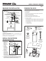
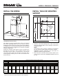
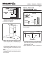
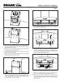
MODELS EW5630SS • EW5636SS
Page 1
Chimney
Range Hood
READ AND SAVE THESE INSTRUCTIONS
FOR DOMESTIC COOKING ONLY
WARNING
WARNING
TO REDUCE THE RISK OF FIRE, ELECTRIC SHOCK, OR
INJURY TO PERSON(S) OBSERVE THE FOLLOWING:
1. Usethisunitonlyinthemannerintendedbythemanufacturer.
If you have questions, contact the manufacturer at the
addressortelephonenumberlistedinthewarranty.
2. Beforeservicingorcleaningunit,switchpoweroffatservice
panel and lock service disconnecting means to prevent
power from being switch on accidentally.When the service
disconnecting means cannot be locked, securely fasten
a prominent warning device, such as a tag, to the service
panel.
3. Installation work and electrical wiring must be done by
qualifiedpersonnelinaccordancewithallapplicablecodes
and standards, including fire-rated construction codes and
standards.
4. Providesufficientairforpropercombustionandexhaustingof
gasesthroughtheflue(chimney)offuelburningequipment
to prevent backdrafting. Follow the combustion equipment
standards such as those published by the National Fire
Protection Association (NFPA), the American Society for
Heating, Refrigeration and Air Conditioning Engineers
(ASHRAE)andlocalcodes.
5.Thisproductmayhavesharpedges.Becarefultoavoidcuts
andabrasionsduringinstallationandcleaning.
6..When cutting or drilling into wall or ceiling, do not damage
electricalwiringandotherhiddenutilities.
7. Ductedfansmustalwaysbeventedtotheoutdoors.
8. Useonlymetalductwork.
9. Donotusethisunitwithanyothersolid-statespeedcontrol
device.
10.Thisunitmustbegounded.
2. NEVERPICKUPAFLAMINGPAN–Youmaybeburned.
3. DONOTUSEWATER,includingwetdishclothsortowels–a
violentsteamexplosionwillresult.
4. UseanextinguisherONLYif:
A. YouknowyouhaveaClassABCextinguisher,andyou knowhowtooperateit.
B. Thefireissmallandcontainedintheareawhereitstarted.
C. Thefiredepartmentisbeingcalled.
D. Youcanfightthefirewithyourbacktoanexit.
*Basedon“KitchenFiresafetyTips”publishedbyNFPA
TO REDUCE THE RISK OF A RANGE TOP GREASE FIRE:
a) Never leave surface units unattended at high settings.
Boilovers cause smoking and greasy spillovers that may
ignite.Heatoilsslowlyonlowormediumsettings.
b)Always turn hood ON when cooking at high heat or when
flambéing food (i.e. Crêpes Suzette, Cherries Jubilee,
PeppercornBeefFlambé).
c) Clean ventilating fans frequently. Grease should not be
allowedtoaccumulateonfanorfilters.
d)Use proper pan size.Always use cookware appropriate for
thesizeofthesurfaceelement.
TO REDUCE THE RISK OF INJURY TO PERSON(S) IN THE
EVENT OF A RANGE TOP GREASE FIRE, OBSERVE THE
FOLLOWING*:
1. SMOTHER FLAMES with a close-fitting lid, cookie sheet,
or metal tray, then turn off the burner. BE CAREFUL
TO PREVENT BURNS. IF THE FLAMES DO NOT GO
OUT IMMEDIATELY, EVACUATE AND CALL THE FIRE
DEPARTMENT.
CAUTION
1. Forindooruseonly.
2. For general ventilating use only. Do not use to exhaust
hazardousorexplosivematerialsandvapors.
3. Toavoidmotorbearingdamageandnoisyand/orunbalanced
impeller,keepdrywallspray,constructiondust,etc.offpower
unit.
4. Your hood motor has a thermal overload which will
automatically shut off the motor if it becomes overheated.
The motor will restart when it will cool down. If the motor
continuestoshutoffandrestart,havethehoodserviced.
5. ThebottomofthehoodMUSTNOTBELESSthan24”above
cooktop.
6. Twoinstallersarerecommendedbecauseofthesizeofthis
hood.
7. Toreduceriskoffireandtoproperlyexhaustair,besureto
ductairoutside.Donotexhaustairintospaceswithinwalls
orceilingsorintoattics,crawlspaces,orgarages.
8. Becarefulwheninstallingthedecorativeflueandhood,they
mayhavesharpedges.
9. Thishoodisnotintendedtobeusedasashelf.
10.Please read specification label on product for further
informationandrequirements.
Register your product online at: www.broan.com
Installer: Leave this manual
with the homeowner.
Homeowner: Operation and Maintenance
instructions on page 2.
MODELS EW5630SS • EW5636SS
Page 2
MEASURE THE INSTALLATION
PREPARE THE HOOD
Unpackhoodandcheckcontents.Youshouldreceive:
ROOF CAP
1-HoodAssembly
ROUND ELBOW
6” ROUND DUCT
DECORATIVE FLUE
3¾” FROM WALL
WALL CAP
HOOD MOUNTING
BRACKET
TO CENTER LINE
OF DUCT
DECORATIVE FLUE
HOOD
1-DecorativeFlueAssembly(consistingofupperandlowerflue)
1-UpperFlueMountingBracket
1-AluminumGreaseFilter(installedonhood)
2-35WR16GU10HalogenLamps(installedonhood)
1-PartsBagcontaining:
15 7/8” TO CENTER
OF UPPER BRACKET
HOLES
3½”
2” TO CENTER
24” TO 36” ABOVE
1-GlassCanopy
OF LOWER HOOD
CHASIS HOLES
6- MountingScrews(4mmx38mmCrossRecessedPanHead)
2- MountingScrews(4mmx12mmCrossRecessedPanHead)
4- MountingScrews(.188x.250CrossRecessedFlatHead)
1- SuctionCupTool
1- InstallationManual
COOKING SURFACE
2 MOUNTING
SCREWS
(4mm x 12mm
Cross Recessed
Pan Head)
UPPER
FLUE MOUNTING
BRACKET
DECORATIVE
FLUE
ASSEMBLY
The minimum hood distance above cooktop MUST NOT BE
LESSthan24”.
A maximum of 36” above cooktop is recommended for best
captureofcookingimpurities.
Distances over 36” are at the installer and users discretion;
providingthattheceilingheightpermits
INSTALL THE DUCTWORK
(Ducted Hoods Only)
1. Decidewhere
ROOF CAP
theductwork
6”
willrun
ROUND DUCT
betweenthe
hoodandthe
outside.
2. Astraight,
shortduct
DECORATIVE
WALL CAP
FLUE
runwillallow
thehoodto
performmost
HOOD
ROUND
efficiently.
ELBOW
3. Longduct
runs,elbows
andtransitions
willreducethe
24” TO 36” ABOVE
performanceof
COOKING SURFACE
thehood.Use
asfewofthemaspossible.Largerductingmayberequired
forbestperformancewithlongerductruns.
4. Installwallcaporroofcap.Connectroundmetalductwork
tocapandworkbacktowardsthehoodlocation.Useduct
tapetosealthejointsbetweenductworksections.
4 MOUNTING
SCREWS
(.188 x .250
Cross Recessed
Flat Head)
6 MOUNTING
SCREWS
(4mm x 38mm
Cross Recessed
Pan Head)
GLASS
CANOPY
BULB
SUCTION
CUP TOOL
HOOD
ASSEMBLY
MODELS EW5630SS • EW5636SS
Page 3
INSTALL THE WIRING
INSTALL THE HOOD MOUNTING
SUPPORT
HO
CENTEOD
RLINE
5”
MAX.
CL
12”
MAX.
4 7/16 ”
13 7/8 ”
A
15¼”
3”
4mm x 38mm
SCREWS
HERE
SEE
CHART
BELOW
24
ABOV ” TO 36”
E COO
KTOP
36” HIGH COOKTOP
GROUNDINGINSTRUCTIONS
Thisappliancemustbegrounded.Intheeventofanelectrical
short circuit, grounding reduces the risk of electric shock by
providinganescapewirefortheelectriccurrent.Thisappliance
isequippedwithacordhavingagroundingwirewithagrounding
plug.The plug must be plugged into an outlet that is properly
installedandgrounded.
Position the electrical outlet within the space covered by the
decorative flue and where it will not interfere with the round
duct. Make sure the outlet is no further than 12” from the top
ofthehoodchasisandthattheoutletdoesnotinterferewitha
mounting bracket fastening area or where the decorative flue
touchesthewall.
24"
Ceiling
Height
8 Feet
9 Feet
25"
26"
27"
28"
1. Construct wood wall framing that is flush with interior
surfaceofwallstuds.Makesuretheframingiscenteredover
installationlocation.
NOTE
Hood distance above cooktop is: Minimum 24”, Maximum
36”.9-ft.and10-ft.ceilingsrequireFlueExtension,Model
FXNE56SS (purchase separately). See chart below for
additionalinstallationheightinformation.
2. Afterwallsurfaceisfinished,fasten(2)4mmx38mmscrews
atthelocationsshownabove.DONOTTIGHTENscrewsall
theway.
Desired Hood Distance (Above 36" High Cooktop)
29"
30"
31"
32"
33"
34"
35"
36"
Upper Mounting Screws Location (Distance above 36" High Cooktop - Dimension “A”)
39-7/8"
40-7/8"
41-7/8"
42-7/8"
43-7/8"
44-7/8"
45-7/8"
9 Feet
with
39-7/8"
FXNE56SS
40-7/8"
41-7/8"
42-7/8"
43-7/8"
44-7/8"
45-7/8"
10 Feet
with
39-7/8"
FXNE56SS
40-7/8"
41-7/8"
42-7/8"
43-7/8"
44-7/8"
45-7/8"
* Not recommended for non-ducted configuration
** Non-duct recirculation louvers will be exposed in ducted configuration
46-7/8"
**46-7/8"
47-7/8"
**47-7/8"
48-7/8"
**48-7/8"
*49-7/8"
49-7/8"
*50-7/8"
50-7/8"
*51-7/8"
51-7/8"
46-7/8"
47-7/8"
48-7/8"
49-7/8"
50-7/8"
51-7/8"
MODELS EW5630SS • EW5636SS
Page 4
INSTALL THE HOOD
Ceiling
(Ducted Hoods Only)
Center of
installation
Flush with
the ceiling
C
L
Upper flue mounting
bracket slots
1. Centerthefluemountingbracketoverthehoodlocationand
flush with the ceiling. Secure the upper flue bracket to the
wallusing(2)#Xx1½”mountingscrews.
6. Alignthekeyholeslotsonthehoodwiththemountingscrews
thatwerepartiallytightenedintothewallframing.Ensurethat
hoodisseatedentirelyonmountingscrewsandthathoodis
level.Thentightenscrewscompletely.
2. Tightenthescrewscompletely.Makesurethatthebracketis
tightagainstthewallandceiling.Note:Drywallanchorsmay
beneeded(notincluded).
3. Remove the protective plastic film covering the decorative
flueandthehoodatthistime.
7. Install(2)4mmx38mmlongscrewsintotheholesinsidethe
hoodandtightenthemsecurely
4. Remove(3)screwsholdingelectronicsmountingbracketto
hood. Rotate bracket 180 degrees and re-attach bracket to
hoodwithsame(3)screws.
5. Removethegreasefilterbypullingdownthemetallatchtab
andtiltingfilterdownwardtoremove
8. Carefullyplaceglasscanopyontopofthehood.Alignnuts
onglasscanopywithholesinsidethehood.Attachcanopy
with(4).188”x.250”longflatheadscrews.Tightenscrews
securelybutDONOTOVERTIGHTEN.
9. Reinstall grease filter by aligning side filter tab with slots
in the hood. Pull down the metal latch tab, push filter into
position and release. Make sure filter is securely engaged
afterinstallation.
MODELS EW5630SS • EW5636SS
Page 5
6” ROUND
STEEL DUCT
DUCT LENGTH
INSTALL THE HOOD
(Non-Ducted Hoods Only)
NON-DUCT KIT MODEL RKE56 CONTENTS
DECORATIVE
FLUE
NON-DUCTED
RECIRCULATION
FILTERS
NON-DUCT PLENUM
ASSEMBLY
10. Measureandinstallsteelductworktohoodductconnector
andductworkrough-inonceilingorwall.Useducttapeto
makealljointssecureandairtight.
11. Plugpowercordintowalloutlet.
4 MOUNTING
SCREWS
(3/8” Long
Round Head)
FILTER
TRAY
2 MOUNTING
SCREWS
(1-1/2” Long)
FLEXIBLE DUCT
NOTE
Non-ductedinstallationsrequireNon-DuctKit,ModelRKE56
(purchaseseparately).
Ceiling
Center of
installation
Flush with
the ceiling
C
L
Upper flue mounting
bracket slots
12. Slide the upper decorative flue section into the lower
decorativefluesection.NOTEForductedapplications,the
louvers on the upper flue should be hidden by sliding the
louversdown,insideofthelowerflue.
13. Carefully place the upper/lower flue assembly into the
recessedareaofthehood.
14. Slidetheupperflueupwarduntilitisalignedwithitsmounting
bracket.The bracket should be inside the flue. Secure the
upperfluetotheupperfluemountingbracketusing(2)4mm
x12mmmountingscrews.
NOTE
9-10 ft. ceilings require Flue Extension Model FXNE56SS
(purchase separately). Discard the upper and lower flues
suppliedwithyourhoodandreplacethemwithFlueExtension
ModelFXNE56SS.
1. Centerthenon-ductplenumoverthehoodlocationandflush
withtheceiling.Securethenon-ductplenumtothewallusing
(2)#Xx1½”mountingscrews.
2. Tightenthescrewscompletely.Makesurethatthenon-duct
plenumistightagainstthewall.
3. Remove damper flaps from damper / duct connector and
discardflaps
MODELS EW5630SS • EW5636SS
Page 6
9. Install(2)4mmx38mmlongscrewsintotheholesinsidethe
hoodandtightenthemsecurely
4. Remove(3)screwsholdingelectronicsmountingbracketto
hood. Rotate bracket 180 degrees and re-attach bracket to
hoodwithsame(3)screws.
5. Removethegreasefilterbypullingdownthemetallatchtab
andtiltingfilterdownwardtoremove
6. Remove the protective plastic film covering the decorative
flueandthehoodatthistime.
10. Carefullyplaceglasscanopyontopofthehood.Alignnuts
onglasscanopywithholesinsidethehood.Attachcanopy
with(4).188”x.250”longflatheadscrews.Tightenscrews
securelybutDONOTOVERTIGHTEN.
7. Removethegreasefilterbypullingdownthemetallatchtab
andtiltingfiltersdownwardtoremove.
11. Attachfiltertraytobottomofhoodusing(4)mountingscrews.
8. Alignthekeyholeslotsonthehoodwiththemountingscrews
thatwerepartiallytightenedintothewallframing.Ensurethat
hoodisseatedentirelyonmountingscrewsandthathoodis
level.Thentightenscrewscompletely.
12.Snap in 2-non-duct filters into filter trays by engaging filter
tabonside,rotatingupwardtoengagefilterclips.
13. Reinstall grease filter by aligning rear filter tab with slots
in the hood. pull down the metal latch tab, push filter into
position and release. Make sure filter is securely engaged
afterinstallation.
MODELS EW5630SS • EW5636SS
Page 7
OPERATION
NON-DUCT
6” ROUND PLENUM
FLEXIBLE
METAL DUCT
DUCT LENGTH
AlwaysturnthehoodONbeforecookinginordertoestablishanair
flowinthekitchen.Afterturningofftherange,letthehoodrunfora
fewminutestocleartheair.
Operatethehoodasfollows:
OFF
DECORATIVE
FLUE
OFF
13. Measure and install section of flexible metal ductwork
(includedwithRKE56)tohoodductconnectorandbottom
ofnon-ductplenum.Useducttapetomakealljointssecure
andairtight.
CAUTION
Donotuseplasticduct.
14. Plugpowercordintowalloutlet.
FAN
DELAY
OFF LIGHT
FANSPEED
LEDINDICATORS
TurnsthefanOFF
FAN(1-PushbuttonSwitch,3-FanSpeeds)
TurnsthefanONtothelastselectedspeed,andactivatesablueLED
indicatingthefanspeedsetting.PressingtheFANbuttonasecond
timewillindexthefanspeedandLEDindicatortothenexthighest
setting.PressingtheFANbuttonwhenthefanisatthehighestspeed
settingwillindexthefanandLEDindicatortothelowestsetting.
DELAY-OFF (10 Minute Delay-OFF)
Activates the 10 minute delay off feature when the fan is ON (any
speed).Whenactivated,theblueLEDindicatorabovetheselected
speedsettingwillblink.ThehoodfanwillautomaticallyturnOFFafter
10minuteshaselapsed.TheDELAY-OFFbuttoncanbepressedat
anytimeduringthe10minutecountdowntoturnoffthefeature.
LIGHT (1-Pushbutton Switch, 3-Light Intensities)
TurnsthelightsONtothelowestintensity.PressingtheLIGHTbutton
asecondtimewillindexthelightintensitytothenexthighestlevel.
PressingtheLIGHTbuttonwhenthelightsareatthehighestintensity
willturnthelightsoff.
FILTER CHANGE INDICATION
After30hoursoffanoperation,thethreeblueLEDindicatorswillblink
simultaneously, indicating that it is time to clean the grease filters.
Toresetthefiltercleantimer,pressandholdtheOFFbuttonfor3
seconds.TheblinkingLEDindicatorswillturnoff.
HEAT SENTRY SYSTEM
This range hood is equipped with a standard Heat Sentry system
thatmonitorsexcessivetemperatureandautomaticallyturnsthefan
speedonHIGH.
15. Slide the upper decorative flue section into the lower
decorativefluesection.NOTEFornon-ductedapplications,
theupperflueshouldbeorientedsothelouversaretowards
theceiling.
16. Carefully place the upper/lower flue assembly into the
recessedareaofthehood.
17. Slidetheupperflueupwarduntilitisalignedwiththenonductplenum.Thenon-ductplenumshouldbeinsidetheflue.
Securetheupperfluetothenon-ductplenumusing(2)4mm
x12mmmountingscrews.
NOTE
9-10ft.ceilingsrequireFlueExtensionModelFXNE56SS
(purchaseseparately).Discardtheupperandlowerflues
suppliedwithyourhoodandreplacethemwithFlue
ExtensionModelFXNE56SS.
1) If the fan is ON, the Heat Sentry system will increase the fan
setting to it’s highest speed when the temperature is elevated.
The blue indicator for fan speed (3) will illuminate and blink at
ahighrate,indicatingthattheheatsentryfunctionisactivated.
Oncethetemperaturehasreduced,theHeatSentrysystemwill
changethefanspeedtotheoriginalsetting.
2)IfthefanisOFF,theHeatSentrysystemwillautomaticallyturn
thefanontoit’shighestspeedwhenthetemperatureisabove
normal.Theblueindicatorforfanspeed(3)willilluminateand
blink at a high rate, indicating that the heat sentry function is
activated.Afterthetemperaturehasloweredtonormal,thefan
willturnoff.
FUSES
TheRangeHoodControlBoardcontainsaMainFusetoprotectthe
controlsfrompowersurges.Newfusescanbepurchasedatalocal
electronicsupplystore.Use5A,120V,5mmdiameter,20mmlong,
fast-acting,cartridge-typefuses.
MODELS EW5630SS • EW5636SS
Page 8
Toreplaceafuse(byqualifiedperson(s):
1. Disconnectpoweratserviceentrance.
2. Removedecorativeflues.
3. Removecontrolcover.
4. Removeandinspectfuse.
LIGHT BULBS
SUCTION
CUPTOOL
MAKE-UP AIR DAMPER
The hood is compatible with Broan Make-Up Air Damper Model
MD6TorModelMD8T(optional).Purchaseseparately.
MAKE-UP AIR DAMPER
MAKE UP DAMPER CONNECTION
(switched low voltage)
HALOGEN
BULB
20 GAUGE BELL WIRE FOR LOW
VOLTAGE CONNECTION ON
TOP OF HOOD
24V
TRANSFORMER
(INCLUDED)
HOOD
GRD
120 VAC
60 HZ
DRY CONTACT
TERMINAL
BUSHING
FOR LOW
VOLTAGE
CONNECTION
Make the connection to the Make-UpAir Damper with low voltage
wiring,asshown.SeeMake-UpAirDamperinstructionsforadditional
information.
REMOTE CONTROL
ThehoodiscompatiblewithBroanRFRemoteControlModelBCR1
(optional).Purchaseseparately.
(1)
PUSHIN
(2)
ROTATE
CLOCKWISE
WARNING
Bulbsmaybehot.Alwaysallowbulbstocooldownbeforeremoving
them.
Use(2)HalogenBulbs(includedwithhood)-120V,35W,shielded
halogenbulbs-MR16withGU10base.
NOTE
SuctionCupTool(includedwithhood)canbeusedtoinstalland
removelightbulbs.Alignpinsonbulbwithlargediameteropening
onsocket,thenpushbulbintowardshoodandrotateclockwise
untilfirmlyseated.Thepositionofthebulbsocket(depth)is
adjustableandmayrequireadjustmentwhen:a)certainbrandsof
bulbsaredifficulttoinstall.b)thebulbprotrudestoofarbelowthe
lightpanel.
TolinktheBCR1remotecontrolwiththehood,pressandholdthe
LIGHTbuttonfor3-seconds.
TheblueLEDindicatorswillturnonandoffinsuccessiontoindicate
thehoodisinRFlinkingmode.Wheninthelinkingmode,pressany
keyontheRFremote.Anaudiblebeepwillbeheardatthehood,and
thehoodLED’swillstopblinkingifasuccessfullinkisaccomplished.
Iftheremotecontroldidnotsuccessfullylinkwiththehood,thelinking
modewillbedeactivatedafter12seconds,andtheLED’swillstop
thesequentialblinking.RefertotheBCR1instructionsforadditional
information.
CLEANING & MAINTENANCE
Forperformance,appearance,andhealthreasons,cleanfilter,fan
andgrease-ladensurfaces.Useonlyacleanclothandmilddetergent
solutiononstainlessandpaintedsurfaces.
Clean all-metal filters in the dishwasher using a non-phosphate
detergent. Discoloration of the filter may occur if using phosphate
detergents,orasaresultoflocalwaterconditions-butthiswillnot
affect filter performance. This discoloration is not covered by the
warranty.
Clean the non-duct recirculating filter surfaces frequently with a
dampclothandamilddetergent.DONOTimmersefiltersinwater
orputindishwasher.Changethenon-ductrecirculatingfiltersevery
6months.Forreplacementnon-ductrecirculatingfilters-purchase
S99010365orModelFILTERE56.
Themotorispermanentlylubricatedandneverneedsoiling.Ifthe
motorbearingsmakeexcessiveorunusualnoise,replacetheblower
assemblywithanexactservicereplacement.
LAMPSOCKET
BRACKET
LIGHT
PANEL
SCREWS
Tochangethedepthofbulbsockets:
- Remove2screwsonlightpanel–setscrewsaside
- RemoveLightPanel.
- Loosen2ScrewsholdingLampSocketBrackettoLightPanel.
- Adjustsocket/brackettodesireddepth.
- Re-tightenscrewssecurely.
- Re-attachlightpanelwith2screwsthatwerepreviouslysetaside.
MODELS EW5630SS • EW5636SS
Page 9
SERVICE PARTS
KEY
PART NO.
DESCRIPTION
1
S99527442
DecorativeUpperandLowerFlues
QTY.
1
2
S99527443
Motor/BlowerAssembly
1
3
S99527444
LightSocket(includesmountinghardware)
2
4
S99527445
LightSocketBracket(includesmountinghardware)
2
5
S99527446
UserInterfaceAssembly
1
6 S99527447
UserInterfaceCable
1
7 S99527449
ControlBoard
1
8 S99527450
ControlEnclosure
1
9 S99527451
LightPanel
1
10
S97010367
AluminumGreaseFilter
1
11
S99527457
Non-DuctFilterTray
1
12
S97010365
Non-DuctRecirculationFilters(pair)
1
13
S99527455
CurvedGlassPlate(EW5630SS)
1
S99527456
CurvedGlassPlate(EW5636SS)
1
14
S99527461
DamperAssembly
1
15
S99527462
6”Dia.ExpandableFlexibleAluminumDuct
1
16
S99527463
Non-DuctPlenumAssembly
1
17
S99527466
UpperFlueMountingBracket
1
18
S99526798
35WMR16GU10HalogenLamp
2
19
S99527468
Capacitor
1
* S99527470
HeatSensor
1
* S99527471
Fuse
1
* S99527472
PartsBag
1
* S99527481
UserInterfaceButton,4-pack
4
17
1
16
14
8
8
13
4
3
18
18
9
2
11
12
WARRANTY
7
19
5
*Notshown
Replacementpartscanbeorderedonourwebsite:
www.broan.com
15
1
12
10
BROAN-NUTONE ONE YEAR LIMITED WARRANTY
Broan-NuTone warrants to the original consumer purchaser of its products that such products will be free from defects in materials or workmanship for a period of one year from the date of original
purchase. THERE ARE NO OTHER WARRANTIES, EXPRESS OR IMPLIED, INCLUDING, BUT NOT LIMITED TO, IMPLIED WARRANTIES OF MERCHANTABILITY OR FITNESS FOR A PARTICULAR
PURPOSE.
During this one-year period, Broan-NuTone will, at its option, repair or replace, without charge, any product or part which is found to be defective under normal use and service.
THIS WARRANTY DOES NOT EXTEND TO FLUORESCENT LAMP STARTERS, TUBES, HALOGEN AND INCANDESCENT BULBS, FUSES, FILTERS, DUCTS, ROOF CAPS, WALL CAPS AND OTHER ACCESSORIES FOR DUCTING. This warranty does not cover (a) normal maintenance and service or (b) any products or parts which have been subject to misuse, negligence, accident, improper maintenance
or repair (other than by Broan-NuTone), faulty installation or installation contrary to recommended installation instructions.
The duration of any implied warranty is limited to the one-year period as specified for the express warranty. Some states do not allow limitation on how long an implied warranty lasts, so the above
limitation may not apply to you.
BROAN-NUTONE’S OBLIGATION TO REPAIR OR REPLACE, AT BROAN-NUTONE’S OPTION, SHALL BE THE PURCHASER’S SOLE AND EXCLUSIVE REMEDY UNDER THIS WARRANTY. BROAN-NUTONE SHALL NOT BE LIABLE FOR INCIDENTAL, CONSEQUENTIAL OR SPECIAL DAMAGES ARISING OUT OF OR IN CONNECTION WITH PRODUCT USE OR PERFORMANCE. Some states do not allow
the exclusion or limitation of incidental or consequential damages, so the above limitation or exclusion may not apply to you.
This warranty gives you specific legal rights, and you may also have other rights, which vary from state to state. This warranty supersedes all prior warranties.
To qualify for warranty service, you must (a) notify Broan-NuTone at the address or telephone number below, (b) give the model number and part identification and (c) describe the nature of any defect
in the product or part. At the time of requesting warranty service, you must present evidence of the original purchase date.
Broan-NuTone LLC, 926 W. State Street, Hartford, Wisconsin 53027 www.broan.com 800-558-1711
Broan-NuTone Canada, Inc., 1140 Tristar Drive, Mississauga, Ontario L5T 1H9 www.broan.ca 877-896-1119
99527439A