1
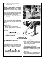
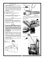
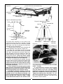
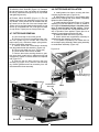
BUSH HOG
®
GEARDRIVE
HAY MOWERS
SERIES GHM 700, GHM 800, GHM 900
GHM 1800 & GHM 1900
Operator’s Manual
ASSEMBLY ● OPERATION ● MAINTENANCE
1297
$4.00
Part No. 99707
CONGRATULATIONS!
You have invested in the best implement of its type on the market today.
The care you give your Bush Hog implement will greatly determine your satisfaction
with its performance and its service life. We urge a careful study of this manual to provide
you with a thorough understanding of your new implement before operating, as well as
suggestions for operation and maintenance.
If your manual should become lost or destroyed, Bush Hog will be glad to provide you with
a new copy. Order from Bush Hog, P. O. Box 1039, Selma, Alabama 36702-1039. Most of our
manuals can also be downloaded from our website at www.bushhog.com.
As an authorized Bush Hog dealer, we stock genuine Bush Hog parts which are
manufactured with the same precision and skill as our original equipment. Our trained
service personnel are well informed on methods required to service Bush Hog equipment,
and are ready and able to help you.
Should you require additional information or assistance, please contact us.
YOUR AUTHORIZED
BUSH HOG DEALER
BECAUSE BUSH HOG MAINTAINS AN ONGOING
PROGRAM OF PRODUCT IMPROVEMENT, WE
RESERVE THE RIGHT TO MAKE IMPROVEMENTS IN
DESIGN OR CHANGES IN SPECIFICATIONS WITHOUT INCURRING ANY OBLIGATION TO INSTALL
THEM ON UNITS PREVIOUSLY SOLD.
BECAUSE OF THE POSSIBILITY THAT SOME
PHOTOGRAPHS IN THIS MANUAL WERE TAKEN OF
PROTOTYPE MODELS, PRODUCTION MODELS MAY
VARY IN SOME DETAIL. IN ADDITION, SOME
PHOTOGRAPHS MAY SHOW SHIELDS REMOVED
FOR PURPOSES OF CLARITY. NEVER OPERATE
THIS IMPLEMENT WITHOUT ALL SHIELDS IN PLACE.
GHM HAY MOWER
TABLE OF CONTENTS
SECTION/PARA
SECTION/PARA
PAGE
PAGE
IV. MAINTENANCE.........................................12
4-1 Maintenance Check List ......................12
4-2 Lubrication ...........................................13
4-3 Blade Replacement .............................14
4-4 Belt Adjustment....................................14
4-5 Belt Replacement ................................14
4-6 Spindle Housing Removal and
Reassembly .........................................14
4-7 Cutter Bar Removal .............................15
4-8 Cutter Bar Installation ..........................16
4-9 Troubleshooting ...................................17
V. ASSEMBLY................................................19
Safety Decals.............................................21
Torque Specifications.................................23
Warranty.......................................................3
Dealer Preparation Check List .....................4
Safety Precautions.......................................5
Federal Laws and Regulations ....................6
I. INTRODUCTION & DESCRIPTION ............7
1-1 Introduction ............................................7
1-2 Description.............................................7
II. PREPARATION FOR USE...........................8
III. OPERATING INSTRUCTIONS ..................10
3-1 General Safety.....................................10
3-2 Cutting Height ......................................10
3-3 Transporting.........................................10
3-4 Breakaway Latch .................................10
3-5 Operation .............................................11
3-6 Swath Board .......................................11
3-7 Cutter Bar Helper Spring
Adjustment ...........................................12
3-8 Unhitching From Tractor and Storage........12
RETAIL CUSTOMER’S RESPONSIBILITY
UNDER THE BUSH HOG WARRANTY
It is the Retail Customer and/or Operator’s responsibility to read the Operator’s Manual, to
operate, lubricate, maintain and store the product in accordance with all instructions and
safety procedures. Failure of the operator to read the Operator’s Manual is a misuse of this
equipment.
It is the Retail Customer and/or Operator’s responsibility to inspect the product and to have
any part(s) repaired or replaced when continued operation would cause damage or excessive wear to other parts or cause a safety hazard.
It is the Retail Customer’s responsibility to deliver the product to the authorized Bush Hog
Dealer, from whom he purchased it, for service or replacement of defective parts which are
covered by warranty. Repairs to be submitted for warranty consideration must be made within forty-five (45) days of failure.
It is the Retail Customer’s responsibility for any cost incurred by the Dealer for traveling to or
hauling of the product for the purpose of performing a warranty obligation or inspection.
UNDERSTAND SIGNAL WORDS
DANGER: Indicates an imminently
hazardous situation which, if not avoided, will result in death or serious injury.
This signal word is to be limited to the
most extreme situations.
WARNING: Indicates a potentially
hazardous situation which, if not
avoided, could result in death or
serious injury.
2
CAUTION: Indicates a potentially hazardous situation which, if not avoided,
may result in minor or moderate injury. It
may also be used to alert against
unsafe practices.
BUSH HOG®
LIMITED WARRANTY
✯✯✯✯✯✯✯✯✯✯✯✯✯✯✯✯✯✯✯✯✯✯✯✯✯✯✯✯✯✯✯
Bush Hog warrants to the original purchaser of any new Bush Hog equipment, purchased from an
authorized Bush Hog dealer, that the equipment be free from defects in material and workmanship for a period
of one (1) year for non-commercial, state, and municipalities’ use and ninety (90) days for commercial use from
date of retail sale. The obligation of Bush Hog to the purchaser under this warranty is limited to the repair or
replacement of defective parts.
Replacement or repair parts installed in the equipment covered by this limited warranty are warranted
for ninety (90) days from the date of purchase of such part or to the expiration of the applicable new equipment warranty period, whichever occurs later. Warranted parts shall be provided at no cost to the user at an
authorized Bush Hog dealer during regular working hours. Bush Hog reserves the right to inspect any equipment or parts which are claimed to have been defective in material or workmanship.
DISCLAIMER OF IMPLIED WARRANTIES & CONSEQUENTIAL DAMAGES
Bush Hog’s obligation under this limited warranty, to the extent allowed by law, is in lieu of all warranties, implied or expressed, INCLUDING IMPLIED WARRANTIES OF MERCHANTABILITY AND FITNESS
FOR A PARTICULAR PURPOSE and any liability for incidental and consequential damages with respect to
the sale or use of the items warranted. Such incidental and consequential damages shall include but not be
limited to: transportation charges other than normal freight charges; cost of installation other than cost
approved by Bush Hog; duty; taxes; charges for normal service or adjustment; loss of crops or any other loss of
income; rental of substitute equipment, expenses due to loss, damage, detention or delay in the delivery of
equipment or parts resulting from acts beyond the control of Bush Hog.
THIS LIMITED WARRANTY SHALL NOT APPLY:
1. To vendor items which carry their own warranties, such as engines, tires, and tubes.
2. If the unit has been subjected to misapplication, abuse, misuse, negligence, fire or other accident.
3. If parts not made or supplied by Bush Hog have been used in connection with the unit, if, in the sole judgement of Bush Hog such use affects its performance, stability or reliability.
4. If the unit has been altered or repaired outside of an authorized Bush Hog dealership in a manner
which, in the sole judgement of Bush Hog, affects its performance, stability or reliability.
5. To normal maintenance service and normal replacement items such as gearbox lubricant, hydraulic fluid,
worn blades, or to normal deterioration of such things as belts and exterior finish due to use or
exposure.
6. To expendable or wear items such as teeth, chains, sprockets, belts, springs and any other items that in the
company’s sole judgement is a wear item.
NO EMPLOYEE OR REPRESENTATIVE OF BUSH HOG IS AUTHORIZED TO CHANGE THIS LIMITED WARRANTY IN ANY WAY OR GRANT ANY OTHER WARRANTY UNLESS SUCH CHANGE IS MADE
IN WRITING AND SIGNED BY BUSH HOG’S SERVICE MANAGER, POST OFFICE BOX 1039, SELMA,
ALABAMA 36702-1039.
✯✯✯✯✯✯✯✯✯✯✯✯✯✯✯✯✯✯✯✯✯✯✯✯✯✯✯✯✯✯✯
Record the model number, serial number and date
purchased. This information will be helpful to your
dealer if parts or service are required.
MODEL NUMBER
MAKE CERTAIN THE WARRANTY REGISTRATION
CARD HAS BEEN FILED WITH BUSH HOG/
SELMA, ALABAMA
SERIAL NUMBER
DATE OF RETAIL SALE
3
DEALER PREPARATION CHECK LIST
GHM HAY MOWER
BEFORE DELIVERING MACHINE — The following check list should be completed.
Use the Operator’s Manual as a guide.
❒
❒
❒
❒
❒
❒
❒
❒
1.
Assembly completed.
2.
Gearbox filled with oil.
3.
All fittings lubricated.
4.
All shields in place and in good condition.
5.
All fasteners torqued to specifications given in Torque Chart.
6.
All decals in place and readable. (See decal page.)
7.
Overall condition good (i.e. paint, welds)
8.
Operators manual has been delivered to owner and he has been instructed
on the safe and proper use of the mower.
Dealer’s Signature
Purchaser’s Signature
THIS CHECKLIST TO REMAIN IN OWNER’S MANUAL
It is the responsibility of the dealer to complete the procedures listed
above before delivery of this implement to the customer.
4
IMPORTANT SAFETY PRECAUTIONS
This symbol is used to call attention to safety precautions that should be followed by
the operator to avoid accidents. When you
see this symbol, carefully read the message
that follows and heed its advice. Failure to
comply with safety precautions could result
in serious bodily injury.
In addition to the design and configuration of equipment, hazard control and accident prevention are dependent upon the awareness, concern, prudence and proper training of personnel in the operation, transport,
maintenance and storage of equipment. Lack of attention to safety can result in accident, personal injury,
reduction of efficiency and worst of all—loss of life. Watch for safety hazards and correct deficiencies promptly. Use the following safety precautions as a general guide to safe operations when using this machine.
Additional safety precautions are used throughout this manual for specific operating and maintenance procedures. Read this manual and review the safety precautions often until you know the limitations.
1.
Read the Operator’s Manual. Failure to read the Operator’s Manual is considered a misuse of this equipment.
2.
Become familiar with all the machine’s controls and all the caution, warning and danger decals affixed
to the machine before attempting to start or operate.
3.
Before starting or operating the machine, make a walk around inspection and check for obvious defects
such as loose mounting bolts and damaged components. Correct any deficiency before starting.
4.
Do not allow children to operate the mower. Do not allow adults to operate it without proper instruction.
5.
Do not carry passengers.
6.
Keep the area of operation clear of all persons, particularly small children and pets. The operator should
cease mowing whenever anyone comes within the operating area.
7.
Clear the work area of objects which might be picked up and thrown.
8.
Use a piece of cardboard or wood rather than hands to search for hydraulic leaks. Escaping hydraulic oil
under pressure can penetrate skin. If fluid is injected into the skin, it must be surgically removed within a
few hours by a doctor familiar with this form of injury or gangrene may result.
9.
Do not operate without all guards and shields in place and in good condition.
10. Stop PTO, lower implement to ground, place tractor transmission in neutral or park, set parking brake, stop
tractor engine, remove ignition key and wait for all motion to completely stop before leaving the tractor.
11. Keep hands and feet away from blades.
12. This mower is not to be operated in any area where people may be present unless all
sides of the unit are enclosed by a curtain guard that is in good repair.
13. Wear personal protective equipment such as, but not limited to, protection for eyes, ears, feet, hands and
head when operating or repairing the equipment. Do not wear loose clothing or jewelry that may catch on
equipment moving parts.
14. When performing adjustments or maintenance on the mower, first lower it to the ground or block it securely
at a workable height.
15. Never stand between tractor and mower while tractor is being backed to the cutter hitch.
16. Reduce speed when transporting mower to avoid bouncing and momentary loss of steering.
17. Use tractor flashing warning lights, day or night, when transporting mower on road or highways unless prohibited by law.
18. Pin transport lock to retain cutter bar in transport position.
19. Lower mower to ground before unhitching from tractor.
20. In the event that someone other than yourself will operate this equipment we firmly suggest that all
SAFETY references be discussed prior to operation.
21. It is recommended that tractor be equipped with Rollover Protective System (ROPS) enclosed cab, and a
seat belt.
5
IMPORTANT FEDERAL LAWS AND REGULATIONS* CONCERNING
EMPLOYERS, EMPLOYEES AND OPERATIONS.
*(This section is intended to explain in broad terms the concept and effect of the following federal laws and
regulations. It is not intended as a legal interpretation of the laws and should not be considered as such).
U.S. Public Law 91-596 (The Williams-Steiger Occupational and Health Act of 1970) OSHA
This Act Seeks:
“...to assure so far as possible every working man and woman in the nation safe and healthful working
conditions and to preserve our human resources...”
DUTIES
Sec. 5 (a) Each employer—
(1) shall furnish to each of his employees employment and a place of employment
which are free from recognized hazards that are causing or are likely to cause
death or serious physical harm to his employees;
(2) shall comply with occupational safety and health standards promulgated under
this Act.
(b) Each employee shall comply with occupational safety and health standards
and all rules, regulations and orders issued pursuant to this Act which are
applicable to his own actions and conduct.
OSHA Regulations
Current OSHA regulations state in part: “At the time of initial assignment and at least annually thereafter, the
employer shall instruct every employee in the safe operation and servicing of all equipment with which the
employee is, or will be involved.” These will include (but are not limited to) instructions to:
Keep all guards in place when the machine is in operation;
Permit no riders on equipment;
Stop engine, disconnect the power source, and wait for all machine movement to stop before
servicing, adjusting, cleaning or unclogging the equipment, except where the machine must be
running to be properly serviced or maintained, in which case the employer shall instruct employees
as to all steps and procedures which are necessary to safely service or maintain the equipment.
Make sure everyone is clear of machinery before starting the engine, engaging power, or operating
the machine.
EMPLOYEE TRACTOR OPERATING INSTRUCTIONS:
1. Securely fasten your seat belt if the tractor has a
ROPS.
5. Watch where you are going, especially at row
ends, on roads, and around trees.
2. Where possible, avoid operating the tractor near
ditches, embankments, and holes.
6. Do not permit others to ride.
7. Operate the tractor smoothly - no jerky turns,
starts, or stops.
3. Reduce speed when turning, crossing slopes, and
on rough, slick, or muddy surfaces.
8. Hitch only to the drawbar and hitch points recommended by tractor manufacturers.
4. Stay off slopes too steep for safe operation.
9. When tractor is stopped, set brakes securely and
use park lock if available.
Child Labor Under 16 Years Old
Some regulations specify that no one under the age of 16 may operate power machinery. It is your
responsibility to know what these regulations are in your own area or situation. (Refer to U.S. Dept. of
Labor, Employment Standard Administration, Wage & Home Division, Child Labor Bulletin #102.)
6
SECTION 1
INTRODUCTION AND DESCRIPTION
1-1 INTRODUCTION
1-2 DESCRIPTION
We are pleased to have you as a Bush Hog customer. Your GHM hay mower has been carefully
designed to give maximum service with minimum
down time. This manual is provided to give you the
necessary operating and maintenance instructions for
keeping your mower in top operating condition.
Please read this manual thoroughly. Understand what
each control is for and how to use it. Observe all safety precautions decaled on the machine and noted
throughout the manual for safe operation of implement. If any assistance or additional information is
needed, contact your authorized Bush Hog dealer.
The GHM (Figure 1-1) is intended for cutting hay
and grass in a clean maintained area. A breakaway
mechanism built into the three point hitch allows cutter bar to pivot back if a stationary object is hit. The
cutter bar consists of individual spindle assemblies
driven from the main gearbox by a gear train. An
optional overrunning clutch is available to allow
“coast down” of blades when PTO is disengaged.
NOTE
All references made to right, left, front,
rear, top or bottom is as viewed facing the
direction of forward travel with implement
properly attached to tractor.
Figure 1-1 GHM Major Components (Safety Curtain Removed To Show Details Only)
HM 900 Shown
Curtain Support Assembly
Swathboard
Crop Divider
Helper Spring Assembly
Transport Lock
Three Point Hitch
Cutter Bar
Gearbox
Hitch Breakaway
Parking Stand
7
SECTION II
PREPARATION FOR USE
Figure 2-1 Hitch Adjustments
WARNING
TO AVOID SERIOUS INJURY OR DEATH
NEVER STAND BETWEEN TRACTOR
AND MOWER WHILE TRACTOR IS BEING
BACKED TO HITCH.
NARROW
WARNING
TO AVOID SERIOUS INJURY OR DEATH
ADDITIONAL TRACTOR FRONT BALLAST MAY BE NEEDED FOR STABLE
OPERATION AND TRANSPORT OF
MOWER. SEE TRACTOR OPERATOR’S
MANUAL
FOR
RECOMMENDED
WEIGHTS.
During mower operations, the right tractor tire should
run on stubble between the cut and uncut crop. As
shown in Figure 2-1, tractors with smaller/larger
wheel tread widths require the mower to be mounted
differently to achieve this.
STANDARD
A. Position mower hitch pins and attach mower
to tractor according to the illustration in Figure 2-1
that is closest to your situation. Hitch pins are
reversible to accommodate Cat.I or Cat. II hitches.
On larger tractors it may also be necessary to move
the right wheel inward. The STANDARD configuration will work on tractors with a maximum dimension
of 46” from centerline to outside of right tire.
46”
Max.
NOTE
If tractor is equipped with a Cat. II quick
hitch, mower must have optional bushings
installed on upper and lower lift pins as
shown in Figure 2-2. Lower lift pins must be
attached to the mower as shown in the
STANDARD configuration of Figure 2-1.
WIDE
B. Connect and/or adjust stabilizer bars, sway
blocks, sway chains, or equivalent to prevent laterql
movement of lift arms. Refer to tractor operator’s
manual.
C. Connect hydraulic hose to tractor remote
hydraulic outlet.
Figure 2-2
Hitch Pin Bushings
8
D. Attach PTO driveline to tractor 540 rpm or
1000 rpm PTO shaft. Make certain driveline is
securely connected at both ends. Attach PTO driveline shield safety chain on both the implement and
tractor ends. (Figure 2-3)
H. Check to be certain all persons are clear of
cutter bar.
I. Raise mower using tractor 3-point lift. Raise
cutter bar to transport position. When cylinder “bottoms out” hold valve open an additional 3-5 seconds
to purge air from system.
J. Pin transport lock to retain cutter bar in the
transport position. (Figure 2-6)
CAUTION
DO NOT USE A PTO SHAFT ADAPTER WITH THIS
IMPLEMENT. USE OF A PTO SHAFT ADAPTER
WILL VOID ALL WARRANTY CONSIDERATIONS.
E. Pin parking stand in work position. (Figure 2-4)
F. Adjust tractor lower lift arms so vertical main
frame is perpendicular to the ground as shown in
Figure 2-5.
G. Set tractor 3-point hitch depth control or install
the optional check chain assembly to stop with the
horizontal main frame pivot approximately 20 inches
from the ground. (Figure 2-4)
Figure 2-5
Figure 2-3
90°
Ground
Figure 2-6 Transport Lock
Fasten Shield Safety
Chains At Each End
Figure 2-4
20”
Parking Stand Stored
Ground
9
SECTION III
OPERATING INSTRUCTIONS
3-3 TRANSPORTING
3-1 GENERAL SAFETY
WARNING
TO AVOID SERIOUS INJURY OR DEATH,
DO NOT ALLOW CUTTER BAR TO CONTACT ELECTRICAL WIRES. USE CARE
WHEN PASSING BENEATH OVERHEAD
OBSTRUCTIONS.
Raise mower off ground using 3-point hitch. Fully
raise cutter bar and pin transport lock in the transport position. (Figure 2-6) Place parking stand in the
work position as shown in Figure 2-4. Make certain
slow moving vehicle (SMV) sign mounted on rear
shield is clean and in good condition. When transported on roads or highways, day or night, use tractor flashing warning lights unless prohibited by law.
Do not exceed 15 mph.
Only qualified people familiar with this operator’s
manual should operate this machine. Operator
should wear hard hat, safety glasses and safety
shoes. The operator should read, understand and
practice all safety messages shown on the caution,
warning and danger decals affixed to the mower to
avoid serious injury or death. It is recommended that
tractor be equipped with Rollover Protective System
(ROPS) and a seat belt be used. Before beginning
operation, clear work area of any objects that may
be picked up and thrown. Check for ditches, stumps,
holes or other obstacles that could upset tractor or
damage mower. Always turn off tractor engine, set
parking brake, lower mower to ground and allow
blades to come to a complete stop before leaving
tractor operator’s seat.
3-4 BREAKAWAY LATCH
3-2 CUTTING HEIGHT
IMPORTANT
During operation the cutter bar should
operate at 90° to the path of travel. The
lead angle of the cutter bar may be adjusted by varying the mounting position of the
breakaway assembly. The combination of
holes and adjustment plate allow up to five
different positions. (Figure 3-2)
Cutting height is controlled by tilting the cutter bar
forward or rearward. Shorten the 3-point hitch top
link to tilt cutter bar forward and decrease cutting
height or lengthen top link to increase cutting height.
Recommended cutting heights are approximately 1”
to 2-1/2”.
The breakaway latch, shown in Figure 3-2, allows
the cutter bar to swing rearward if an obstruction is
hit. If the latch releases, stop tractor and disengage
PTO immediately. Thoroughly check cutter bar components for damage.
Figure 3-1
3-Point Hitch Top Link - Cutting Height Adjustment
Figure 3-2
Breakaway Latch
Lead Adjustment Plate
IMPORTANT
FAILURE TO STOP IMMEDIATELY AFTER
BREAKAWAY LATCH TRIPS CAN CAUSE
DAMAGE TO MOWER
To reset breakaway latch, slowly back up tractor
with PTO disengaged and without raising cutter bar.
The pressure of the cutter bar on the ground should
be enough to reset latch.
10
Breakaway pressure is regulated by the tension of
the latch springs (Figure 3-3). Spring length as
shipped from the factory is 4-1/8” and is satisfactory
for most conditions. Breakaway pressure can be
increased by turning spring retaining nuts clockwise
or decreased by turning counterclockwise. DO NOT
COLLAPSE SPRING TO LESS THAN 3-3/4” OR
SPRING WILL BECOME SOLID BEFORE LATCH
CAN TRIP.
E. With tractor at idle speed, engage PTO drive.
Set tractor throttle for 540 PTO rpm for models GHM
700, GHM 800, and GHM 900 and 1000 PTO rpm
for models GHM 1800 and GHM 1900.
F. Place tractor in a gear that will give proper
speed for terrain and crop conditions , then begin
mowing. Tractor forward speed should be controlled
by gear selection, not engine speed. For maximum
efficiency, forward speed should allow mower to
maintain a constant maximum blade speed.
Figure 3-3
If tractor engine stalls, do not slip tractor clutch to
allow engine to regain speed as this will exert
tremendous strain on the driveline. When stalling
occurs,disengage PTO drive, move to a cut area,set
tractor throttle at idle, then re-engage PTO drive. If
stalling continues, use lower gear.
Breakaway Latch Spring
4-1/8”
DANGER
TO AVOID SERIOUS INJURY OR DEATH
FROM THROWN OBJECTS:
DO NOT OPERATE WITH CURTAIN
GUARD REMOVED. DO NOT OPERATE
WITHOUT CURTAIN GUARD IN GOOD
CONDITION OR REPAIR.
3-5 OPERATION
A. Perform BEFORE EACH USE maintenance
listed in paragraph 4-1.
B. Pin parking stand and transport latch in the
work position.
C. Start tractor. Set tractor 3-point hitch depth
control or install the optional check chain assembly
to stop with the horizontal main frame pivot approximately 20” from the ground. (Figure 2-4) Check
chain retainers should be installed onto tractor rear
casting using top link pin.
D. Lower cutter bar parallel to ground. Lower 3point hitch to work position. Place control valve for
cutter bar cylinder in “float” position.
3-6 SWATH BOARD
The swath board is manufactured in the correct position for most efficient operation. However, some
conditions may require that the swath board be
removed. To do this remove the bolt at the spring
assembly and remove the complete assembly.
Figure 3-4 Swath Board Assembly
Crop Divider
DANGER
TO AVOID SERIOUS INJURY OR DEATH:
STAY CLEAR OF ROTATING DRIVELINE.
DO
NOT
OPERATE
WITHOUT
DRIVELINE SHIELDS IN PLACE AND IN
GOOD CONDITION.
DANGER
TO AVOID SERIOUS INJURY OR DEATH:
STAND CLEAR OF ROTATING MOWER
BLADES UNTIL ALL MOTION HAS
STOPPED. TO AVOID ACCIDENTAL
FALL FROM TRACTOR AND POSSIBLE
INJURY FROM MOWER, IT IS RECOMMENDED THAT TRACTOR BE EQUIPPED
WITH ROLLOVER PROTECTIVE SYSTEM
(ROPS) AND THAT A SEAT BELT BE
USED FOR ALL MOWING OPERATIONS.
Swath Board
11
Spring Assembly
Figure 3-5
3-7 CUTTER BAR HELPER SPRING
ADJUSTMENT (9’ MODELS ONLY)
The 9’ models are equipped with a helper spring
assembly to transfer cutter bar weight from the
outer end of the cutter bar back to the frame
assembly. The recommended minimum adjustment
measurement is 5-1/2” from under the bolt head to
the end of the rod weldment nut. (Figure 3-5) To
transfer more weight, shorten the measurement. To
transfer less weight, lengthen the measurement. Be
advised, the shorter the measurement, the less the
outer end of the cutter bar can reach down.
Helper Spring Assembly
5-1/
2”
3-8 UNHITCHING FROM TRACTOR AND
STORAGE
To prevent rust, always clean all debris from mower
after use. Store in a clean, dry place preferably with
a hard, level floor. Clean and paint any areas where
paint is missing. Apply a light coat of grease to cylinder rod..
Figure 3-6
Parking Stand
Unhitch mower as follows:
A. Pin parking stand in the down position as
shown in Figure 3-6.
B. Unfold cutter bar and lower to ground.
C. Lower 3-point hitch to rest on parking stand.
Make certain all pressure is relieved from cutter bar
cylinder.
D. Disconnect PTO driveline, hydraulic hose, and
3-point links.
WARNING
TO AVOID SERIOUS INJURY OR DEATH:
ALWAYS STORE MOWER WITH THE
CUTTER BAR IN THE UNFOLDED
(HORIZONTAL) POSITION.
SECTION IV
MAINTENANCE
BEFORE EACH USE
1. Perform LUBRICATION per paragraph 4-2.
2. Check blades and spindles to be sure that no
foreign objects such as wire or steel strapping
bands are wrapped around them.
3. Inspect blades for wear. Replace if necessary
per paragraph 4-3. Always replace both blades
with two blades equal in weight. Use only
genuine Bush Hog replacement parts.
4. Check blade bolts for tightness. Tighten to 50 ft./lbs.
5. Make certain all shields are in place and in good
condition. Repair or replace any missing or damaged shields.
6. Check tractor tire air pressure. Refer to tractor operator’s manual.
7. During operation, listen for abnormal sounds which
might indicate loose parts, damaged bearings, or
other damage. Correct any deficiency before continuing operation.
4-1 MAINTENANCE CHECK LIST
Perform scheduled maintenance as outlined below.
Lower implement to ground, turn off tractor, and set
parking brake before doing maintenance inspections
or work. Some checks may require raising machine
off ground and supporting with blocks. All bolts
should be torqued as indicated in torque at end of
manual unless otherwise indicated.
WARNING
THE MOWER CAN FALL FROM
HYDRAULIC SYSTEM FAILURE. TO AVOID
SERIOUS INJURY OR DEATH, SECURELY
SUPPORT MOWER BEFORE WORKING
UNDERNEATH.
12
AFTER EACH USE
1. Clean all debris from machine. Replace any
missing or illegible decals.
2. Inspect mower for worn or damaged components.
Repair or replace before next use. Any replace
ment components installed during repair shall
include the components current safety decals
specified by the manufacturer to be affixed to the
component.
3. Store mower in a dry place.
Figure 4-1a
(2) BEfore Each Use
(1) Before Each Use
4-2 LUBRICATION (Figures 4-1a, b, c, d)
NOTE
The multi-purpose grease referenced in this
section is an NLGI Grade 2 type grease.
(7) 20 Hours
To Remove Yoke Shield: Turn all three tabs 1/4 turn
with screwdriver and remove tabs. Slide cover and
plastic tube back.
8 HOURS
1. Driveline Universal Joints - Apply multi-purpose
grease with grease gun.
2. Driveline Guard - Apply 2-3 shots of multipurpose grease with grease gun to plastic fitting.
3. Cutter Bar Pivot - Apply multi-purpose grease
with grease gun. (2 fittings)
Figure 4-1b
20 HOURS
4. Main Gearbox - Add EP80W-90 gear oil, if necessary, to bring oil level to mark on dip stick.
5. Gear Bar Assembly - Fold mower into the transport position and fasten transport lock. Clean any
grime and filth from around the fill/level plug. Add
EP80W-90 gear oil, if necessary, to bring oil level
up to the fill hole.
6. Overrunning Clutch - Apply multi-purpose grease
with grease gun.
7. Driveline - Disconnect PTO driveline, pull the two
sections apart, apply thin coat of multi-purpose
grease to outside of inner (male)
section.Reassemble sections and install. Pull
each section to be sure driveline and shields are
securely connected. Make certain PTO shielding
is in good condition.
8. Mast Pivot - Apply multi-purpose grease with
grease gun. (Figure 4-4)
Figure 4-1c
Overrunning Clutch
(4) 20 Hours
(3) Before Each Use
Figure 4-1d
(6) 20 Hours
13
(5) 20 Hours - Gear Bar Lube
4-3 BLADE REPLACEMENT
4-5 BELT REPLACEMENT
The disc mower blades each have two cutting
edges. When one edge becomes dull or damaged,
remove the bolt and turn the blade over, Nuts can be
re-used if not damaged. If both cutting edges of the
blade have been used, the blades must be replaced.
Always replace both blades on a spindle to retain
balance. When replacing blades, the attaching
bolt and nut should also be replaced. Use only
genuine Bush Hog replacement parts. (Figure 4-2)
Replacement belts are sold in matched sets. To
maintain an equal amount of tension on each belt,
replace all belts at same time. Use only genuine
Bush Hog replacement parts. Replace as follows:
A. Remove belt shield cover.
B. Loosen jackshaft assembly pivot bolt, loosen
jamnut, and turn adjusting nut (Figure 4-4) counterclockwise to relieve belt tension.
C. Remove belts.
D. Install new matched set of belts.
E. Tighten adjusting nut until belts deflect 1/2”
with 10 lbs. of force applied (Figure 4-3). Rotate
belt pulleys 6 complete revolutions to seat the
belts into the pulleys. Tighten adjusting nut a second time until belts deflect 1/2” with 10 lbs. of force
applied. Tighten jam nut on adjusting nut and tighten
assembly pivot bolt.
F. Install belt shield cover.
Figure 4-2
Blade Bolt
Figure 4-4
(8) Mast Pivot Grease Fitting
Blade Disc
Blade
Stop
When replacing blades, insure that
shoulder of blade nut is seated into
the blade stop and blade disc.
Torque blade bolt to 50 ft. lbs. Strike
nut with hammer and retorque.
Blade
Nut
4-4 BELT ADJUSTMENT
Belt tension should be checked after first 2 hours of
operation and thereafter every 40 hours to get maximum life from drive belts and best performance from
mower. To check adjustment, push upward through
hole in bottom of belt shield with 10 lbs. of force. Belt
should deflect approximately 1/2 inch (Figure 4-3).
To increase tension, loosen jackshaft assembly pivot
bolt, (Figure 4-8), loosen jam nut, and turn adjusting
nut (Figure 4-4) clockwise. Tighten pivot bolt and
jam nut.
Belt Tension Adjusting Nut
4-6 SPINDLE HOUSING REMOVAL AND
REASSEMBLY
A. Lower cutter bar to rest on a flat surface that
will support the entire length. (Figure 4-5)
B. Remove the cap and the blade disc assembly
retaining nut on desired blade disc assembly. The
outer gear housing assembly has the crop divider
asembled to the blade disc assembly. The cap for
the crop divider must be removed to provide access
to the retaining nut.
Figure 4-3
Approximately 1/2”
STANDARD CROP DIVIDER - Detach the cap and
cutter by removing the four (4) capscrews attaching
the cap to the crop divider. (Figure 4-6)
Straight Edge
OPTIONAL CROP DIVIDER - Remove cap by loosening jam nut, turn threaded rod counterclockwise
so cap moves down on threaded rod approximately
1-1/2” tilt cap sideways and remove out the top of
crop divider. (Figure 4-7)
Ruler
10 lbs. of force
14
(Curtain Removed To Show Details Only)
Figure 4-5
Standard Crop
Divider
Blade Disc Cap Covering
Retaining Nut
Cutter Bar
Figure 4-6 Standard Crop Divider
Figure 4-7 Optional Crop Divider
Hub Cap
Threaded Rod
Jam Nut
Cap
Cutter
Crop
Divider
Cap
Retaining
Nut
Crop
Divider
Blade Disc
Assembly
Output Shaft
Retaining Nut
The blade disc assembly is now ready to be
removed from the cutter bar. If required, a steady
prying force on either side of the cutter bar, spaced
180° apart, can aid in removing the blade disc
assembly from the spindle shaft.
C. Remove the six (6) M10 nuts connecting the
spindle assembly to the cutter bar. (Figure 4-8)
D. Lightly tap a screwdriver into the two slotted
notches cast into each spindle housing, positioned
180° apart. Simultaneously and with equal force,
press downward on the two screwdrivers. When the
sealant attaching the spindle housing to the cutter
bar has been broken, remove the entire spindle
assembly from the cutter bar taking special care
to keep dirt and debris out of the cutter bar.
E. Prior to reassembling the spindle assembly
onto the cutter bar (see your Bush Hog Repair Parts
Catalog for the spindle assembly part number), thoroughly clean the top face of the cutter bar casing
where the spindle was originally located of all
old sealant, oil and dirt.
F. Draw a bead of oil resistant gasket sealant
(Dow Corning 735 sealant recommended by
manufacturer) around the perimeter of the spindle housing opening in the cutter bar casing.
G. Position the spindle assembly over the six
(6) M10 bolts (ensuring that blade disc will
assemble at 90° to the adjacent assembly) and
join the spindle assembly to the cutter bar using
the six (6) M10 nuts removed in Step C. Apply
Loctite 242 thread sealant to the threads of the
Figure 4-8
Output Shaft
Cutter Bar
Blade Disc
Assembly
Spindle
Assembly
six (6) M10 bolts and torque the nuts to a value
of 62.5 - 73 ft./lbs.
H. Install blade disc assembly onto the same
gear assembly from which it was removed, making
sure the blades of the disc assembly being
installed are exactly 90° apart from both adjacent
blade disc assemblies to ensure proper timing.
Tighten the retaining nut to 200 ft./lbs. The outer
gear housing assembly has the crop divider assembled to the blade disc assembly. The cap for the
crop divider must be installed.
15
STANDARD CROP DIVIDER (Figure 4-6) Reattach
the cap and cutter to the crop divider by reinstalling
the four(4) capscrews through the top of crop divider
and tightening securely.
4-8 CUTTER BAR INSTALLATION
A. Install gearbox into frame, securing with front
mounting lug and two bolts. (Figure 4-10)
B. Install sheave (Figure 4-11) onto gearbox input
shaft and key aligning with driver sheave. Alternately
tighten the three retaining bolts.
C. Install matched set of belts (Figure 4-11) Tighten
adjusting nut until belts deflect 1/2” with 10 pounds of
force applied. Rotate belt pulleys 6 complete revolutions to seat the belts into the pulleys. Tighten
adjusting nut a second time until the belts deflect 1/2 “
with 10 pounds of force applied. Tighten jam nut on
adjusting nut and tighten assembly pivot bolt.
D. Install belt shield rear cover. Figure 4-9)
E. Attach shield and curtain/beam assembly to
gearbox/cutter bar assembly. (Figure 4-9)
F. Pin cylinder to cylinder lug. For models with cutter bar helper spring assembly, attach spring assembly
to curtain/beam assembly. (Figure 4-9)
OPTIONAL CROP DIVIDER (Figure 4-7) Tilt cap
sideways and insert cap assembly into the top of the
crop divider. Insert pointed end of threaded rod into
the center hole on the end of the round output shaft.
Tighten cap by turning threaded rod clockwise so cap
moves up on threaded rod until it fits tight into taper
of crop divider. Tighten jam nut. Snap on hub cap.
4-7 CUTTER BAR REMOVAL
A. Lower cutter bar to rest on the ground.
B. Remove pin (Figure 4-9) and disconnect cylinder from cylinder lug. For models with cutter bar
helper spring only, disconnect helper spring assembly from curtain/beam assembly.
C. Detach shield and curtain/beam assembly
from the gearbox/cutter bar assembly. (Figure 4-9)
D. Remove belt shield rear cover. (Figure 4-9)
E. Loosen tension then remove the belts.
F. Remove three bolts securing sheave to gearbox input shaft. Install bolts in adjacent holes and
progressively tighten to remove sheave from tapered
hub. (Figure 4-11
G. Remove the two bolts securing the front
mounting lug (Figure 4-10). Remove front mounting
lug. Detach gearbox/cutter bar assembly from the
main beam/hitch frame assembly.
Figure 4-10
Two Bolts Securing
Front Mounting Lug
Figure 4-9
Helper Spring
Curtain/Beam
Assembly
Belt Shield
Cylinder Pin
16
Shield
Figure 4-11
(3) Retaining Plate
Pivot Bolt
Belt Tension
Adjusting Bolt
Key
Bushing
(1) Belts
Securing Bolts
(2) Sheave
4-9 TROUBLESHOOTING
Troubleshooting procedures are listed in Table 4-1 below. If the problem cannot be solved or replacement parts
are necessary, contact your authorized Bush Hog dealer. Please have ready your machine name, model number, serial number, purchase date and exact cause or description of problem.
Table 4-1 Troubleshooting
PROBLEM
PROBABLE CAUSE
REMEDY
Uneven or streaked stubble
Cylinder control valve not in “float”
position.
Blades dull, rounded or broken
Low PTO speed (heavy crops)
High PTO speed (light crops)
Material collecating on cutter bar
Excessive ground speed
Belt slippage
Material dragging on swathboard
Cutter bar tilted back too far
Blade damaged or missing
Disc damaged
Bent blade or rock guard
Blade disc out of time
Place valve in “float” position
Stubble too long
Vibration
Tapping or clicking noise
17
Reverse or replace
Operate at 540 or 1000 rpm
Operate at 540 or 1000 rpm
Reduce cuter bar lift
Use lower gear
Tighten or replace belt
Remove swathboard
Tilt cutter bar forward
Replace blade
Replace disc
Repair or replace
Correct timing
Figure 4-12 Cutter Bar Arrangement and Blade Rotation
8’
MAIN GEARBOX
9’
MAIN GEARBOX
#1
CW
#2
CW
#3
CCW
#4
CW
#5
CCW
#6
CW
#7
CCW
7’
MAIN GEARBOX
CW
#1
#2
CCW
#3
CW
#4
CCW
#5
CW
#6
#1
#2
CW
#3
CCW
#4
CW
#5
CCW
CCW
FORWARD
NOTE
The blades of adjacent oval discs must be 90° apart from one
another as shown above to ensure proper timing.
18
CW
SECTION V
ASSEMBLY
CAUTION
THE FOLLOWING SAFETY PRECAUTIONS SHOULD
BE THOROUGHLY UNDERSTOOD BEFORE
ATTEMPTING MACHINE ASSEMBLY.
1. Wear protective equipment such as , but not limited to, protection for eyes, ears, feet, hands, lungs and
head when assembling the equipment. Do not wear loose clothing or jewelry that may catch on equipment
moving parts.
2. Do not lift heavy parts or assemblies. Use crane, jack, tackle, fork t5rucks, or other mechanical devices.
3. Select an area for assembly that is clean and free of any debris which might cause persons working on the
assembly to trip.
4. Arrange parts to be assembled neatly in the work area and have tools or other mechanical assisting
devices in easy reach.
5. Inspect all parts and asemblies thoroughly and remove any sharp edges, grease, oil, or dirt which might
cause pieces to slip when handling.
6. Preview the asembly instructions in your operator’s manual berfore proceeding further.
7. If the assembly instructions call for parts or assemblies to be blocked up, use only blocking material that is
in good condition and is capable of handling the weight of the assembly to be blocked. Also insure that the
blocking material is on a clean, dry surface.
8. Never put hands or any other part of body under blocked up assemblies if at all possible.
9. Always wear goggles or safety glasses when hammering, grinding or drilliing metal parts.
10. If the assembly calls for welding or cutting, be sure that there are no flammable materials close at hand and
the bystanders have taken necessary precautions.
AFTER COMPLETING ANY ASSEMBLY STEP, THOROUGHLY READ THE NEXT STEP IN THE ASSEMBLY
INSTRUCTIONS BEFORE PROCEEDING WITH THAT STEP.
11. After completing assembly, thoroughly inspect the machine to be sure that all nuts, bolts, hydraulic fittings
or any other fastened assemblies have been thogoughtly tightened.
12. After completing assembly, be sure that all safety locking devices or guards are in place.
13. Before operating the machine, thoroughly read the operation section of this manual.
14. Before operating, read the maintenance section of this manual to be sure that any parts requiring
lubrication such as gearboxes are full to avoid any possible damage.
BEFORE OPERATING THE EQUIPMENT, IF YOU HAVE ANY QUESTIONS REGARDING THE PROPER
ASSEMBLY OR OPERATION, CONTACT YOUR AUTHORIZED BUSH HOG DEALER OR REPRESENTATIVE.
A. Attach hitch assembly to cutter bar assembly
using 1 x 9” pin, cotter pin, 3/8 x 2” bolt, and locknut.
The bolt should be installed through the welded
bushing. (Figure 5-1)
B. Slide breakaway assembly over bushing on
hitch mast and rotate 180 degrees to lock in place.
Fasten breakaway assembly to beam using 1 x 3-3/4”
bolt and locknut.
C. Pin butt end of cylinder and beam spring cushion to frame using 1 x 8-1/8” pin, 3/8 x 2” bolt, and
locknut. Note that cylinder ports must be facing down.
D. Fasten opposite end of spring cushion to beam
using 1/2 x 2-1/4” bolt and locknut.
E. Pin parking stand in place.
F. Attach curtain support beam to the gearbox
using four 12mm x 40mm bolts and lockwashers.
G. Attach gearbox strap with 1/2 x 2” bolts, nuts
and lockwashers.
H. Attach cylinder lug and dirt shield bracket to
curtain support beam using two 1 x 5-1/4” pins, cotter
pins and flatwashers.
I. Attach dirt shield with 1/2 x 2-1/2” bolts, nuts,
flatwashers, lockwashers and spacer.
J. Attach upper end of dirt shield to dirt shield bracket with 3/8 x 1” machine screws, nuts and washers.
K. Attach rear bracket to curtain beam plate with
1/2 x 3” bolt, nut and lockiwasher.
L. Fasten front and rear curtain supports to support beam using 3/8 x 2-1/4” bolts and locknuts. Do
not over-tighten to allow curtain supports to pivot.
Attach curtain adjustment chain between beam and
frame as shown. (Figure 5-1)
M. Remove solid plug from butt end of cylinder and install vent plug. Plumb opposite end of
cylinder as shown in Figure 5-2. Be sure that restrictor is in place on elbow.
N. Pin rod end of cylinder to cylinder lug.
O. (GHM 900 and 1900 only) Connect cutter bar
helper spring to curtain support beam. Connect opposite end of helper spring to frame.
P. Lay curtain over supports. Secure using 3/8 x
1” machine screws, flatwashers, lockwashers and
nuts. Use a tube clip to secure curtain to the left end
19
of front and rear curtain support.
Q. Fasten transport latch to curtain support
beam using a 5/8 x 1-3/4” bolt and locknut. Pin
opposite end in place with faspin.
R. Install curtain stop weldment flush with end of
curtain support beam using one 5/8” U-bolt, lockwasher, flatwashers and nuts.
Figure 5-1 Assembly
Cutter Bar
Helper Spring
Beam Spring
Cushion
Curtain
Cylinder
Hitch
Assy.
Cylinder
Lug
Transport
Latch
Curtain Support
Beam
Parking
Stand
Curtain
Support
Breakaway Assy.
Dirt Shield
Beam
Tube
Clip
Gearbox
Curtain Stop
Weldment
Swath Board
Curtain Adjustment Chain
Crop Divider
Figure 5-2
Hydraulic Hose
Restrictor
Elbow
Vent Plug
Butt End
Cylinder
20
SAFETY DECALS
To promote safe operation, Bush Hog supplies safety decals on all products manufactured. Because damage
can occur to safety decals either through shipment, use or reconditioning, Bush Hog will, upon request, provide
safety decals for any of our products in the field at no charge. Contact your authorized Bush Hog dealer for
more information.
82617
86158
86160
24-6-423
60873
60874
21
86159
86118
50012616
78608
50012615
78786
22
TORQUE SPECIFICATIONS
Proper toque for American fasteners used on Bush Hog equipment.
Recommended Torque in Foot Pounds (Newton Meters).*
AMERICAN
Bolt Head Markings
SAE Grade 2
(No Dashes)
SAE Grade 5
(3 Dashes)
”
lt
Bo ter “B
e
m
Dia
Wrench
Size “A”
SAE Grade 8
(6 Dashes)
METRIC
Wrench
Size “A”
WRENCH
SIZE (IN.) “A”
BOLT DIAMETER
(IN.) “B” AND
THREAD SIZE
SAE
GRADE 2
SAE
GRADE 5
SAE
GRADE 8
7/16
1/4 - 2O UNC
6 (7)
8 (11)
12 (16)
7/16
1/4 - 28 UNF
6 (8)
10 (13)
14 (18)
1/2
5/16 - 18 UNC
11 (15)
17 (23)
25 (33)
1/2
5/16 - 24 UNF
13 (17)
19 (26)
27 (37)
9/16
3/8 - 16 UNC
20 (27)
31 (42)
44 (60)
9/16
3/8 - 24 UNF
23 (31)
35 (47)
49 (66)
5/8
7/16 - 14 UNC
32 (43)
49 (66)
70 (95)
5/8
7/16 - 20 UNF
36 (49)
55 (75)
78 (106)
3/4
1/2 - 13 UNC
49 (66)
76 (103)
106 (144)
3/4
1/2 - 20 UNF
55 (75)
85 (115)
120 (163)
7/8
9/16 - 12 UNC
70 (95)
109 (148)
153 (207)
7/8
9/16 - 18 UNF
79 (107)
122 (165)
172 (233)
15/16
5/8 - 11 UNC
97 (131)
150 (203)
212 (287)
15/16
5/8 - 18 UNF
110 (149)
170 (230)
240 (325)
1-1/8
3/4 - 10 UNC
144 (195)
266 (360)
376 (509)
1-1/8
3/4 - 16 UNF
192 (260)
297 (402)
420 (569)
1-5/16
7/8 - 9 UNC
166 (225)
430 (583)
606 (821)
1-5/16
7/8 - 14 UNF
184 (249)
474 (642)
668 (905)
1-1/2
1 - 8 UNC
250 (339)
644 (873)
909 (1232)
1-1/2
1 - 12 UNF
274 (371)
705 (955)
995 (1348)
1-1/2
1 - 14 UNF
280 (379)
721 (977)
1019 (1381)
1-11/16
1-1/8 - 7 UNC
354 (480)
795 (1077)
1288(1745)
1-11/16
1-1/8 - 12 UNF
397 (538)
890 (1206)
1444 (1957)
1-7/8
1-1/4 - 7 UNC
500 (678)
1120 (1518)
1817 (2462)
1-7/8
1-1/4 - 12 UNF
553 (749)
1241 (1682)
2013 (2728)
2-1/16
1-3/8 - 6 UNC
655 (887)
1470 (1992)
2382 (3228)
2-1/16
1-3/8 - 12 UNF
746 (1011)
1672 (2266)
2712 (3675)
2-1/4
1-1/2 - 6 UNC
870 (1179)
1950 (2642)
3161 (4283)
2-1/4
1-1/2 - 12 UNF
979 (1327)
2194 (2973)
3557 (4820)
”
lt
Bo ter “B
e
m
Dia
8.8
Numbers appearing on bolt heads
indicate ASTM class.
*Use 75% of the specified torque value for plated
fasteners. Use 85% of the specificed torque
values for lubricated fasteners.
Proper torque for metric fasteners used on Bush Hog equpment.
Recommended torque in foot pounds (newton Meters).*
WRENCH
SIZE
(mm) “A”
BOLT
DIA.
(mm) “B”
ASTM
4.6
8
5
1.8 (2.4)
5.1 (6.9)
6.5 (8.8)
10
6
3 (4)
8.7 (12)
11.1 (15)
27 (37)
ASTM
8.8
ASTM
9.8
ASTM
10.9
13
8
7.3 (10)
21.1 (29)
16
10
14.5 (20)
42 (57)
53 (72)
18
12
25 (34)
74 (100)
73 (99)
93 (126)
21
14
40 (54)
118 (160)
116 (157)
148 (201)
24
16
62 (84)
167 (226)
181 (245)
30
20
122 (165)
325 (440)
33
22
36
24
41
27
46
30
23
230 (312)
449 (608)
443 (600)
611 (828)
211 (286)
563 (763)
778 (1054)
821 (1112)
1138 (1542)
418 (566)
1119 (1516)
1547 (2096)
®
BUSH HOG
, L.L.C.
P.O. Box 1039 ● Selma, AL 36702-1039
Telephone (334) 874-2700 ● www.bushhog.com