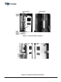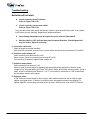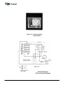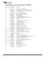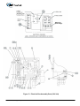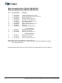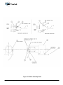
1
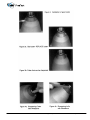
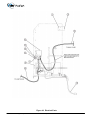
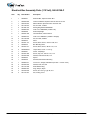
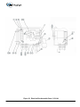
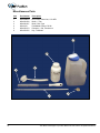
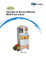
Operator & Service Manual
Multi-Fruit Juicer
March 2009
Operator & Service Manual
Multi-Fruit Juicer
Copyright © John Bean Technologies Corporation 2009
JBT FoodTech
400 Fairway Avenue
Lakeland, FL 33801
(863) 683-5411
Manual No. 060-00203 – March 2009
2
John Bean Technologies Corporation Multi-Fruit Juicer Service & Operational Manual
Safety Information····················································································· 4
Safety Instructions ···················································································· 5
General Information ·················································································· 7
Operating Instructions············································································ 10
Cleaning Instructions ············································································· 12
Maintenance ···························································································· 17
Periodic Inspection ················································································· 20
Troubleshooting ······················································································ 26
Rebuilding ································································································ 32
Kit Parts Listing ······················································································· 48
Juicing Components Listing ·································································· 50
Hopper Parts Listing ··············································································· 52
Drive Parts Listing ·················································································· 54
Upper Drive Parts Listing ······································································· 56
Upper Rod End Parts Listing ································································· 57
Orifice Drive Parts Listing ······································································ 58
Orifice Rod End Parts Listing ································································ 59
Frame & Stand Parts Listing ·································································· 60
Cover ABS Parts Listing········································································· 62
Splash Shield Parts Listing ···································································· 64
Decals, Warning Label Listing ······························································· 65
Cover SS Parts Listing ··········································································· 66
Electrical Parts Listing ··········································································· 68
Electrical Box 115V Parts Listing ·························································· 70
Electrical Box 220V Parts Listing ·························································· 72
Motor Assembly Parts Listing ······························································· 74
Miscellaneous Parts ·············································································· 76
John Bean Technologies Corporation Multi-Fruit Juicer Service & Operational Manual
3
Important Safety Information
You can help prevent personal injury and/or property damage.
Please read this manual carefully before operating the JBT FoodTech Extractor.
DO NOT attempt any operation until you understand exactly how the machine
functions.
If uncertainty remains after studying this manual, please contact:
John Bean Technologies Corporation
JBT FoodTech
400 Fairway Avenue
Lakeland, FL 33801
(863) 683-5411
or
The local JBT FoodTech service representative in your country.
We're here to help. With proper handling, the JBT FoodTech Juice Extractor will
provide safe, efficient and convenient service for years to come.
4
John Bean Technologies Corporation Multi-Fruit Juicer Service & Operational Manual
Safety Labels
The safety labels shown below appear on the Juice Extractor. They provide essential instructions
on how to avoid possible hazards.
Please, for your safety:
FOLLOW THOSE INSTRUCTIONS AT ALL TIMES.
Should the Juicer safety labels become damaged or unreadable, contact JBT FoodTech for
replacement labels.
Safety Instructions
Carefully review the following safety instructions.
Make them a habit when using the JBT FoodTech Juice Extractor.
1. If extractor continues to run when any access cover is open, interlock switch is defective.
Turn Juicer off immediately. Call for service.
2. Prevent unauthorized access to Extractor by locking all covers with supplied key.
3. Prevent unauthorized operation of Extractor by placing electrical plug inside cart door.
4. NEVER attempt to make any safety device inoperative.
5. NEVER operate or perform maintenance or repair work on Extractor when taking any kind of
drug or sedative, when under the influence of alcohol, or when fatigued.
6. ALWAYS check adjustment of all nuts, bolts, and screws after installation, repair, or periodic
maintenance.
John Bean Technologies Corporation Multi-Fruit Juicer Service & Operational Manual
5
Technical Specifications
Fruit size: 2 1/2" to 3 3/4" diameter (6.5 cm to 9.5 cm)
Oranges — FL: ·········································· 125 to 50 count
Oranges — CA: ········································· 138 to 48 count
Grapefruit — FL: ······································ 56 to 48 count
Hopper capacity: ······································· 40 Ib. (1 carton) (18 kg)
Reservoir capacity: ··································· 3 1/2 gal. (1 carton) (13.2 liters)
Waste container capacity: ························· 40 Ib. of peel (2 cartons) (18 kg)
Speed: ······················································ 20 fruit/minute
(20 to 60 gallons/hour)
(75 to 225 liters/hour)
Electrical Specifications
115V 60 HZ Single Phase 20 AMP Service
12 GA. wire — up to 100 ft. from main breaker panel
or
10 GA. wire — up to 200 ft. from main breaker panel
220 VAC 50 HZ Single Phase 16 AMP Service
Shipping Specifications
Machine With Stand:
Height:
67"
Width:
27"
Depth:
32"
Weight: 535 Ibs
(170 cm)
(69 cm)
(81 cm)
(243 kg)
Patents
U.S. Patents - #4905586 and #4922814
& Patents Pending
6
John Bean Technologies Corporation Multi-Fruit Juicer Service & Operational Manual
General Information
The JBT FoodTech Juice Extractor is designed to provide years of dependable service. It
uses a unique patented design to extract every available amount of juice from the fruit with
the least amount of peel oil. The peel is completely separated from the juice and juice sacs
before being compressed and strained.
The machine will juice all types of citrus — oranges, grapefruit, lemons, limes, tangerines,
etc. — without changing or adjusting parts. In fact, different varieties and sizes of fruit can
be juiced to create various fruit juice blends.
Clean-up is simple, requiring disassembly of only five parts. All waste material — peel,
membranes, and seeds — is collected in a disposable garbage bag for easy removal and
disposal.
The Juice Extractor is solidly built using heavy duty components in all assemblies, including
the drive. It is simple to operate and uses a minimal number of parts.
ALWAYS follow cleaning and maintenance schedules in this manual to prevent equipment
damage.
For a quick introduction to the JBT FoodTech Juice Extractor, please review the diagram
on the next page.
John Bean Technologies Corporation Multi-Fruit Juicer Service & Operational Manual
7
Single Feed Hole
¼ turn lock
Back Cover
Hopper Cover
Hopper
Drive Cover
On-Off Switch
¼ turn lock
Juice
Components
Cover
Stirrer Handle
Juice Nozzle
Juice Reservoir
Juice Reservoir
Valve
Cart Cover
¼ turn lock
Cart Door
Figure 1a. JBT FoodTech Juicer Extractor
8
John Bean Technologies Corporation Multi-Fruit Juicer Service & Operational Manual
Figure 1b. Juicing Components Assembly
Figure 1c. Inside Cart Door
John Bean Technologies Corporation Multi-Fruit Juicer Service & Operational Manual
9
Operating Instructions
Equipment Check
Before plugging the JBT FoodTech Juice Extractor into an electrical outlet, the
following steps must be performed:
1.
Locate the Citrus Juicer on a level surface.
This will prevent fruit feed problems.
2.
Lock both rear casters.
To lock, push down on caster with foot. To unlock, push again with foot.
3.
Check waste container.
Open cart door to verify that waste container is in place. A plastic bag may be
attached to the hooks above the waste container (recommend the "Hefty Cinch
Sak®", 30 gallon capacity or equivalent).
4.
Check juicing components.
a. Twist and pull juice nozzle off.
b. Use key to unlock juicing components cover. Open cover and check that juicing
components are installed and securely fastened. See Figure 1b, page 9.
5.
Close and lock all access covers.
There are 4 separate access covers: hopper cover, juicing components cover, cart
door (cover) and back cover.
NEVER operate extractor unless all covers are in place.
6.
Replace juice nozzle.
7.
Make sure juice reservoir is firmly in place.
8.
Make sure juice reservoir valve is in closed position.
9.
Check the hopper for foreign objects.
Remove any foreign objects found in the hopper.
10. Make sure floor area around extractor is clean and free of obstructions and water.
When water is necessary, wear appropriate non-slip footwear.
10
John Bean Technologies Corporation Multi-Fruit Juicer Service & Operational Manual
Operating Instructions
Juicing
CAUTION: DO NOT RUN EXTRACTOR WITHOUT FRUIT FOR MORE THAN ONE
MINUTE. EQUIPMENT DAMAGE WILL RESULT.
1.
Turn on Extractor.
Push the "ON-OFF" button to "ON" position.
2.
Fruit may be fed into Extractor one at a time (Single Feed) or in bulk.
a. Single Feed
Remove hopper single feed hole cover.
Twist and pull cover to remove.
Drop fruit individually down single-feed chute through hole in hopper cover.
DO NOT overload chute or fruit will accidentally be double fed.
b. Bulk Feed
Unlock and open the hopper cover.
Dump up to one carton (40 Ibs.) of fruit into the hopper.
Fruit may be divided between the carton and carton lid for ease of lifting.
3.
DO NOT use the single-feed chute when hopper is full.
Fruit will accidentally be double fed.
4.
Turn-off Extractor.
Push the "ON-OFF" Switch to the "OFF" position.
5.
Stir juice.
Use stirrer handle to stir juice in reservoir before filling containers.
6.
Fill containers.
Place container under juice reservoir valve. Open valve by turning lever until
container is full.
7.
Clean Extractor.
If finished juicing, clean Extractor as soon as possible.
(See next page for cleaning instructions.)
John Bean Technologies Corporation Multi-Fruit Juicer Service & Operational Manual
11
Cleaning Instructions
ALWAYS follow cleaning and maintenance schedules in this manual to prevent
equipment damage.
Clean Extractor as soon as possible for juicing. Use a soft towel or sponge to wipe
equipment parts. DO NOT use abrasive pads such as Scotch Brite®, steel wool, etc.
The recommended cleaner is "Pelican" brand Peralkalate. Peralkalate is a low-foaming
alkaline equipment cleaner. It is safe on aluminum, 100% water soluble and free rinsing.
Peralkalate has been especially formulated for cleaning food processing equipment and is
USDA accepted. Follow instructions on cleaner label for dilution.
12
1.
Turn-off Extractor with Juicing Component cups separated.
2.
DISCONNECT ELECTRICAL PLUG.
3.
Pull Extractor to clean-up area, if one is available.
4.
Brush all loose peel into waste container or bag.
5.
Empty and rinse waste container.
John Bean Technologies Corporation Multi-Fruit Juicer Service & Operational Manual
Cleaning Instructions
6.
Remove juicing components.
a. Cups should be separated. (Extractor should have been turned off with cups in
the separated position.)
b. Grasp upper cup and pull out pin just above it. Place upper cup in waste
container.
CAUTION: DO NOT PLACE HANDS OR FINGERS BETWEEN CUPS.
c.
Remove splatter shield by sliding upwards off mounting screws.
d.
Remove lower cup by removing spanner nuts on either side of lower cup. (A
spanner wrench is provided to loosen/tighten spanner nuts).
Place lower cup in waste container.
CAUTION: CUTTER AND KNIVES ARE SHARP.
e.
Install red protective cap on cutter.
(Red protective cap is provided.)
f.
Grasp juice manifold and orifice tube firmly. Remove entire juicing components
assembly.
g.
Grasp orifice tube and pull out of strainer tube.
h.
Remove strainer tube from inside juice manifold by turning tube counterclockwise and sliding out. (A spanner wrench is provided to loosen/tighten
strainer tube.)
Place juicing components into waste container.
John Bean Technologies Corporation Multi-Fruit Juicer Service & Operational Manual
13
Figure 2. Juicing Components
14
John Bean Technologies Corporation Multi-Fruit Juicer Service & Operational Manual
Prepare cleaning solution.
7.
"Pelican" brand Peralkalate is recommended, see page 12.
Read the product label. Follow the manufacturer's mixing directions and safety
precautions.
8.
Immerse all components in cleaning solution.
Use the blunt end of plastic rod provided to displace any fruit material lodged in the
bore of the orifice tube.
Use pointed end of plastic rod to displace any fruit material lodged in cup fingers.
9.
Scrub components.
Use a brush, towel, or sponge. DO NOT use abrasive pads such as Scotch Brite",
steel wool, etc. Thoroughly rinse with clean water, then thoroughly rinse with sanitizer
solution. Follow the manufacturer's mixing directions and safety precautions.
10. For best results, soak strainer tube overnight.
After soaking overnight, rinse the strainer tube thoroughly before using. Check that all
strainer tube holes are clean. Clean strainer tube with a hard spray from a hose
while moving orifice tube back and forth in strainer tube. Rinse thoroughly with
sanitizer solution. Allow to air dry.
11. If possible, hose down juicing area and cover.
If location prohibits using a hose to clean juicing area and cover, ensure waste
container is in place. Wash down the exposed juicing area and cover with a sponge
or spray applicator using the recommended cleaning solution. Cover may be rinsed in
place or removed by lifting it off the hinges. Allow to stand for two minutes before
rinsing thoroughly with water.
12. Re-assemble juicing components.
Start by re-assembling strainer tube into juice manifold. Tighten with spanner
wrench. Insert orifice tube into bottom of strainer tube. Mount juice manifold
assembly onto locating pins with orifice tube notch engaging lower drive. Tighten
spanner screw with spanner wrench. Remove red protective cap from cutter. Install
lower cup and tighten spanner nuts with spanner wrench. Install upper cup by
slipping pin into stem hole. Install splatter shield.
Refer to Figure 2, page 14.
John Bean Technologies Corporation Multi-Fruit Juicer Service & Operational Manual
15
13. As necessary, hose down drive area.
Remove back cover (Turn lock at top 1/4 counter-clockwise.
Pull cover out by using finger hole left of lock, then lift and pull cover using finger hole
on bottom. DO NOT loosen any screws.) Open hopper cover. Open cart door (cover).
Hose down all exposed areas. Extractor is water-resistant. DO NOT use any cleanser
in drive area.
14. Remove wax build-up as needed.
Cups, hopper and other parts may acquire a build-up of wax over time.
a. Soak cups for five minutes in an ammonia cleaning solution.
Rinse thoroughly with sanitizer solution.
b. Wipe hopper and other parts with a cloth soaked in ammonia cleaning
solution.
15. Remove orange discoloration as needed.
Equipment may exhibit some build-up or orange coloration over time. Peralkalate
Solution should remove this. Wipe with a cloth soaked in any pine based cleaner
(such as Pine Power or Pine Spic & Span') to remove discoloration from plastic
covers.
Rinse thoroughly with sanitizer solution.
16. Clean Tomlinson faucet.
Daily cleaning is crucial to the performance, maintenance and sanitation of the
faucet.
Take apart handle assembly and flush with clean water, then sanitize.
16
John Bean Technologies Corporation Multi-Fruit Juicer Service & Operational Manual
Maintenance
Before performing any maintenance,
DISCONNECT ELECTRICAL PLUG.
After every juice run:
1.
Check cutter and knives for sharpness.
Refer to Figure 3 to determine condition of cutter.
If dull, sharpen with a whetstone provided.
Refer to Figure 4a to sharpen cutter.
If cutter is severely damaged or rolled over, replace cutter.
a.
Cutter removal:
Disassemble juicing components per Figure 1b, page 9. Loosen set screw under front knife
(make sure screw is backed out far enough to clear cutter). Cutter should lift out, if not, tap
the cutter lightly from inside the juice manifold with a 1-1/4" dia rod (hammer handle).
CAUTION: CUTTER AND KNIVES ARE SHARP.
Install red protective cap provided onto cutter. After red protective cap is installed, remove
cutter. Handle cutter with care to avoid direct contact with sharp edge.
b.
Cutter installation:
Align arrows on cutter and juice manifold to seat cutter. Make sure cutter is fully seated.
Tighten set screw.
(DO NOT over-tighten.)
John Bean Technologies Corporation Multi-Fruit Juicer Service & Operational Manual
17
18
John Bean Technologies Corporation Multi-Fruit Juicer Service & Operational Manual
Maintenance
2.
Check orifice tube for damage.
Refer to Figure 5
Replace tube when:
a. Chunks are missing from top end.
b. Score marks 1/32" or deeper appear along the length of the tube.
Figure 5. Severely Damaged Orifice Tube
3.
Check for loose or missing nuts and bolts.
a. Tighten or replace nuts and bolts as necessary.
b. DO NOT exceed torque ranges specified in Service Manual
c. ALWAYS use JBT FoodTech recommended spare parts.
John Bean Technologies Corporation Multi-Fruit Juicer Service & Operational Manual
19
Periodic Inspection
Perform the following steps after every 3 - 4 months.
1.
Test all access cover interlock switches.
Extractor should stop automatically when any access cover is opened. Individually open and
close the four access covers (hopper, juice components, cart and back). If extractor continues
to run when any access cover is opened, the interlock switch is defective.
Stop the extractor and replace immediately.
See Trouble Shooting Section.
2.
Check all fasteners for tightness.
Check especially on the Sprockets, Crank Arms, Fruit Lift, and Hopper.
3.
Check chain for tightness.
Refer to Figure 6.
Chain should have 1/4 inch maximum slack on top side. To adjust, (see Figure 7) loosen the four
bolts holding the gearbox base to frame, move motor/ gearbox to the correct adjustment. (If
necessary, use a small board to pry between frame and motor.)
CAUTION : DO NOT OVER TIGHTEN CHAIN.
4.
20
Check chain and sprockets for rust.
If rust appears, coat chain and sprockets with a small amount of grease.
John Bean Technologies Corporation Multi-Fruit Juicer Service & Operational Manual
Figure 6. Checking Chain Slack
Figure 7. Loosening Bolts on Base of
Motor, and Prying Motor
John Bean Technologies Corporation Multi-Fruit Juicer Service & Operational Manual
21
Periodic Inspection
5.
Check oil level in gearbox.
Refer To Figure 8.
If Extractor has been laid on its side for any reason (i.e., during shipping), or if there is any evidence of
oil leak, check gearbox for proper oil level. Remove back cover. Oil level plug is located on the left side
of gearbox. Filler plug is located on the top of the gearbox.
Use S.A.E. 40W oil only.
6.
Check hopper bump button.
Refer to Figure 9b.
Replace bump button if it has worn to less than 1/8" high. To locate hopper bump button, remove
hopper.
a.
Hopper removal:
Fruit lift (upper cup drive) must be in down position. Remove two spanner screws using
spanner wrench. Remove hopper. If hopper does not lift out, see Troubleshooting, page 26,
item 'a', to remove electrical switch cover.
b.
Hopper installation:
DO NOT over tighten spanner screws. Hopper is designed to be loose. Hopper must be free
to "bump" during each cycle to prevent fruit bridging.
22
John Bean Technologies Corporation Multi-Fruit Juicer Service & Operational Manual
Figure 8. Checking Oil Level in Gearbox
Figure 9a. Hopper Removal
Figure 9b. Bump Button
Installation
John Bean Technologies Corporation Multi-Fruit Juicer Service & Operational Manual
23
Periodic Inspection
7.
Check alignment of fruit lift.
Refer to Figure 10.
Fruit lift agitator dividers must align with the middle of slots in bottom of hopper.
a.
Fruit lift adjustment:
Refer to Figure 11.
Loosen the two cap screws attaching the fruit lift to upper
cup drive arm. Adjust fruit lift.
Tighten cap screws.
b.
Fruit lift repair:
If fruit lift is damaged (bent, but not broken), it can be removed and straightened. Remove
hopper before fruit lift. Straighten fruit lift.
Reinstall fruit lift with Loctite #242 on cap screws.
8.
Check to make sure two plastic bearing buttons have been installed on bottom face of fruit
lift.
Refer to Figure 12.
Figure 10. Fruit Lift Alignment
24
John Bean Technologies Corporation Multi-Fruit Juicer Service & Operational Manual
Figure 11. Fruit Lift Bolts
Figure 12. Fruit Lift Plastic Bearings
John Bean Technologies Corporation Multi-Fruit Juicer Service & Operational Manual
25
Troubleshooting
Extractor will not start.
1.
2.
3.
4.
Extractor is not plugged into electrical outlet.
Building circuit breaker has tripped.
All covers are not completely closed
Defective interlock switch.
Machines built before 1997 have five interlock switches
Refer to Figure 13.
1 - Hopper cover
1 - Back cover
1 - Cart door (cover)
*1 - Juicing Component cover
1 - High Level Switch
Machines built in 1997 and later have two Schmersal Switches.
Refer to Figure 15c.
a.
Remove the large cover protecting electrical box and motor.
Refer to Figure 14.
Loosen three screws in juicing area. Remove three screws
on the right side.
Remove electrical box cover with on-off switch.
*Two on Machines without High Level Switch
26
John Bean Technologies Corporation Multi-Fruit Juicer Service & Operational Manual
Figure 13. Interlock Switch Locations
Figure 14. Removal of Switch Cover Panel
John Bean Technologies Corporation Multi-Fruit Juicer Service & Operational Manual
27
Troubleshooting
Extractor will not start.
b.
Check continuity thru all switches.
Refer to Figure 15b & 15c.
c.
Check continuity across each switch.
Refer to Figure 15b & 15c.
Using a meter, check each switch individually. Check by opening and closing each cover related
to the switch you are checking. Replace any defective switches.
d.
Some linkage adjustment may be required on juice reservoir float switch.
e.
Machines built in 1997 and later have two Schmersal Switches. Check alignment of
key and switch. Adjust if necessary.
5. Loose wire connection.
Check all spade and screw terminals.
With wires still connected, remove cover to motor starter and check for loose wires on D1 and D2.
6. Defective under voltage coil.
Check continuity from terminals D1 to D2.
Using a meter, check for continuity from terminal D1 to D2.
If no continuity is detected, replace under voltage coil.
7. Defective motor starter.
Check continuity from terminal 1 to 6.
Remove cover on motor starter by grasping both sides and pulling straight out. Remove under
voltage coil by lifting and pulling out. Push "ON" button. Button should stay in down position. Using a
meter, check for continuity from terminal '1 ' to '6.' If no continuity is detected, or "ON" button does
not stay down, replace motor starter.
8. Defective motor.
If "ON" button on starter stayed in when trying to start machine and motor did not start or rotate,
replace entire gear motor. If there is a humming noise, the capacitor needs to be replaced. To
replace capacitor, remove long cylindrical cover on motor. Reseal motor cover with RTV Silicone.
28
John Bean Technologies Corporation Multi-Fruit Juicer Service & Operational Manual
Figure 15a. Sprecher Schuh
Electrical Box
John Bean Technologies Corporation Multi-Fruit Juicer Service & Operational Manual
29
See Page 47 for 220V Diagrams
30
John Bean Technologies Corporation Multi-Fruit Juicer Service & Operational Manual
Troubleshooting
Machine starts, but shuts off.
1.
Building circuit breaker is not rated for 20 Amps.
2.
Extension cord or wiring is too long.
Shorten extension cord or use heavier gauge wire.
(See page 6 "Electrical Specifications")
3.
All covers not completely closed (including cart).
Extractor may be flexing when squeezing fruit, causing switch to open. Make sure all latches
are completely locked
4.
Amperage setting on motor starter on machine set too low.
See page 26, item 'a', under "Extractor will not start" for removing covers. Dial next to "OFF"
button should be set at 14.
CAUTION: IF SETTING IS TOO HIGH, MOTOR WILL BURN UP.
Extractor stalls trying to squeeze a fruit.
1.
Fruit has part of stem on it.
Turn off Extractor. Remove fruit from Extractor and restart.
2.
Peel is too thick.
Turn off Extractor. Remove fruit from Extractor and restart.
3.
Cutter is damaged.
Sharpen or replace cutter as specified on under maintenance.
CAUTION: CUTTER AND KNIVES ARE SHARP.
Install red protective cap onto cutter.
After red protective cap is installed, remove cutter. Handle cutter with care to avoid
direct contact with sharp edge.
Extractor runs with covers open or off.
1.
Defective interlock switch. Replace immediately.
See page 26, item 'a', under "Extractor will not start" for removing covers.
Extractor emits a "squealing" sound during operation.
1.
Lubricate grease fittings on machine.
If noise continues, rod end or bearing is defective, see Rebuilding section to replace bearings.
Scraping noise coming from hopper area.
1.
Fruit lift mechanism is dragging on hopper.
See page 24, item 7 under “periodic inspection”.
John Bean Technologies Corporation Multi-Fruit Juicer Service & Operational Manual
31
Rebuilding
It is best to replace all bearings at the same time.
Step-by-Step instructions for replacing all bearings and rod ends.
1.
Remove all juicing components
2.
Lift juicing component cover off its hinges.
Refer to Figure 1.
Remove back cover (1/4 turn lock at top, pull cover out by using finger hole to the left of the lock,
then lift and pull using finger hole of bottom. DO NOT loosen any screws). Remove drive cover,
one screw on top, and two on the side.
(DO NOT loosen lower two screws).
3.
Remove upper and lower drive splash plates in juicing area.
Refer to Figure 16.
Use knife to cut away Silicone from plastic splash plates and drive arms. If necessary, use hand
crank adapter on motor sprocket with 1/2" drive ratchet to rotate machine into position to pull off
splash plates.
Refer to Figure 17 and Figure 36, item 12.
32
John Bean Technologies Corporation Multi-Fruit Juicer Service & Operational Manual
Figure 16. Front View of Juicer
Figure 17. Back View of Juicer
John Bean Technologies Corporation Multi-Fruit Juicer Service & Operational Manual
33
Rebuilding
4.
From 3" inch square access hole on side of machine, use a 5/16" Allen wrench to
loosen socket head cap screw on crank arm for upper cup drive .
(Use hand crank adapter to rotate as necessary).
Use a 3/16" Allen wrench to loosen set screw on keyway. Back screws out at least 1/4" to
clear flats on shafts.
Refer to Figure 18.
From the back repeat above steps on crank arm for lower drive.
Refer to Figure 19.
5.
Rotate drive so upper cup drive is in the down position.
Remove chain, spring clip type master link.
Be careful- drive arms may move as chain is removed.
6.
Remove sprockets with shafts still connected.
Pull or pry on large diameter upper drive sprocket, repeat for lower drive sprocket.
Refer to Figure 20.
Figure 18. Using Allen Wrench to Loosen Upper Cup Crank Arm.
34
John Bean Technologies Corporation Multi-Fruit Juicer Service & Operational Manual
Figure 19. Loosening Lower Crank Arm
Figure 20. Sprockets with Shaft being Removed
John Bean Technologies Corporation Multi-Fruit Juicer Service & Operational Manual
35
Rebuilding
7.
Remove linear shafts.
With a 3/16" Allen wrench, loosen set screws at top and bottom of all three shafts. Back
screws out at least 1/4" to clear flats on shafts. If shafts are stuck, use bearing removal puller
with 3/8"-16 x 2" hex head cap screw to break free shafts.
Refer to Figure 21.
8.
Lift out upper and lower drive arms with linkages still attached.
9.
Disassemble rod end assemblies from drive and crank arms.
Note location and numbers of washers and spacers.
NOTE:
Screws and rod ends on both crank arms are left hand threads.
10. Disassemble rod ends from links.
Reassemble with new rod ends (Refer to Figures 22 and 23), using rod end adjustment bar
with the appropriate rod and tooling washer. Remember one end is a left-handed thread.
Wrenches required - 3/4", 7/8", and 15/16".
Figure 21. Removal of Linear Shafts with Puller
36
John Bean Technologies Corporation Multi-Fruit Juicer Service & Operational Manual
Figure 22. Assembly of 5/8" Rod Ends
Figure 23. Assembly of 1/2" Rod Ends
John Bean Technologies Corporation Multi-Fruit Juicer Service & Operational Manual
37
Rebuilding
11. Remove sleeve bearings from upper and lower drive arms.
Refer to Figures 24 and 25
Bearings can be pulled out using puller, 1" removal slug, and short threaded removal rod; or can
be driven or pressed out using driver. New bearings can be installed by compression (Figure 26)
by using installation pilot, installation washer and long threaded installation rod, or just use
installation pilot and press bearings into place. Light coat of Teflon® grease can be used on O.D.
of bearings.
Figure 24. Removing Bearings from Upper Drive Arm
38
John Bean Technologies Corporation Multi-Fruit Juicer Service & Operational Manual
Figure 25.
Removing Bearings from
Lower Drive Arm
Figure 26. Installation of Bearings into Drive Arms
John Bean Technologies Corporation Multi-Fruit Juicer Service & Operational Manual
39
Rebuilding
12. Reassemble rod end assemblies to drive arms, again making sure left hand threaded
ends are on the crank arms.
Refer to Figures 27 and 28.
Use Loctite #242 on all fasteners. Tighten to torques as shown. Make sure rod end lock
spacer is installed on rod end in upper drive arm. Make sure plastic bearing buttons are
installed on each side of lower drive arm.
Figure 27. Completed Assembly of Upper Cup Drive Arm
40
John Bean Technologies Corporation Multi-Fruit Juicer Service & Operational Manual
Figure 28. Completed Assembly of Lower Drive Arm
John Bean Technologies Corporation Multi-Fruit Juicer Service & Operational Manual
41
Rebuilding
13. Remove sleeve bearings from main frame.
Refer to Figures 29 and 30.
The outer upper drive shaft bearing can be removed using puller, 1-1/4" removal slug, and short
threaded removal rod.
The inner bearing can be removed the same way, or can be pressed out using driver. The lower
shaft bearing can be removed the same way except using 1" removal slug. New bearings can be
installed by compression (Figure 31) by using installation pilot, installation washer, and long
threaded installation rod. Light coat of Teflon grease can be used on O.D. of bearings to aid in
installation.
14. There are thrust washers next to each bearing on the main frame. Make sure the old
ones have been removed and new ones installed.
One side of thrust washer is plain metal. Silicone this side and glue them to the frames
(Typical 4 places).
DO NOT get silicone on surface of any bearing.
15. Before reassembling, check all shafts for excessive wear; replace as necessary.
Reassemble parts in the reverse order of removal. DO NOT forget to put keys back into crank
arms.
On both crank arms, be sure to tighten socket head cap screw first. And then the set screw.
Tighten fasteners to torques shown.
Lubricate all grease fittings if provided.
Figure 29. Removing Bearing from Lower Rotary Drive
42
John Bean Technologies Corporation Multi-Fruit Juicer Service & Operational Manual
Figure 30.
Removing Bearing from
Upper Rotary Drive
John Bean Technologies Corporation Multi-Fruit Juicer Service & Operational Manual
43
Rebuilding
16. Before installing chain, align timing marks as shown.
Refer to Figure 32.
This is critical to operation of the machine. Adjust chain as shown in Maintenance section.
17. To check to see if upper cup crank rod end link needs to be adjusted, install juice
manifold, upper and lower cup.
Refer to Figure 33.
Using hand crank adapter, gently rotate until upper cup drive is in the full down position. DO NOT
force it, if it appears to be binding, readjust rod end link (Figure 34). If it rotates freely past bottom
position, check for too much clearance. In the full down position remove pull pin from upper cup.
Cup should not drop down; if it does, readjust rod end link.
Cups should just meet - no clearance - no bind.
Figure 32. Alignment of Timing Marks
44
John Bean Technologies Corporation Multi-Fruit Juicer Service & Operational Manual
Figure 33. Checking for Cup Clearance
Figure 34. Adjusting Rod Link Ends
John Bean Technologies Corporation Multi-Fruit Juicer Service & Operational Manual
45
Rebuilding
18. Remove juicing components and install upper and lower drive splash plates.
Refer to Figure 35a and 35b.
Note that chamfer on top front edge of lower splash plate goes up and out. Put thin part to the top,
and flat backside against the wall. Also note that groove in upper drive splash plate goes down
and in. Seal with R.T.V. Silicone, allow to dry before running machine
Figure 35a. Applying Silicone to
Upper Splash Plate
Figure 35b. Applying Silicone to Lower Splash Plate
46
John Bean Technologies Corporation Multi-Fruit Juicer Service & Operational Manual
Machines built before 1997
Machines built in 1997 and later
John Bean Technologies Corporation Multi-Fruit Juicer Service & Operational Manual
47
Rebuild Tooling Kit & Spare Parts Kits
Item
Part Number
Description
1
2
3
4
5
6
7
8
9
10
11
12
13
14
15
16
17
18
19
20
060-00180-B
060-00181-B
060-00182-B
060-00183-B
060-00184-B
060-00185-B
060-00186-B
060-00187-B
060-00188-B
060-00189-B
060-00190-B
060-00191-B
004-350-648
004-350-571
004-110-063
004-815-100
00-4815-080
004-350-407
004-410-046
009-998-004
060-00202
Tool, Bearing Installation Pilot
Tool, Bearing Installation Washer
Tool, Bearing Puller
Tool, Bearing Removal Slug 1"
Tool, Bearing Removal Slug 1-1/4"
Tool, Bearing Removal Driver
Tool, Bearing Installation Rod
Tool, Bearing Removal Rod
Tool, Washer, Rod End, 1/2"
Tool, Washer, Rod End, 5/8"
Tool, Rod End Adjust Bar
Tool, Adapter, Hand Crank
Screw, Cap, Hex, 5/8-11 x 1-1/2", C/G
Screw, Cap, Hex, 1/2-13 x 1-1/2", Full Thread, C/G
Nut, Hex,1/2-13, Grade 8 Steel
Washer, Plain Narrow, 1/2", C/G
Washer, Plain Narrow, 3/8", C/G
Screw, Cap, Hex, 3/8-16 x 2", C/G
Screw, Set, Square Head, Dog Pt, 3/8-16 x 3/4"
Bit, Spanner Insert, #8, 1/4 Hex (Not Pictured)
Kit, Tool, CJ & MFJ (Includes above Items 1 - 20)
Other Multi-Fruit Juicer Kits
060-00201
060-00215
060-00200
Kit, Bearing Overhaul
Kit, Complete Overhaul
Kit, Spare Parts
Cleaning Components & Other Parts
060-00084
009-080-326
060-00131
009-710-031
003-460-053
003-460-057
003-015-905
48
Rod, Orifice Clean Out
Brush, 1-1/16" x 8"
Peralkalate Cleaner 750 M
Stone, Sharpening
Lubricant, W/ Teflon, 3 Oz Tube
Lubricant, W/ Teflon, 14 Oz Can
Silicone, White, 3 Oz Tube
John Bean Technologies Corporation Multi-Fruit Juicer Service & Operational Manual
Figure 36. Rebuild Kit
John Bean Technologies Corporation Multi-Fruit Juicer Service & Operational Manual
49
Juicing Parts, 060-00099-F
Item
1
2
3
4
5
6
6
7
7
8
9
10
11
12
13
14
15
16
17
18
18a
19
20
20a
20b
21
22
26
30
31
32
33
34
50
Qty Part Number
Description
1
2
2
1
3
1
1
1
1
1
1
1
2
2
1
1
1
1
2
1
1
2
1
1
1
1
1
1
1
1
2
2
2
060-00103
004-352-410
004-816-080
060-00056
060-00051
060-00043
060-00043-01
060-00118
060-01001
060-00038
060-00028
060-00004
060-00098
060-00109
060-00225
004-406-003
060-00108
007-486-119
004-352-398
060-00022
060-01059
060-00068
060-00086
060-00208
060-00230
060-00055
060-00008-1
060-00077
009-092-018
060-00121
060-00192
004-100-018
004-806-070
Drive Assembly (Details See Pages-54-55)
Screw, Cap, Hex, 3/8-16 x 2-1/4", S.S.
Washer, Plain Narrow, 3/8",S.S.
U.C. Drive Cover Plate
Spanner Screw
Hopper Assembly, ABS
Hopper Assembly, SS
Cover Assembly, ABS (Details See Pages 62-63)
Cover Assembly, Stainless Steel (Details See Pages 66-67)
Lift, Fruit, FDA Material
Guide, Fruit, FDA Grade
Cup, Lower
Spanner Nut
Stud, Cup, Lower
Cutter With Screw
Screw, Mach, Round, 4-40 x 3/16,S.S.
Manifold, Juice
O-Ring, Nozzle, 1 x 1-1/8 x 1/16
Screw, Cap, Hex, 3/8-16 x 1-1/4", S.S.
Nozzle, Straight , Plastic
Nozzle, SS, 90° Bend, Jamba
Bearing, Fruit Lift
Tube, Strainer, .033
Tube, Strainer, .040
Tube, Strainer ,.055
Plate, Orifice Drive, FDA Grade
Tube, Orifice
Tool, Wrench
(Not Shown)
Cap, Cover for Cutter
(Not Shown)
Warning Label, Shear, Hopper
Pin, Manifold Locator
Nut, Acorn, 3/8-16, SS
Washer, Lock, 3/8", SS
1
2
1
1
060-00088
060-01069
060-01066
060-01067
Parts for Small Fruit
Restrictor, Fruit Hole, Small Fruit
Guide Block, Small Fruit
Restrictor, Hopper Side, Small Fruit
Restrictor, Juicing Side, Small Fruit
(Not Shown)
(Not Shown)
(Not Shown)
John Bean Technologies Corporation Multi-Fruit Juicer Service & Operational Manual
Figure 37a. Juicing Parts
•
SMALL FRUIT INSERT (PART #060-00088-B)
PREVENTS DOUBLE FEEDING OF SMALL
FRUIT DOWN TO 2 ¼ " DIAMETER.
•
SLIPS OVER UPPER HALF OF HOLE FLANGE
IN FRUIT LIFT
•
REMOVE WHEN RUNNING LARGER FRUIT
•
USING SPANNER WRENCH IN HOLES WILL
AID IN INSTALLATION & REMOVAL
LOWER CUP, REF.
UPPER CUP NOT SHOWN
Figure 37b. Small Fruit Adapter
John Bean Technologies Corporation Multi-Fruit Juicer Service & Operational Manual
51
Hopper Assembly Parts, 060-00043-F
Item
1
2
3
4
5
6
Qty Part Number
1
1
1
7
1
2
060-00042
060-00019
060-00018
004-260-018
060-00089
004-260-015
Description
Hopper
Trough
Divider
Rivet, Blind, 3/16 x 5/16 Grip (7/16 lg), S.S.
Button, Hopper Bump
Rivet, Blind, 3/16 x 1/4 Grip (13/32 lg), S.S.
Figure 38. Hopper Assembly Parts
52
John Bean Technologies Corporation Multi-Fruit Juicer Service & Operational Manual
John Bean Technologies Corporation Multi-Fruit Juicer Service & Operational Manual
53
Drive Parts, 060-00103-F
Item
1
2
3
4
5
6
7
8
9
10
11
12
13
14
15
16
17
18
19
20
21
22
23
24
25
54
Qty Part Number
1
1
1
1
4
4
4
1
2
1
1
3
2
1
2
1
2
11
1
1
1
1
1
2
005-220-145
005-221-291
060-00034
005-806-227
004-352-404
004-806-070
004-816-080
060-00117
060-00064
060-00116
060-00010
004-355-116
005-098-113
060-00062
005-576-249
060-00065
005-098-112
005-576-242
004-405-131
060-00061
005-576-061
005-576-246
060-00115
060-00063
004-541-111
Description
Chain, #60 x 60-3/4" Lg (81 Links)
Link, Connecting For #60
Electrical Assembly (Details See Pages 68-69)
Sprocket, 60B14, Set Screw (for motor)
Screw, Cap, Hex, 3/8-16 x 1-3/4"
Washer, Lock Reg, 3/8", S.S.
Washer, Plain Narrow, 3/8", S.S.
Frame & Stand Assembly (Details See Pages 60-61)
Shaft, Linear, Upper
Upper Drive Arm Assembly (Details See Page 56)
U.C. Drive Arm Sprocket, Upper Cup
Screw, Cap, Socket, 3/8-16 x 2"
Washer, Thrust, 1-1/4"
Shaft, Rotary Drive, Upper
Key, Sq, 1/4" x 1-1/2", S.S.
Sprocket, Drive, Orifice
Washer, Thrust, 1"
Key, Sq, 1/4" x 1", S.S.
Screw, Cap, Socket, 3/8-16 x 3/4"
Shaft , Rotary Drive, Lower
Key, Sq, 1/4" x 3/4", S.S.
Key, Sq, 1/4" x 1-1/4", S.S.
Orifice Drive Arm Assembly (Details See Page 58)
Shaft, Linear Orifice Drive
Screw, Set, Socket, 5/16-18 x 3/4", S.S. (for Motor Sprocket)
John Bean Technologies Corporation Multi-Fruit Juicer Service & Operational Manual
Figure 39. Drive Parts
John Bean Technologies Corporation Multi-Fruit Juicer Service & Operational Manual
55
Upper Drive Arm Assembly Parts, 060-00116-C
Item
1
1a
1b
2
3
4
5
6
7
8
9
Qty Part Number
1
2
4
1
1
1
1
1
1
4
1
060-00030
007-120-205
005-098-731
004-226-039
060-00027
004-352-661
060-00057
060-00114
060-00078
004-816-120
060-00009
Description
Arm, Upper Drive (this part includes items 1a & 1b)
Fitting, Grease, 1/4"-28, 45°
Bearing, 1" x 1"
Pin, Faspin, 3/8 x 1-5/8"
Cup, Upper
Screw, Cap, Hex, 5/8-11 x 2-1/2"
Lock, Rod End
Rod End Assembly, Upper Cup Drive (Details See Page 57)
Screw, Upper Cup Crank, LH
Washer, Plain Narrow, 5/8
Crank, Upper Cup Drive
Figure 40. Upper Drive Arm Assembly Parts
56
John Bean Technologies Corporation Multi-Fruit Juicer Service & Operational Manual
Rod End Assembly, Upper Cup Drive, Parts 060-00114-B
Item
1
2
3
4
5
Qty Part Number
1
1
1
1
1
005-098-729
004-116-046
060-00060
004-116-047
005-098-730
Description
Rod End, RH, 5/8",
Nut, Jam Hex, 5/8-18, S.S.
Linkage, Cup Drive
Nut, Jam Hex LH, 5/8-18, S.S.
Rod End, LH, 5/8"
Figure 41. Rod End Assembly, Upper Cup Drive
John Bean Technologies Corporation Multi-Fruit Juicer Service & Operational Manual
57
Orifice Drive Arm Assembly Parts, 060-00115-C
Item
1
2
3
4
5
6
6a
6b
7
Qty Part Number
1
2
1
1
1
1
1
2
2
060-00058
004-816-100
004-352-572
060-00113
004-352-571
060-00011
007-120-205
005-098-731
060-00068
Description
Orifice Crank Arm
Washer, Plain Narrow, 1/2, S.S.
Screw, Cap, Hex , LH
Rod End Assembly, Orifice Drive (Details See page 59)
Screw, Cap, Hex, 1/2-13 x 1-1/2"
Arm ,Orifice Tube Drive (this part includes items 6a & 6b)
Fitting, Grease, 1/4"-28, 45°
Bearing, 1" x 1"
Bearing, Fruit Lift
Figure 42. Orifice Drive Arm Assembly Parts
58
John Bean Technologies Corporation Multi-Fruit Juicer Service & Operational Manual
Rod End Assembly, Orifice Drive, Parts, 060-00113-B
Item
1
2
3
4
5
Qty Part Number
1
1
1
1
1
005-098-727
004-116-037
060-00059
004-116-038
005-098-728
Description
Rod End, Male, RH
Nut, Jam Hex, 1/2-20
Linkage, Orifice Drive
Nut, Jam Hex LH, 1/2-20
Rod End, Male LH, 1/2"
Figure 43. Rod End Assembly, Orifice Drive, Parts
John Bean Technologies Corporation Multi-Fruit Juicer Service & Operational Manual
59
Frame & Stand Assembly Parts, 060-00117-D
60
Item
Qty Part Number
Description
1
1a
1b
1c
2
3
5
6
7
12
13
14
15
16
1
2
2
2
1
2
5
4
4
2
1
16
18
22
Frame (The frame contains items 1a, 1b & 1c)
Fitting, Grease, 1/4"-28, Straight
(Not Shown)
Bearing, 1" x 1"
(Not Shown)
Bearing,1-1/4" x 1-1/4"
(Not Shown)
Stand
Caster, Swivel, 4"
Screw, Cap, Hex, 3/8-16 x 7/8"
Nut, Hex, #10-24, S.S.
Hook
Caster, Rigid, 4"
Locator, Waste Bin
Nut, Hex, 5/16-18, S.S.
Washer, Plain Narrow, 5/16, S.S.
Screw, Cap, Hex, 5/16-18 x 3/4"
060-00101
007-120-203
005-098-731
005-098-732
060-00048
009-080-526
004-352-392
004-111-022
004-461-025
009-080-527
060-00079
004-111-040
004-816-070
004-352-315
John Bean Technologies Corporation Multi-Fruit Juicer Service & Operational Manual
Figure 44. Frame & Stand Assembly Parts
John Bean Technologies Corporation Multi-Fruit Juicer Service & Operational Manual
61
Cover Assembly Parts, ABS, 060-00118-F
Item
1
2
Description
Cover, Drive, UL #R597016
Shield, Splatter, Assembly, 90° Bend (Details See Page 64)
Shield, Splatter, Curved (Obsolete-Old Style)
3
1
Cover, Juice Components, UL #R597016
4
1
Clip, Latch
5
24
Screw, Mach Truss, Nylok, #10-24 x 3/8" Phillips, S.S.
6
1
Plug, Hopper Hole, UL #R597016
7
2
Hinge, Cover, Front, Male
8
4
Washer, Plain Narrow 1/4", S.S.
9
1
Reservoir Lid, FDA Material
10
1
Stirrer, Reservoir
11
1
Reservoir, Juice, FDA Material
12
1
Faucet-Tomlinson
13
14
Screw, Mach Truss, #10-24 x 5/8" Phillips, S.S.
14
1
Cover, Door Stand, UL #R597016
15
1
Cover, Main Stand, UL #R597016
16
2
Pin, Reservoir Holder
17
1
Cover, Hopper, UL #R597016
18
1
Cover, Back, UL #R597016
19
1
Cover, Switch, UL #R597016
20
1
Spacer, Switch Cover
21
1
Name Plate
22
8
Rivet Blind, Pop,1/8 Dia. x 1/4 Grip
23
1
Patent Plate
24
1
Container, Trash, 19-1/2" x 23-1/2" x 13"
26
1
Decal, “Install Trash Bag On Hooks Before Juicing”
27
1
Decal, Warning Sign
28
6
Retainer, Back Cover
29
2
Washer, Plain, #10, S.S.
*30
1
Float, Cyl,1-1/2 D. x 2-5/8 Lg., Polyp
*31
1
Frame, Reservoir Float, Pivot
*32
1
Magnet Holder, Reservoir
*33
1
Magnet, Proximity, G.R.I. #PSM19, 3/16 Dia.
34
1
Bumper, Hopper Cover, Stem Type, 5/8" x 15/16"
35
2
Switch, Safety, Schmersal, AZ16
36
2
Strain Relief Fitting, #CD20MR-BK
37
2
Screw, Socket Head Cap, Button Head, #10-24 x 3/4" Lg., S.S.
38
4
Button, Threaded
39
1
Screw, Mach, Truss Head #10-24 x 1/2", S.S. (Phillips)
40
2
Holder, Wire
41
3
Tie, Wire
42
1
Screw, Flat Head, #6-32 x 3/4" Lg., S.S.
44
4
Screw, Pan Head, #8-32 x 1/2" Lg., Spanner Type, S.S.
45
2
Strip, Backing
46
1
Decal, Warning Sign, Shear
47
2
Funnel Adapter with Long Key
Grommet, 7/16 Dia Hole x 15/16 OD Use on S.S. Covers Only
48
1
49
1
Cable Tie Holder
50
4
Nut, Hex, #10-24, Self Locking, S.S.
51
2
Screw, Flat Head, #8-32 x 3/8" Lg., Spanner Type, S.S.
52
2
Screw, Socket Head, Cap, Button Head, #10-24 x 1" Lg., S.S.
53
4
Washer, Lock, #10, S.S.
54
2
Decal, Warning Sign, English/Spanish
Covers, Items 3, 14, 17, & 18 Include the Following Parts:
4
009-425-019
Latch, Spring Toolhead, Southco #57-T-10 (items 3, 14, 17 & 18)
6
Rivet, Blind,1/8 Dia x 3/8, Alum. (Items 3, 17 & 18)
2
Rivet, Blind,1/8 Dia x 1/4, Alum. (item 14 only)
Covers, Items 3, 14, & 17 Include the Following Hinges:
1
060-00073
Hinge, Cover, Hopper (Quantity of (1) on Item 17 above)
2
060-00072
Hinge, Front Cover, Female (Quantity of (2) on Item 3 above)
1
060-00080
Hinge ,Door, Stand (Quantity of (1) on Item 14 above)
* Machines equipped with high level switches
Revised March 2009 to add item 54, 060-00104, Decal
62
Qty
1
1
Part Number
060-00044
060-01054
060-00111
060-00045
060-00123
004-401-022
060-00110
060-00071
004-816-060
060-00025
060-00107
060-00036
060-00162
004-401-026
060-00047
060-00035
060-00097
060-00032
060-00033
060-00046
060-00090
015-03939
004-265-016
015-03937
009-092-022
060-00148
060-00120
060-00125
004-816-052
009-210-013
060-00137
060-00140
006-210-291
009-080-050
006-200-267
007-143-395
004-356-012
060-02059
004-401-024
009-654-003
006-270-141
004-385-012
004-392-174
060-00524
060-00121
006-200-489
007-160-029
009-097-002
004-156-041
004-385-028
004-356-013
004-806-030
060-00104-B
John Bean Technologies Corporation Multi-Fruit Juicer Service & Operational Manual
54
54
38
Figure 45. Cover Assembly Parts, ABS
John Bean Technologies Corporation Multi-Fruit Juicer Service & Operational Manual
63
Splash Shield Assembly Parts,
Item
1
2
3
4
5
Qty Part Number
1
1
1
4
4
060-01025
060-01024
060-01024-01
004-401-022
004-156-041
060-01054-B
Description
Shield, Clear
Bracket, Clear Shield, RH
Bracket, Clear Shield, LH
Screw, Mach Truss, Nylok, Phil, 10-24 x 3/8"
Nut, Hex S/L, 10-24,SS
Figure 46. Splash Shield Assembly Parts
64
John Bean Technologies Corporation Multi-Fruit Juicer Service & Operational Manual
Decals, Warning Labels, Bumpers
Item
1
3
4
5
6
7
8
9
10
11
13
14
15
Qty Part Number
3
3
1
1
1
1
1
3
4
3
2
2
2
Description
060-00120
060-00121
009-450-040
009-450-041
060-00122
060-00083
060-00082
009-450-034-01
009-450-031
009-450-033
060-00193-01
060-00193-03
060-00104-B
Decal, Warning Sign (Decals on item 3, 14 & 17 Interior)
Decal, Warning Sign ((1) on item 3, (1) on Hopper Side & (1) Back of Hopper)
Decal, Component Assembly Instructions (Decal on item 3)
Decal, Cleaning Instructions (Decal on item 18)
Decal, Warning Sign, “Moving Juicer” (Decal on item 18)
Label, On/Off, UL #NNP-101 (Label on item19)
Decal, Warning Sign, “Do Not Open” (Label on item 17-Exterior)
Decal, Base Fruit, Recessed (Decals on items (1) 14 & (2) 15)
Decal, Logo, Fresh'n Squeeze, (Decals on items (1) 1, ( 1) 3 & (2) 17)
Decal, Roof, Fruit (Decals on items 3, 17 & 18)
Bumper, Urethane x 26" Lg (Bumpers on item 15)
Bumper, Front, Urethane x 7-1/2" Lg (Bumpers on item 14)
Decal, Warning Sign, English/Spanish ((1) inside item 3, (1) on item 19)
The referenced item numbers in the description above, within parenthesis refer to the item numbers on pages 62-63.
15
15
Figure 47. Decals, Warning Labels, Bumpers
Revised March 2009 to delete item 12, 009-450-035, and add item 15, 060-00104-B
John Bean Technologies Corporation Multi-Fruit Juicer Service & Operational Manual
65
Cover Assembly Parts, Stainless Steel, 060-01001-F
Item
Qty Part Number
Description
1
2
4
5
6
7
8
9
10
11
12
13
14
15
16
17
18
19
21
22
23
24
25
26
28
29
30
31
32
33
1
1
1
1
1
1
1
1
1
1
1
1
1
2
1
1
11
4
1
1
1
10
6
1
1
1
1
2
1
1
060-01036
060-01038
060-01055
060-01044
060-01042
060-01041
060-01040
060-01025
060-01024
060-01024-01
060-01060
060-01061
009-425-019
060-00120
009-450-040
009-450-041
004-401-022
004-156-041
060-00122
015-03937
015-03944
004-260-017
060-00125
009-097-002
060-05058
060-00083
060-00121
060-00097
009-080-050
060-00104-B
Hopper Modification
Cover, Main
Cover, Door
Spacer, Switch Cover
Cover, Switch
Cover, Drive, S.S.
Cover, Back
Shield, Clear
Bracket, R.H.
Bracket, L.H.
Cover, Hopper
Cover, Juice, Assembly, S.S.
Latch, Spring Toolhead
Sign, Warning ,Cover Switches
Assembly Instructions
Cleaning Instructions
Screw, Mach Truss, Nylok, #10-24 x 3/8" Phillips
Nut, S/L, #10-24, S.S.
Sign, Warning, Moving Juicer
Patent Plate
Name Plate
Rivet, Pop,1/8 Dia x 1/8 Grip
Retainer, Back Cover
Cable Tie Holder
Key Ring & Key (Not Shown)
Label, On/Off
Warning Label, Shear, Hopper
Pin, Reservoir Holder
Bumper, Stem Type, 5/8" x 15/16"
Decal, Warning Sign, English/Spanish
3
4
2
009-425-019
004-265-017
1
1
2
060-00080
060-00073
060-00072
Covers, Items 4, 12, & 13 Include the Following Parts:
Latch, Spring Toolhead, Southco #57-T-10 (Items 4, 12 & 13)
Rivet, Blind,1/8 Dia x 3/8, Alum. (Items 12 & 13)
Rivet, Pop,1/8 Dia x 1/8 Grip (Item 4 only)
Covers, Items 4, 12, & 13 Include the Following Hinges:
Hinge ,Door, Stand (Hinge, Quantity of (1) on Item 4)
Hinge, Cover, Hopper (Hinge, Quantity of (1) on Item 12)
Hinge, Front Cover, Female (Hinges, Quantity of (2) on Item 13)
Revised February 2008 to correct part number of item 24.
Revised March 2009 to add item 33, 060-00104, Decal.
66
John Bean Technologies Corporation Multi-Fruit Juicer Service & Operational Manual
33
Figure 48. Cover Assembly Parts, Stainless Steel
John Bean Technologies Corporation Multi-Fruit Juicer Service & Operational Manual
67
Electrical Parts, 060-00034-D
Item
Qty Part Number
1
2
3
6
7
*8
9
10
11
*12
13
14
15
4
2
1
1
1
1
1
1
1
1
1
1
1
004-401-022
004-440-004
060-00076
060-00168
006-061-003
060-00141
060-00106
006-220-014
060-00096-03
006-210-290
060-00094
060-00527
060-00527-01
1
2
3
6
*8
9
10
*12
13
14
15
16
4
2
1
1
1
1
1
1
1
1
1
1
004-401-022
004-440-004
060-00076
060-00169
060-00141
060-00196
006-220-004
006-210-290
060-00198
060-00525
060-00525-01
Description
110 Volt Parts
Screw, Mach, Truss #10-24 x 3/8", SS (Phillips)
Screw, Tap “F” #6-32 x 3/8", SS (Phillips)
Switch Plate
Electrical Box Assembly (115 V)
Wire Nut #74-B
Switch Bracket
Motor Assembly
Terminal #10 Ring End For 10-12 Ga
Wire, 20 Ga. x 5" Lg., White
Prox Switch, NC, With Gray Leads
Supply Wire
Cable (Back Cover)
Cable (Cart Door)
220 Volt Parts
Screw, Mach, Truss #10-24 x 3/8", SS (Phillips)
Screw, Tap “F” #6-32 x 3/8", SS (Phillips)
Switch Plate
Electrical Box Assembly (220v – 50 Hz)
Switch Bracket
Motor Assembly (220 V – 50 Hz)
Terminal #10 Ring End For 14-16 Ga.
Prox Switch, NC, With Gray Leads
Supply Wire (220 V 50 Hz)
Cable (Back Cover)
Cable (Cart Door)
Plug (Depends On Machine Destination)
(Not Shown)
(Not Shown)
(Not Shown)
(Not Shown)
* Machines equipped with high level switches, all others have two prox switches on juicing cover.
68
John Bean Technologies Corporation Multi-Fruit Juicer Service & Operational Manual
Figure 49. Electrical Parts
John Bean Technologies Corporation Multi-Fruit Juicer Service & Operational Manual
69
Electrical Box Assembly Parts (115 Volt), 060-00168-C
Item
70
Qty
Part Number
Description
1
1
060-00167
Electrical Box, Sprecher-Schuh M.S.
2
1
006-040-062
Under volt Release “Sprecher-Schuh” KT3-25-UA-110
3
1
006-190-054
Manual Starter “Sprecher-Schuh” KTA3-25-16A
4
2
007-146-010
Nut, Tru-Seal, 1/2 NPT
5
2
007-486-118
Sealing Ring Hubbell #20509001
6
1
006-060-044
Cord Conn. T&B #2682 (1/2 NPT -90°)
7
1
060-00538
Switch Diaphragm
8
1
006-221-066
Terminal Block, Curtis #1505 W
9
2
006-060-074
Cord Conn. T&B #2671 (3/8 NPT –Straight)
10
2
007-146-009
Nut, Tru-Seal, 3/8 NPT
11
1
060-00074
Panel
12
2
004-397-137
Screw, Mach, Round, #10-24 x 3/8", S.S.
13
1
060-00075
Box Mounting Plate
14
8
004-397-077
Screw, Mach, Round, #8-32 x 1/2", S.S.
15
2
060-00096-01
Jumper Wire, 12 Ga. x 2 1/4" Lg.
16
1
060-00537
Frame - Diaphragm
17
2
004-352-383
Screw, Cap, Hex, 3/8 -16 x 1/2", S.S.
18
2
004-816-080
Washer, Plain Narrow 3/8", S.S.
19
1
060-00165
Spacer
20
1
060-00166
Din Rail, Motor Starter Mounting
21
1
006-060-077
Cord Conn., Straight, T&B #2673 (1/2 NPT x 1/2 Dia. Cord)
22
2
004-816-052
Washer, Plain, #10, SS
23
2
007-143-396
Strain Relief Fitting
24
2
006-090-245
Plug, Snap-In, Nylon
25
4
004-430-002
Screw, #4 x 3/8" Lg. Type "B", S.S.
26
2
007-143-397
Nut, Locking, PG11
John Bean Technologies Corporation Multi-Fruit Juicer Service & Operational Manual
Figure 50. Electrical Box Assembly Parts (115 Volt)
John Bean Technologies Corporation Multi-Fruit Juicer Service & Operational Manual
71
Electrical Box Assembly Parts (220 Volt), 060-00169-C
Item
72
Qty
Part Number
Description
1
1
060-00167
Electrical Box, Sprecher-Schuh M.S.
2
1
006-040-062
Under volt Release “Sprecher-Schuh” KT3-25-UA-110
3
1
006-190-063
Manual Starter “Sprecher-Schuh” KtTA3-25-10A
4
2
007-146-010
Nut, Tru-Seal, 1/2 NPT
5
2
007-486-118
Sealing Ring Hubbell #20509001
6
1
006-060-044
Cord Conn. T&B #2682 (1/2 NPT -90°)
7
1
060-00537
Frame - Diaphragm
8
1
006-221-079
Terminal Block, Phoenix G5/6
9
2
006-060-074
Cord Connector, T&B #2671 (3/8 NPT –Straight)
10
2
007-146-009
Nut, Tru-Seal, 3/8 NPT
11
1
060-00074
Panel
12
2
004-397-137
Screw, Mach, Round, #10-24 x 3/8", S.S.
13
1
060-00075
Box Mounting Plate
14
6
004-397-077
Screw, Mach, Round, #8-32 x 1/2", S.S.
15
1
060-00096-03
Jumper Wire, 20 Ga. x 5" Lg
16
1
060-00096-02
Jumper Wire, 12 Ga. x 10" Lg
17
2
004-352-383
Screw, Cap, Hex, 3/8 -16 x 1/2", S.S.
18
2
004-816-080
Washer, Plain Narrow 3/8", S.S.
19
1
006-240-027
Transformer, Signal #DP241-4-120
20
6
006-221-081
Terminal, Fully Insul., Panduit #DNF18-206FIB-C
21
2
060-00170
Stand-Off, Terminal Strip
22
2
004-397-104
Screw, Mach, Round, #8-32 x 1-1//4" Lg, S.S.
23
1
004-397-072
Screw, Mach, Round, #8-32 x 1/4" Lg, S.S.
24
2
004-816-052
Washer, Plain, #10, S.S.
25
1
060-00165
Spacer
26
1
060-00166
Din Rail, Motor Starter Mounting
27
1
006-060-077
Cord Conn., Straight, T&B #2673 (1/2 NPT x 1/2 Dia. Cord)
28
A/R
009-455-004
Marker Pins, Phoenix #BNB, Set 10 Thru 15
29
1
060-00194
Mounting Pad – Terminal Block
30
2
004-440-001
Screw, Mach, Round Head, #4-40 x 3/4" Lg, S.S.
31
3
060-00096-07
Jumper Wire, 20 Ga. x 10" Lg.
32
A/R
33
2
007-143-396
Strain Relief Fitting
34
2
006-090-245
Plug, Snap-In, Nylon
35
1
060-00538
Diaphragm - Switch
36
4
004-430-002
Screw, #4 x 3/8" Lg. Type "B", S.S.
37
2
007-143-397
Nut, Locking, PG11
Wire Markers
John Bean Technologies Corporation Multi-Fruit Juicer Service & Operational Manual
Release Coil
(Under Voltage)
Figure 51. Electrical Box Assembly Parts (220 Volt)
John Bean Technologies Corporation Multi-Fruit Juicer Service & Operational Manual
73
Motor Assembly Parts (110Volt), 060-00106-C
Motor Assembly Parts (220Volt), 060-00196-C
Item
Qty Part Number
Description
1
2
3
4
5
6
7
10
11
13
14
6
2
2
1
1
1
1
4
4
2
1
006-220-004
004-397-137
004-111-022
006-090-209
006-060-044
007-486-118
007-146-010
004-352-398
004-806-070
060-00066
007-661-052
Terminal, #10 Ring End for 16-14 Ga
Screw, Mach. Round Head, #10-24 x 3/8, S.S.
Nut, Hex, #10-24, S.S.
Hole Plug, Hoffman #AS050 (1/2)
Connector, Cord, 1/2 NPT, 90°
Sealing Ring, Hubbell #205-09-001
Nut, Tru-Seal, 1/2 NPT
Screw, Cap, Hex, 3/8-16 x 1-1/4, S.S.
Washer, Lock Reg, 3/8", S.S.
Base, Motor
V-Ring, Seal, C/R #400161 (5/8)
8
9
12
1
1
4
060-00093
005-617-143
004-816-080
110 Volt (See Note 1)
Motor Wire, 110 Volt, 60 HZ
Gearmotor, 1HP, 60 HZ,
Washer, Plain Narrow 3/8", S.S.
8
9
12
1
1
8
060-00197
005-617-144
004-816-080
220 Volt (See Note 2)
Motor Wire, 220 Volt, 50 HZ
Gearmotor, 1HP, 50 HZ,
Washer, Plain Narrow 3/8", S.S.
Note 1: Motor, 60 HZ, can be wired for 110 Volt or 220 Volt.
Note 2: Motor, 50 HZ, can be wired for 110 Volt or 220 Volt. Plug must be supplied by customer
per country specifications.
Revised February 2008 to show item 5 cord connector in the down position in Figure 52, Page 75.
74
John Bean Technologies Corporation Multi-Fruit Juicer Service & Operational Manual
Figure 52. Motor Assembly Parts
John Bean Technologies Corporation Multi-Fruit Juicer Service & Operational Manual
75
Miscellaneous Parts
Item
Part Number
Description
1
2
3
4
5
6
060-00084-B
009-080-328
009-080-327
060-00131
009-092-019
009-425-020
Rod, Orifice Clean Out, CJ & MFJ
Brush, 1" Dia.
Brush, Dish Type
Peralkalate Cleaner 750 M
Decanter, 1 Gal, Translucent
Key, ToolHead
5
4
3
2
6
1
76
John Bean Technologies Corporation Multi-Fruit Juicer Service & Operational Manual
Manual Revisions
Page 62: Cover Assembly Parts, ABS, 060-00118-F
Item Qty Part Number Revisions
5
24 004-401-022 Added S.S. to description
Changed quantity from 2 to 1
6
1 060-00110
Added Tomlinson to description
12
1 060-00162
13
14 004-401-026 Added S.S. to description
22
8 004-265-016 Added Blind to description
*33
1 006-210-291 Added G.R.I. #PSM19, 3/16 Dia. to description.
34
1 009-080-050 Added Hopper Cover to description.
35
2 006-200-267 Added AZ16 to description
36
2 007-143-395 Added #CD20MR-BK
37
2 004-356-012 -Changed quantity from 4 to 2
-Changed part # from 004-392-175 to 004-356-012
-Changed description from Mach Pan Head #8-32 to Socket Head Cap, Button Head,
#10-24
Changed quantity from 1 to 4
38
4 060-02059
39
1 004-401-024 Added Head to description
44
4 004-392-174 Added Spanner Type to description
Added Shear to description
46
1 060-00121
50
4 004-156-041 Changed quantity from 2 to 4
Changed part # from 004-136-021 to 004-156-041
Changed description from #8-32 to #10-24, Self locking
51
2 004-385-028 Changed description from #6 to #8 & added Spanner Type
54
2 060-00104-B Added item 54
Page 63: Figure 45. Cover Assembly Parts, ABS
Added balloon for item 38
Added balloon for item 54
Page 65: Decals, Warning Labels, Bumpers and Figure 47
Deleted item 12 and added item 15 on both parts list and Figure 47
Page 66: Cover Assembly Parts, Stainless Steel, 060-01001-F
Added item 33, 060-00104-B, Decal
Page 67: Figure 48
Added balloon for item 33
John Bean Technologies Corporation Multi-Fruit Juicer Service & Operational Manual
77