1
GB
To avoid the connected load being switched on due to
environmental influences, the ARGUS should be installed so that it is protected against rain and direct sunlight. A raindrop running over the lens, for example, can
activate the movement detector.
Using ARGUS with alarm systems
ARGUS 220 Advanced
|
Operating instructions
A
The ARGUS is not suitable for use as a component of an alarm system since it is supplied from
the mains and will switch the connected alarm
whenever the mains supply fails and recovers, regardless of whether or not a movement is detected (false alarm).
B
3 Feed in the connecting cable.
– To feed the connecting cable into the back of the
device from above, attach the spacers supplied to
the wall connection box.
C
E
E
Art. no. MTN565419
Movement detectors switch on as soon as they detect a
moving heat source. This can be a person, but also
trees, cars or differences in temperature in windows. In
order to avoid false alarms, the chosen installation site
should be such that undesired heat sources cannot be
detected.
Undesired sources of heat could include the following:
• moving trees, shrubbery etc. with a temperature that
differs from that of their surroundings.
Accessories
– Mounting bracket (Art. no. MTN565291)
• windows where the influence of sunlight and clouds
could cause rapid changes in temperature.
• larger heat sources (e.g. cars), that are detected
through windows.
• insects moving across the lens.
For your safety
¼
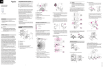
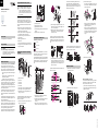
A Sensitivity controller
B Switching duration controller
C Brightness threshold controller
D Functional display, lights up each time movement is
detected
E Brightness sensor, must not be covered
Selecting the installation site
Explanation of the symbols used
• small animals.
Correct
• rooms flooded with light where the light is reflected on
objects (e.g. the floor), which can be the cause of rapid
changes in temperature.
Not optimal
DANGER
Risk of fatal injury from electrical current.
All work carried out on the unit may only be performed by skilled electricians. Observe the regulations valid in the country of use.
Connections, displays and operating
elements
B
The ARGUS 220 Advanced (hereafter called ARGUS) is
a movement detector for indoors and outdoor use.
The ARGUS registers moving sources of heat within its
range, e.g. people, and switches the loads connected
whenever it detects a movement. This could include:
– ohmic loads (e.g. 230 V incandescent and halogen
lamps)
– inductive loads (e.g. low-voltage halogen lamps
with inductive transformer)
– capacitive loads (e.g. electronic transformers)
Surface monitoring of 220° for larger house fronts and areas of the house (max. range of 16 m) is combined with
a 360° short-range zone with a radius of approx. 4 m.
The operating elements for setting the brightness threshold, switching duration and sensitivity are located under
the cover plate for protection.
The ARGUS can be mounted on the wall or ceiling and
also on to corners or fixed pipes with the mounting
bracket (art. no. MTN5652 ..) which is available as an accessory.
C
H
In principle, you should not mount the luminaire underneath the ARGUS. The radiated heat from the luminaire
can influence the function of the movement detector and
lead to a permanent lighting circuit under certain conditions.
F
When selecting a suitable installation site, you should
take a number of factors into account so that the movement detector operates optimally.
2,5
0
0,8 m
4
0
2
4
6
14
F
12
E
D
A Wall connection box
B Top section
4 Mount the wall connection box.
F A minimum distance of 5 m should be maintained
between the luminaire and the movement detector.
If this distance cannot be achieved, you can use the
segments provided to "mask" the light source from
the area of detection.
The integrated functional display lights up when movement is detected and thus simplifies the alignment of the
device at the installation site.
The ARGUS operating elements are protected under the
cover plate. The arrow's position on the controllers
shows you the set values.
The area of detection can be adapted to the local conditions due to the horizontally, vertically and axially adjustable sensor head. You can also block unwanted zones or
sources of interference (e.g. trees) from the area of detection using the masking segments provided.
1 Push up the cover plate until you feel it hit the stop
(approx. 5 mm) and pull it off.
Installing the ARGUS on the ceiling
OK
2
D Sensor head
H Terminal block for the connecting cable and for locating the contact pins
1 Release both screws and remove the wall connection box from the device.
C
4
0
G Cable routing for connecting cable from behind
If possible, install the movement detector sideways to the
direction of movement.
ARGUS installation
6
2
F Cable routing for connecting cable from underneath
10 12 14 16 m
B
8
C Cover plate
E Contact pins
B
A
10
8
A
If you wish to attach several movement detectors, install
them so that the detection areas of the individual movement detectors intersect each other.
OK
m
G
– Feeding in the connecting cable from below: Cut
the rubber insert B supplied according to the cable thickness. Insert the rubber insert into the wall
connection box. Push the connecting cable
through.
E Maintain a distance of at least 5 m from sources of
optical interference. Use the masking segments
provided if necessary.
OK
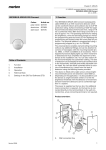
The following diagram shows the ranges of the ARGUS.
They are based on average temperature conditions at a
mounting height of 2.5 m. The range of a movement detector can fluctuate considerably at variable temperatures.
– Feeding in the connecting cable from behind:
Slide the rubber sleeve A supplied over the
stripped connecting cable.
D Select a mounting height between 2 m and 3 m. For
optimum monitoring, we recommend a height of 2.5
m on a solid and even base.
Incorrect
A
ARGUS introduction
D
D
E
In order to install the ARGUS on the ceiling, you must rotate the sensor head. Change the direction of rotation
once you have reached the end stops.
4
1 Turn the sensor head upwards as far as it will go.
6
2 Mark drill holes on the mounting surface.
8
10
OK
12
14
4
2
0
2
4
6
8
2 Turn the sensor head clockwise as far as it will go.
3 Align the sensor head.
10 12 14 16 m
A Inner security zone with an angle of detection of
360° and a radius of approx. 4 m.
B Central security zone with an angle of detection of
220° and an area of detection of approx.
9 m x 18 m.
C Outer security zone with an angle of detection of
220° and a detection area of approx. 16 m x 28 m.
OK
1
2
3
V5654-564-00 04/08
The device is fitted with a light sensor whose brightness
threshold can be set between approx. 3 and 1000 lux.
Installation options
½
|
CAUTION
If not installed correctly, the device can be
damaged by condensation.
In the case of sloping ceilings, install the device
so that spherical head is pointing down and always at an angle of 15° - 90°. When the spherical
head points downwards, any water from condensation could run down the device.
Installation of the top section of the ARGUS
• ARGUS permanently connected to the mains
Here you can infinitely set the ambient brightness level at
which the ARGUS detects movements and triggers a
switching procedure.
1
ARGUS constantly monitors its area
2
3
L
N
– Moon symbol (night operation): The ARGUS will only
detect movements during the hours of darkness (approx. 3 lux).
– Sun symbol (day and night operation): The ARGUS
detects movements up to approx. 1000 lux.
L
Type of protection IP 55 cannot be guaranteed if
the mounting bracket is not 15° - 90°.
N
The ARGUS can now be put into operation.
• ARGUS combined with two-way switch
15° - 90°
Setting the brightness threshold
Depending on the switch position, either maintained
light or automatic mode
3 LUX
Putting ARGUS into operation
1 Connect the supply voltage.
The load is switched on for approx. 10 s or for the set period. The functional display lights up for approx. 10 s.
L
N
Conducting a functional test
The brightness sensor must not be covered up.
L
Installing the ARGUS on corners and fixedpipes
You can attach the ARGUS to inner/outer corners or fixed
pipes using the Merten mounting bracket (art. no.
MTN5652..). You can feed the connecting cable to the
device from behind through the mounting bracket.
1 Set the switching duration to 1 second (left stop).
N
Setting the switching duration
Here you can set how long the loads connected to ARGUS are switched on for. When a movement is detected,
the load is switched on and stays switched on until the
set period has elapsed. Every further movement restarts
the switching duration.
40
2 Set the brightness threshold to daytime operation
(right stop).
• ARGUS combined with break contact
The ARGUS is always ready for operation. By
pressing the push-button (the power is briefly disconnected for 2–3 seconds), the ARGUS is
switched on for the set period. Every further movement increases the switching duration.
L
N
1000 LUX
3 Set the sensitivity controller to maximum (right
stop).
4 Test the functionality of ARGUS and the loads connected to it by walking to and fro in the detection area.
The functional display lights up each time movement is
detected.
80
40
3
20
3
1s
8
min
1s
8
min
1,2 sec
|
Setting ARGUS
80
20
8 min 10 sec
The ARGUS ignores the light-sensitive switch
once the load has been switched on. If the movement detector does not switch the load off again,
the reason probably is that the ARGUS constantly
detects further movements and thus keeps restarting the switching duration.
Ö S
L
N
Connecting the ARGUS
½
CAUTION
The device can become damaged.
Operation only possible with sinusoidal mains
voltages. Phase control dimmers or inverters with
square-wave or trapezoidal voltage curves will
damage the device.
|
Protect ARGUS using a 16 A circuit breaker.
|
When switching inductive loads such as transformers, relays, contactors or fluorescent lamps,
spikes occur which could lead to the load being
switched on again ("maintained light effect").
Connect a capacitor in parallel to the inductive
load to reduce these spikes.
14 mm
N
½
• ARGUS connected in parallel
Several ARGUS devices working together can
switch a lamp group when the maximum switching
capacity of one device is not exceeded. To do this,
you must reduce the sensitivity of the devices. For
technical and functional reasons, we do not advise
using more than four ARGUS devices in one group.
CAUTION
The device could become damaged.
The sensor head should only be rotated until it
reaches the stop and no further. To achieve an
angle "above" the stop, change the direction of
rotation.
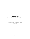
Blocking out individual areas
Using the four segments supplied, you can block out unwanted zones and sources of interference from the area
of detection.
A
1 Align the sensor head in the direction of the area
that is to be monitored.
1
L
N
L
N
L
|
9°
24°
N
12° 12°
12°
12°
2
Ensure that the brightness sensor A is not covered, as the sensitivity to light is otherwise reduced.
Technical data
Nominal voltage:
Fuse:
Max. switching
current:
Nominal output
Incandescent
lamps:
Halogen lamps:
Fluorescent
lamps:
AC 230 V ±10%, 50 Hz
Protect the ARGUS using a 16 A
circuit breaker.
16 A, AC 230 V, cosϕ = 1
AC 230 V, max. 2000 W
AC 230 V, max. 2000 W
AC 230 V, max. 1200 W, uncompensated
Capacitive load: 35 µF
Transformer load: max. 600 VA
Power consumption: < 1 W
Connecting
terminals:
for 2x1.5 mm2 or 2x2.5 mm2 rigid
conductor, stripped length 14 mm
External diameter of
one cable:
max. 14.5 mm
Angle of detection: 220°
Range:
max. 16 m
Number of levels:
7
Number of zones:
112 with 448 switching segments
Minimum mounting
height:
1.7 m
Recommended
mounting height:
2.5 m
Sensitivity:
infinitely adjustable
Light sensor:
infinitely adjustable externally,
from approx. 3 lux to approx.
1000 lux
Switching duration: externally adjustable in 6 levels of
approx. 1 sec. to approx. 8 min.
Possible settings for
sensor head
Wall mounting:
9° up, 24° down, 12° left/right,
± 12° axial
Ceiling mounting: 4° up, 29° down, 25° left/right,
± 8.5° axial
Type of protection: IP 55 at an angle of inclination
from 15° to 90°
EC directives:
Low-voltage guideline 73/23/EEC
EMC directive 89/336/EEC
Schneider Electric Industries SAS
If you have technical questions, please contact the Customer Care Center in your country.
www.schneider-electric.com
• ARGUS combined with two-circuit switch
Depending on the switch position, either manual,
automatic mode or "OFF" results. In position 1, the
luminaire is switched on by ARGUS (automatic) and
in position 2, it is switched on permanently (manual).
L
N
4° 29°
25°
25°
8,5° 8,5°
This product must be installed, connected and used in
compliance with prevailing standards and/or installation
regulations. As standards, specifications and designs
develop from time to time, always ask for confirmation of
the information given in this publication.
2 From its edge step into the area of detection to see
whether the ARGUS switches the load and the functional display as required.
Setting the sensitivity
1
L
2
Here you can infinitely set the distance up to which ARGUS detects movements (any distance up to max.
16 m).
N
• ARGUS parallel to staircase timer
Either ARGUS or the staircase timer switches the
lights on for a certain period.
L
N
N
t
On
L
N
V5654-564-00 04/08
"Through-wiring" to other loads is permitted.