1
U.motion
U.motion KNX Server
U.motion KNX Server Plus
User Manual
Art. no. MEG6501-0001 | MEG6501-0002
04/2014 VERSION 1.0.1
www.merten.com
U.motion KNX Server
User Manual
GENERAL INFORMATION
Schneider Electric GmbH c/o Merten
Gothaer Straße 29, 40880 Ratingen
www.merten.com
www.merten-austria.at
Customer care centre:
Phone: +49 2102 - 404 6000
Operating instructions, manuals and software are protected by copyright. All rights are reserved. Copying, multiplication,
translation and conversion, either partially or as a whole, is not permitted. You are allowed to make a single copy for
backup purposes.
Note: please read the manual before beginning and keep the manual for later use.
Audience: the manual has been conceived and written for users who are experienced in the use of PCs and automation
technology.
CONVENTIONS
[KEY]
Keys that are to be pressed by the user are given in square brackets, e.g. [CTRL] or [DEL]
Courier
On-screen messages are given in the Courier font, e.g. C:\>
Courier bold
input to be made by the user are given in Courier bold, e.g. C:\>DIR).
„…“ (double quotes)
Names of buttons to be pressed, menus or other onscreen elements and product names are
given within double quotes. (e.g. “Configuration”).
Symbolic
In this manual the following symbolic are used to indicate particular text blocs.
Caution!
A dangerous situation may arise that may cause damage to material.
Note.
Hint and additional notes
-2-
U.motion KNX Server
User Manual
INDEX:
1
General Overview ___________________________________________ - 5 -
1.1
Introduction ___________________________________________________________________ - 5 -
1.2
Requirements __________________________________________________________________ - 5 -
1.3
First Access_____________________________________________________________________ - 6 -
1.4
Graphical Themes _____________________________________________________________ - 8 -
1.5
Visualisation Layout ___________________________________________________________ - 8 -
1.6
Home Page __________________________________________________________________ - 10 -
2
Rooms ______________________________________________________ - 11 -
2.1
Introduction _________________________________________________________________ - 11 -
2.2
Navigation between different Rooms ______________________________________ - 11 -
2.3
Rooms in Grid View _________________________________________________________ - 12 -
2.4
Rooms in Background View _________________________________________________ - 16 2.4.1 Visualisation ________________________________________________________________ - 16 2.4.2 Customization ______________________________________________________________ - 16 -
3
3.1
Functions ___________________________________________________ - 19 Introduction _________________________________________________________________ - 19 -
3.2
Illumination __________________________________________________________________
3.2.1 Light On/Off ________________________________________________________________
3.2.2 Dimmer _____________________________________________________________________
3.2.3 RGB Light ___________________________________________________________________
- 20 - 20 - 20 - 21 -
3.3
Shadowing, Doors and Windows ___________________________________________
3.3.1 Shutters Up/Down/Stop ____________________________________________________
3.3.2 Shutters Up/Down and Percentage Value ___________________________________
3.3.3 Shutters / Curtains with Lamellae ___________________________________________
3.3.4 Door / Window Open/Closed _______________________________________________
3.3.5 Electric Locks ________________________________________________________________
3.3.6 State Door / Window Contacts______________________________________________
- 22 - 22 - 22 - 22 - 23 - 23 - 23 -
3.4
Thermoregulation ___________________________________________________________ - 23 3.4.1 Thermostats _________________________________________________________________ - 23 3.5
Energy Management ________________________________________________________ - 26 -
3.6
Audio _________________________________________________________________________ - 27 3.6.1 Multiroom-Audio-Zone _____________________________________________________ - 27 -
-3-
U.motion KNX Server
User Manual
4
4.1
5
Favourites __________________________________________________ - 28 Introduction _________________________________________________________________ - 28 -
Scheduling _________________________________________________ - 29 -
5.1
Introduction _________________________________________________________________ - 29 -
5.2
Scheduling of Objects _______________________________________________________ - 29 -
6
Scenarios ___________________________________________________ - 34 -
6.1
Introduction _________________________________________________________________ - 34 -
6.2
Execution / Interruption of Scenarios ______________________________________ - 35 -
6.3
Update of a Scenario ________________________________________________________ - 35 -
6.4
Scheduling of a Scenario ____________________________________________________ - 36 -
7
Message Central ___________________________________________ - 37 -
7.1
Introduction _________________________________________________________________ - 37 -
7.2
Notifications _________________________________________________________________ - 38 -
7.3
MessageBoard / FamilyBoard_______________________________________________ - 39 -
8
IP Cameras _________________________________________________ - 40 -
8.1
Introduction _________________________________________________________________ - 40 -
8.2
Visualisation of the Video Signal ___________________________________________ - 40 -
9
Energy Management ______________________________________ - 43 -
9.1
Introduction _________________________________________________________________ - 43 -
9.2
Consumption ________________________________________________________________ - 43 -
9.3
Loads _________________________________________________________________________ - 46 -
10
Weather ___________________________________________________ - 49 -
10.1 Introduction _________________________________________________________________ - 49 10.2 Weather Preview ____________________________________________________________ - 49 10.3 KNX Weather Station _______________________________________________________ - 50 -
11
RSS Feeds _________________________________________________ - 51 -
11.1 Introduction _________________________________________________________________ - 51 11.2 Visualisation of Feeds _______________________________________________________ - 51 -
Notes ______________________________________________________ - 52 -
-4-
U.motion KNX Server
User Manual
1 GENERAL OVERVIEW
1.1 INTRODUCTION
U.motion KNX Server and U.motion KNX Server Plus are web servers for the supervision and visualisation of home &
building automation systems, which have been realized on the basis of the worldwide KNX standard. U.motion KNX
Server allows managing of all functions of the system by accessing through client devices like U.motion Client Touch 710-15, PCs / MACs, tablets and smartphones of the last generation, within the same network or remotely via internet.
Within this manual the denomination „U.motion KNX Server“ references to both products U.motion KNX
Server and U.motion KNX Server Plus, if not named differently in the corresponding text. The differences
between the 2 server versions can be found in the corresponding datasheets, available separately.
1.2 REQUIREMENTS
This manual contains all the important information necessary to operate correctly on U.motion KNX Server within the
own system; nevertheless, it is assumed that U.motion KNX Server has first been correctly configured from the installer by
following the INSTALLATION MANUAL.
The instructions in this guide refer to the usage of U.motion KNX Server through a common desktop PC, if not noted
differently. For the access from mobile devices the usage of the U.motion Control app is recommended. For remote
control and programming purposes the access from a PC / MAC is possible (please note the different access possibilities
in U.motion KNX Server and U.motion KNX Server Plus!). In this case the following browsers can be used:
•
GOOGLE CHROME
•
APPLE SAFARI
(recommended, guarantees maximal compatibility)
-5-
U.motion KNX Server
User Manual
The usage of the following browsers is not recommended, since their compatibility can’t be fully granted:
•
MICROSOFT INTERNET EXPLORER
•
OPERA
•
MOZILLA FIREFOX
In order to access the visualisation locally, make sure your own PC / MAC is connected to the same network as U.motion
KNX Server (also via Wi-Fi, if the network supports it). However, if you want to access to U.motion KNX Server via internet,
the local network must be configured to support a remote access via port forwarding. In both cases, specific addresses
must be known:
•
For local access: the IP address of U.motion KNX Server within the network
•
For remote access via internet: the public IP address of the network to which a connection should be established
These parameters are defined by the installer or network administrator (if present) during the configuration of U.motion
KNX Server and can be obtained from them.
1.3 FIRST ACCESS
After the startup of U.motion KNX Server he will connect autonomously to the visualization. After some seconds a
loading screen will appear. On the first access, the different information is loaded into the local cache and stored there
(HTML-client cache, DB-client cache). These information are used later to navigate in the visualisation and to command
the different objects, by preloading this information is the future access accelerated and the operating is nearly at real
time. Even if the browser is closed or the device is restarted the cache will be kept and no reloading is needed. The
different cache technologies can be disabled if it is wanted, detailed information on how this is realized can be found in
the installation manual.
If not configured in another way, because of special situation, the following screen will appear on U.motion KNX Server:
-6-
U.motion KNX Server
User Manual
Highlight the box under "USERNAME" and enter the user with which you want to login. Select the field under
"PASSWORD" and enter the password corresponding to the entered user name. Finally click on LOGIN in order to access
the visualisation. With the option “REMAIN CONNECTED”, the login information can be saved and on the next access the
login will be skipped and the login will be made automatically. If it is wanted to login on every access the option can be
disabled by unchecking the box.
A software keyboard will appear on the screen, through which username and password can be entered on the touch
screen (if present) of the client device of U.motion KNX Server (with the finger). The keyboard will only be shown if not
configured differently.
The same screen will be shown, if an access on U.motion KNX Server is done for remote control or programming from a
PC/MAC. For such purposes a login on the system by entering username and password is always required.
The credentials of U.motion KNX Server will be defined by the installer and can be obtained from him. The
factory-set login credentials are:
Username
Password
Description
user
user
Basic user: can use the visualisation of U.motion KNX Server, but has only
very limited access to the configuration of U.motion KNX Server.
manager
manager
User with access to the most configuration parameters of U.motion KNX
Server, but not to the administrative configurations
admin
admin
System administrator: has full access to the visualisation and configuration.
Hint: If not defined differently by the installer, usernames and passwords are configured in LOWER CASE letters.
-7-
U.motion KNX Server
User Manual
1.4 GRAPHICAL THEMES
U.motion KNX Server provides several THEMES for the graphical interface of the visualisation. The different THEMES offer
the same functionality and the same layout, but differ in color, symbols, etc. The desired THEME can be set in the
configuration area of U.motion KNX Server, as described in the INSTALLATION MANUAL. The following screenshots show
the HOME page of the visualisation area in different THEMES:
1.5 VISUALISATION LAYOUT
Once logged in, the HOME screen will be shown:
The HEADER at the top of the page contains the following elements:
-8-
U.motion KNX Server
User Manual
•
Logo of U.motion Control
•
HOME button, allows a quick return to the HOME page from every page
Button to show/hide the NAVIGATION MENU:
•
NAVIGATION MENU is closed, a click on this button opens it
NAVIGATION MENU is open, a click on this button closes it; furthermore a swipe gesture to the left over the
navigation menu can be used to close it.
The NAVIGATION MENU appears on the left side of the screen and - as mentioned above – can be shown or hidden by
using the corresponding button:
The button in the upper right corner permits to open a context menu with the following options:
Starts the cleaning mode. All inputs on the screen of the client device are ignored for 30 seconds;
the glass of a touch screen can be cleaned easily without have to fear unwanted actions in the
visualisation. This option is only available when it is enabled in the ADMINISTRATION of U.motion
KNX Server; detailed information can be found in the U.motion KNX Server INSTALLATION GUIDE.
Permits to access the ADMINISTRATION (configuration area) of U.motion KNX Server, as explained
in the INSTALLATION GUIDE
Performs the logout of the current user and in this way permits to login with another user
-9-
U.motion KNX Server
User Manual
1.6 HOME PAGE
In addition to the already presented elements, the HOME page of the visualisation also offers the following information:
•
Current WEATHER data and forecasts for the next two days (requires that an active internet connection is
available and that the locality for the weather information has been set correctly in the U.motion KNX Server
configuration)
•
Date and time synchronized with the values of U.motion KNX Server
•
The configured entries within the navigation menu
If the WEATHER function has been configured correctly, the background image of the HOME page is updated depending
on the current weather data. Alternatively, a static background image can be configured.
All elements of the HOME page can be hidden / shown through the configuration area of U.motion KNX
Server, as described more in detail within the INSTALLATION MANUAL. For this reason, the HOME page can
also appear in a different way, if the installer previously changed these parameters.
If the displayed time / date are not congruent with the values of your PC / MAC, please make sure that the
values have been set correctly in U.motion KNX Server; the time can be set either manually or – if an internet
connection is available - it can also be synchronized automatically. More information can be found in the
INSTALLATION MANUAL.
- 10 -
U.motion KNX Server
User Manual
2 ROOMS
2.1 INTRODUCTION
U.motion KNX Server allows navigation structured in rooms, through which all functions of the system can be accessed.
The individual pages must be created by the installer in the configuration area of the U.motion KNX Server, as described
in the INSTALLATION MANUAL. The rooms are freely configurable and therefore they can also contain functions, which in
the installation must not necessarily be part of the selected room. For detailed information about the different rooms and
the included functions present in your project, please contact your installer.
2.2 NAVIGATION BETWEEN DIFFERENT ROOMS
Depending on the amount and type of the rooms in the visualisation, the navigation can be structured in one or more
levels; if only one level is used, all created rooms are listed in the “ROOMS” entry in the NAVIGATION MENU.
- 11 -
U.motion KNX Server
User Manual
In this case, if an entry is selected, the corresponding room is displayed and the NAVIGATION MENU is closed:
By reopening the menu and clicking on the BACK button it is possible to return to the list of the rooms and from there,
either another room can be selected or alternatively it is possible to return back to the main menu (in this case the HOME
page is displayed).
If the visualisation instead is structured on multiple levels, the NAVIGATION MENU will show a list of "sub-rooms" when a
main room is opened. If the chosen room contains graphic content, it is displayed and the contained functions can be
accessed immediately. If no content has been defined, the NAVIGATION MENU will show the contained rooms, while the
content of the displayed page will not change. Also here, by clicking on the BACK button it is possible to navigate back to
previous pages / menus.
2.3 ROOMS IN GRID VIEW
The room pages can represent the configured content in different ways. The most common view mode is the GRID view,
which lists the contained objects in tabular form. The GRID view can also include an image file, which can be placed either
on top, on the left, on the right side or as background of the page:
- 12 -
U.motion KNX Server
User Manual
ROOM IN GRID VIEW WITH IMAGE ON TOP
ROOM IN GRID VIEW WITH IMAGE ON THE RIGHT
- 13 -
U.motion KNX Server
User Manual
ROOM IN GRID VIEW WITH IMAGE IN BACKGROUND
In all variants of the GRID view the objects are automatically positioned within the available space: depending on the
window width, more or less columns are displayed. For this reason, the representation of the same page can vary from
device to device because of the different screen resolutions, since the objects are arranged depending on the window
width. This has the advantage that you don’t have to worry about adapting the pages for different resolutions.
In the GRID view the functions are displayed within a "box", which provides a series of information and buttons.
Depending on the object type and the configuration made by the installer, the boxes can be shown in a different way, in
order to meet best the requirements for the single operations.
The graphic of the box of a “Light On/Off” function is shown below:
Icon
Name
Buttons
- 14 -
Scheduling
Datalog
Scenario
U.motion KNX Server
User Manual
The ICON represents the intended purpose of the object in a graphical way and changes depending on the current state
of the object (on, off, open, close etc.). The NAME describes the function of the object and allows an easy identification of
the function within the system.
The STATUS-ICONS on the right show information about the object itself:
•
Scheduling: active when the object is associated with a time schedule and is therefore controlled by a timer
•
Datalog: active when the object is logged and a graphic history of the object is traced
•
Scenario: active when the object is part of a scenario and is controlled together with other objects
In the lower part of the box some BUTTONS can be found, through which the object can be controlled. Those are directly
dependent on the object type: the previous example of the "Light On/Off" function has buttons to turn on or off the
associated light (the button that corresponds to the active state is highlighted). In the case of blinds or – more in general
- motor controls, three buttons are available (move up, move down and stop):
If a dimming function is used, it is possible to turn on and off the light, and in addition through a slider element the
brightness value can be changed:
A list of the various types of functions and their boxes can be found in the chapter "FUNCTIONS" of this manual.
- 15 -
U.motion KNX Server
User Manual
2.4 ROOMS IN BACKGROUND VIEW
2.4.1 VISUALISATION
In alternative to the GRID view, the rooms can also be displayed in the BACKGROUND view. In this case, an image file can
be defined as background image for the related room; afterwards it is possible to position the individual functions
directly on the image, as shown in the following screenshot:
Normally, only the icons of the functions are displayed in this view mode (and in some case a value directly below the
icon). Clicking on the icon, the box of the related function is displayed, which shows the same information as in the GRID
view. If another object is clicked or the current page is left, the box is closed automatically. In addition, the box closes by
itself after a few seconds.
Some objects (e.g. “Light On/Off”) behave slightly different when they are displayed in BACKGROUND view: a click on the
icon will trigger directly an action on the object, depending on the current state of the object (if the light is turned on, it
will be turned off and vice versa). This allows a faster and easier usage of objects that only use a toggle function (on or
off).
2.4.2 CUSTOMIZATION
If the logged in user has appropriate permissions, he can change the content of a room in BACKGROUND view in the
following way:
•
Open the desired room
•
Open the context menu through the appropriate button in the upper right corner
•
Click on the button "Edit background"
•
Wait until you see the CUSTOMIZATION MENU on the left side (replacing the normal content of the
NAVIGATION MENU)
- 16 -
U.motion KNX Server
User Manual
When you first access the page in editing mode, all the objects will be located in the upper left corner. Simply click on the
first object and drag it to the desired location within the page. Repeat this process for all objects. The currently selected
object is identified by a red border; it is also possible to select multiple objects by holding down the CTRL key and to
move them simultaneously.
If at least one object is selected, in the CUSTOMIZATION MENU the following actions can be performed:
•
Show / hide the shadow of the function (box that appears around the icon of the function); if the shadow is
disabled, the icon becomes transparent
•
Show / hide the label of the function even when the box is closed
A special case occurs when a room contains other rooms ("sub-rooms"): in this case the contained rooms are represented
by an empty box. This box can also be moved to the desired position like other objects and it's possible to change also
the size of the box through the elements displayed on the borders of the box (the pointer turns into a pad, if these
elements are hovered). The box can also be kept fully transparent by using the option "Hide Shadows" (with the
exception of a slight edge, which appears only in editing mode for orientation purposes):
- 17 -
U.motion KNX Server
User Manual
In this way transparent, TOUCH-SENSITIVE areas can be created, which can be used to access to the sub-rooms: after
termination of the editing of the room, a click in the area covered by the box of the desired sub-room, will open the page
of the sub-room inside the visualisation.
Other objects can be placed directly on such TOUCH-SENSITIVE areas. In this case, a click on the icon commands the
object, while a click beneath the object (on the TOUCH-SENSITIVE area) will open the related room’s page.
If the option "Show Title" is enabled for such an area, the name of the room will be shown in the center of the area.
If you want to stop the editing of a room, this can be done either by clicking the SAVE button or by clicking the CANCEL
button (discards all changes).
- 18 -
U.motion KNX Server
User Manual
3 FUNCTIONS
3.1 INTRODUCTION
U.motion KNX Server allows not only the navigation through rooms, but also a navigation structured by object types via
the "FUNCTIONS" entry in the NAVIGATION MENU. The provided functions are:
•
SYSTEM
•
ILLUMINATION
•
CIMATE
•
SHADING
•
ENERGY-MANAGEMENT
•
WEATHER
Some of these entries could be disabled in your project, depending on the configuration made by the installer.
If a function entry is selected from the NAVIGATION MENU, a GRID view page showing all objects assigned to the
corresponding function type will appear. The handling of such a page is identical to the handling of a page in GRID view
without image.
If a function page contains a large number of objects, it is possible to scroll within the displayed page; depending on the
used device, either the mouse wheel (if accessed from a PC / Mac) or scroll gestures (for touch devices) can be used for
this purpose.
The following pages show the primary object types and their representation / usage within the pages of U.motion KNX
Server.
- 19 -
U.motion KNX Server
User Manual
3.2 ILLUMINATION
3.2.1 LIGHT ON/OFF
The “Light On/Off” – function is shown in the visualisation as shown below:
The buttons “ON” and “OFF” permit to control the connected light; the button, which corresponds to the current state of
the object is highlighted in a different color (furthermore, the icon in the upper left corner shows the current status, too).
In the software several icons are available for illumination; each icon shows a different illumination device:
Light - generic
Lamp
Spot
Standard lamp
3.2.2 DIMMER
Dimming functions are represented in the software through the following box:
The buttons "ON" and "OFF" permit to switch the light on and off directly. Using the slider scale, the brightness of the
light can be set. If the light is controlled through the “ON” or “OFF” button, the slider scale is automatically refreshed. In
addition, the brightness value is shown under the icon in the upper left corner and also the brightness of the icon itself
changes with the current dimming value.
- 20 -
U.motion KNX Server
User Manual
3.2.3 RGB LIGHT
This special object allows the control of light points with RGB control; these objects are represented in the rooms and
function pages in the following way:
In the lower left side of the box the last set color is shown, while the button on the right side opens the following pop-up
window:
Through the displayed graphic elements it is possible to set the desired color of the related RGB light in a simple way:
while the ring permits to select the color spectrum, the rectangle permits to tune brightness and saturation of the color. If
available, also the brightness of the RGB light itself can be adjusted through the slider scale at the bottom.
- 21 -
U.motion KNX Server
User Manual
3.3 SHADOWING, DOORS AND WINDOWS
3.3.1 SHUTTERS UP/DOWN/STOP
These object types allow the operation of motor control objects (e.g. blinds, shutters) by using the "UP" and "DOWN", as
well as the interruption of the operation using the “STOP” button:
The buttons "UP" and "DOWN" are highlighted in a different color, depending on the last command sent; the “STOP”
button will not display any state, but show up a color mark for a few seconds, when it is pressed.
3.3.2 SHUTTERS UP/DOWN AND PERCENTAGE VALUE
These object types allow the operation of motor control objects (e.g. blinds, shutters) by using the "UP" and "DOWN", as
well as a percentage configuration going from 0% (totally open) up to 100% (totally closed):
3.3.3 SHUTTERS / CURTAINS WITH LAMELLAE
These object types allow the operation of motor control objects with lamellae (e.g. blinds, shutters, curtains, etc.) by using
the "UP" and "DOWN" buttons (movement) and “CLOSE” and “OPEN” buttons (lamellae):
- 22 -
U.motion KNX Server
User Manual
3.3.4 DOOR / WINDOW OPEN/CLOSED
Objects of this type allow the sending of an opening or closing command to an electrical lock (e.g. a window or a door):
The button corresponding to the current state of the lock is highlighted in green or red color.
3.3.5 ELECTRIC LOCKS
This object is similar to the previous object, with the difference that only the "ON" command can be sent:
In this case, the object does not show any status; only during operation a short color change will be performed. The
object will send the open command for the time period, which has been set by the installer during the configuration of
the system (usually a few seconds).
3.3.6 STATE DOOR / WINDOW CONTACTS
These objects show the state of door and window contacts:
In this case, no commands can be sent: therefore the lower part of the box contains no buttons, but just shows the state
of the associated contact.
3.4 THERMOREGULATION
3.4.1 THERMOSTATS
The administration of thermostats within the visualisation of U.motion KNX Server strongly depends on the manufacturer
/ type of the used thermostat and their respective configuration. The instructions in this manual refer to the most
common configuration methods and try to represent the maximum of available objects. In your own configuration, some
of the functions presented may not be used.
- 23 -
U.motion KNX Server
User Manual
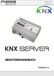
The following graphic shows the typical box of a thermostat within the rooms or function pages of the visualisation:
In the display on the left side the measured temperature of the thermostat is shown, which is also shown directly below
the icon (useful for BACKGROUND view, where the box is initially closed). By clicking on the button on the right side, the
following pop-up window will appear:
Measured temperature
Current setpoint
State of:
heating /
cooling /
ventilation
Operating mode
Category tabs
Scheduling button
Setpoints of the operating modes
The “DISPLAY” in the upper area contains the following information about the thermostat:
MEASURED TEMPERATURE
Measured ambient temperature of the thermostat
CURRENT SETPOINT
Temperature setpoint, towards which the thermostat
regulates the temperature; depends from the selected
operating mode of the thermostat.
STATE HEATING / COOLING / VENTILATION
State icon, which shows the active mode of the thermostat
(heating, cooling, ventilation)
- 24 -
U.motion KNX Server
User Manual
The buttons below the display are used to change the OPERATING MODE of the thermostat. Depending on the type of
thermostat, different setpoints can be adjusted for heating, cooling and ventilation (if present).
The tabs on the category selection (if configured) determine the items displayed in the bottom area of the object:
HEATING
Allows the configuration of the several heating setpoints for the different operating
modes of the thermostat
COOLING
Allows the configuration of the several cooling setpoints for the different operating
modes of the thermostat
VENTILATION
Permits to control the ventilation (automatic or manually); by selecting manual control,
the single ventilators can be controlled.
The following screenshot shows an example of a thermostat with inactive "VENTILATION":
The "SCHEDULE" button (if enabled by the installer) allows time scheduling of the thermostat functions; for further details, please refer to the chapter “SCHEDULING of this manual.
- 25 -
U.motion KNX Server
User Manual
3.5 ENERGY MANAGEMENT
U.motion KNX Server provides various types of objects, through which various energy information (which are provided
from KNX energy counters installed in the system) can be represented in the software. Furthermore, the parameters of
load-controllers can be actively controlled. The following graphics show some examples of the existing object types:
These objects can be connected to rooms, just like all other objects, in order to show individual consumptions, or they
can also be used in combination with load controllers for the representation of the total consumption. Additionally,
U.motion KNX Server offers a separate area called “ENERGY MANAGEMENT”, accessible through the NAVIGATION MENU.
This section shows a complete overview of the current power consumption. For more information about the ENERGY
MANAGEMENT, please refer to the appropriate chapter in this manual.
- 26 -
U.motion KNX Server
User Manual
3.6 AUDIO
3.6.1 MULTIROOM-AUDIO-ZONE
With U.motion KNX Server it is possible to manage the single zones of a compatible multi-room audio system using the
following pop-up window:
The pop-up can offer the following action buttons (some of them could be missing in your configuration, since the
buttons depend on the functionalities provided by the installed audio system):
•
•
•
•
•
PLAY/PAUSE
STOP
PREVIOUS / NEXT track
Playback mode: NORMAL, RANDOM or REPEAT
VOLUME control
- 27 -
U.motion KNX Server
User Manual
4 FAVOURITES
4.1 INTRODUCTION
With the FAVOURITES page U.motion KNX Server offers a special page, which can contain the most frequently used
functions. The FAVOURITES page can be accessed directly from the NAVIGATION MENU or the HOME page.
In order to add an object to the FAVOURITES, please follow the steps below:
•
Open a page containing the target object in GRID view (room or function page)
•
Click on the icon of the function and hold down the mouse / finger for a few seconds; instead of the command
buttons two more buttons ("SCHEDULING" and "FAVOURITES") are shown, where the FAVOURITES button is
highlighted when the object already is present in the FAVOURITES.
•
Enable / Disable the FAVOURITES button, depending on whether the object should be added or removed
By clicking on the button, its color will change (highlighted = object is already linked to the FAVOURITES,
not highlighted = object is not linked to the FAVOURITES). After a few seconds, the buttons will disappear and the object
will reappear in its original form.
- 28 -
U.motion KNX Server
User Manual
5 SCHEDULING
5.1 INTRODUCTION
U.motion KNX Server allows the time scheduling of all objects that are present in the rooms and function pages of the
visualisation. If a time schedule is active, U.motion KNX Server controls the related objects, even if no one is in the
building. This chapter shows how a schedule can be established, from a simple daily scheduling to a complex planning
with the year calendar.
5.2 SCHEDULING OF OBJECTS
To set up a time scheduling, click on the icon of the target function and hold down the mouse / finger down for a few
seconds (works with both GRID view and BACKGROUND view). As mentioned in the previous chapters, additional buttons
will appear, through which the scheduling can be accessed:
When using objects with pop-up windows, such as thermostats, the time scheduling can also be accessed through the
appropriate button in the pop-up window:
- 29 -
U.motion KNX Server
User Manual
In both cases a second pop-up window will appear (initially without any time scheduling and therefore empty), as shown
in the screenshot below:
- 30 -
U.motion KNX Server
User Manual
In order to create a new scheduling, please click on the "+" symbol: for each scheduling, a new line will appear in the
window; the following screenshots refer to the time scheduling of the operating mode of a thermostat.
The individual time schedules are always based on daily activities (from 00:00 to 23:59). By clicking on the EDIT button
(tool icon), the property window of the selected time scheduling will appear:
- 31 -
U.motion KNX Server
User Manual
In the upper area, a label can be assigned to the scheduling, through which it can be easily identified in the visualisation.
It is recommended to define the label in a way that it’s possible to easily understand what actions the scheduling
contains, to facilitate the configuration and usage of the scheduling.
Example: “Irrigation Monday-Friday” or “Garden lights weekend”
The section "DAILY SCHEDULING" allows the configuration of one or more actions that should be executed during the
period of a single day. To add new actions, simply click on the "+"-button and for each action configure the following
parameters:
•
Hour
•
Minute
•
Action to execute
•
Value to set (if available)
The section "CALENDAR-BASED SCHEDULING" defines whether the configured actions will be executed on one or more
days of a week or ALTERNATIVELY on one or more days selected through the yearly calendar. In the case of the weeklyscheduling, the individual days of the week can be selected by clicking the appropriate buttons at the bottom.
The following screenshot shows the scheduling of a thermostat with multiple daily actions, active from Monday to Friday:
To save the scheduling, simply click on the SAVE button in the upper right corner. If all changes should be discarded,
simply click on the CANCEL button next to the SAVE button.
- 32 -
U.motion KNX Server
User Manual
To create a complete yearly calendar, the single days on which the defined actions should take place can simply be
selected in the calendar, which is available in the section "YEARLY" of the "CALENDAR-BASED SCHEDULING". This type of
scheduling also allows the "omission" of individual days to take care about holidays or vacations in the weekly scheduling.
If several individual schedules are defined for the same day, U.motion KNX Server will give priority to the
schedules of type "YEARLY", since - as already mentioned - the creation of exceptions, e.g. for holidays, can be
configured only within this type of scheduling. If no yearly scheduling is defined, the weekly scheduling is
executed without deviations.
ATTENTION: within the same scheduling it is ONLY possible to use EITHER the WEEKLY OR the YEARLY
calendar scheduling (not both!). Exceptions, as described above, must always be configured in a SEPARATE
weekly or yearly scheduling!
It is furthermore possible to disable individual schedules and therefore prevent their execution, without having to delete
the defined schedules. This can be done through the button on the right side of the time scheduling (green icon =
schedule is active, red icon = schedule is disabled).
In the screenshot above the scheduling "HOLIDAYS" is disabled and is therefore ignored by the system.
- 33 -
U.motion KNX Server
User Manual
6 SCENARIOS
6.1 INTRODUCTION
U.motion KNX Server allows the automatic execution of different commands; these sequences are called "SCENARIOS".
The entry "SCENARIOS" in the NAVIGATION MENU displays all the scenarios that have been configured in the project by
the installer. The following screenshot shows an example of the SCENARIOS page:
- 34 -
U.motion KNX Server
User Manual
6.2 EXECUTION / INTERRUPTION OF SCENARIOS
The box of a scenario provides the following buttons:
PLAY
Starts the command sequence defined in the scenario
STOP
Stops the command sequence (premised the scenario is running)
UPDATE
Permits to update the commands configured in the scenario with the current states of the
related objects; the procedure is explained more in detail in the connection
Since the execution of the actions of a scenario may include also time delays (due to wait commands added by the installer), the scenario may remain in PLAY mode for a longer time. In this case, the scenario can be interrupted with the
STOP button.
The interruption of a scenario does NOT reset the actions already executed to the state before the execution
of the scenario. This means that actions that should be reset after an interruption of the scenario must be
reset MANUALLY.
A typical example are irrigation scenarios: these usually include the delayed opening and closure of the irrigation valves; if such a scenario is stopped before its completion, the already opened irrigation valves remain
open and must be closed MANUALLY through the appropriate KNX object in the visualisation of U.motion
KNX Server.
6.3 UPDATE OF A SCENARIO
If the UPDATE button of a scenario is pressed, the scenario for all contained objects assumes the current state in the
system as new reference value for future executions of the scenario. This operation can last a few seconds, depending on
the amount of objects contained in the scenario. Once the UPDATE procedure is finished, the UPDATE button returns to
its original condition.
The UPDATE button could also be disabled for the scenarios in your configuration. In this case, your installer
blocked the update of the scenarios. This may be especially the case for scenarios that commands the same
object multiple times. In this case, the update process would cause a malfunction of the scenario.
- 35 -
U.motion KNX Server
User Manual
6.4 SCHEDULING OF A SCENARIO
The scenarios can be used like any other objects of the software and therefore can also be scheduled. In this case, by
clicking on the icon of the scenario and holding the mouse button / finger for several seconds, as mentioned already
before, more buttons are shown, through which the scheduling can be activated or the scenario can be added to the
favourites:
- 36 -
U.motion KNX Server
User Manual
7 MESSAGE CENTRAL
7.1 INTRODUCTION
The message central of U.motion KNX Server allows the centralized management of system-generated messages. Those
can either be generated by events / alarms in the system or by the user.
The message central is always available through the NAVIGATION MENU or the HOME page. If there are unread
messages, an icon is displayed including the number of unread messages, as shown in the following screenshot:
- 37 -
U.motion KNX Server
User Manual
7.2 NOTIFICATIONS
The section "NOTIFICATIONS" of the message central displays a list of all messages generated by U.motion KNX Server,
which are triggered depending on the configuration within the system (e.g. by events, alarms or faults).
The message central will only be opened automatically when a notification of type "ALARM" is received, if not configured
differently. Other messages are shown only through the icon in the NAVIGATION MENU or the HOME page; the user
must manually click on "NOTIFICATIONS" to check out those messages:
The different levels / types of notifications are represented through different colors. If a message was read, it can be
deleted using the appropriate button on the right side.
If several messages are displayed, they can be deleted all together by using the DELETE button in the upper right corner.
- 38 -
U.motion KNX Server
User Manual
7.3 MESSAGEBOARD / FAMILYBOARD
The MESSAGE BOARD permits to enter messages directly through the touchscreen (for touch devices):
At completion of the message, also here an icon is displayed informing about the presence of a new message; it appears
in the NAVIGATION MENU / the HOME page on the entry MESSAGE BOARD; the icon remains visible also after closing
the message central window.
The messages on the MESSAGE BOARD are only displayed on the device on which the message has been
entered and not on other devices in the network. Furthermore, these messages will be lost if the browser is
closed or the visualisation is updated.
- 39 -
U.motion KNX Server
User Manual
8 IP CAMERAS
8.1 INTRODUCTION
U.motion KNX Server permits to display video streams of compatible IP cameras, video servers and video recorders inside
the pages of the visualisation. The video streams can be accessed from within the local network or also by remote access
through internet.
8.2 VISUALISATION OF THE VIDEO SIGNAL
By selecting the entry "VIDEO SURVEILLANCE" in the NAVIGATION MENU, a list of the configured cameras is displayed. If
one of them is selected, a pop-up window containing the video stream of the selected camera will be shown (the performance of the stream depends on camera type, the quality of the network and the performance of the client device)
:
- 40 -
U.motion KNX Server
User Manual
If you click on the top bar of the pop-up window, the window will be closed and another camera can be selected from
the NAVIGATION MENU or other pages of the visualisation can be accessed.
If the camera object was assigned to one or more rooms, it can also be displayed within the pages of the visualisation,
together with the other objects of the project, as shown below:
- 41 -
U.motion KNX Server
User Manual
A click on the camera-icon opens a pop-up window showing the related cameras video stream in the configured resolution; the result basically is the same as opening the camera through the NAVIGATION MENU.
- 42 -
U.motion KNX Server
User Manual
9 ENERGY MANAGEMENT
9.1 INTRODUCTION
The "ENERGY" section of U.motion KNX Server shows an overview of the complete energy consumption and possible
energy production (e.g. photovoltaic) of an installation. This feature requires that the necessary KNX devices are installed
in the plant, which collect energy data and provide it through the KNX bus.
This section is highly dependent on the nature of the own system and how it is configured by the installer. Therefore this
chapter shows a typical application with two KNX energy counters - one to measure the current energy consumption of
the plant and the other to measure the energy production of a photovoltaic system - as well as some loads, which are
driven by load-controls.
9.2 CONSUMPTION
By selecting the entry "ENERGY" in the NAVIGATION MENU or HOME-page and subsequently the entry
"CONSUMPTION", a page is opened containing a general power consumption overview:
- 43 -
U.motion KNX Server
User Manual
This page shows one or more energy counters which indicate the energy consumption or energy production of a
building. The color (green - orange - red) indicates graphically that the configured limits are exceeded.
By clicking on one of the energy counters, the following pop-up window is opened, which provides further details about
the energy consumption and gives access to the configurable parameters, which are organized in different TABS:
- 44 -
U.motion KNX Server
User Manual
Under each energy counter a colored box can be seen, which allows the visualisation in graphical way of the data of the
connected energy counter object. The graphs are shown in the lower part of the page:
The color of the box is the same as the one of the corresponding graph, what permits to easily recognize it even when
more than one graph is visualised. Furthermore, the box permits to change some options of the graphical representation
of the shown data:
SHOW
Shows / Hides the graph of the corresponding energy counter
COMPARE
Shows hides the comparison values, which are calculated from the average value of the lastly
measured values
RANGE
Shows / Hides the colored area which marks the range between the minimum and maximum
values of the energy counter (in dependence of the selected time period)
The lower area of the page contains the graphs of the single energy counters from the upper area. The data shown in the
graphs always refers to a certain time period, which can be selected by the user through the different TABS on the top of
the page:
TODAY
Data of the current day (from 00:00); the comparison value – if enabled – is calculated
from the average of the daily values logged
YESTERDAY
Data of the previous day; the comparison value – if enabled – is calculated from the
average of the values logged the previous day
WEEK
Data of the current week (from Monday, 00:00); the comparison value – if enabled – is
calculated from the average of the weekly values logged
LAST WEEK
Data of the previous week; the comparison value – if enabled – is calculated from the
average of the values logged the previous week
MONTH
Data of the current month (from the first day, 00:00); the comparison value – if enabled –
is calculated from the average of the monthly values logged
LAST MONTH
Data of the previous month; the comparison value – if enabled – is calculated from the
average of the values logged the previous month
YEAR
Data of the current year (from the first day, 00:00); the comparison value – if enabled – is
calculated from the average of the yearly values logged
LAST YEAR
Data of the previous year; the comparison value – if enabled – is calculated from the
average of the values logged the previous year
- 45 -
U.motion KNX Server
User Manual
The following screenshot explains the different elements within the visualisation area of the graphs:
Graph explanation
incl. total consumption
of the current
time period
Energy values
of the current
time period
Range
of the current
time period
Average values
of the current
time period
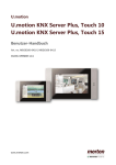
9.3 LOADS
This section shows the energy consumption of individual loads in real time. Furthermore, the priorities of the load control
system can be displayed (if configured / available), as shown in the following screenshot:
Selector Load control (if more than one present)
Energy counter
Loads
- 46 -
U.motion KNX Server
User Manual
The energy counter in the upper area shows the total consumption of the system in relation to the configured limits of
the load control. On the right side two icons inform about the current state of the load control logic (idle or active) and
the current priority value:
Current power value
Min. and max. limit
Under normal circumstances the priority value equals 0; if, however, the configured maximum limit is exceeded, the
priority is increased on 1 and all loads connected to this priority are disabled. If the consumption still remains over the
limit, the priority is furthermore increased (and corresponding loads are switched off), until the maximum priority value is
reached.
If instead the consumption goes back below the configured minimum limit, the load control starts acting in the opposite
way; the priority value is decreased and previously disabled loads are turned back on.
The limits of the load control can be changed easily through the pop-up window, which appears when the energy counter
of the total consumption is clicked:
- 47 -
U.motion KNX Server
User Manual
The single loads, in contrast to the overall consumption, show the following information:
Priority
Auto/Man
Current power consumption (if available)
Also in this case, the properties of the single loads (for example the priority) can be changed through the pop-up
window, which is shown when clicking on the corresponding energy counter:
As you can see in above screenshot, a load can also be put into a MANUAL mode; in this case, the load is not disabled by
the load control of U.motion KNX Server but can only be controlled manually by the user (this can be helpful in order to
exclude loads temporarily from forced switch-off).
- 48 -
U.motion KNX Server
User Manual
10 WEATHER
10.1
INTRODUCTION
U.motion KNX Server allows quick and easy display of weather data, which are obtained either over the internet or – if
available - from a connected KNX weather station.
10.2
WEATHER PREVIEW
By selecting the entry "WEATHER" in the NAVIGATION MENU or in the HOME page, a pop-up window will be opened,
which displays the current weather data and the weather forecast of the configured location:
- 49 -
U.motion KNX Server
User Manual
10.3
KNX WEATHER STATION
If a KNX weather station is installed in the system and integrated into U.motion KNX Server correctly by the installer, in
the WEATHER pop-up window it will be possible to select a second tab containing the data provided by the KNX weather
station:
The displayed values depend on the data provided by the weather station.
- 50 -
U.motion KNX Server
User Manual
11 RSS FEEDS
11.1
INTRODUCTION
U.motion KNX Server permits to embed messages from one or more RSS feeds from the Internet. The RSS feeds can be
accessed through the entry “RSS NEWS” in the NAVIGATION MENU or the HOME page.
11.2
VISUALISATION OF FEEDS
After selecting the entry "RSS NEWS" the following pop-up window will appear:
Depending
on
the
number of configured
RSS feeds (max. 5) you
can switch between the
single tabs. Within a feed
it is possible to scroll up
and down with a mouse
wheel (on PC / MAC) or
through
touch-gestures
(for touch devices).
- 51 -
U.motion KNX Server
User Manual
NOTES
- 52 -