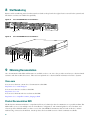
1
Quick Start Guide
Cisco AS5350XM and Cisco AS5400XM Universal Gateways
INCLUDING LICENSE AND WARRANTY
1
Cisco 90-Day Limited Hardware Warranty Terms
2
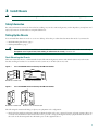
Documents, Equipment, and Tools
3
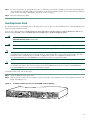
Install Chassis
4
Install Modules
5
Connect Cables
6
Power Up the Universal Gateway
7
Perform Initial Configuration
8
Slot Numbering
9
Obtaining Documentation
10 Documentation Feedback
11 Cisco Product Security Overview
12 Obtaining Technical Assistance
13 Obtaining Additional Publications and Information
1 Cisco 90-Day Limited Hardware Warranty Terms
There are special terms applicable to your hardware warranty and various services that you can use during the warranty period.
Your formal Warranty Statement, including the warranties and license agreements applicable to Cisco software, is available on
Cisco.com. Follow these steps to access and download the Cisco Information Packet and your warranty and license agreements
from Cisco.com.
1. Launch your browser, and go to this URL:
http://www.cisco.com/univercd/cc/td/doc/es_inpck/cetrans.htm
The Warranties and License Agreements page appears.
2. To read the Cisco Information Packet, follow these steps:
a. Click the Information Packet Number field, and make sure that the part number 78-5235-03A0 is highlighted.
b. Select the language in which you would like to read the document.
c. Click Go.
The Cisco Limited Warranty and Software License page from the Information Packet appears.
d. Read the document online, or click the PDF icon to download and print the document in Adobe Portable Document
Format (PDF).
Note
You must have Adobe Acrobat Reader to view and print PDF files. You can download the reader from Adobe’s
website: http://www.adobe.com
3. To read translated and localized warranty information about your product, follow these steps:
a. Enter this part number in the Warranty Document Number field:
78-5236-01C0
b. Select the language in which you would like to read the document.
c. Click Go.
The Cisco warranty page appears.
d. Review the document online, or click the PDF icon to download and print the document in Adobe Portable Document
Format (PDF).
You can also contact the Cisco service and support website for assistance:
http://www.cisco.com/public/Support_root.shtml
Duration of Hardware Warranty
Ninety (90) days.
Replacement, Repair, or Refund Policy for Hardware
Cisco or its service center will use commercially reasonable efforts to ship a replacement part within ten (10) working days after
receipt of a Return Materials Authorization (RMA) request. Actual delivery times can vary, depending on the customer location.
Cisco reserves the right to refund the purchase price as its exclusive warranty remedy.
To Receive a Return Materials Authorization (RMA) Number
Contact the company from whom you purchased the product. If you purchased the product directly from Cisco, contact your
Cisco Sales and Service Representative.
Complete the information below, and keep it for reference:
Company product purchased from
Company telephone number
Product model number
2
Product serial number
Maintenance contract number
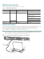
2 Documents, Equipment, and Tools
User Documentation
All of the documents described here are available online and on the Documentation DVD. To be sure of obtaining the latest
information, you should access the online documentation.
Note
The information in this document applies to the Cisco AS5350XM and Cisco AS5400XM universal gateways.
To access online user documentation:
From Cisco.com at http://www.cisco.com, choose Technical Support & Documentation.
Cisco AS5350XM and Cisco AS5400XM Universal Gateway Documentation
Regulatory Compliance and Safety Information
The Regulatory Compliance and Safety Information document provides essential safety information applicable to your universal
gateway. A printed copy of this document is shipped with this device.
You can access this document at Technical Support & Documentation > Product Support > Universal Gateways and Access
Servers > Cisco AS5300 or Cisco AS5400 Series Universal Gateways > Install and Upgrade Guides.
Hardware Installation
The chassis installation guide provides additional detailed description, installation, and cabling information.
You can access this document at Technical Support & Documentation > Product Support > Universal Gateways and Access
Servers > Cisco AS5300 or Cisco AS5400 Series Universal Gateways > Install and Upgrade Guides.
Software Configuration
The software configuration guide provides additional detailed configuration information.
You can access this document at Technical Support & Documentation > Product Support > Universal Gateways and Access
Servers > Cisco AS5300 or Cisco AS5400 Series Universal Gateways > Configuration Guides.
Cisco IOS Software Documentation
Master Index to Software Documentation
The master index provides links to topics and commands for specific Cisco IOS software releases.
You can access these documents at Technical Support & Documentation > Product Support > Cisco IOS Software > Cisco IOS
Software Release you are using > Master Index.
Configuration Guides
The Cisco IOS software configuration guides provide detailed configuration procedures and examples.
You can access these documents at Technical Support & Documentation > Product Support > Cisco IOS Software > Cisco IOS
Software Release you are using > Configuration Guides.
3
Command References
The Cisco IOS software command references provide detailed information about each command.
You can access these documents at Technical Support & Documentation > Product Support > Cisco IOS Software > Cisco IOS
Software Release you are using > Command References.
New Feature Documentation
New feature documentation contains detailed information about new features introduced in specific Cisco IOS releases.
You can access these documents at Technical Support & Documentation > Product Support > Cisco IOS Software > Cisco IOS
Software Release you are using > Feature Guides.
If you have an account on Cisco.com, you can get updated information about platform support for features by accessing Feature
Navigator at the following URL:
http://www.cisco.com/go/fn
Release Notes
Cisco IOS release notes for all platforms provide up-to-date information about specific Cisco IOS software releases.
You can access these documents at Technical Support & Documentation > Product Support > Cisco IOS Software > Cisco IOS
Software Release you are using > Release Notes.
Items Included with Cisco AS5350XM and Cisco AS5400XM Universal Gateways
• 19-inch (48.26-cm) and 24-inch (60.96-cm) rack-mount kits
• Rubber feet for desktop installation
• RJ-45-to-DB-9 female DTE adapter (labeled TERMINAL)
• RJ-45-to-DB-25 female DTE adapter (labeled TERMINAL)
• RJ-45-to-DB-25 male DCE adapter (labeled MODEM)
• RJ-45-to-RJ-45 rollover console cable
• ESD-preventive wrist strap
• Nylon cable ties
• Cable tie holder
• Grounding lug
• Cisco Information Package
Items Not Included
Individual items in this list may be required for your particular application:
• Straight-through RJ-45-to-RJ-45 cable for an Ethernet connection
• Straight-through RJ-45-to-RJ-45 cables for T1 connections
• E1 cables for E1 connections
• Ethernet hub, Gigabit Ethernet switch, or PC with a network interface card for Ethernet LAN connections
• PC running terminal emulation software for local administrative access
• Modem for remote administrative access
• One breakout cable consisting of a 36-pin connector connected to eight RJ-45 adapters for CT1/CE1 connections
• 75-ohm coaxial cable for a CT3 connection
4
3 Install Chassis
Note
The information in this document applies to the Cisco AS5350XM and Cisco AS5400XM universal gateways.
Safety Information
For safety information you need to know before working on your Cisco universal gateway, see the Regulatory Compliance and
Safety Information document that accompanied this device.
Setting Up the Chassis
You can install the chassis in a rack or set it on a desktop. Select the procedure that best meets the needs of your network:
• Rack-Mounting the Chassis, page 5
• Desktop Installation, page 7
Warning
This unit is intended for installation in restricted access areas. A restricted access area can be accessed only
through the use of a special tool, lock and key, or other means of security. Statement 1017
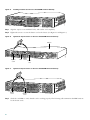
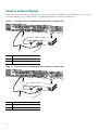
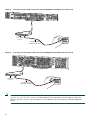
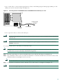
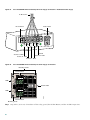
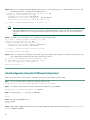
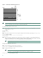
Rack-Mounting the Chassis
This section describes how to rack-mount the chassis. The universal gateway arrives with 19-inch (48.26-cm) rack-mount
brackets and larger brackets for use with a 23-inch (58.42-cm) or 24-inch (60.96-cm) rack.
Cisco AS5350XM Universal Gateway Rack-Mount Brackets
Bracket for 19-inch rack
Cisco AS5400XM Universal Gateway Rack-Mount Brackets
H6028
Figure 2
Bracket for 23-inch rack
36012
Figure 1
Bracket for 19-inch rack
Bracket for 23- or 24-inch rack
The following information will help you plan your equipment rack configuration:
• Enclosed racks must have adequate ventilation. Ensure that the rack is not congested, because each unit generates heat. An
enclosed rack should have louvered sides and a fan to provide cooling air. Heat generated by equipment near the bottom of
the rack can be drawn upward into the intake ports of the equipment above.
5
• When mounting a chassis in an open rack, ensure that the rack frame does not block the intake or exhaust ports. If the
chassis is installed on slides, check the position of the chassis when it is seated in the rack.
• Baffles can isolate exhaust air from intake air, which also helps to draw cooling air through the chassis. The best placement
of the baffles depends on the airflow patterns in the rack, which can be found by experimenting with different
configurations.
• When equipment installed in a rack (particularly in an enclosed rack) fails, try operating the equipment by itself, if possible.
Power down other equipment in the rack (and in adjacent racks) to allow the unit under test a maximum of cooling air and
clean power.
• Install the chassis and external devices to which it will connect in a contiguous stack.
Required Tools and Equipment
You need the following tools and equipment to rack-mount the chassis:
• Number 2 Phillips screwdriver (not included)
• Medium flat-blade screwdriver (not included)
• Screws for attaching the chassis to the rack (not included)
• Standard rack-mount brackets (included)
• Screws for attaching the brackets to the chassis (included)
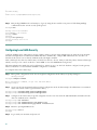
Attaching Brackets
Attach the mounting brackets to the chassis as shown, using the screws provided. Attach the second bracket to the opposite side
of the chassis.
Note
The chassis may be installed with either the front panel or the back panel facing forward.
Cisco AS5350XM Universal Gateway Bracket Installation—Front Panel Forward (19-Inch Rack)
Figure 4
Cisco AS5400XM Universal Gateway Bracket Installation—Front Panel Forward (19-Inch Rack)
H10643
35669
Figure 3
6
Installation in a Rack
Install the chassis in the rack. Rack-mounting screws are not provided. Use two screws for each side (supplied with the rack).
Installing the Cisco AS5350XM Universal Gateway in a Rack (19-Inch Rack)
Figure 6
Installing the Cisco AS5400XM Universal Gateway in a Rack (19-Inch Rack)
29034
35659
Figure 5
Desktop Installation
For desktop or shelf mounting, use the rubber “feet” shipped on a black adhesive strip with the chassis. They protect the chassis
and provide a nonskid surface.
The location of the chassis is extremely important for proper operation. Equipment placed too close together, inadequate
ventilation, and inaccessible panels can cause malfunctions and shutdowns, and can make maintenance difficult. The following
information will help you to plan the location of the chassis:
• Plan for access to both front and back panels of the chassis.
• Ensure that the room where the chassis operates has adequate ventilation. Remember that electrical equipment generates
heat. Ambient air temperature may not cool equipment to acceptable operating temperatures without adequate ventilation.
To attach the rubber feet, follow these steps:
Step 1
Locate the rubber feet that shipped with the chassis.
Step 2
Place the universal gateway upside-down on a smooth, flat surface.
Step 3
Peel the rubber feet off the black adhesive strip, and attach them adhesive-side-down at each corner of the underside of
the chassis.
Step 4
Place the universal gateway top-side-up on a flat, smooth, secure surface.
7
Caution
Do not place anything on top of the universal gateway that weighs more than 10 lb (4.5 kg). Excessive weight on
top could damage the chassis.
Chassis Ground Connection
You must connect the chassis to a reliable earth ground by using the ground lug (provided) and size AWG 6 (13 mm2) wire.
To attach the chassis ground, follow these steps:
Step 1
Strip one end of the ground wire to expose approximately 0.75 in. (20 mm) of conductor.
Step 2
Crimp the ground wire to the ground lug, using a crimp tool of the appropriate size.
Step 3
Attach the ground lug to the chassis as shown in Figure 7 and Figure 8. Use a medium flat-blade screwdriver and the
screws supplied with the ground lug. Tighten the screws to a torque of 8 to 10 in-lb (0.9 to 1.1 N-m).
Cisco AS5350XM Universal Gateway Ground Lug Attachment
82735
Figure 7
Ground lug
attachment
Cisco AS5400XM Universal Gateway Ground Lug Attachment
82734
Figure 8
Ground lug
attachment
Step 4
8
Connect the other end of the ground wire to a suitable grounding point at your site.
4 Install Modules
Note
The information in this document applies to the Cisco AS5350XM and Cisco AS5400XM universal gateways.
Note
The Cisco AS5350XM and Cisco AS5400XM universal gateways come with carrier cards and feature cards already
installed. If you are not installing additional carrier cards or feature cards, proceed to the “Connect Cables” section on
page 15.
For additional information about installing carrier cards and feature cards, see the Cisco AS5350XM and Cisco AS5400XM
Universal Gateways Card Installation Guide.
You can access this document at Technical Support & Documentation > Product Support > Universal Gateways and Access
Servers > Cisco AS5300 or Cisco AS5400 Series Universal Gateways > Install and Upgrade Guides.
Installing Carrier Cards
Caution
The carrier cards that carry the feature cards are not hot-swappable. Removing or replacing a carrier card while
the system is still powered up may cause permanent damage to electronic circuits on the card.
Warning
Do not work on the system or connect or disconnect cables during periods of lightning activity. Statement 1001
Warning
Before opening the unit, disconnect the telephone-network cables to avoid contact with telephone-network
voltages. Statement 1041
Installing a Carrier Card
If you need to install a carrier card, follow these steps:
Step 1
Warning
Make sure the chassis is powered down.
Before working on a chassis or working near power supplies, unplug the power cord on AC units; disconnect the
power at the circuit breaker on DC units. Statement 12
Step 2
Attach an ESD-preventive wrist strap.
Step 3
Slide the carrier card into the slot until it touches the backplane connector. (See Figure 9 and Figure 10.)
Install the Carrier Card in the Cisco AS5350XM Universal Gateway
36004
Figure 9
9
Install the Carrier Card in the Cisco AS5400XM Universal Gateway
37161
Figure 10
Step 4
Align the captive screws with their holes, and seat the card completely.
Step 5
Tighten the two captive screws to secure the carrier card to the chassis. (See Figure 11 and Figure 12.)
Tighten the Captive Screws on the Cisco AS5350XM Universal Gateway
36005
Figure 11
Captive screw
Captive screw
Tighten the Captive Screws on the Cisco AS5400XM Universal Gateway
37162
Figure 12
Captive
screw
Step 6
Captive
screw
If the carrier card has a blank feature card slot, install a blank cover over the open feature card slot to ensure proper
airflow inside the chassis.
Blank Feature Card Cover
36033
Figure 13
10
Step 7
For AC-powered units, reconnect the AC power cord. For DC-powered units, reinstate power at the circuit breaker. For
more information on the AC and DC power supplies, see the chassis installation guide. To access the chassis installation
guide, see the “Documents, Equipment, and Tools” section on page 3.
Step 8
Reconnect all interface cables.
Installing Feature Cards
For detailed information on installing and connecting feature cards, see the Cisco AS5350XM and Cisco AS5400XM Universal
Gateways Card Installation Guide.
You can access this document at Technical Support & Documentation > Product Support > Universal Gateways and Access
Servers > Cisco AS5300 or Cisco AS5400 Series Universal Gateways > Install and Upgrade Guides.
Warning
The telecommunications lines must be disconnected 1) before unplugging the main power connector and/or 2)
while the housing is open. Statement 89
Warning
Do not work on the system or connect or disconnect cables during periods of lightning activity. Statement 1001
Note
When you replace a feature card with a new feature card of the same type in the same slot, the system software
recognizes the new trunk interfaces and brings them up automatically. If you replace the existing feature card with a
new feature card of a different type, you must reconfigure the system. For configuration details, see the
Cisco AS5350XM and Cisco AS5400XM Universal Gateways Software Configuration Guide.
Note
The Cisco AS5350XM and Cisco AS5400XM universal gateways does not support the mixing of T1 and E1 feature
cards in the same chassis. For more information about mixing WAN feature cards, see the Cisco AS5350XM and
Cisco AS5400XM Universal Gateways Card Installation Guide.
To install a feature card, follow these steps:
Step 1
Attach an ESD-preventive wrist strap.
Step 2
Slide the feature card into the slot until the connector pins make contact with the carrier card backplane connector. (See
Figure 14 and Figure 15.)
Figure 14
Installing a Feature Card in a Cisco AS5350XM Universal Gateway
1
Rx Tx
ACT OK
36816
2 PRI
0
11
Installing a Feature Card in a Cisco AS5400XM Universal Gateway
37165
Figure 15
Step 3
Align the captive screws with their holes, and seat the card completely.
Step 4
Tighten the screws to secure the feature card to the chassis. (See Figure 16 and Figure 17.)
Figure 16
Tighten the Captive Screws on the Cisco AS5350XM Universal Gateway
Chassis
2 PRI
1
Rx Tx
ACT OK
36817
0
Captive
screw
Captive
screw
Carrier
card
Tighten the Captive Screws on the Cisco AS5400XM Universal Gateway
37170
Figure 17
DFC
Captive
screw
Step 5
12
Captive
screw
Check the card LEDs to verify that the card is working properly. The following table summarizes the LED functions
for the feature cards.
Table 1
LEDs
Feature Card
LED
State
Description
T1 or E1
feature card
ACTIVITY (ACT)
Fast flicker (green)
The feature card is up and running.
Slow flicker (green)
The feature card is not yet fully functional.
Green
The feature card has passed initial power-up diagnostics tests
and is operating normally.
Yellow
• The feature card is busied out, but there are active calls.
Once all the calls are terminated the feature card will be
powered off.
OK/MAINT
• The feature card is not functioning correctly.
• Remote Alarm
(RA)
• Local Alarm (LA)
• Loopback (LB)
Off
All calls associated with the card have been shut down, and it
is safe to remove the card with the system powered on.
On (yellow)
One LED below each T1/E1 port indicates one of the
following:
• A local or remote loopback diagnostic test is running on
the associated T1 port.
• An alarm has been received on the associated T1/E1 port,
indicating loss of signal (LOS) or loss of multiframe
alignment (LOF) at the local or remote node.
13
Table 1
LEDs (continued)
Feature Card
LED
State
Description
CT3 feature
card
ACTIVITY (ACT)
Fast flicker
The feature card is up and running.
Slow flicker
The feature card is not yet fully functional.
On (green)
The feature card passed initial power-up diagnostics tests and
is operating normally.
OK/MAINT
Yellow
• The feature card is busied out, but there are active calls.
Once all the calls are terminated the feature card will be
powered off.
• The feature card is not functioning correctly.
M13 Alarm (MA)
Off
All calls associated with the feature card have been shut down,
and it is safe to remove the card with the system powered on.
On
One of the following is present on the T3 line:
• Received alarm indication signal (RAIS)
• Loss of signal (LOS)
• Receive RED alarm (RRED)
• Far-end receive failure (RFERF)1
Off
The operating condition is normal.
On
A T1 alarm condition has been encountered by software.
Off
The operating condition is normal.
On
A T1 alarm condition has been encountered by software for a
particular port.
Off
The operating condition is normal.
Green
A CT3 feature card line connection exists, enabling normal
operation.
Yellow
Normal operation is disabled.
On
The T3 line interface unit (LIU) is experiencing a loss of signal.
Off
Remains off when operating condition is normal.
Network Loop
(LOOP)
On
At least one T1 is unavailable.
Off
The operating condition is normal.
ACTIVITY (ACT)
Flickering
There is call activity on the feature card.
OK/MAINT
Green
The feature card passed initial power-up diagnostic tests and
is operating normally.
Yellow
• The feature card is busied out, but there are active calls.
Once all the calls are terminated the feature card will be
powered off.
Remote Alarm (RA)
Local Alarm (LA)
T3 EN/DIS
Low signal (LOS)
Universal
port and
dial-only
feature card
• The feature card is not functioning correctly.
Off
14
All calls associated with the feature card have been shut down,
and it is safe to remove the card with the system powered on.
Table 1
LEDs (continued)
Feature Card
LED
State
Description
Voice feature
card
ACTIVITY
Green (blinking)
There is call activity on the feature card.
Off
There is no activity on the feature card.
Green
The feature card passed initial power-up diagnostic tests and
is operating normally.
Yellow
• The feature card is busied out, but there are active calls.
Once all the calls are terminated the feature card will be
powered off.
OK/MAINT
• The feature card is not functioning correctly.
Off
All calls associated with the feature card have been shut down,
and it is safe to remove the card with the system powered on.
1. To display information about an M13 alarm, use the show controllers t3 user EXEC command.
5 Connect Cables
Note
The information in this document applies to the Cisco AS5350XM and Cisco AS5400XM universal gateways.
System Management and Power Connections
The connections described here provide electrical power and management access. For cable pinouts, see the chassis and card
installation guides for the Cisco AS5350XM and Cisco AS5400XM universal gateways.
You can access these documents at Technical Support & Documentation > Product Support > Universal Gateways and Access
Servers > Cisco AS5300 or Cisco AS5400 Series Universal Gateways > Install and Upgrade Guides.
The following table summarizes the power and management cable connections.
Table 2
Power and Management Cable Connections
Port or Connection
Color or
Type
Console
Connection
Cable
Light blue
PC or ASCII terminal communication
port (usually labeled COM)
RJ-45-to-RJ-45 rollover cable (included)
and terminal adapter (included).
Auxiliary
Black
Modem for remote access
RJ-45-to-RJ-45 rollover cable and a
modem adapter (included).
Power (AC)
Power
cable
100 to 240 VAC, 50 to 60 Hz
Grounding power cord (included).
Power (DC)
See the “Connect DC Power” section on page 28 for instructions about the DC power
connections.
Bantam jack port
Test device
Alarm
Alarm device
12 or 14 AWG copper wire
BITS port
Signal generator
Coax cable
15
WAN, LAN, and Voice Connections
The following table summarizes the WAN, LAN, and voice connections.
Table 3
WAN, LAN and Voice Connections
Port or Connection
Color or Type
Connection
Cable
Ethernet
RJ-45, yellow
Ethernet hub or Gigabit Ethernet
switch
Straight-through Ethernet
T1 or E1 WAN
RJ-45
T1 or E1 network
RJ-45-to-DB-15
RJ-45 to BNC interface cable for
unbalanced connections
RJ-45 to Twinax interface cable for
balanced connections
RJ-45-to-RJ-45
RJ-45 to bare wire
36-pin serial
CT3 WAN
8-port interface cable
BNC
T3 network
BNC to BNC
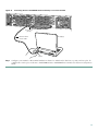
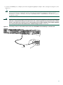
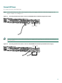
Connect a Console Terminal
Use the console terminal for local administrative access to the universal gateway. You can connect a terminal only to the console
port. You can use the auxiliary port to connect a terminal or a modem for remote access to the universal gateway.
To connect a terminal (an ASCII terminal or a PC running terminal emulation software) to the console port on a
Cisco AS5350XM or Cisco AS5400XM universal gateway, follow this procedure.
Step 1
Connect the terminal to the console port by using an RJ-45 rollover cable and an RJ-45-to-DB-25 or RJ-45-to-DB-9
adapter. (See Figure 18 and Figure 19.) The adapters provided are labeled TERMINAL. The adapters and the rollover
cable are included in the accessory kit that ships with the universal gateway.
Figure 18
Connecting the Cisco AS5350XM Universal Gateway to a Console Terminal
35676
Console port
(RJ-45)
RJ-45-to-RJ-45
rollover cable
PC (laptop)
RJ-45
16
Connecting the Cisco AS5400XM Universal Gateway to a Console Terminal
30845
Figure 19
Console port
(RJ-45)
PC (laptop)
RJ-45-to-RJ-45
rollover cable
RJ-45
Step 2
Configure your terminal or PC terminal emulation software for 9600 baud, 8 data bits, no parity, and 1 stop bit. To
configure the console port, see the Cisco AS5350XM and Cisco AS5400XM Universal Gateways Software Configuration
Guide.
17
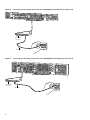
Connect to an Ethernet Network
Connect the universal gateway to an Ethernet network by using a straight-through RJ-45-to-RJ-45 Ethernet cable to connect
the Gigabit Ethernet port to an Ethernet hub or Gigabit Ethernet switch. (See Figure 20 and Figure 21.)
Connecting the Cisco AS5350XM Universal Gateway to an Ethernet Hub
2
1
8
122115
Figure 20
7
1
3
1
GE1 10/100/1000BASE-T port
2
Ethernet hub
3
Straight-through Ethernet cable
Connecting the Cisco AS5400XM Universal Gateway to an Ethernet Hub
2
1
8
7
1
3
1
GE1 10/100/1000BASE-T port
2
Ethernet hub
3
Straight-through Ethernet cable
18
122115
Figure 21
Connect to a WAN
Warning
The telecommunications lines must be disconnected 1) before unplugging the main power connector and/or 2)
while the housing is open. Statement 89
Warning
Hazardous network voltages are present in WAN ports regardless of whether power to the unit is OFF or ON. To
avoid electric shock, use caution when working near WAN ports. When detaching cables, detach the end away
from the unit first. Statement 1026
Warning
To reduce the risk of fire, use only No. 26 AWG or larger telecommunication line cord. Statement 1023
Warning
The ISDN connection is regarded as a source of voltage that should be inaccessible to user contact. Do not attempt
to tamper with or open any public telephone operator (PTO)-provided equipment or connection hardware. Any
hardwired connection (other than by a nonremovable, connect-one-time-only plug) must be made only by PTO staff
or suitably trained engineers. Statement 23
Warning
To avoid electric shock, do not connect safety extra-low voltage (SELV) circuits to telephone-network voltage
(TNV) circuits. LAN ports contain SELV circuits, and WAN ports contain TNV circuits. Some LAN and WAN ports
both use RJ-45 connectors. Use caution when connecting cables. Statement 1021
Warning
Incorrect connection of this or connected equipment to a general purpose outlet could result in a hazardous
situation. Statement 87
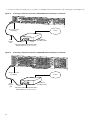
You can connect the Cisco AS5350XM and Cisco AS5400XM universal gateways to a WAN in the following ways:
• Connect each T1/PRI port to an RJ-45 jack with a straight-through RJ-45-to-RJ-45 cable. (See Figure 22, Figure 23, and
Figure 24.)
Connecting a 2-Port or 4-Port Feature Card on the Cisco AS5350XM Universal Gateway to an RJ-45 Jack
Straight-through
RJ-45-to-RJ-45 cable
RJ-45 jack
35672
Figure 22
19
Connecting an 8-Port Feature Card on the Cisco AS5350XM Universal Gateway to an RJ-45 Jack
6
7
P
P
4
5
P
P
2
3
P
P
0
P
P
1
56057
Figure 23
T1/E1 8 PRI
connector
Straight-through
RJ-45-to-RJ-45 cable
Connecting an 8-Port Feature Card on the Cisco AS5400XM Universal Gateway to an RJ-45 Jack
7
6
P
P
4
5
P
P
2
3
P
P
1
P
P
0
30848
Figure 24
RJ-45 jack
T1/E1 8 PRI
connector
Straight-through
RJ-45-to-RJ-45 cable
Note
20
RJ-45 jack
For other T1 cabling options, see the card installation guide for the Cisco AS5350XM and Cisco AS5400XM universal
gateways. You can access this document at Technical Support & Documentation > Product Support > Universal
Gateways and Access Servers > Cisco AS5300 or Cisco AS5400 Series Universal Gateways > Install and Upgrade
Guides.
• Connect each E1/PRI port to an RJ-45 jack with a straight-through RJ-45-to-RJ-45 cable. (See Figure 25, Figure 26, and
Figure 27.)
Note
If you choose a port with 75-ohm input impedance, use an RJ-45-to-75-ohm coaxial cable adapter and plug it into
that port. Use software commands to choose a particular port and the line termination on that port. For
information on software commands, see the Cisco AS5350XM and Cisco AS5400XM Universal Gateways Software
Configuration Guide.
The E1 interface card may only be installed in an ACA-permitted customer equipment or a Data Terminal Equipment
(DTE) that is exempted from ACA’s permit requirements. The customer equipment must only be housed in a cabinet
that has screw-down lids to stop user access to overvoltages on the customer equipment. The customer equipment
has circuitry that may have telecommunications network voltages on them. Statement 90
Figure 25
Connecting a 2-Port or 4-Port Feature Card on the Cisco AS5350XM Universal Gateway to an RJ-45 Jack
35673
Warning
RJ-45 jack
E1 cable
21
Connecting an 8-Port Feature Card on the Cisco AS5350XM Universal Gateway to an RJ-45 Jack
6
7
P
P
4
5
P
P
2
3
P
P
1
P
P
0
56058
Figure 26
T1/E1 8 PRI
connector
E1 cable
Connecting an 8-Port Feature Card on the Cisco AS5400XM Universal Gateway to an RJ-45 Jack
6
7
P
P
4
5
P
P
2
3
P
P
0
P
P
1
30847
Figure 27
RJ-45 jack
T1/E1 8 PRI
connector
E1 cable
RJ-45 jack
22
• Connect each CT3 feature card to a T3 CSU/DSU with two 75-ohm BNC cables. (See Figure 28 and Figure 29.)
Connecting a Channelized T3 Feature Card on the Cisco AS5350XM Universal Gateway to a T3 CSU/DSU
62177
Figure 28
T3 DFC
T3 cables
T3 CSU/DSU
BNC connectors
Connecting a Channelized T3 Feature Card on the Cisco AS5400XM Universal Gateway to a T3 CSU/DSU
62178
Figure 29
T3 DFC
T3 cables
T3 CSU/DSU
BNC connectors
23
• Connect a synchronous serial port to a modem or a CSU/DSU with a serial transition cable. (See Figure 30 and Figure 31.)
Connecting a Serial Port on the Cisco AS5350XM Universal Gateway to a CSU/DSU
35675
Figure 30
Synchronous serial
port (DB-26)
Internet
CSU/DSU or
other DCE or DTE
Serial
transition
cable
EIA/TIA-232, EIA/TIA-449, EIA/TIA-530A,
EIA/TIA-530, V.35, or X.21 connector
Connecting a Serial Port on the Cisco AS5400XM Universal Gateway to a CSU/DSU
30846
Figure 31
Synchronous serial
port (DB-26)
CSU/DSU or
other DCE or DTE
Serial
transition
cable
EIA/TIA-232, EIA/TIA-449, EIA/TIA-530A,
EIA/TIA-530, V.35, or X.21 connector
24
Internet
• Use a coaxial cable to connect a timing signal generator (TSG) to the building integrated timing supply (BITS) port. The
BITS port is used for external clocking. (See Figure 32.)
Connecting the Cisco AS5350XM and Cisco AS5400XM Universal Gateways to a TSG
35841
Figure 32
To timing signal
generator
Coaxial cable
BITS port
connector
• Use a copper wire cable to connect to the alarm port.
Warning
The plug-socket combination must be accessible at all times, because it serves as the main disconnecting device.
Statement 1019
Warning
Incorrect connection of this or connected equipment to a general purpose outlet could result in a hazardous
situation. Statement 87
To connect an alarm device to the alarm port, follow these steps.
Note
The alarm connector is a 3-wire connector that plugs into a receptacle on the back of the chassis. The connector is
provided in the accessory kit that ships with the universal gateway.
Step 1
Insert the 3-pin alarm port connector (included in the accessory kit) into the alarm port terminal block.
Step 2
Strip a minimum of 1/4 in. (0.625 cm) off the wire insulation to connect the stranded wires to the alarm connector. The
maximum insulation strip length is 0.31 in. (0.78 cm).
Note
Step 3
Caution
Use stranded number 12 or number 14 AWG copper wires to connect an alarm device to the alarm port connector.
Secure the wires to the alarm connector with the screws on the connector. (See Figure 33 and Figure 34.)
The maximum tightening torque on the screws is 7 in.-lb (0.79 N-m).
25
Figure 33
Connecting an Alarm Device to the Cisco AS5350XM Universal Gateway
To alarm device
Cable ties
Figure 34
#1
#3
#2
35967
Alarm port
connector
Connecting an Alarm Device to the Cisco AS5400XM Universal Gateway
Cable ties
#1
#3
#2
35145
Alarm port
connector
Step 4
Attach two cable ties to the chassis, and connect the wires to the cable ties.
Step 5
Attach the alarm wires to the alarm device. Table 4 describes the alarm pinouts.
Table 4
Alarm Pinouts
Pin1
Description
1
Normally open
2
Pole
3
Normally closed
1. The pins are numbered from left to right (facing the back of
the chassis), starting with pin 1.
26
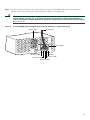
Connect AC Power
To connect AC power, follow these steps:
Step 1
Connect the black power cable to the receptacle on the power supply at the back of the universal gateway. (See
Figure 35, Figure 36, and Figure 37.)
Connecting the AC Power Cable to the Cisco AS5350XM Universal Gateway Single Power Supply
35678
Figure 35
Power switch
If you are using the Cisco AS5350XM redundant power supply, use the special power cable that came with your
universal gateway.
Figure 36
Connecting the AC Power Cables to the Cisco AS5350XM Universal Gateway Redundant Power Supply
Power switch
82079
Note
Power cables
27
Figure 37
Connecting the AC Power Cables to the Cisco AS5400XM Universal Gateway
30851
Power switch
Step 2
Connect the other end of the power cable to the electrical outlet.
Step 3
If your universal gateway has a redundant power supply installed, repeat Step 1 and Step 2 for the second power supply.
Connect DC Power
Warning
A readily accessible two-poled disconnect device must be incorporated in the fixed wiring. Statement 1022
Warning
This product relies on the building’s installation for short-circuit (overcurrent) protection. Ensure that a UL Listed
and Certified fuse or circuit breaker no larger than 60 VDC, 15 A is used on all current-carrying conductors.
Statement 96
If you ordered the universal gateway with a DC-input power supply, follow the directions in this section for proper wiring.
Caution
Note
In a DC power supply installation, do not connect the 48 VDC Return wire to chassis ground at the universal
gateway. A single-point ground is recommended at the power distribution rack.
This product is intended for installation in restricted access areas and is approved for connection using number 12 or
number 14 AWG copper conductors only. The installation must comply with all applicable codes.
To connect DC power, follow these steps:
Step 1
Warning
28
Remove power from the DC circuit.
Before connecting or disconnecting ground or power wires to the chassis, ensure that power is removed from the
DC circuit. To ensure that all power is OFF, locate the circuit breaker on the panel board that services the DC
circuit, switch the circuit breaker to the OFF position, and tape the switch handle of the circuit breaker in the OFF
position. Statement 140
Step 2
Note the orientation of the DC power supply. The power supply cord should have three wires: 48 VDC Return,
–48 VDC, and a safety ground (green wire). (See Figure 38, Figure 39, and Figure 40.)
Warning
The illustration shows the DC power supply terminal block. Wire the DC power supply using the appropriate lugs
at the wiring end, or with no lugs, as illustrated. The proper wiring sequence is ground to ground, positive to
positive, and negative to negative. Note that the ground wire should always be connected first and disconnected
last. Statement 197
Figure 38
Cisco AS5350XM Universal Gateway DC Power Supply Connections—Single Power Supply
Power switch
To DC source
56022
DC connector
Source A - NEG
Ground
Source B - RTN
Source A - RTN
Source B - NEG
29
Figure 39
Cisco AS5350XM Universal Gateway DC Power Supply Connections—Redundant Power Supply
To DC source
DC connector
Power switch
82637
A- A+ B- B+
Ground
Source A - NEG
Source B - RTN
Source A - RTN
Source B - NEG
Figure 40
Cisco AS5400XM Universal Gateway DC Power Supply Connections
Mounting screws
Terminal block
J2
IN OK
LEDs
DC
OTF
On/off switch
IN OK
LEDs
DC
OTF
Terminal block
146407
J1
Mounting screw
Step 3
30
Strip 1/4 in. (0.625 cm) of insulation off the safety ground, the 48 VDC Return, and the –48 VDC input wires.
Note
Step 4
Install the safety grounds (green wire) in the terminal block ground connectors and tighten the locking screws. Ensure
that no bare wire is exposed.
Note
Step 5
Caution
If you are installing a redundant power supply in the Cisco AS5350XM universal gateway, you should attach
spade terminals of the appropriate size to the stripped ends of the ground and input wires.
For central office installations, we recommend using a green number 6 AWG copper ground wire with one end
connected to reliable earth ground. The other end of the wire should be crimped onto the double-hole lug
provided in the installation pack. The lug should be secured to the mating holes on either side of the chassis
with the two screws included in the accessory pack.
Insert the 48 VDC Return wires into the terminal block positive connectors (+) and tighten the locking screws. Ensure
that no bare wire is exposed.
Do not overtorque the terminal block contact screws. The recommended torque is 5 in.-lb (0.56 N-m).
Step 6
Insert the –48 VDC wires into the terminal block negative connectors (–) and tighten the locking screws. Ensure that
no bare wire is exposed.
Step 7
Make sure that the power supply wires are secured to cable strain-relief clamps with cable ties.
Warning
Step 8
After wiring the DC power supply, remove the tape from the circuit breaker switch handle and reinstate power by
moving the handle of the circuit breaker to the ON position. Statement 8
Power up the universal gateway. The internal power supply fan should power up.
6 Power Up the Universal Gateway
Note
The information in this document applies to the Cisco AS5350XM and Cisco AS5400XM universal gateways.
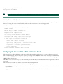
Checklist for Power Up
You are ready to power up the Cisco universal gateway if the following steps have been completed:
• The chassis is securely mounted.
• Power and interface cables are connected.
• Your PC terminal emulation program is configured for 9600 baud, 8 data bits, 1 stop bit, and no parity.
• You have selected passwords for access control.
• You have determined the IP addresses for the Ethernet and serial interfaces.
31
Power-Up Procedure
Perform this procedure to power up your Cisco universal gateway and verify that it goes through its initialization and self-test.
When this is finished, the Cisco universal gateway is ready to configure.
Note
To view the boot sequence through a terminal session, you must have a console connection to the Cisco universal
gateway before it powers up. To connect to the console, see the “Connect a Console Terminal” section on page 16.
Step 1
Move the power switch to the ON position. The system board OK LED should come on, and messages will begin to
appear in your terminal emulation program window.
Caution
Do not press any keys on the keyboard until the messages stop. Any keys pressed during this time are interpreted
as the first command typed when the messages stop, which might cause the universal gateway to power down and
start over. It takes a few minutes for the messages to stop.
Note
A Cisco AS5350XM or Cisco AS5400XM universal gateway with the maximum number of packet voice data
modules, version 2 (PVDM2) modules installed can take up to six minutes to boot from power-on to system ready.
Note
The messages displayed depend on the Cisco IOS software release and on the cards that are installed in your system.
The screen displays in this section are for reference only and might not exactly match the messages on your console.
The messages look similar to the following:
System Bootstrap, Version 12.3(12r)PI6, RELEASE SOFTWARE (fc1)
Technical Support: http://www.cisco.com/techsupport
Copyright (c) 2004 by cisco Systems, Inc.
AS5400XM platform with 524288 Kbytes of main memory
Self decompressing the image :
################################################################################################################
#################################################################################################### [OK]
Restricted Rights Legend
Use, duplication, or disclosure by the Government is
subject to restrictions as set forth in subparagraph
(c) of the Commercial Computer Software - Restricted
Rights clause at FAR sec. 52.227-19 and subparagraph
(c) (1) (ii) of the Rights in Technical Data and Computer
Software clause at DFARS sec. 252.227-7013.
cisco Systems, Inc.
170 West Tasman Drive
San Jose, California 95134-1706
Cisco IOS Software, 5400 Software (C5400-JS-M), Version 12.3(14)T,
Technical Support: http://www.cisco.com/techsupport
Copyright (c) 1986-2005 by Cisco Systems, Inc.
Compiled Sat 29-Jan-05 02:10 by yiyan
Image text-base: 0x60011068, data-base: 0x61F80000
RELEASE SOFTWARE (fc1)
Cisco AS5400XM (BCM) processor (revision 0x21) with 393215K/131072K bytes of memory.
Processor board ID JAB082904P4
SB-1 CPU at 750MHz, Implementation 1025, Rev 0.3, 256KB L2 Cache
32
Last reset from IOS reload
Manufacture Cookie Info:
EEPROM Version 0x4, Board ID 0x4BD,
Board Hardware Version 1.11, Item Number 800-6572289-01,
Board Revision 02, Serial Number JAB082904P4.
Processor 0x0, MAC Address badb.adba.d044
2 Gigabit Ethernet interfaces
6 Serial interfaces
648 terminal lines
1 Channelized T3 port
512K bytes of NVRAM.
125184K bytes of ATA External CompactFlash (Read/Write)
Press RETURN to get started!
Note
If the rommon 1> prompt appears, your system has booted in ROM monitor mode. For information on the ROM
monitor, see the universal gateway ROM monitor information in the Cisco IOS Configuration Fundamentals
Configuration Guide for your Cisco IOS software release.
7 Perform Initial Configuration
Note
The information in this document applies to the Cisco AS5350XM and Cisco AS5400XM universal gateways.
At this point you can continue, using the setup command facility, or you can configure the universal gateway manually using
the command-line interface (CLI).
• The following section describes the procedure for the setup command facility for the initial configuration.
• See the “Initial Configuration Using the CLI (Manual Configuration)” section on page 36 for information about manual
configuration using the CLI.
Initial Configuration Using the Setup Command Facility
This section shows how to prepare the system to perform basic communication functions through its Ethernet and WAN
interfaces.
Note
The messages displayed depend on the Cisco IOS software release and cards installed in your system. The screen
displays in this section are for reference only and might not exactly match the messages on your console.
Note
If you make a mistake while using the setup command facility, you can exit and run the facility again. Press Ctrl-C, and
type setup at the enable mode prompt (Router#).
Step 1
To proceed using the setup command facility, enter yes:
Would you like to enter the initial configuration dialog? [yes/no]: yes
At any point you may enter a question mark ‘?’ for help.
Use ctrl-c to abort configuration dialog at any prompt.
Default settings are in square brackets ‘[]’.
33
Step 2
When the following message appears, enter no to configure all interfaces:
Note
Note that, if you enter yes, your system will not be configured correctly.
Basic management setup configures only enough connectivity for management of the system. Extended setup will ask
you to configure each interface on the system.
Would you like to enter basic management setup? [yes/no]: no
Step 3
When the following message appears, press Return to see the current interface summary:
First, would you like to see the current interface summary? [yes]:
Any interface listed with OK? value “NO” does not have a valid configuration
Interface
Async1/00
Async1/01
.
.
.
GigbitEthernet0/0
GigbitEthernet0/1
Group-Async0
Serial0/0
Serial0/1
Step 4
IP-Address
unassigned
unassigned
unassigned
unassigned
unassigned
unassigned
unassigned
NO
NO
OK? Method Status
unset up
unset up
NO
NO
NO
NO
NO
unset up
unset up
unset up
unset up
unset up
Protocol
up
up
up
up
up
down
down
Enter a hostname for the gateway:
Configuring global parameters:
Enter host name [Router]: Gateway
Step 5
Enter an enable secret password. This password is encrypted (more secure) and cannot be seen when viewing the
configuration.
The enable secret is a password used to protect access to privileged EXEC and configuration modes. This
password, after entered, becomes encrypted in the configuration.
Enter enable secret: xxxx
Step 6
Enter an enable password that is different from the enable secret password. This password is not encrypted (less secure)
and can be seen when viewing the configuration.
The enable password is used when you do not specify an enable secret password, with some older software
versions, and some boot images.
Enter enable password: guessme
Step 7
Enter the virtual terminal password, which prevents unauthenticated access to the universal gateway through ports
other than the console port:
The virtual terminal password is used to protect access to the router over a network interface.
Enter virtual terminal password: guessagain
Step 8
Respond to the following prompts as appropriate for your network:
Configure System Management [yes/no] no
Configure SNMP Network Management? [yes]:
Community string [public]:
Configure LAT? [yes]: no
Configure AppleTalk? [no]:
Configure DECnet? [no]:
Configure IP? [no]: yes
Configure IGRP routing? [yes]:
Your IGRP autonomous system number [1]:
Configure CLNS? [no]:
Configure IPX? [no]:
34
Configure
Configure
Configure
Configure
Vines? [no]:
XNS? [no]:
Apollo? [no]:
bridging? [no]:
Async lines accept incoming modems calls. If you will have
users dialing in via modems, configure these lines.
Configure Async lines? [yes]:
Async line speed [115200]:
Will you be using the modems for inbound dialing? [yes]:
Would you like to put all async interfaces in a group and configure
them all at one time ? [yes]:
Allow dial-in users to choose a static IP address? [no]:
Configure for TCP header compression? [yes]:
Configure for routing updates on async links? [no]:
Enter the starting address of IP local pool? [X.X.X.X]: 10.1.2.1
Enter the ending address of IP local pool? [X.X.X.X]: 10.1.2.59
You can configure a test user to verify that
your dial-up service is working properly
Would you like to create a test user? [no]:
Will you be using the modems for outbound dialing? [no]:
Step 9
Enter the letter corresponding to the ISDN switch type that matches your telco switch type, or press Enter to accept the
default:
Do you want to configure ISDN switch type? [yes]:
The following ISDN switch types are available:
[a] primary-4ess
[b] primary-5ess
[c] primary-dms100
[d] primary-net5
[e] primary-ntt
[f] primary-ts014
Enter the switch type [b]:
Next, you will be prompted to configure controllers.
These controllers enable users to dial in via ISDN or analog modems.
Step 10 Enter yes to allow users to dial in using ISDN or analog modems:
Do you intend to allow users to dial in? [yes]:
There are 2 controllers on this access server. If you want to use
the full capacity of the access server configure all controllers.
Controller T3 0,1...etc in software corresponds to Port 0,1...etc
on the back of the access server.
PRI configuration can be configured to controllers all at once
based on your PRI controllers selection. Whereas CAS configuration
will be configured individually for each controller.
Step 11 Enter the number of controllers that you will be using for the PRI configuration, or press Enter to configure all
controllers:
Enter # of controllers, you will be using for PRI configuration [2]:
Configuring controller parameters:
Step 12 Press Enter for every slot, port, and channel:
Configuring controller t1 3/0:
Configuring PRI on this controller.
Configuring controller t1 3/1:
Configuring PRI on this controller.
35
Step 13 Enter yes to configure the Gigabit Ethernet 0/0 interface to connect the gateway to a LAN, and then respond to the
remaining questions to configure the Fast Ethernet port:
Do you want to configure GigabitEthernet0/0 interface? [no]: yes
Configure IP on this interface? [no]: yes
IP address for this interface: 172.22.50.10
Subnet mask for this interface [255.255.0.0] : 255.255.255.128
Class B network is 172.22.0.0, 25 subnet bits; mask is /25
Do you want to configure GigabitEthernet0/1
Note
interface? [no]:
The Gigabit Ethernet interfaces in the Cisco AS5350XM universal gateway can be configured as Fast Ethernet
interfaces in ROM monitor mode. For information on the ROM monitor, see the universal gateway ROM monitor
information in the Cisco IOS Configuration Fundamentals Configuration Guide for your Cisco IOS software
release.
Step 14 Configure your serial interfaces by responding to the following prompts:
Do you want to configure Serial0/0 interface? [no]: yes
Configure IP on this interface? [no]: yes
Configure IP unnumbered on this interface? [no]:
IP address for this interface interface: 172.22.50.11
Subnet mask for this interface: 255.255.0.0
Do you want to configure Serial0/1 interface? [yes]: no
Configuring interface Group-Async1:
Step 15 After you complete the configuration script, the setup script displays the configuration command script. Review your
new configuration and then make the appropriate selection below:
[0] Go to the IOS command prompt without saving this config.
[1] Return back to the setup without saving this config.
[2] Save this configuration to nvram and exit.
Enter your selection [2]:
Initial Configuration Using the CLI (Manual Configuration)
This section shows how to perform basic configuration using the command-line interface (CLI).
Step 1
To proceed with manual configuration using the CLI, enter no.
Would you like to enter the initial configuration dialog? [yes/no]: no
Step 2
To terminate autoinstall and continue with manual configuration, press Return:
Would you like to terminate autoinstall? [yes] Return
Step 3
To bring up the Router> prompt, press Return:
...
Router>
Step 4
Enter privileged EXEC mode.
Router> enable
Router#
Step 5
Enter global configuration mode. You are in global configuration mode when the prompt changes to Router(config)#.
Router# configure terminal
36
Enter configuration commands, one per line. End with CNTL/Z.
Router(config)#
Step 6
Change the name of the gateway to a meaningful name:
Router(config)# hostname Gateway
Gateway(config)#
Step 7
Create a secret password. This password provides access to privileged EXEC mode. Substitute your enable secret
password for guessme.
Gateway(config)# enable secret guessme
Step 8
Enable password encryption. When password encryption is enabled, the encrypted form of the password is displayed
when a show configuration command is entered. You cannot recover a lost encrypted password.
Gateway(config)# service password-encryption
Step 9
Configure debugging messages to include milliseconds in the date and time stamp:
Gateway(config)# service timestamps debug datetime msec
Step 10 Configure logging messages to include milliseconds in the date and time stamp:
Gateway(config)# service timestamps log datetime msec
Step 11 Enter line configuration mode to configure the console port. You are in line configuration mode when the prompt
changes to Gateway(config-line)#.
Gateway(config)# line con 0
Gateway(config-line)#
Step 12 Prevent the gateway’s EXEC facility from timing out if you do not type any information on the console screen for an
extended period:
Gateway(config-line)# exec-timeout 0 0
Step 13 Exit line configuration mode:
Gateway(config-line)# exit
Gateway(config)#
Step 14 Return to privileged EXEC mode:
Gateway(config)# Ctrl-Z
Gateway#
Step 15 Save the configuration:
Gateway# write memory
Building configuration ...
[OK]
Gateway#
Verifying the Hostname and Passwords
To verify that you configured the right hostname and passwords, follow these steps:
Step 1
Enter the show configuration command:
Gateway# show configuration
Using 1888 out of 512000 bytes
!
version XX.X
.
.
37
!
hostname Gateway
!
enable secret 5 $1$60L4$X2JYOwoDc0.kqa1loO/w8/
.
.
.
Step 2
Exit privileged EXEC mode and attempt to log in by using the new enable secret password. The show privilege
command shows the current security privilege level.
Gateway# exit
Gateway con0 is now available
Press RETURN to get started.
Gateway> enable
Password:
Gateway# show privilege
Current privilege level is 15
Gateway#
Configuring Local AAA Security
Configure authentication, authorization, and accounting (AAA) to perform login authentication by using the local username
database. The login keyword authenticates EXEC shell users. Additionally, configure PPP authentication to use the local
database if the session was not already authenticated by the login command.
AAA (called triple A) is the Cisco IOS security model used on all Cisco devices. AAA provides the primary framework through
which you set up access control on the Cisco AS5350XM or Cisco AS5400XM universal gateway.
The same authentication method is used on all interfaces. AAA is set up to use the local database configured on the gateway.
This local database is created with the username configuration commands.
To configure AAA, follow these steps:
Step 1
Enter global configuration mode. You are in global configuration mode when your prompt changes to
Gateway(config)#.
Gateway# configure terminal
Enter configuration commands, one per line. End with CNTL/Z.
Gateway(config)#
Step 2
Create a local login username database in global configuration mode. In this example, the administrator’s username is
admin. The remote client’s login username is Harry.
Gateway(config)# username admin password adminpasshere
Gateway(config)# username Harry password Harrypasshere
Step 3
Configure local AAA security in global configuration mode. You must enter the aaa new-model command before the
other two authentication commands.
Gateway(config)# aaa new-model
Gateway(config)# aaa authentication login default local
Gateway(config)# aaa authentication ppp default if-needed local
Step 4
Return to privileged EXEC mode:
Gateway(config)# Ctrl-Z
Gateway#
Step 5
38
Log in with your username and password.
Caution
After you have configured AAA security, all access will require a username and password. Make sure that your
login name and password are working before you exit or reboot. If you are unable to get back into your universal
gateway, see the password recovery instructions at the following URL:
http://www.cisco.com/warp/public/474/pswdrec_as5300.shtml
Gateway# login
User Access Verification
Username: admin
Password:
Gateway#
Tip
To save the gateway configuration, save it to NVRAM. See the “Saving Configuration Changes” section on page 60.
Note
For comprehensive information about how to implement a Cisco AAA-based security environment, see the relevant
documents at Technical Support & Documentation > Product Support > Cisco IOS Software > Cisco IOS Software
Release you are using > Configuration Guides.
Configuring Basic Dial Access
To commission a basic dial access service, use the procedure below to perform the following tasks:
• Create two loopback interfaces.
• Bring up the Gigabit Ethernet interface.
• Add an IP route to the default gateway.
Step 1
Enter global configuration mode. You are in global configuration mode when your prompt changes to
Gateway(config)#.
Gateway# configure terminal
Enter configuration commands, one per line. End with CNTL/Z.
Gateway(config)#
Step 2
Assign the IP addresses as in the following example, and create an IP route to the default gateway:
Gateway(config)# interface loopback 0
Gateway(config-if)# ip address 172.22.99.1 255.255.255.255
Gateway(config-if)# exit
Gateway(config)# interface loopback 1
Gateway(config-if)# ip address 172.22.90.1 255.255.255.0
Gateway(config-if)# exit
Gateway(config)# interface GigabitEthernet 0/0
Gateway(config-if)# ip address 172.28.186.55 255.255.255.240
Gateway(config-if)# no shutdown
Gateway(config-if)# exit
Gateway(config)# ip route 0.0.0.0 0.0.0.0 172.28.186.49
39
In this example:
• Interface loopback 0—Identifies the universal gateway with a unique and stable IP address. One unique IP address from a
common block of addresses is assigned to each device in the IP network. This technique makes security-filtering easy for
the Network Operations Center (NOC). One Class C subnet used for device identification can support 254 distinct devices
with unique loopback addresses.
• Interface loopback 1—Hosts a pool of IP addresses for the remote nodes. In this way, one route, instead of 254 routes, is
summarized and propagated to the backbone. Pick the IP address for loopback 1 from the range of addresses that you will
assign to the local address pool.
Step 3
Return to privileged EXEC mode:
Gateway(config)# Ctrl-Z
Gateway#
Step 4
Verify that the Gigabit Ethernet interface is up. Ping the default gateway to verify this.
Gateway# ping 172.28.186.49
Type escape sequence to abort.
Sending 5, 100-byte ICMP Echos to 172.28.186.49, timeout is 2 seconds:
.!!!!
Success rate is 80 percent (4/5), round-trip min/avg/max = 1/1/4 ms
To save the gateway configuration, save it to NVRAM. See the “Saving Configuration Changes” section on page 60.
Tip
Note
An 80 percent success rate is normal for the first time you ping an external device. The universal gateway does not
have an Address Resolution Protocol (ARP) entry for the external device. A 100 percent success rate is achieved
the next time you ping the device.
Configuring the Asynchronous Group Interface
This section shows how to configure asynchronous interfaces. Asynchronous group interfaces allow administrators to easily
configure a large number of asynchronous interfaces by allowing them to clone interfaces from one managed copy. This can also
reduce the number of lines in the configuration file, because each individual asynchronous interface configuration can be
replaced by at least one group-async interface. To assign the asynchronous interfaces to a group-async interface, first determine
the number of asynchronous lines that need to be aggregated. This can be determined from the running configuration.
Step 1
Enter the enable command and password to go to privileged EXEC mode. You are in privileged EXEC mode when the
prompt changes to Gateway#.
Gateway> enable
Password: password
Gateway#
Step 2
Enter global configuration mode. You are in global configuration mode when the prompt changes to
Gateway(config)#.
Gateway# configure terminal
Enter configuration commands, one per line. End with CNTL/Z.
Gateway(config)#
Step 3
Place all asynchronous interfaces in a single group, so that you configure the same parameters quickly on all interfaces
at one time:
Gateway(config)# interface group-async 1
Gateway(config-if)#
40
Step 4
Define the slot/port group range of the interface. The range that you specify depends on the number of asynchronous
interfaces you have on your gateway. If your gateway has 108 asynchronous interfaces, you can specify group-range
1/1 1/107.
Gateway(config-if)# group-range slot/port slot/port
Building configuration...
Gateway(config-if)#
Step 5
Return to privileged EXEC mode:
Gateway(config-if)# Ctrl-Z
Gateway#
Tip
To save the gateway configuration, save it to NVRAM. See the “Saving Configuration Changes” section on page 60.
Verifying the Group Interface Configuration
To verify your group interface configuration, enter the show interface async command in privileged EXEC mode:
Gateway# show interface async 4/0
Async4/00 is down, line protocol is down
modem(slot/port)=4/0, state=IDLE
dsx1(slot/unit/channel)=NONE, status=VDEV_STATUS_UNLOCKED
Hardware is Async Serial
MTU 1500 bytes, BW 115 Kbit, DLY 100000 usec,
reliability 255/255, txload 1/255, rxload 1/255
Encapsulation SLIP, loopback not set
DTR is pulsed for 5 seconds on reset
Last input never, output never, output hang never
Last clearing of "show interface" counters never
Input queue: 0/10/0/0 (size/max/drops/flushes); Total output drops: 0
Queueing strategy: weighted fair
Output queue: 0/1000/64/0 (size/max total/threshold/drops)
Conversations 0/1/32 (active/max active/max total)
Reserved Conversations 0/0 (allocated/max allocated)
Available Bandwidth 86 kilobits/sec
5 minute input rate 0 bits/sec, 0 packets/sec
5 minute output rate 0 bits/sec, 0 packets/sec
0 packets input, 0 bytes, 0 no buffer
Received 0 broadcasts, 0 runts, 0 giants, 0 throttles
0 input errors, 0 CRC, 0 frame, 0 overrun, 0 ignored, 0 abort
0 packets output, 0 bytes, 0 underruns
0 output errors, 0 collisions, 0 interface resets
0 output buffer failures, 0 output buffers swapped out
0 carrier transitions
If you are having trouble, check for errors as well as local and remote addresses. Enter the show async status command in
privileged EXEC mode:
Gateway# show async status
Async protocol statistics:
Int
1/00
1/01
1/02
1/03
1/04
1/05
Local
42.1.1.1
192.168.10.100
192.168.10.100
192.168.10.100
192.168.10.100
192.168.10.100
Remote
None
None
None
None
None
None
Qd
0
0
0
0
0
0
InPack
0
0
0
0
0
0
OutPac
0
0
0
0
0
0
Inerr
0
0
0
0
0
0
Drops
0
0
0
0
0
0
MTU
1500
1500
1500
1500
1500
1500
41
.
Rcvd: 25762 packets, 1052214 bytes
0 format errors, 891 checksum errors, 0 overrun
Sent: 8891 packets, 222264 bytes, 0 dropped
Configuring a T1 or E1 Feature Card
This section shows how to configure a T1 or E1 feature card. On a Cisco AS5350XM or Cisco AS5400XM universal gateway,
you can allocate the available channels for channelized T1 and E1 in the following ways:
• You can configure all channels to support ISDN PRI.
• If you are not running ISDN PRI, you can configure all channels to support robbed-bit signaling (also known as
channel-associated signaling).
• You can configure all channels in a single channel group.
• You can configure mix and match channels supporting ISDN PRI, channel grouping, and channel-associated signaling
(CAS).
• You can configure mix and match channels supporting ISDN PRI, channel grouping, and robbed-bit signaling across the
same T1 line. For example, on the same channelized T1 you can use the pri-group timeslots 1-10,24 command,
channel-group 11 timeslots 11-16 command, and ds0-group 17 timeslots 17-23 type e&m-fgb command. This is an unusual
configuration because it requires you to align the correct range of time slots on both ends of the connection.
Note
For configuration information about leased-line or nondial use, see the Cisco IOS Dial Technologies Configuration
Guide, available online. You can access this document at Technical Support & Documentation > Product Support >
Cisco IOS Software > Cisco IOS Software Release you are using > Configuration Guides.
Note
The T1 and E1 controller numbering convention is slot/port in CLI commands. Feature card slot numbering starts from
the motherboard and works up from left to right. Slot 0 is reserved for the motherboard. The CT1/E1 feature card slots
are numbered sequentially from 1 to 7. Port numbering is from 0 to 7.
Step 1
Use the enable command and password to enter privileged EXEC mode. You are in privileged EXEC mode when the
prompt changes to Gateway#.
Gateway> enable
Password: password
Gateway#
Step 2
Enter global configuration mode. You are in global configuration mode when the prompt changes to Gateway(config)#.
Gateway# configure terminal
Enter configuration commands, one per line. End with CNTL/Z.
Gateway(config)#
Step 3
Enter controller configuration mode to configure your controller slot and port. Slot values range from 1 to 7. Port
values range from 0 to 7 for T1 and E1.
Gateway(config)# controller [t1 | e1] slot/port
Gateway(config-controller)#
Step 4
Enter the telco framing type.
• For the CT1 controller, enter either esf or sf:
Gateway(config-controller)# framing esf
• For the CE1 controller, enter crc4:
Gateway(config-controller)# framing crc4
42
Step 5
Define the line code.
• For the CT1 controller, use binary 8 zero substitution (B8ZS):
Gateway(config-controller)# linecode b8zs
• For the CE1 controller, use high-density bipolar 3 (HDB3):
Gateway(config-controller)# linecode hdb3
Step 6
Return to privileged EXEC mode:
Gateway(config-controller)# Ctrl-Z
Gateway#
Tip
To save the gateway configuration, save it to NVRAM. See the “Saving Configuration Changes” section on page 60.
Verifying Channelized T1 or E1 Controller Operation
To verify that your controller is up and running and that no alarms have been reported, enter the show controller command and
specify the controller type, slot, and port numbers:
Gateway# show controller t1 1/7
T1 1/7 is up.
No alarms detected.
Framing is ESF, Line Code is B8ZS, Clock Source is Line Primary.
Version info of slot 2: HW: 2, Firmware: 14, NEAT PLD: 13, NR Bus PLD: 19
Data in current interval (476 seconds elapsed):
0 Line Code Violations, 0 Path Code Violations
0 Slip Secs, 0 Fr Loss Secs, 0 Line Err Secs, 0 Degraded Mins
0 Errored Secs, 0 Bursty Err Secs, 0 Severely Err Secs, 0 Unavail Secs
Total Data (last 24 hours)
0 Line Code Violations, 0 Path Code Violations,
0 Slip Secs, 0 Fr Loss Secs, 0 Line Err Secs, 0 Degraded Mins,
0 Errored Secs, 0 Bursty Err Secs, 0 Severely Err Secs, 0 Unavail Secs
If you are having trouble, consider these possibilities:
• First check that the configuration is correct. The framing type and line code should match what the service provider has
specified. Then check channel group and PRI-group configurations, especially to verify that the time slots and speeds are
what the service provider has specified. At this point, the show controller t1 or show controller e1 command should be used
to check for T1 or E1 errors. Use the command several times to determine whether error counters are increasing, or whether
the line status is continually changing. If error counters are increasing or line status is changing, work with your service
provider to resolve the issue.
• Another common reason for failure is the dial-tdm-clock priority setting. The default setting is a free-running clock that
causes clock slip problems if it is not set properly.
Configuring a Channelized T3 Feature Card
The CT3 feature card offers 28 individual T1 channels (bundled as a T3 line) for serial transmission of voice and data. The CT3
link supports the maintenance data link channel in C-bit parity mode and also in payload and network loopbacks. The T1
interfaces multiplexed in the CT3 link support facilities data link (FDL) in extended super frame (ESF) framing.
Note
The CT3 controller numbering convention is slot/port in CLI commands. Feature card slot numbering starts from the
motherboard and works up from left to right. Slot 0 is reserved for the motherboard. The feature card slots are
numbered sequentially from 1 to 7. The port number value is always 0. Under the CT3 controller, the CT1 controller
numbering convention is slot/port:channel in CLI commands. Port numbering values range from 1 to 28.
43
Step 1
Use the enable command and password to enter privileged EXEC mode. You are in privileged EXEC mode when the
prompt changes to Gateway#.
Gateway> enable
Password: password
Gateway#
Step 2
Enter global configuration mode. You are in global configuration mode when the prompt changes to Gateway(config)#.
Gateway# configure terminal
Enter configuration commands, one per line. End with CNTL/Z.
Gateway(config)#
Step 3
Enter controller configuration mode to configure your T3 controller for slot 1 port 0. Slot values range from 1 to 7.
The port number is always 0.
Gateway(config)# controller t3 1/0
Gateway(config-controller)#
Step 4
Enter the telco framing type, either c-bit or m23:
Gateway(config-controller)# framing c-bit
Step 5
Enter your clock source, either internal or line:
Gateway(config-controller)# clock source line
Step 6
Enter your cable length. Values range in feet from 0 to 450.
Gateway(config-controller)# cablelength 450
Step 7
Configure your T1 controllers. The range is 1 to 28.
• To configure all 28 T1 controllers at once, enter:
Gateway(config-controller)# t1 1-28 controller
• To omit specified T1 controllers while configuring others, specify them as needed. In this instance, T1 controllers
11–14, 21, 22, and 24–28 are not configured.
Gateway(config-controller)# t1 1-10,15-20,23 controller
Step 8
Return to privileged EXEC mode:
Gateway(config-controller)# Ctrl-Z
Gateway#
Tip
To save the gateway configuration, save it to NVRAM. See the “Saving Configuration Changes” section on page 60.
Verifying Channelized T3 Controller Operation
To verify that your controller is up and running and that no alarms have been reported, enter the show controller command and
specify the controller type, slot, and port numbers:
Gateway# show controller t3 1/0
T3 1/0 is up.
Applique type is Channelized T3
No alarms detected.
MDL transmission is disabled
FEAC code received:No code is being received
Framing is C-BIT Parity, Line Code is B3ZS, Clock Source is Internal
Data in current interval (270 seconds elapsed):
0 Line Code Violations, 0 P-bit Coding Violation
44
0 C-bit Coding Violation, 0 P-bit Err Secs
0 P-bit Severely Err Secs, 0 Severely Err Framing Secs
0 Unavailable Secs, 0 Line Errored Secs
0 C-bit Errored Secs, 0 C-bit Severely Errored Secs
Total Data (last 32 15 minute intervals):
0 Line Code Violations, 0 P-bit Coding Violation,
0 C-bit Coding Violation, 0 P-bit Err Secs,
0 P-bit Severely Err Secs, 0 Severely Err Framing Secs,
0 Unavailable Secs, 0 Line Errored Secs,
0 C-bit Errored Secs, 0 C-bit Severely Errored Secs
Configuring ISDN PRI
Channelized T1 ISDN PRI offers 23 B channels and 1 D channel. Channelized E1 ISDN PRI offers 30 B channels and
1 D channel. Channel 24 is the D channel for T1, and channel 16 is the D channel for E1. ISDN provides out-of-band signaling
using the D channel for signaling and the B channels for user data.
For a complete description of the commands mentioned in this section, see the Cisco IOS Dial Technologies Configuration
Guide, which is available online. You can access this document at Technical Support & Documentation > Product Support >
Cisco IOS Software > Cisco IOS Software Release you are using > Configuration Guides.
Request PRI Line and Switch Configuration from a Telco Service Provider
Before configuring ISDN PRI on your Cisco universal gateway, you must order a correctly provisioned ISDN PRI line from your
telecommunications service provider.
This process varies from provider to provider both nationwide and internationally. However, some general guidelines apply:
• Determine whether the outgoing B channel calls are made in ascending or descending order. The Cisco IOS software default
is descending order; however, if the switch from the service provider is configured for outgoing calls made in ascending
order, the universal gateway can be configured to match the switch configuration of the service provider.
• Ask for delivery of calling line identification. Providers sometimes call this CLI or automatic number identification (ANI).
• If the gateway will be attached to an ISDN bus (to which other ISDN devices might be attached), ask for point-to-multipoint
service (subaddressing is required) and a voice-and-data line.
Configure ISDN PRI by following these steps:
Step 1
Use the enable command and password to enter privileged EXEC mode. You are in privileged EXEC mode when the
prompt changes to Gateway#.
Gateway> enable
Password: password
Gateway#
Step 2
Enter global configuration mode. You are in global configuration mode when the prompt changes to Gateway(config)#.
Gateway# configure terminal
Enter configuration commands, one per line. End with CNTL/Z.
Gateway(config)#
Step 3
Select a service provider switch type (see Table 5) that matches your service provider switch:
Gateway(config)# isdn switch-type switch-type
45
Table 5
ISDN Switch Types
Area
Keyword
Switch Type
Australia
primary-ts014
Australia PRI switches
Europe
primary-net5
European, New Zealand, and Asia ISDN PRI
switches (covers the Euro-ISDN E-DSS1
signaling system and is European
Telecommunication Standards Institute or
ETSI-compliant)
Japan
primary-ntt
Japanese ISDN PRI switches
None
none
No switch defined
North America
primary-4ess
AT&T 4ESS switch type for the United States
primary-5ess
AT&T 5ESS switch type for the United States
primary-dms100
NT DMS-100 switch type for the United States
primary-ni
National ISDN switch type
Step 4
Specify the T1, E1, or CT3 controller that you want to configure.
Note
The T1/E1 controller numbering convention is slot/port in CLI commands. Feature card slot numbering starts
from the motherboard and works up from left to right. Slot 0 is reserved for the motherboard. The feature card
slots are numbered sequentially from 1 to 3 for the Cisco AS5350XM universal gateway and from 1 to 7 for
the Cisco AS5400XM universal gateway. Port numbering is from 0 to 7, depending on the WAN feature card
installed.
The CT3 controller numbering convention is slot/port in CLI commands. Feature card slot numbering starts
from the motherboard and works up from left to right. Slot 0 is reserved for the motherboard. The feature card
slots are numbered sequentially from 1 to 3 for the Cisco AS5350XM universal gateway and from 1 to 7 for
the Cisco AS5400XM universal gateway. The port number value is always 0. Under the CT3, the T1 controller
numbering convention is slot/port:channel in CLI commands. Channel values range from 1 to 28. For
illustrations of slot locations, see the “Slot Numbering” section on page 62.
Gateway(config)# controller t1 1/0
or
Gateway(config)# controller t3 7/0:16
or
Gateway(config)# controller e1 1/0
Note
Step 5
When you configure the CT1or CE1 controller, a corresponding D-channel serial interface is created
automatically.
Specify the PRI channels:
Gateway(config-controller)# pri-group [timeslots range]
Note
46
For CT1 ISDN PRI—If you do not specify the time slots, the specified controller is configured for 23 B channels
and 1 D channel. B channel numbers range from 1 to 23; channel 24 is the D channel for T1. Corresponding
serial interface numbers range from 0 to 23. In commands, the D channel is interface serial slot/port:23—for
example, interface serial 1/0:23.
Note
Step 6
For CE1 ISDN PRI—If you do not specify the time slots, the specified controller is configured for 30 B channels
and 1 D channel. B channel numbers range from 1 to 31; channel 16 is the D channel for E1. Corresponding
serial interface numbers range from 0 to 30. In commands, the D channel is interface serial slot/port:15—for
example, interface serial 1/0:15.
Return to privileged EXEC mode:
Gateway(config-controller)# Ctrl-Z
Gateway#
Tip
To save the gateway configuration, save it to NVRAM. See the “Saving Configuration Changes” section on page 60.
Verifying Interface Configuration
To verify that you have configured the interfaces correctly, enter these commands:
• Enter the show controller t3 command and specify the slot and port numbers. Verify that the controller is up and that you
do not have excessive errors; otherwise, your controller might go down frequently. This could indicate switch problems.
Gateway# show controller t3 1/0
T3 1/0 is up.
Applique type is Channelized T3
No alarms detected.
MDL transmission is disabled
FEAC code received:No code is being received
Framing is C-BIT Parity, Line Code is B3ZS, Clock Source is Internal
Data in current interval (270 seconds elapsed):
0 Line Code Violations, 0 P-bit Coding Violation
0 C-bit Coding Violation, 0 P-bit Err Secs
0 P-bit Severely Err Secs, 0 Severely Err Framing Secs
0 Unavailable Secs, 0 Line Errored Secs
0 C-bit Errored Secs, 0 C-bit Severely Errored Secs
Total Data (last 32 15 minute intervals):
0 Line Code Violations, 0 P-bit Coding Violation,
0 C-bit Coding Violation, 0 P-bit Err Secs,
0 P-bit Severely Err Secs, 0 Severely Err Framing Secs,
0 Unavailable Secs, 0 Line Errored Secs,
0 C-bit Errored Secs, 0 C-bit Severely Errored Secs
• Enter the show controller t1 command and specify the slot and port numbers:
Gateway# show controller t1 1/0
T1 1/0 is up.
Applique type is Channelized T1
Cablelength is long gain36 0db
No alarms detected.
alarm-trigger is not set
Version info of slot 1: HW:768, PLD Rev:4
Framer Version:0x8
Manufacture Cookie Info:
EEPROM Type 0x0001, EEPROM Version 0x01, Board ID 0x041,
Board Hardware Version 3.0, Item Number 73-4089-03,
Board Revision 05, Serial Number JAB99432626,
PLD/ISP Version 0.1, Manufacture Date 11-Nov-1999.
Framing is ESF, Line Code is B8ZS, Clock Source is Line.
Data in current interval (264 seconds elapsed):
3 Line Code Violations, 1 Path Code Violations
47
5 Slip Secs, 0 Fr Loss Secs, 1 Line Err Secs, 1 Degraded Mins
5 Errored Secs, 0 Bursty Err Secs, 0 Severely Err Secs, 0 Unavail Secs
• Enter the show isdn status command to view layer status information:
Gateway# show isdn status
Global ISDN Switchtype = primary-5ess
ISDN Serial1/0:1:23 interface
dsl 0, interface ISDN Switchtype = primary-5ess
Layer 1 Status:
ACTIVE
Layer 2 Status:
TEI = 0, Ces = 1, SAPI = 0, State = MULTIPLE_FRAME_ESTABLISHED
Layer 3 Status:
0 Active Layer 3 Call(s)
Activated dsl 0 CCBs = 0
The Free Channel Mask: 0x807FFFFF
• Enter the show isdn service command to monitor ISDN channels and service:
Gateway# show isdn service
PRI Channel Statistics:
ISDN Se3/0:23, Channel [1-24]
Configured Isdn Interface (dsl) 0
Channel State (0=Idle 1=Proposed 2=Busy 3=Reserved 4=Restart 5=Maint_Pend)
Channel : 1 2 3 4 5 6 7 8 9 0 1 2 3 4 5 6 7 8 9 0 1 2 3 4
State
: 0 0 0 0 0 0 0 0 0 0 0 0 0 0 0 0 0 0 0 0 0 0 0 3
Service State (0=Inservice 1=Maint 2=Outofservice)
Channel : 1 2 3 4 5 6 7 8 9 0 1 2 3 4 5 6 7 8 9 0 1 2 3 4
State
: 0 0 0 0 0 0 0 0 0 0 0 0 0 0 0 0 0 0 0 0 0 0 0 2
.
.
.
Note
Your Cisco AS5350XM or Cisco AS5400XM universal gateway supports a total of 248 ISDN channels per ingress
feature card. If you are configuring individual T1 channels of your CT3 interface for backup links or serial backhaul
connections, the T1 channels must be configured into channel groups. Each channel group uses 24 time slots or
channels. For example, to configure six T1 channels (6 x 24), 144 ISDN channels are in use, leaving the remaining 104
(248–144) channels for ISDN use.
In the following show running-config example, five T1 channels are configured into channel groups:
Gateway# show running-config
Building configuration...
Current configuration:
!
! Last configuration change at 15:49:30 UTC Mon Apr 3 2000 by admin
! NVRAM config last updated at 01:35:05 UTC Fri Mar 17 2000 by admin
!
version 12.0
service timestamps debug datetime msec localtime show-timezone
service timestamps log datetime msec localtime show-timezone
service password-encryption
!
---text omitted--!
controller T3 1/0
framing m23
clock source line
t1 1-28 controller
!
controller T1 1/0:11
48
framing esf
channel-group 20 timeslots 1-24 speed 64
!
controller T1 1/0:12
framing esf
channel-group 20 timeslots
!
controller T1 1/0:13
framing esf
channel-group 20 timeslots
!
controller T1 1/0:14
framing esf
channel-group 20 timeslots
!
controller T1 1/0:15
framing esf
channel-group 20 timeslots
1-24 speed 64
1-24 speed 64
1-24 speed 64
1-24 speed 64
If you are having trouble, consider these possibilities:
• If the Layer 1 Status is “Deactivated,” make sure that the cable connection is not loose or disconnected. This status message
indicates a problem at the physical layer.
• There may be a problem with your telco, or the framing and line code types you entered may not match those of your telco.
A Layer 2 error indicates that the universal gateway cannot communicate with the telco. There is a problem at the data link
layer.
Configuring the D Channels for ISDN Signaling
The ISDN D channels carry the control and signaling information for your ISDN calls—for both circuit-switched data calls, and
analog modem calls.
The D channel notifies the central office switch to send the incoming call to particular time slots on the Cisco universal gateway.
Each one of the B channels carries data or voice. The D channel carries signaling for the B channels. The D channel identifies
whether the call is a circuit-switched digital call or an analog modem call. Analog modem calls are decoded and then sent off
to the onboard modems. Circuit-switched digital calls are directly relayed to the ISDN processor in the gateway.
When you configured your ISDN PRI on the CT1 or CE1 controller, you automatically created a serial interface that corresponds
to the PRI group time slots. This interface is a logical entity that is associated with the specific controller. After the serial
interface is created, you must configure the D channel serial interface that carries signaling. The configuration applies to all the
PRI B channels (time slots) for that PRI group.
Figure 41 shows the logical contents of an ISDN PRI interface used in a T1 network configuration. The logical contents include
23 B channels, 1 D channel, 24 time slots, and 24 virtual serial interfaces (total number of B channels + D channel).
49
Relationship of ISDN PRI Components for T1
Channel
type
Time slot
number
Virtual
serial
interface
number
B
B
B
B
•
•
•
•
•
B
B
B
D
1
2
3
4
•
•
•
•
•
21
22
23
24
S0:0
S0:1
S0:2
S0:3
•
•
•
•
•
S0:20
S0:21
S0:22
S0:23
Note
(data channel)
(data channel)
(data channel)
(data channel)
(data channel)
(data channel)
(data channel)
(signaling channel)
Logical
contents
of a PRI
interface
35765
Figure 41
When you configure your CT1 controller for a Non-Facility Associated Signaling (NFAS) backup D channel, a serial
interface is automatically created only when your primary D channel fails.
To configure ISDN signaling, follow these steps:
Step 1
Enter the enable command and password to go to privileged EXEC mode. You are in privileged EXEC mode when the
prompt changes to Gateway#.
Gateway> enable
Password: password
Gateway#
Step 2
Enter global configuration mode. You are in global configuration mode when the prompt changes to Gateway(config)#.
Gateway# configure terminal
Enter configuration commands, one per line. End with CNTL/Z.
Gateway(config)#
Step 3
Enter serial interface configuration mode. After the CT1 controller is configured, a corresponding D-channel serial
interface is automatically created. For example, serial interface 1/0:23 is the D channel for CT1 controller 1. You must
configure each serial interface to receive incoming signaling and send outgoing signaling.
Note
On a CE1 PRI line, the serial interface for the D channel is 1/0:15.
Gateway(config)# interface serial 1/0:23
Gateway(config-if)#
Step 4
Assign an IP address and subnet mask to the interface:
Gateway(config-if)# ip address 172.16.254.254 255.255.255.0
Step 5
Configure all incoming voice calls.
Note
This command has two possible keywords: data and modem. You must use the modem keyword to enable both
modem and voice calls. The modem keyword represents bearer capabilities of speech.
Gateway(config-if)# isdn incoming-voice modem
50
Step 6
Return to privileged EXEC mode:
Gateway(config-if)# ctrl-z
Gateway#
Tip
To save the gateway configuration, save it to NVRAM. See the “Saving Configuration Changes” section on page 60.
Verifying D Channel Configuration
To verify your D channel configuration, enter the show interface serial command and make sure that the line protocol is up and
that you are using the correct IP interface. Also, make sure that excessive errors are not being reported.
Gateway# show interface serial 1/0:23
Serial1/0:23 is up, line protocol is up (spoofing)
Hardware is DSX1
Internet address is 172.16.254.254/16
MTU 1500 bytes, BW 64 Kbit, DLY 20000 usec,
reliability 255/255, txload 1/255, rxload 1/255
Encapsulation PPP, loopback not set
Last input 00:00:03, output never, output hang never
Last clearing of "show interface" counters 00:00:01
Queueing strategy:fifo
Output queue 0/40, 0 drops; input queue 0/75, 0 drops
1 minute input rate 0 bits/sec, 0 packets/sec
1 minute output rate 0 bits/sec, 0 packets/sec
0 packets input, 0 bytes, 0 no buffer
Received 0 broadcasts, 0 runts, 0 giants, 0 throttles
0 input errors, 0 CRC, 0 frame, 0 overrun, 0 ignored, 0 abort
0 packets output, 0 bytes, 0 underruns
0 output errors, 0 collisions, 0 interface resets
0 output buffer failures, 0 output buffers swapped out
0 carrier transitions
Timeslot(s) Used:24, Transmitter delay is 0 flags
Configuring the Universal Port or Dial-Only Feature Cards
The universal port or dial-only feature cards support all modem standards and features. In contrast to the more traditional
line-to-modem mapping, lines are mapped to a system processing engine (SPE) that resides on the universal port and dial-only
feature card. Associated SPE firmware serves a function similar to that of modem code on a modem ISDN channel aggregation
(MICA) technologies modem.
One SPE provides services for six ports, with additional ports per SPE. Busyout and shutdown can be configured at the SPE or
port level.
The universal port and dial-only feature card performs the following functions:
• Converts pulse code modulation (PCM) bitstreams to digital packet data
• Forwards converted and packetized data to the main processor, which examines the data and forwards it to the backhaul
egress interface
• Supports all modem standards (such as V.34 and V.42bis) and features, including dial-in and dial-out
51
Note
For detailed information about the universal port and dial-only feature card CLI commands, see the Monitoring Voice
and Fax Services on the Cisco AS5350 and Cisco AS5400 Universal Gateway document, which is available online at
the following URL:
http://www.cisco.com/en/US/products/sw/iosswrel/ps1839/products_feature_guide09186a0080080e60.html
SPE Firmware
SPE firmware is automatically downloaded to universal port or dial-only feature cards from the Cisco AS5350XM or
Cisco AS5400XM universal gateway when you boot the system for the first time or when you insert a universal port or dial-only
feature card while the system is operating. When you insert feature cards while the system is operating, the Cisco IOS image
recognizes the cards and downloads the required firmware to the cards.
The SPE firmware image is bundled with the universal gateway Cisco IOS image. The SPE firmware image uses an autodetect
mechanism that enables the universal port and dial-only feature cards to service multiple call types. An SPE detects the call type
and automatically configures itself for that operation. The firmware is upgradable independent of Cisco IOS upgrades, and
different firmware versions can be configured to run on SPEs in the same feature card.
The universal port and dial-only feature cards support the modem standards and features listed in Table 6.
Table 6
Modem Standards and Supported Features
Feature
Description
Carrier protocols
ITU V.23 at 75/1200 bps
Telcordia Technologies 103 at 300 bps
ITU V.21 at 300 bps
ITU V.22 at 1200 bps
Telcordia 212A at 1200 bps
ITU V.22bis at 2400 bps
ITU V.32 up to 9600 bps
ITU V.32bis up to 14,400 bps
V.32 turbo up to 19,200 bps
V.FC up to 28,800 bps
V.34 up to 28,800 bps
V.34+ up to 33.6 bps
TIA/ITU V.90
K56flex
Error-correcting link-access protocols V.42 LAPM, MNP 2-4
Compression protocols
V.42bis (includes MNP 5)
Command interface
Superset of the AT command set
In-band signaling/tone generation
and detection
Dual-tone multifrequency (DTMF) generation
DTMF detection
Multifrequency (MF) generation
MF detection
Other
Out-of-band access for management
PPP and SLIP framing
52
Note
The modem speed 115200 bps and hardware flow control are the default settings for integrated modems.
To configure the lines and ports to allow users to dial in to your network, follow these steps:
Step 1
Use the enable command and password to enter privileged EXEC mode. You are in privileged EXEC mode when the
prompt changes to Gateway#.
Gateway> enable
Password: password
Gateway#
Step 2
Enter global configuration mode. You are in global configuration mode when the prompt changes to Gateway(config)#.
Gateway# configure terminal
Enter configuration commands, one per line. End with CNTL/Z.
Gateway(config)#
Step 3
Specify the country for which to set parameters such as country code and encoding. This setting is applied at the system
level. All feature cards use the same country code. The default is usa if the gateway is configured with T1 interfaces;
the default is e1-default if the gateway is configured with E1 interfaces. Use the no form of this command to set the
country code to the default of usa.
Note
All sessions on all feature cards in all slots must be idle for this command to run.
Gateway(config)# spe country country name
Step 4
Enter the numbers of ports to configure. If you want to configure 108 ports on slot 3, enter line 3/00 3/107. If you
want to configure 324 ports on slots 3 through 5, enter line 3/00 5/323.
Gateway(config)# line slot/port slot/port
Gateway(config-line)#
Step 5
Allow all protocols to be used when connecting to the line:
Gateway(config-line)# transport input all
Step 6
Enable remote IP users running a PPP application to dial in, bypass the EXEC facility, and connect directly to the
network:
Gateway(config-line)# autoselect ppp
Step 7
Enable incoming and outgoing calls:
Gateway(config-line)# modem inout
Step 8
Return to privileged EXEC mode:
Gateway(config-line)# Ctrl-Z
Gateway#
Tip
To save the gateway configuration, save it to NVRAM. See the “Saving Configuration Changes” section on page 60.
Verifying the SPE Configuration
To verify your SPE configuration, use the following commands:
• To display a summary for all the lines, enter the show spe command:
Gateway# show spe
53
SPE settings:
==============
Country code configuration: default T1 (u Law)
Polling interval: 8 secs.
History log events: 50(per port)
Port legends:
============
Port state: (s)shutdown (t)test (r)recovery (d)download
(b)busiedout (p)busyout pending, (B)bad (a)active call
Call type: (m)modem (d)digital (f)fax-relay (v)voice (_)not in use
System resources summary:
======================
Total ports: 108, in use ports: 0, disabled ports: 0, free ports: 108
Total active calls: modem
0, voice
0, digital
0, fax-relay
SPE#
4/00
4/01
4/02
4/03
4/04
.
.
.
Port #
0000-0005
0006-0011
0012-0017
0018-0023
0024-0029
SPE
State
ACTIVE
ACTIVE
ACTIVE
ACTIVE
ACTIVE
SPE
SPE SPE
Port
Busyout Shut Crash State
0
0
0 ______
0
0
0 ______
0
0
0 ______
0
0
0 ______
0
0
0 ______
0
Call
Type
______
______
______
______
______
• To display a summary for a single line, enter the show line number command:
Gateway# show line 1
Tty Typ
1 AUX
Ready
Tx/Rx
9600/9600
A Modem
-
Roty AccO AccI
-
Uses
0
Noise
0
Overruns
0/0
Int
-
Line 1, Location: "", Type: ""
Length: 24 lines, Width: 80 columns
Baud rate (TX/RX) is 9600/9600, no parity, 2 stopbits, 8 databits
Status: Ready
Capabilities: none
Modem state: Ready
Group codes:
0
Modem hardware state: noCTS noDSR DTR RTS
TTY NUMBER 1
Parity Error = 0 Framing Error = 0 Receive Error = 0 Overrun = 0
Outcount = 0 totalout = 39 incount = 0 totalin = 0
Special Chars: Escape Hold Stop Start Disconnect Activation
^^x
none
none
Timeouts:
Idle EXEC
Idle Session
Modem Answer Session
00:10:00
never
none
Idle Session Disconnect Warning
never
Login-sequence User Response
Tip
Dispatch
not set
If you are having trouble, make sure that you turned on the protocols for connecting to the lines (by using the transport
input all command) and configured the lines for incoming and outgoing calls (by using the modem inout command).
Configuring the Voice Feature Card
A voice feature card with one to six PVDM2-64 modules supports different port densities, depending on codec complexity:
• Low complexity: up to 384 G.711 ports
• Medium complexity: up to 192 G.726, G.729a, G.729ab, Fax Relay ports
54
• High complexity: up to 144 G.729, G.729b, G.723.1, GSMAMR-NB ports (AMR-NB supports a packetization period of
20 ms only)
The voice feature card supports the following features:
• Support for packetization periods for all codecs: 10 ms to 30 ms with configurable increments of the minimum defined by
the codec, or 5 ms, whichever is greater.
• Support for H.323, Session Initiation Protocol (SIP), and Media Gateway Control Protocol (MGCP) call control protocols.
• DSPware is bundled into the Cisco IOS image, but the DSPware is also supported as a standalone firmware image that can
be loaded on the DSP (independent of the Cisco AS5350XM or Cisco AS5400XM universal gateway image).
• Software-configurable G.168-compliant echo cancellation for tail circuits up to 64 milliseconds.
• Voice Activity Deflection (VAD), comfort noise generation, adaptive jitter buffering, and caller ID.
• AMR-NB calls are brought up with the common modes from the mode-set of both endpoints.
Note
For detailed information about the voice feature card CLI commands, see the Voice Feature Card for Cisco AS5350XM
and Cisco AS5400XM Using PVDM2 as DSP document, which is available online at the following URL:
http://www.cisco.com/univercd/cc/td/doc/product/software/ios124/124newft/124limit/124x/124xc4/vfc_dsp.htm
Upgrade DSP Firmware on the Voice Feature Card
The voice feature card should work without specific modifications to the software configuration on these platforms. However,
you might need to upgrade the firmware on the voice feature card, depending on the software release you are using.
To upgrade the firmware on the voice feature card, follow these steps:
Step 1
Use the enable command and password to enter privileged EXEC mode. You are in privileged EXEC mode when the
prompt changes to Gateway#.
Gateway> enable
Password: password
Gateway#
Step 2
Enter global configuration mode. You are in global configuration mode when the prompt changes to Gateway(config)#.
Gateway# configure terminal
Enter configuration commands, one per line. End with CNTL/Z.
Gateway(config)#
Step 3
Enter voice DSP config mode and specify the slot/dsp location or a range of slots/DSPs.
• For the slot argument, specify a value from 1 to 7 to specify the location of the voice feature card.
• For the dsp argument, specify a value from 1 to 24 to specify the location of the DSP.
• To specify a range, the first two arguments specify the first slot/dsp in the range. The second two arguments specify
the last slot/DSP in the range.
• Where slash marks appear in the command syntax, they are required.
Gateway(config)# voice dsp 3/1
Step 4
Specify that the firmware is in flash memory and identify the filename.
Gateway(config-voicedsp)# firmware location flash: filename
Step 5
Exit config-voicedsp mode and return to global configuration mode.
Gateway(config-voicedsp)# end
Step 6
Return to privileged EXEC mode:
Gateway(config)# Ctrl-Z
Gateway#
55
To save the gateway configuration, save it to NVRAM. See the “Saving Configuration Changes” section on page 60.
Tip
Verifying the Firmware Upgrade
To verify your firmware upgrade, use the show voice dsp version command.
Gateway# show voice dsp version
IOS-Bundled Default
==========================
system:/bundled_fw_image
Version
=======
4.4.5
Firmware-Type
=============
c5510
On-Flash Dspware-Filename
=========================
flash:dsp_c5510_flex.rbf
flash:new_flex.rbf
flash:big.rbf
Version
=======
4.5.9051
4.4.5
4.5.985x
Firmware-Type
=============
c5510
c5510
c5510
DSP#
3/1
3/2
3/3
3/4
3/5
3/6
3/7
3/8
3/9
3/10
3/11
Type
C5510
C5510
C5510
C5510
C5510
C5510
C5510
C5510
C5510
C5510
C5510
Version
4.5.9051
4.4.5
4.4.5
4.4.5
4.4.5
4.4.5
4.4.5
4.4.5
4.4.5
4.4.5
4.4.5
Filename
flash:dsp_c5510_flex.rbf
system:/bundled_fw_image
system:/bundled_fw_image
system:/bundled_fw_image
system:/bundled_fw_image
system:/bundled_fw_image
system:/bundled_fw_image
system:/bundled_fw_image
system:/bundled_fw_image
system:/bundled_fw_image
system:/bundled_fw_image
Configure Clocking
The time-division multiplexing (TDM) bus on a Cisco AS5350XM or Cisco AS5400XM universal gateway backplane can
receive an input clock from one of four basic sources on the universal gateway:
• A T1 or E1 feature card
• A CT3 feature card
• An external T1/E1 clock source feed directly through the building integrated timing supply (BITS) interface port on the
motherboard
Note
A BITS is a single building master timing supply. The BITS generally supplies DS1- and DS0-level timing throughout
an office. In North America, the BITS is the clock that provides and distributes timing to a wireline network’s lower
levels.
• A free-running clock that provides a clock from an oscillator
Feature Card Ports
The TDM bus can be synchronized with any feature cards. On the CT1/CE1 feature cards, each port receives the clock from the
T1/E1 line. The CT3 feature card uses an M13 multiplexer to receive the DS1 clock. Each port on each feature card trunk slot
has a default clock priority. Also, clock priority is configurable through the dial-tdm-clock priority CLI command.
56
External Clock
The TDM bus can be synchronized with an external clock source that can be used as an additional network reference. If no
clocks are configured, the system uses a primary clock through a software-controlled default algorithm. If you want the external
T1/E1 clock (through the BITS interface) as the primary clock source, you must configure it using the dial-tdm-clock priority
CLI command; the external clock is never selected by default.
The BITS interface requires a T1 line composite clock reference set at 1.544 MHz and an E1 line composite clock reference set
at 2.048 MHz.
Free-Running Clock
If there is no good clocking source from a feature card card or an external clock source, then specify the free-running clock from
the local oscillator using the dial-tdm-clock priority CLI command.
To configure the clock source and clock source priority used by the TDM bus, follow these steps:
Step 1
Use the enable command and password to enter privileged EXEC mode. You are in privileged EXEC mode when the
prompt changes to Gateway#.
Gateway> enable
Password: password
Gateway#
Step 2
Enter global configuration mode. You are in global configuration mode when the prompt changes to Gateway(config)#.
Gateway# configure terminal
Enter configuration commands, one per line. End with CNTL/Z.
Gateway(config)#
Step 3
Perform one of the following, depending on your configuration:
• Configure the CT1/CE feature card clock priority, trunk slot, and port that are providing the clocking source.
Priority range is defined as a value from 1 to 99. Trunk slot is defined as a value from 1 to 7. DS1 port is defined
as a value from 0 to 7.
Note
DS1 port specifies T1 port.
Gateway(config)# dial-tdm-clock priority priority# {external | freerun | slot/ds1 port}
• Configure the CT3 feature card clock priority, trunk slot, and port that are providing the clocking source. Priority
range is defined as a value from 1 to 99. Feature card slot is defined as a value from 1 to 7. DS3 port specifies the
T3 port. DS1 port number controller is defined as a value between 1 and 28.
Gateway(config)# dial-tdm-clock priority priority# {external | freerun | slot/ds3 port:ds1 port}
Step 4
Return to privileged EXEC mode:
Gateway(config)# Ctrl-Z
Gateway#
Tip
To save the gateway configuration, save it to NVRAM. See the “Saving Configuration Changes” section on page 60.
Clocking Configuration Examples
In the following example, a BITS clock is set at priority 1:
Gateway(config)# dial-tdm-clock priority 1 external
Gateway(config)# exit
Gateway#
57
In the following example, a trunk clock from an 8 PRI CT1 feature card is set at priority 2 and uses slot 4 and ds1 port
(controller) 6:
Gateway(config)# dial-tdm-clock priority 2 4/6
Gateway(config)# exit
In the following example, a trunk clock from a CT3 feature card is set at priority 2 and uses slot 1, ds3 port 0, and ds1 port 19:
Gateway(config)# dial-tdm-clock priority 2 1/0:19
Gateway(config)# exit
In the following example, the free-running clock is set at priority 3:
Gateway(config)# dial-tdm-clock priority 3 free
Gateway(config)# exit
Verify Clocking
You can verify the system primary and backup clocks, the status of all trunk feature card controller clocks, and information
about and the history of the last 20 TDM clock changes and the events that caused them. Use the following commands.
• T1 or E1 feature card—Verify your default system clocks and clock history by using the show tdm clocks command:
Gateway# show tdm clocks
Primary Clock:
-------------TDM Bus Master Clock Generator State = HOLDOVER
Backup clocks for primary:
Source Slot Port DS3-Port Priority
Status
State
------------------------------------------------------------Trunk cards controllers clock health information
-----------------------------------------------Slot Type 7 6 5 4 3 2 1 0
1
T1
B B B B B B B B
CLOCK CHANGE HISTORY
-------------------------CLOCK
Event
--------1/1
Loss Of Signal (LOS)
1/2
Loss Of Signal (LOS)
1/3
Alarm Indication Signal
1/4
Alarm Indication Signal
1/5
Alarm Indication Signal
1/6
Alarm Indication Signal
1/7
Alarm Indication Signal
Gateway#
(AIS)
(AIS)
(AIS)
(AIS)
(AIS)
Time
---00:00:22
00:00:22
00:00:22
00:00:22
00:00:22
00:00:22
00:00:22
UTC
UTC
UTC
UTC
UTC
UTC
UTC
Tue
Tue
Tue
Tue
Tue
Tue
Tue
Nov
Nov
Nov
Nov
Nov
Nov
Nov
30
30
30
30
30
30
30
1999
1999
1999
1999
1999
1999
1999
• CT3 feature card—Verify your TDM clock history by using the show tdm clocks command:
Gateway# show tdm clocks
Primary Clock:
-------------System primary is slot 7 ds3_port 0 ds1_port 1 of priority 1
TDM Bus Master Clock Generator State = NORMAL
Backup clocks for primary:
Source Slot Port DS3-Port Priority
Status
State
------------------------------------------------------------Trunk
7
8
YES
214
Good
Default
Trunk
7
9
YES
215
Good
Default
58
Trunk cards controllers clock health information
-----------------------------------------------CT3
2 2 2 2 2 2 2 2 2 1 1 1 1 1 1 1 1 1 1
Slot Port Type 8 7 6 5 4 3 2 1 0 9 8 7 6 5 4 3 2 1 0 9 8 7 6 5 4 3 2 1
7
0
T3
G G G G G G G G G G G G G G G G G G G G G G G G G G G G
CLOCK CHANGE HISTORY
-------------------------CLOCK
Event
--------7/1
Signal recovered from LOS
7/8
Alarm Indication Signal (AIS)
7/1
Signal recovered from LOS
Gateway#
Time
---00:03:29 UTC Sat Jan 1 2000
11:27:48 UTC Fri Feb 25 2000
11:30:22 UTC Fri Feb 25 2000
• Verify your user-configured trunk clock selection by using the show tdm clocks command:
Gateway# show tdm clocks
Primary Clock:
-------------System primary is slot 2 port 0 of priority 15
TDM Bus Master Clock Generator State = NORMAL
Backup clocks for primary:
Source Slot Port DS3-Port Priority
Status
State
------------------------------------------------------------Trunk
2
1
NO
205
Good
Default
Trunk cards controllers clock health information
-----------------------------------------------Slot Type 7 6 5 4 3 2 1 0
2
T1
B B B B G G G G
CLOCK CHANGE HISTORY
-------------------------CLOCK
Event
2/1
Controller shutdown
2/0
Change in CLI configuration
Gateway#
Time
23:23:06 UTC Tue Nov 30 1999
23:27:25 UTC Tue Nov 30 1999
• Verify your free-running clock selection by using the show tdm clocks command:
Gateway# show tdm clocks
Primary Clock:
System primary is FREE RUNNING with priority 2
TDM Bus Master Clock Generator State = FREERUN
Backup clocks for primary:
Source Slot Port DS3-Port Priority
Status
Trunk
2
0
NO
204
Good
Trunk
2
1
NO
205
Good
Trunk cards controllers clock health information
Slot Type 7 6 5 4 3 2 1 0
2
T1
B B B B G G G G
CLOCK CHANGE HISTORY
CLOCK
Event
Freerun Change in CLI configuration
Gateway#
State
Default
Default
Time
23:27:25 UTC Tue Nov 30 1999
• Verify your BITS clock selection by using the show tdm clocks command:
Gateway# show tdm clocks
Primary Clock:
System primary is external with priority 1
TDM Bus Master Clock Generator State = NORMAL
Backup clocks for primary:
59
Source Slot Port DS3-Port Priority
Status
Trunk
2
0
NO
204
Good
Trunk
2
1
NO
205
Good
Trunk cards controllers clock health information
Slot Type 7 6 5 4 3 2 1 0
2
T1
B B B B G G G G
CLOCK CHANGE HISTORY
CLOCK
Event
External Change in CLI configuration
Gateway#
State
Default
Default
Time
23:27:25 UTC Tue Nov 30 1999
The most common cause of clock slip problems is an improperly set dial-tdm-clock priority parameter. Change the
default setting for dial-tdm-clock priority from free-running clock to a setting that matches your system requirements.
Tip
Saving Configuration Changes
To prevent the loss of the gateway configuration, follow these steps to save it to NVRAM:
Step 1
Enter the enable command and password to go to privileged EXEC mode. You are in privileged EXEC mode when the
prompt changes to Gateway#.
Gateway> enable
Password: password
Gateway#
Step 2
Save the configuration changes to NVRAM so that they are not lost during resets, power cycles, or power outages:
Gateway# copy running-config startup-config
Step 3
Return to privileged EXEC mode:
Gateway(config-if)# Ctrl-Z
Gateway#
Voice over IP
Follow these guidelines when configuring voice over IP on your universal gateway.
Prerequisites
Before you can configure your universal gateway to use voice over IP, you must first do the following:
• Establish a working IP network. For more information about configuring IP, see the appropriate release of the Cisco IOS
IP Routing Protocols Configuration Guide.
You can access this document at Technical Support & Documentation > Product Support > Cisco IOS Software > Cisco IOS
Software Release you are using > Command References.
• Complete basic configuration for the universal gateway, which includes, at a minimum, the following tasks:
– Complete your company’s dial plan.
– Establish a working telephony network based on your company’s dial plan.
• Integrate your dial plan and telephony network into your existing IP network topology. Merging your IP and telephony
networks depends on your particular IP and telephony network topology. In general, we recommend the following
suggestions:
– Use canonical numbers wherever possible. It is important to avoid situations in which numbering systems are
significantly different on different routers or universal gateways in your network.
60
– Make routing and dialing transparent to the user. For example, avoid secondary dial tones from secondary switches,
wherever possible.
Configuration Tasks
Once you have completed the tasks listed in the “Prerequisites” section on page 60, perform the following tasks:
• Configure your IP network for real-time voice traffic.
You need to have a well-engineered end-to-end network when running delay-sensitive applications such as VoIP. Fine-tuning
your network to adequately support VoIP involves a series of protocols and features for quality of service (QoS). It is beyond
the scope of this quick start guide to explain the details for wide-scale QoS deployment. To configure your IP network for
real-time voice traffic, you must consider the entire scope of your network and then select the appropriate QoS tool or tools.
It is important to remember that QoS must be configured throughout your network—not just on the universal gateway
devices running VoIP—to improve voice network performance. Not all QoS techniques are appropriate for all network
routers. Edge routers and backbone routers do not necessarily perform the same operationsin a network; the QoS tasks they
perform might also differ. To configure your IP network for real-time voice traffic, you must consider the functions of both
edge and backbone routers in your network and then select the appropriate QoS tool or tools.
To configure QoS, see the relevant chapters of the Cisco IOS Quality of Service Solutions Configuration Guide. You can
access this document at Technical Support & Documentation > Product Support > Cisco IOS Software > Cisco IOS Software
Release you are using > Configuration Guides.
• Configure dial peers.
Configuring dial peers is the key to setting up dial plans and implementing voice over a packet network. Dial peers are used
to identify call source and destination endpoints and to define the characteristics applied to each call leg in the call
connection.
For more information about VoIP, see the Cisco IOS Voice Configuration Library. You can access these documents at
Technical Support & Documentation > Product Support > Cisco IOS Software > Cisco IOS Software Release you are
using > Configuration Guides.
Where to Go Next
For additional specialized configuration procedures, see the appropriate Cisco IOS software configuration documentation on
the Documentation DVD and on Cisco.com.
For detailed configuration information specific to the Cisco AS5350XM and Cisco AS5400XM
Universal Gateway:
Cisco AS5350XM and Cisco AS5400XM Universal Gateways Software Configuration Guide.
You can access this document at Technical Support & Documentation > Product Support > Universal Gateways and Access
Servers > Cisco AS5300 or Cisco AS5400 Series Universal Gateways > Configuration Guides.
For detailed configuration information for specific features:
Configuration Guides and Command References for the Cisco IOS software release installed on your Cisco gateway.
You can access these documents at Technical Support & Documentation > Product Support > Cisco IOS Software > Cisco IOS
Software Release you are using > Configuration Guides or Command References.
For new features associated with a software release:
New feature documentation for the Cisco IOS software release installed on your Cisco gateway.
You can access these documents at Technical Support & Documentation > Product Support > Cisco IOS Software > Cisco IOS
Software Release you are using > Feature Guides.
61
8 Slot Numbering
Feature card slot numbering starts from the system board and works up from left to right. Slot 0 is reserved for the system board.
The feature card slots are numbered sequentially.
Cisco AS5350XM Chassis Slot Numbers
Slot 2
Slot 1
Slot 3
Cisco AS5400XM Chassis Slot Numbers
34977
Figure 43
Slot 0
36006
Figure 42
Slot 0 Slot 1
Slot 2
Slot 3
Slot 4
Slot 5
Slot 6
Slot 7
9 Obtaining Documentation
Cisco documentation and additional literature are available on Cisco.com. Cisco also provides several ways to obtain technical
assistance and other technical resources. These sections explain how to obtain technical information from Cisco Systems.
Cisco.com
You can access the most current Cisco documentation at this URL:
http://www.cisco.com/techsupport
You can access the Cisco website at this URL:
http://www.cisco.com
You can access international Cisco websites at this URL:
http://www.cisco.com/public/countries_languages.shtml
Product Documentation DVD
The Product Documentation DVD is a comprehensive library of technical product documentation on a portable medium. The
DVD enables you to access multiple versions of installation, configuration, and command guides for Cisco hardware and
software products. With the DVD, you have access to the same HTML documentation that is found on the Cisco website
without being connected to the Internet. Certain products also have .PDF versions of the documentation available.
62
The Product Documentation DVD is available as a single unit or as a subscription. Registered Cisco.com users (Cisco direct
customers) can order a Product Documentation DVD (product number DOC-DOCDVD= or DOC-DOCDVD=SUB) from Cisco
Marketplace at this URL:
http://www.cisco.com/go/marketplace/
Ordering Documentation
Registered Cisco.com users may order Cisco documentation at the Product Documentation Store in the Cisco Marketplace at
this URL:
http://www.cisco.com/go/marketplace/
Nonregistered Cisco.com users can order technical documentation from 8:00 a.m. to 5:00 p.m. (0800 to 1700) PDT by calling
1 866 463-3487 in the United States and Canada, or elsewhere by calling 011 408 519-5055. You can also order documentation
by e-mail at [email protected] or by fax at 1 408 519-5001 in the United States and Canada, or
elsewhere at 011 408 519-5001.
10 Documentation Feedback
You can rate and provide feedback about Cisco technical documents by completing the online feedback form that appears with
the technical documents on Cisco.com.
You can submit comments about Cisco documentation by using the response card (if present) behind the front cover of your
document or by writing to the following address:
Cisco Systems
Attn: Customer Document Ordering
170 West Tasman Drive
San Jose, CA 95134-9883
We appreciate your comments.
11 Cisco Product Security Overview
Cisco provides a free online Security Vulnerability Policy portal at this URL:
http://www.cisco.com/en/US/products/products_security_vulnerability_policy.html
From this site, you will find information about how to:
• Report security vulnerabilities in Cisco products.
• Obtain assistance with security incidents that involve Cisco products.
• Register to receive security information from Cisco.
A current list of security advisories, security notices, and security responses for Cisco products is available at this URL:
http://www.cisco.com/go/psirt
To see security advisories, security notices, and security responses as they are updated in real time, you can subscribe to the
Product Security Incident Response Team Really Simple Syndication (PSIRT RSS) feed. Information about how to subscribe to
the PSIRT RSS feed is found at this URL:
http://www.cisco.com/en/US/products/products_psirt_rss_feed.html
63
Reporting Security Problems in Cisco Products
Cisco is committed to delivering secure products. We test our products internally before we release them, and we strive to correct
all vulnerabilities quickly. If you think that you have identified a vulnerability in a Cisco product, contact PSIRT:
• For Emergencies only — [email protected]
An emergency is either a condition in which a system is under active attack or a condition for which a severe and urgent
security vulnerability should be reported. All other conditions are considered nonemergencies.
• For Nonemergencies — [email protected]
In an emergency, you can also reach PSIRT by telephone:
• 1 877 228-7302
• 1 408 525-6532
Tip
We encourage you to use Pretty Good Privacy (PGP) or a compatible product (for example, GnuPG) to encrypt any
sensitive information that you send to Cisco. PSIRT can work with information that has been encrypted with PGP
versions 2.x through 9.x.
Never use a revoked or an expired encryption key. The correct public key to use in your correspondence with PSIRT is
the one linked in the Contact Summary section of the Security Vulnerability Policy page at this URL:
http://www.cisco.com/en/US/products/products_security_vulnerability_policy.html
The link on this page has the current PGP key ID in use.
If you do not have or use PGP, contact PSIRT at the aforementioned e-mail addresses or phone numbers before sending
any sensitive material to find other means of encrypting the data.
12 Obtaining Technical Assistance
Cisco Technical Support provides 24-hour-a-day award-winning technical assistance. The Cisco Technical Support &
Documentation website on Cisco.com features extensive online support resources. In addition, if you have a valid Cisco service
contract, Cisco Technical Assistance Center (TAC) engineers provide telephone support. If you do not have a valid Cisco service
contract, contact your reseller.
Cisco Technical Support & Documentation Website
The Cisco Technical Support & Documentation website provides online documents and tools for troubleshooting and resolving
technical issues with Cisco products and technologies. The website is available 24 hours a day, at this URL:
http://www.cisco.com/techsupport
Access to all tools on the Cisco Technical Support & Documentation website requires a Cisco.com user ID and password. If you
have a valid service contract but do not have a user ID or password, you can register at this URL:
http://tools.cisco.com/RPF/register/register.do
Note
64
Use the Cisco Product Identification (CPI) tool to locate your product serial number before submitting a web or phone
request for service. You can access the CPI tool from the Cisco Technical Support & Documentation website by clicking
the Tools & Resources link under Documentation & Tools. Choose Cisco Product Identification Tool from the
Alphabetical Index drop-down list, or click the Cisco Product Identification Tool link under Alerts & RMAs. The CPI
tool offers three search options: by product ID or model name; by tree view; or for certain products, by copying and
pasting show command output. Search results show an illustration of your product with the serial number label location
highlighted. Locate the serial number label on your product and record the information before placing a service call.
Submitting a Service Request
Using the online TAC Service Request Tool is the fastest way to open S3 and S4 service requests. (S3 and S4 service requests are
those in which your network is minimally impaired or for which you require product information.) After you describe your
situation, the TAC Service Request Tool provides recommended solutions. If your issue is not resolved using the recommended
resources, your service request is assigned to a Cisco engineer. The TAC Service Request Tool is located at this URL:
http://www.cisco.com/techsupport/servicerequest
For S1 or S2 service requests, or if you do not have Internet access, contact the Cisco TAC by telephone. (S1 or S2 service
requests are those in which your production network is down or severely degraded.) Cisco engineers are assigned immediately
to S1 and S2 service requests to help keep your business operations running smoothly.
To open a service request by telephone, use one of the following numbers:
Asia-Pacific: +61 2 8446 7411 (Australia: 1 800 805 227)
EMEA: +32 2 704 55 55
USA: 1 800 553-2447
For a complete list of Cisco TAC contacts, go to this URL:
http://www.cisco.com/techsupport/contacts
Definitions of Service Request Severity
To ensure that all service requests are reported in a standard format, Cisco has established severity definitions.
Severity 1 (S1)—An existing network is down, or there is a critical impact to your business operations. You and Cisco will
commit all necessary resources around the clock to resolve the situation.
Severity 2 (S2)—Operation of an existing network is severely degraded, or significant aspects of your business operations are
negatively affected by inadequate performance of Cisco products. You and Cisco will commit full-time resources during normal
business hours to resolve the situation.
Severity 3 (S3)—Operational performance of the network is impaired, while most business operations remain functional. You
and Cisco will commit resources during normal business hours to restore service to satisfactory levels.
Severity 4 (S4)—You require information or assistance with Cisco product capabilities, installation, or configuration. There is
little or no effect on your business operations.
13 Obtaining Additional Publications and Information
Information about Cisco products, technologies, and network solutions is available from various online and printed sources.
• The Cisco Product Quick Reference Guide is a handy, compact reference tool that includes brief product overviews, key
features, sample part numbers, and abbreviated technical specifications for many Cisco products that are sold through
channel partners. It is updated twice a year and includes the latest Cisco offerings. To order and find out more about the
Cisco Product Quick Reference Guide, go to this URL:
http://www.cisco.com/go/guide
• Cisco Marketplace provides a variety of Cisco books, reference guides, documentation, and logo merchandise. Visit Cisco
Marketplace, the company store, at this URL:
http://www.cisco.com/go/marketplace/
• Cisco Press publishes a wide range of general networking, training and certification titles. Both new and experienced users
will benefit from these publications. For current Cisco Press titles and other information, go to Cisco Press at this URL:
http://www.ciscopress.com
• Packet magazine is the Cisco Systems technical user magazine for maximizing Internet and networking investments. Each
quarter, Packet delivers coverage of the latest industry trends, technology breakthroughs, and Cisco products and solutions,
as well as network deployment and troubleshooting tips, configuration examples, customer case studies, certification and
training information, and links to scores of in-depth online resources. You can access Packet magazine at this URL:
http://www.cisco.com/packet
65
• iQ Magazine is the quarterly publication from Cisco Systems designed to help growing companies learn how they can use
technology to increase revenue, streamline their business, and expand services. The publication identifies the challenges
facing these companies and the technologies to help solve them, using real-world case studies and business strategies to help
readers make sound technology investment decisions. You can access iQ Magazine at this URL:
http://www.cisco.com/go/iqmagazine
or view the digital edition at this URL:
http://ciscoiq.texterity.com/ciscoiq/sample/
• Internet Protocol Journal is a quarterly journal published by Cisco Systems for engineering professionals involved in
designing, developing, and operating public and private internets and intranets. You can access the Internet Protocol Journal
at this URL:
http://www.cisco.com/ipj
• Networking products offered by Cisco Systems, as well as customer support services, can be obtained at this URL:
http://www.cisco.com/en/US/products/index.html
• Networking Professionals Connection is an interactive website for networking professionals to share questions, suggestions,
and information about networking products and technologies with Cisco experts and other networking professionals. Join
a discussion at this URL:
http://www.cisco.com/discuss/networking
• World-class networking training is available from Cisco. You can view current offerings at this URL:
http://www.cisco.com/en/US/learning/index.html
66
67
Corporate Headquarters
Cisco Systems, Inc.
170 West Tasman Drive
San Jose, CA 95134-1706
USA
www.cisco.com
Tel: 408 526-4000
800 553-NETS (6387)
Fax: 408 526-4100
European Headquarters
Cisco Systems International BV
Haarlerbergpark
Haarlerbergweg 13-19
1101 CH Amsterdam
The Netherlands
www-europe.cisco.com
Tel: 31 0 20 357 1000
Fax: 31 0 20 357 1100
Americas Headquarters
Cisco Systems, Inc.
170 West Tasman Drive
San Jose, CA 95134-1706
USA
www.cisco.com
Tel: 408 526-7660
Fax: 408 527-0883
Asia Pacific Headquarters
Cisco Systems, Inc.
168 Robinson Road
#28-01 Capital Tower
Singapore 068912
www.cisco.com
Tel: +65 6317 7777
Fax: +65 6317 7799
Cisco Systems has more than 200 offices in the following countries. Addresses, phone numbers, and fax numbers are listed on the
Cisco Website at www.cisco.com/go/offices
Argentina • Australia • Austria • Belgium • Brazil • Bulgaria • Canada • Chile • China PRC • Colombia • Costa Rica • Croatia • Cyprus • Czech Republic • Denmark
Dubai, UAE • Finland • France • Germany • Greece • Hong Kong SAR • Hungary • India • Indonesia • Ireland • Israel • Italy • Japan • Korea • Luxembourg • Malaysia
Mexico • The Netherlands • New Zealand • Norway • Peru • Philippines • Poland • Portugal • Puerto Rico • Romania • Russia • Saudi Arabia • Scotland • Singapore
Slovakia • Slovenia • South Africa • Spain • Sweden • Switzerland • Taiwan • Thailand • Turkey • Ukraine • United Kingdom • United States • Venezuela • Vietnam • Zimbabwe
CCVP, the Cisco logo, and the Cisco Square Bridge logo are trademarks of Cisco Systems, Inc.; Changing the Way We Work, Live, Play, and Learn is a service mark of Cisco Systems, Inc.; and Access Registrar,
Aironet, BPX, Catalyst, CCDA, CCDP, CCIE, CCIP, CCNA, CCNP, CCSP, Cisco, the Cisco Certified Internetwork Expert logo, Cisco IOS, Cisco Press, Cisco Systems, Cisco Systems Capital, the Cisco Systems logo,
Cisco Unity, Enterprise/Solver, EtherChannel, EtherFast, EtherSwitch, Fast Step, Follow Me Browsing, FormShare, GigaDrive, HomeLink, Internet Quotient, IOS, iPhone, IP/TV, iQ Expertise, the iQ logo, iQ Net
Readiness Scorecard, iQuick Study, LightStream, Linksys, MeetingPlace, MGX, Networking Academy, Network Registrar, Packet, PIX, ProConnect, ScriptShare, SMARTnet, StackWise, The Fastest Way to Increase
Your Internet Quotient, and TransPath are registered trademarks of Cisco Systems, Inc. and/or its affiliates in the United States and certain other countries.
All other trademarks mentioned in this document or Website are the property of their respective owners. The use of the word partner does not imply a partnership relationship between Cisco and any other company.
(0705R)
© 2006 Cisco Systems, Inc. All rights reserved.
Printed in Mexico
78-16885-02