1
Server
Technology
Inc.
REMOTE
Power On/Off +Aux
TM
INTELLIGENT RING-ACTIVATED REMOTE POWER CONTROL
Installation and User's Guide for:
Model #PP02
Model #PP03
Model #PPNT
On/Off/Reboot Power Control
On/Off/Reboot Power Control
plus Microsoft Windows 95/98/ME
ShutDown Support
On/Off/Reboot Power Control
plus Microsoft Windows NT/XP/2000
ShutDown Support
Table of Contents
Introduction
5
About this Guide
6
Product Overview
7
Intelligent Power Module (IPM)
8
Power On/Off +Aux control unit
9
A Sample Session, Power-ON Mode
11
Installation
Installing the IPM
12
Installing the Power On/Off +Aux control unit
12
Installation Diagrams
13
Operating Modes and Options
Preface and Safeguards
15
Power-ON Mode
16
Power-ON Ring Number
16
Power-OFF Delay Time
16
15 Ring Turn-OFF Option
17
DIP Switch Configuration, Power-ON Mode
Example DIP Switch Settings, Power ON Mode
19
REBOOT
20
Mode
No Answer REBOOT
On-Hook
REBOOT
+Aux Port REBOOT (Secure Method)
Remote Power On/Off
17
21
21
22
Table of Contents • 2
Off-Hook (busy) REBOOT
23
DIP Switch Configuration, REBOOT Mode
23
Example DIP Switch Settings, REBOOT Mode
25
Infinite-On/Off Mode
26
DIP Switch Configuration and Examples, Infinite-On/Off Mode
27
The +Aux Feature
Installing an Auxiliary Device
28
Sharing a Single Phone Line
29
Modem Priority Option
30
As a Security Feature
30
Sample Sessions - ALL OPERATING MODES
31
Appendix A
ON/OFF and STATUS LED Activity
220 VAC Intelligent Power Module
36
Overview/Installation
39
Appendix B - Windows 95/98/ME ShutDown
Introduction and Cabling
42
Functional Changes for ShutDown Support
44
AutoShutDown Software
45
Loopback ShutDown Test
46
Appendix C - Windows NT/XP/2000 ShutDown
Introduction and Cabling
Remote Power On/Off
47
Table of Contents • 3
Functional Changes for ShutDown Support
49
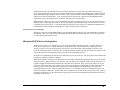
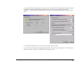
Microsoft Windows NT UPS Service Configuration
50
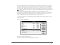
Microsoft Windows 2000/XP UPS Service Configuration
53
Operational Behavior, 2000/XP ShutDown
56
Loopback ShutDown Test
56
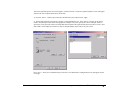
Windows NT/2000/XP Automatic Logon
57
Appendix D - Upgrade Kits
Available Upgrade Kits
58
Is Your Power On/Off Control Unit Upgrade-Compatible?
59
Upgrade Instructions
60
FCC Compliance
62
Specifications
63
Support and Warranty
64
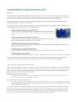
Server Technology, the world leader in Remote Power Control technology, provides a wide array of remote power
management solutions - for individual PCs and enterprise operations. For information on our complete product line take
a look at us on the World Wide Web. Our homepage address is:
www.servertech.com
Copyright (c) 1990-2003 by Server Technology, Inc.
Edition 4
301-0900-1 Rev C.
Remote Power On/Off, including the firmware and this manual, is copyrighted and contains proprietary information.
Licensed Material. Program Property of Server Technology. All Rights Reserved. No part of this publication may be
reproduced without the prior written permission of Server Technology, Inc. Only the original unaltered PDF version of
this guide may be distributed, and must be done so only in its entirety.
Remote Power On/Off, Power On/Off +Aux, AutoShutDown, ShutDown/REBOOT, and Intelligent Power Module, are
trademarks of Server Technology, Inc.
Remote Power On/Off
Table of Contents • 4
Introduction
Congratulations on your purchase of Remote Power On/Off. Built with pride in the United States of America it allows an unmanned PC
and/or peripheral devices to be safely powered on/off or rebooted from distant locations, thus eliminating the expense of running a host PC
24 hours-a-day, or minimizing down-time due to remote system or equipment lockups.
Remote Power On/Off consists of the Power On/Off +Aux control unit, cables, and the Intelligent Power Module (IPM). The control unit
transparently and passively monitors a standard analog telephone line and responds to Ring, Off-Hook, and On-Hook conditions by
sending power-ON, power-OFF, or REBOOT signals to the IPM. Remote Power On/Off can be used with or without an internal or external
modem, is ideal for use with host remote control and communications applications like pcANYWHERE, HyperAccess, and others, and is a
powerful tool for automatic rebooting of target dial-up systems that fail to answer calls. It completes the setup by introducing Remote
Power Control and can be used successfully with any computer or device capable of booting and operating upon power switching on.
In addition to Remote Power Control, the ShutDown/REBOOT versions of Remote Power On/Off include the ability to attempt an orderly
shut down of either Microsoft Windows 95/98/ME or Windows NT/XP/2000. The Windows 95/98/ME version includes Server
Technology's own AutoShutDown program which monitors either a serial port or a parallel port for notification from the Power On/Off
+Aux unit to initiate a shut down prior to a power-OFF or a REBOOT. The Windows NT/XP/2000 version utilizes Microsoft's own UPS
Service - which monitors a serial port for notification from the Power On/Off +Aux to shut down. The ShutDown/REBOOT versions will
automatically signal your computer to gracefully shut down so that "You can now safely turn off your computer" remotely.
Either version of Remote Power On/Off allows you to choose between three distinct operating modes. The Power-ON Mode allows a
device to be powered-ON by an incoming call, remain ON for the duration of the call, then automatically power-OFF after the call is
complete. This mode is ideal for traveling laptop users, support personnel, telecommuters, or anyone wishing to remotely operate or access
a distant PC or network - from anywhere, anytime - without having to leave the PC running, and without worry if it locks-up. The
REBOOT Mode is ideal for resetting (cold rebooting) any device that is normally powered on. Error or lock-up conditions can be cleared
with a phone call. Safeguards for high traffic systems make the REBOOT mode ideal for use with fax servers, dial-up access servers, and
more. The Infinite-On/Off Mode is for users that prefer direct switch-on/stay-on or switch-off/stay-off power control.
The +Aux feature of the Power On/Off control unit allows a single telephone line to be shared between a modem, the Power On/Off +Aux,
and one other telephone-line device (such as a facsimile or answering machine). This feature eliminates the need for a dedicated modem
line while also providing a unique level of security. With the +Aux Feature enabled, routine incoming calls are routed to the Auxiliary
device while modem access and power control are safely disguised. Only a specific 'secret' two-call method will enable power control
features and grant access to the modem.
It is Server Technology's intent that this product support your remote computing needs. Every attempt has been made, through design and
craftsmanship, to ensure quality and compatibility. We believe it will become an integral and truly valuable part of you're remote
computing setup and guarantee correct operation in accordance with this manual with a 1-year repair or replacement warranty.
Remote Power On/Off
Introduction • 5
About this Guide
This guide is intended to be printed. Printing this guide will provide proper clarity of the diagrams.
Remote Power On/Off has been designed to control power supplied to a PC. In general, the PC is running a communications application
that utilizes an analog modem to communicate over ordinary telephone lines. Although the manual is written with this in mind, the Remote
Power On/Off is capable of controlling power to any device that can be turned on and off by its AC source. As long as the device powers
on simply by providing power to it, the Remote Power On/Off can turn on, turn off, or reboot the device with a phone call; a modem is not
required. Refer to the following on-line document for guidelines and useful information if you are unsure about whether or not your
particular computer is capable of being turned on and off by the AC power source:
http://www.servertech.com/library/Technote/atxpowerrestart.PDF
The primary installation section of this manual describes the installation of the standard Power On/Off +Aux, model #PP02. These
instructions generically apply to all versions. Additional instructions for the Windows 95/98/ME ShutDown/REBOOT version, model
#PP03, and the Windows NT/XP/2000 ShutDown/REBOOT version, model PPNT, are contained in the Windows 95/98/ME ShutDown
Appendix B and Windows NT/XP/2000 ShutDown Appendix C respectively.
This fourth edition manual was created for electronic distribution only; it has never been published in printed form. Information contained
in this manual is not necessarily accurate for all existing Power On/Off +Aux revisions. Server Technology's original Remote Power
On/Off was introduced in 1990 and the "+Aux" version was introduced in early 1993. Server Technology only warrants that your Power
On/Off +Aux product will operate according to the manual that was originally delivered with the product. In general, if the product was
purchased in 1997 or later, then this manual will accurately reflect your fully-operational unit's behavior.
Installation should be performed only after printing and reading this manual in its entirety and with the unit configured to factory defaults
as originally received. Once the installation is complete you must determine which operating mode (either the Power-ON, REBOOT, or
Infinite-On/Off) you would like to use, then proceed to that section of this manual for specific instructions. For additional information
about the +Aux feature for line-sharing or as a security measure, refer to the +Aux Feature section; this section explains Power On/Off
+Aux's unique line-sharing feature, which is useful for allowing a single phone-line to be used for a modem, the Power On/Off +Aux, and
one other automatic answering telephone device.
Please note that Power On/Off +Aux is designed and built to monitor a single telephone line. In America, a single line is generally wired
as the two center conductors/pins within a common RJ11 phone jack. Although Power On/Off +Aux is a single-line device, it does support
complete un-monitored passing of a second line through its RJ11 telephone connectors. In addition, the primary line that is monitored is
surge-protected by a single metallic-oxide varistor (the main component in surge-protection) and two fuse-resistors (one for the modem and
a second for the auxiliary device). Although relatively rare, damage to the Power On/Off +Aux unit due to surge is not covered under the
product's warranty, and liability for damage to other equipment due to surge on the telephone line is herein expressly denied.
Remote Power On/Off
About this Guide • 6
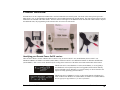
Product Overview
Pictured below are the components included with a 110VAC Remote Power On/Off system. The items in the center picture represent a
PP02 model. Note: A documentation CD-ROM may have been included instead of the printed manual. The items shown on the left are the
additional items included with a PP03 model. The items shown on the right are the additional items included with a PPNT model. Beyond
the additional items, the programming in the main unit also varies between each model.
Identifying your Remote Power On/Off version:
There are three distinct versions of Remote Power On/Off. They are Power On/Off +Aux (model #PP02), Power On/Off +Aux
ShutDown/reBOOT for Windows 95/98/ME (model #PP03), and Power On/Off +Aux ShutDown/reBOOT for Windows NT/XP/2000
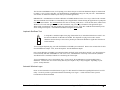
(model #PPNT). Each version can be identified by the writing on the front bezel of the main control unit and the label on the bottom:
Identifies the unit is a non-ShutDown version (model #PP02), or was originally a
non-ShutDown version [which may have been upgraded; check label on bottom].
Useful with DOS systems, Windows 3.x systems, and any AC device that does not
require an orderly operating system shut down.
Identifies the unit is a ShutDown version. A label on the bottom will indicate it is
either for Microsoft's Windows 95 (model #PP03) or Windows NT (model #PPNT).
See the appropriate AppendixB or C for more information.
Remote Power On/Off
Product Overview • 7
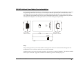
Intelligent Power Module (IPM) - 110vAC model
The Intelligent Power Module houses an electronic relay that will switch power to your computer, or any AC powered
device, on and off. The module is activated (powered ON) via a signal from the Power On/Off +Aux control unit.
Compare your module now to the illustration below and familiarize yourself with the terms that follow.
If you have purchased the 220vAC version, refer to Appendix A - page 39 - for the overview and installation.
STATUS
INPUT
0
INTELLIGENT
POWER MODULE
TM
INPUT port - a telephone-type signal cable from the Power On/Off +Aux control unit connects to this 5V DC LOGIC
SIGNAL "INPUT" port on the side of the IPM.
Status LED - this green lamp is illuminated when the IPM is in an ON state (providing power).
0 | 1 Switch - this rocker-type switch can be used as an override to manually turn the IPM ON. In the (1) position the
power is always ON. In the (0) position, power is controlled by the INPUT signal; if the INPUT port is empty, the power
is OFF. This switch must normally be set to the INPUT (0) position.
Technical information for the IPM can be found in the Specifications section.
Remote Power On/Off
Product Overview • 8
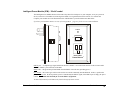
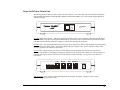
Power On/Off +Aux Control Unit
The desktop portion of Remote Power On/Off is the Power On/Off +Aux control unit. This unit monitors the telephone
line for RING, OFF-HOOK, and ON-HOOK conditions and signals the IPM to power the computer and peripherals on
and off accordingly.
TM
ON/OFF
STATUS
ON/OFF Master Power Switch - this square momentary-contact switch is used to manually control the ON/OFF signal
sent to the IPM, except when operating in the Reboot Mode. In the Power-ON or Infinite-On/Off operating modes, this
push button must be used to switch the computer on and off when operating the PC locally.
ON/OFF LED - this green lamp indicates the status of the power signal to the IPM. A fully illuminated or flashing lamp
indicates a the power signal is ON. An off lamp indicates the power signal is OFF. See the 'On/Off and Status LED'
section of Appendix A for additional information.
STATUS LED - this green lamp will always be either flashing or fully illuminated when the Power On/Off unit is
operating. The flash rate of this lamp will change according to the current phone-line condition. It will also inform you
if the PC has been powered-ON remotely since it was last powered-OFF manually. See Appendix A for additional
information.
LINE
DIP SWITCHES
MODEM
AUX
IPM PORT
POWER
DIP-SWITCHES - these switches set the Operating Mode and configure all options. Changes become effective
immediately following any active calls.
Remote Power On/Off
Product Overview • 9
LINE port - the incoming telephone line, from the wall-jack, connects to this RJ11 port.
MODEM port - a telephone cable connects out from this RJ11 port to the modem's line-in port. .
AUX port - a facsimile machine, answering machine, or other device sharing the same phone line connects to this RJ11
port.
IPM PORT - the signal cable to the IPM connects to this RJ11/12 port. With the Power On/Off +Aux
ShutDown/REBOOT version, the black end of the Y-type signal cable connects this IPM port to both the Intelligent
Power Module and a selected I/O port on a Windows 95/98/ME or Windows NT/XP/2000 system.
POWER jack - the 9vDC power plug from the wall-mount power supply attaches to this receptacle.
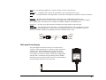
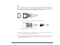
Signal Cable - the signal cable used to connect the +Aux unit to the IPM must be a RJ11 4-conductor, crossover,
telephone-type cable as shown below. Either of the two included cables will work. The ShutDown versions for
Windows 95/98/ME or Windows NT/2000/XP must use the included custom Y-cable.
Yellow
Green
Red
Black
Yellow
Green
Red
Black
Wall-mount Power Supply
The power adapter for the Power On/Off +Aux control unit is a
110VAC to 9VDC transformer, or a 220VAC to 9VDC transformer.
It supports up-to 300mA and the barrel-type plug end is wired
center-negative. The Power supply must plug into a consistently
live wall outlet or an outlet on a UPS. It must NOT be plugged into
and outlet that is switched on/off by the Intelligent Power Module.
The barrel-type power plug at the end of the six foot cord will attach
to the POWER jack on the rear of the control unit.
Remote Power On/Off
Power Supply
Output:
9VDC 300mA
+
Product Overview • 10
A sample session, Power-ON Mode:
1
The user makes a modem call to the phone number of the line attached to the Power On/Off +Aux control unit.
2
The Power On/Off +Aux unit detects the incoming RINGs and counts them. After the first ring, the Power On/Off
+Aux signals the IPM to power-ON the host PC and peripherals.
3
The line continues to ring as the PC is booting. A command in the PC's AUTOEXEC.BAT or Startup folder loads
the host/communications software (i.e. pcANYWHERE, HyperAccess, etc.), or the host program loads per its own
"launch at startup" option (through modification of the registry). The modem is initialized into answer mode.
4
The modem answers the incoming call and a connection is made. The Power On/Off +Aux sees the OFF-HOOK
condition present on the line, indicating that the line is in-use, and keeps the power ON for the duration of the call.
5
When the user is finished and ends the session, the modems disconnect (hang-up) and the ON-HOOK condition is
detected. The IPM is signaled to power-OFF.
This scenario describes a remote session using the Remote Power On/Off according to its factory default settings. There
are many interesting options to supplement using the system in other ways. See the Sample Session section for more
examples.
Remote Power On/Off
Product Overview • 11
Installation
This section covers the initial installation and testing of the Power On/Off +Aux control unit and the Intelligent Power Module (110vAC
version). For additional installation information regarding the Windows 95/98/ME and Windows NT/2000/XP ShutDown/REBOOT
versions refer to Appendix B and Appendix C respectively. For the 220VAC IPM, refer to page 39 of Appendix A.
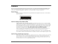
Default Settings
Installation should be performed with the factory default DIP-switch configuration as shown below. Switch numbers 2
and 5 are ON (down):
ON
1 2 3 4 5 6 7 8
Install the Intelligent Power Module (IPM)
Toggle the IPM 0|1 switch to the INPUT (0) position. Plug the IPM in-line between a live AC outlet and a multiple
outlet surge strip. Next, plug the PC and associated peripherals' power cables into the outlet strip. The power switch on
the PC and peripherals must be set and remain in the ON position. Toggle the IPM switch to the ON (1) position and the
PC and associated devices should power ON. Toggle the IPM switch back to the INPUT (0) position and the PC and
associated devices should power OFF. The switch should remain in the INPUT (0) position.
NOTE: For systems with an Uninterruptible Power Supply (UPS; a battery back-up), the UPS plugs into the live AC
outlet and the IPM plugs into an outlet provided by the UPS. The switch on the UPS must always remain on.
Insert one end of either included telephone cable into the IPM's port labeled "Input". This is now the IPM Signal Cable.
For an example of what the system should look like once installed, see the Before and After diagrams on pages 13 and 14.
Install the Power On/Off +Aux Control Unit
Position the Power On/Off +Aux Control Unit in a suitable spot near the PC. The Master "ON/OFF" switch is located on
the face of this unit, so choose a location on the desktop that is easily accessible. Next, plug the wall-mount power
supply into another live AC outlet (not controlled by the IPM) and insert the plug into the jack labeled "Power" on the
rear of the control unit. The "STATUS" light should begin to flash.
Remote Power On/Off
Installation • 12
NOTE: UPS users must attach the wall-mount power supply to a second backed-up outlet provided on the back of the
battery back-up. If not, a power outage will result in the PC powering off because the IPM will switch off if the Power
On/Off +Aux unit looses power. Do not plug the power supply into an outlet that is switched on/off by the IPM.
Insert the free end of the IPM signal cable into the port labeled "IPM PORT". The square "ON/OFF" switch should now
control the IPM. Press the switch once - the LED should illuminate, the IPM should activate, and the PC and peripheral
devices should power-ON. Press the switch again - the devices should power-OFF. This is now the Master switch for
turning the PC on and off.
Connect the telephone cable from the wall jack to the control unit's "LINE" port. Attach a second cable from the control
unit's "MODEM" port to the modem. The telephone line now passes through the Power-On/Off +Aux unit to the modem.
Before installing Remote Power On/Off:
PC
OFF ON
ON
OFF
Telephone
Wall Jack
Power
Supply
ON OFF
Power/Surge Strip
Telephone Cable
Remote Power On/Off
MR
TR
SD
RD
OH
CD
AA
HS
Modem
ON
OFF
To
Modem
Line-In
Installation • 13
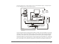
After installing Remote Power On/Off:
PC
STATUS
IPM
0
OFF ON
ON
INTELLIGENT
POWER MODULE
TM
OFF
Telephone
Wall Jack
Power
Supply
ON OFF
Power/Surge Strip
Telephone Cables
DIP SWITCHES
LINE
MODEM
AUX IPM P ORT
POWER
MR
TR
SD
RD
OH
CD
AA
HS
Modem
ON
OFF
To
Modem
Line-In
Power
Supply
Power On/Off +Aux
(back view)
IPM Signal Cable
Remote Power On/Off
Installation • 14
Operating Modes and Options
Remote Power On/Off offers three exclusive Operating Modes with several selectable options for each mode. Operating modes and
options are determined by the Power On/Off +Aux control unit's DIP-switch settings.
The two common Operating Modes are the Power-ON Mode (next page) and the REBOOT Mode (begins page 20). These operating
modes, their individual options, and the DIP-switch settings, are discussed in the following sections. Discussion of the third mode, the
Infinite-On/Off Mode, begins on page 26.
Safeguards:
The Power On/Off +Aux control unit is programmed with several safeguards which apply automatically to each operating
mode. It is important to note each as they may cause time-related functions to appear incorrect.
Wake-up Delay - Whenever power is first supplied to the Power On/Off +Aux control unit there will be a 30 second
delay before any power-ON signal is sent to the IPM. This delay can help protect the devices attached to the IPM from
power surges and transient spikes that occur during brownouts or following a blackout.
Minimum ON Time - In all cases where the power is automatically turned-ON by a function of the Power On/Off +Aux
unit, it will remain ON for a minimum of one (1) minute for a PP02, 90 seconds for a PP03, and five (5) minutes for a
PPNT. This design is to ensure a complete POST (Power On Self Test), RAM check, and complete boot whenever the
PC is powered-ON.
Minimum OFF Time - Anytime the power is turned-OFF by an automatic function of the Power On/Off +Aux unit, it
will remain OFF for a minimum of 30 seconds. This design is to ensure a complete "settle" whenever the PC is poweredOFF.
REBOOT
Inhibit Time - This timer inhibits incoming calls from initiating a reboot for 21/2 minutes whenever power is
first supplied, the IPM is instructed to turn on, or following a prior REBOOT. This guarantees the host or server system is
always allowed to fully boot and be ready to answer incoming calls before subsequent reboots are allowed; perpetual
reboots due to incoming calls that cannot be answered - because the system is still booting - are avoided. This safeguard,
designed for high-traffic systems such as fax servers, applies only to the REBOOT Operating Mode. After supplying
power to the Power On/Off +Aux unit for the first time, be sure to wait about three minutes before testing.
Remote Power On/Off
Operating Modes • 15
Power-ON Mode
The default operating mode for the Remote Power On/Off system is the Power-ON Mode. This mode allows a PC and peripherals to be
turned-ON by an incoming telephone call and automatically turned-OFF after the call is completed.
In this mode, the Power On/Off +Aux control unit monitors the telephone line for three conditions known generically as RING, OFFHOOK, and ON-HOOK. The system will react as follows:
RING:
When a call is placed to the unit, each incoming RING is counted and, after a selected ring number, the powerON signal is sent to the IPM.
OFF-HOOK:
The power-ON signal to the IPM will endure as long as RING(s) continue or OFF-HOOK exists (the call has
been answered).
ON-HOOK:
When hang-up occurs, the ON-HOOK condition is detected. After a selected delay, the power-OFF signal is
automatically sent to the IPM.
NOTE: When operating the PC locally, the Master ON/OFF switch must be used to power the system both on and off. In such cases,
when the PC is powered-ON locally by the push button, incoming calls will never alter the ON state unless the 15-Ring Turn-Off option
(described later in this section) is enabled.
Power-ON Mode Options
Power-ON Ring Number - This option sets the number of RINGs after which the Power On/Off +Aux control unit
sends the power-ON signal to the IPM. The default is one (1) RING. Optional settings are five (5), or ten (10) RINGs.
The five or ten ring options are useful as an added security feature (so that the PC will not power-ON with every call) or
to allow voice or non-modem calls to be answered prior to the power turning on.
Power-OFF Delay Time - This option sets the delay time that the control unit will wait, after ON-HOOK (hang-up) is
detected, before sending the power-OFF signal to the IPM. The default is to send the power-OFF signal one (1) second
after ON-HOOK is detected, so long as the Minimum-On-Time has expired. Optional settings are two (2) minutes, 15
minutes, and one (1) hour.
Remote Power On/Off
Power-ON Mode • 16
Note: These Power-OFF Delay Time settings are useful to support post-connection operations, such as host
software "Call-Back" services. The recommended selection for this option is two minutes. This will allow time
for a re-dial in cases where the first connect fails (usually because the host PC takes too long to fully bootup), as
well as plenty of time to re-connect if an accidental or unexpected disconnect occurs during a session.
15 Ring Turn-OFF Option - This option provides the ability to remotely turn-OFF the host PC and peripherals
anytime the power was left in a manual-ON state (the power was turned-on locally using the square Master Switch on the
front panel). With this feature enabled, an incoming call allowed to ring long enough will effect a Turn-OFF
immediately on the fifteenth RING. Subsequent calls can then be used to remotely boot the system up and keep it on for
the duration of the call.
This feature is useful if the host PC has been left powered-on without a host/communications software
running in a "wait for call mode". By placing a call to the host PC, the unanswered call will cause a power-OFF
immediately on the fifteenth ring. Another call can then be used to remotely power the system on to gain access
after the host application loads upon startup.
This feature can also be used to Turn-OFF a PC that was intentionally left in a powered-ON state. For
example, an office PC intentionally left running in the evening to perform an after-hours back-up can be turnedOFF later from home.
DIP Switch Configuration - Power-ON Mode
The following outlines the DIP switch positions for the various functions that apply to the Power-ON operating mode.
Each switch is defined as either OFF (up) or ON (down). DIP-switch changes are dynamic - selections become effective
immediately (upon the next call) without having to power-cycle the unit. Default selections are marked with an "*".
DIP switches 7 and 8 will be discussed later.
Power-ON Ring Number
DIP switches 1 and 2 are used to select the Power-ON Ring Number:
1|OFF 2|ON
Remote Power On/Off
Power-ON Ring One (1) *
1|ON
2|OFF Power-ON Ring Five (5)
1|ON
2|ON
Power-ON Ring Ten (10)
Power-ON Mode • 17
Power-OFF Delay Time
DIP switches 3 and 4 are used to select the Power-OFF Delay Time value:
3|OFF 4|OFF 1 second Power-OFF Delay Time *
3|OFF 4|ON
2 minute Power-OFF Delay Time
3|ON
4|OFF 15 minute Power-OFF Delay Time
3|ON
4|ON
1 hour Power-OFF Delay Time
DIP switch 5 determines when the Power-OFF Delay Time should apply:
5|OFF Power-OFF Delay Time only applies following hang-up, but only if the call had been answered (Offhook was detected).
5|ON
Power-OFF Delay Time always applies. *
15 Ring Turn-OFF Option
DIP switch 6 enables/disables the 15 Ring Turn-OFF option:
6|OFF 15 Ring Turn-OFF Option Disabled *
6|ON
15 Ring Turn-OFF Option Enabled
Technical Note: Because the telephone company RING signal is not always synchronized between the calling and
receiving parties, it is best to allow one extra ring when counting the rings to effect a power-ON or power-OFF. For
example, if the Power-ON Ring Number is set to five (5), allowing the line to ring six (6) times should guarantee that the
required minimum number of rings have occurred at the target end of the call.
Remote Power On/Off
Power-ON Mode • 18
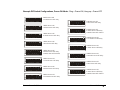
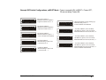
Example DIP Switch Configurations, Power-ON Mode: Ring = Power-ON, Hang-up = Power-OFF
1 RING Power-ON
1 second Power-OFF delay
ON
5 RING Power-ON
1 hour Power-OFF delay
1 2 3 4 5 6 7 8
1 RING Power-ON
2 minute Power-OFF delay
ON
ON
1 2 3 4 5 6 7 8
1 RING Power-ON
2 minute Power-OFF delay
15 RING Turn-OFF enabled
ON
1 2 3 4 5 6 7 8
10 RING Power-ON
2 minute Power-OFF delay
ON
1 2 3 4 5 6 7 8
10 RING Power-ON
15 minute Power-OFF delay
ON
1 2 3 4 5 6 7 8
10 RING Power-ON
1 hour Power-OFF delay
ON
1 2 3 4 5 6 7 8
1 2 3 4 5 6 7 8
5 RING Power-ON
15 minute Power-OFF delay
ON
5 RING Power-ON
2 minute Power-OFF delay
15 RING Turn-OFF enabled
10 RING Power-ON
1 second Power-OFF delay
1 2 3 4 5 6 7 8
5 RING Power-ON
2 minute Power-OFF delay
ON
1 2 3 4 5 6 7 8
1 2 3 4 5 6 7 8
5 RING Power-ON
1 second Power-OFF delay
ON
ON
1 2 3 4 5 6 7 8
1 RING Power-ON
1 hour Power-OFF delay
ON
1 2 3 4 5 6 7 8
1 2 3 4 5 6 7 8
1 RING Power-ON
15 minute Power-OFF delay
ON
ON
ON
1 2 3 4 5 6 7 8
10 RING Power-ON
2 minute Power-OFF delay
15 RING Turn-OFF enabled
1 2 3 4 5 6 7 8
Remote Power On/Off
Power-ON Mode • 19
REBOOT
Mode
The second operating mode is the REBOOT Mode. This mode is used to remotely reboot a device by temporarily interrupting its power
source. The REBOOT Mode provides a full coldboot, practical for resetting remote network equipment, communications or fax servers,
individual PCs, or any distributed device in a lock-up or error state. The REBOOT Mode is the reverse of the Power-ON Mode -- the
power-ON signal to the IPM is constant to keep the devices powered on. When a reboot is executed, the power-OFF signal is sent, a settle
time of 30 seconds lapses, then the power-ON signal to the IPM is restored.
NOTE: When operating in this mode the Master Switch will no longer act as a local power on/off switch! Instead, the ON/OFF switch will
serve to enable/disable the remote REBOOT function accordingly:
A flashing ON/OFF lamp indicates REBOOT is Enabled
A fully illuminated ON/OFF is lamp indicates REBOOT is Disabled.
Preface
The REBOOT Mode provides four possible methods for initiating a remote reboot -- the "No Answer REBOOT", the "OnHook REBOOT", the "Aux Port REBOOT", and the "Off-Hook (busy) REBOOT". Each method is described in the
following pages. To apply the appropriate method, it is first important to understand the four possibilities when
attempting to connect to a distant dial-up system:
•
The call placed to the host PC is answered, the
connection is made, and operation is successful.
•• The call placed to the host PC is answered, the
connection is made, but operation is unsuccessful.
••• The call placed to the host PC is never answered;
rings continue until the dialing PC gives up.
•••• Calls placed to the host PC always receive a "busy"
signal (the host modem is stuck off-hook).
Remote Power On/Off
REBOOT
Mode • 20
No Answer REBOOT
With the No Answer REBOOT method, the Power On/Off +Aux control unit will count incoming RINGs and only initiate
a reboot when a selected Ring-Count occurs and the call is not answered. If the call is answered (off-hook is detected) at
anytime, either before or after the selected Ring-Count, the reboot is canceled.
The minimum Ring-Count required to initiate a reboot can be set to either one (1) or eight (8). Set to one, any incoming
call that is not answered will initiate a reboot when the caller hangs-up (RINGs cease). Set to eight, the caller must allow
at least eight RINGs to occur before hanging-up to initiate the reboot.
This method is extremely useful for high-traffic systems, such as a bulletin-board or fax servers, where lock-up/error
conditions generally cause incoming calls to go unanswered. Using this method, the lock-up/error condition will clear
automatically when the system reboots after a failed connection attempt.
To be covered for ALL types of lock-up/error conditions, it is advisable to configure the host modem to answer on two
rings greater than the minimum Ring-Count. If the Ring-Count is set to one (1), the host should be set to answer on ring
number three (3). If the Ring-Count is set to eight (8), the host should be set to answer on ring ten (10). In cases where
the modem answers but the connection fails or operation is unsuccessful, this will allow a reboot to be forced by redialing and hanging-up after the selected Ring-Count but before the modem answers.
For example, the system will operate as follows (Ring-Count = 1):
A call placed to the host PC is answered on the third ring, the modem connection is made, and the session is
successful. A REBOOT will not occur.
A call placed to the host PC is answered on the third ring, the modem connection is made, but the session is not
successful. To force a REBOOT, place another call and allow only one (1) RING to occur, and then hang-up.
A call placed to the host PC is not answered (the line continues to ring). A REBOOT will occur automatically
when the caller gives up and hangs-up (rings cease).
On-Hook REBOOT
With the On-Hook REBOOT method, the Power On/Off +Aux control unit will initiate a reboot upon detecting the ONHOOK condition that occurs upon hang-up with every modem disconnect. Often called the "sledgehammer" method, this
is a hardware equivalent to the 'reboot on hang-up' option found in many host/communication programs. This method
will initiate a reboot after each and every inbound call.
Similar to the No Answer REBOOT method, this method also counts incoming rings to provide a reboot in cases where
incoming calls are never answered. In such cases, the caller will need to either hang-up (Ring-Count set to 1) or allow at
least eight rings to occur before giving up (Ring-Count set to 8).
Remote Power On/Off
REBOOT
Mode • 21
This On-Hook REBOOT method does not require any changes to the host PC configuration (the modem can answer on
any ring number desired). For example, the system will operate as follows (Ring-Count set to 8):
A call placed to the host PC is answered, the modem connection is made, and the session is successful. When
finished, the caller disconnects and a REBOOT occurs.
A call placed to the host PC is answered, the modem connection is made, but the session is not successful.
Hang-up to REBOOT.
A call placed to the host PC is not answered (the line continues to ring). Wait until at least eight (8) RINGs
have occurred, then hang-up to REBOOT.
+Aux Port REBOOT (Secure REBOOT)
This method, which utilizes a function of the +Aux Port Feature described later in this manual, provides the most security
for initiating a REBOOT remotely. See the +Aux Feature section for more information
IMPORTANT NOTE: When selecting this method, the telephone-line to the modem must be attached to the control
unit's AUX port (instead of the MODEM port, which will remain empty). Sharing the phone-line with another device
(i.e. an answering or facsimile machine) will not be available. Also, the host software or modem must be set to answer on
ring three (3) or higher.
Normally, the Power On/Off +Aux unit will be passive and incoming calls will be routed directly to the modem via the
AUX port. The system will never reboot automatically. A specific two-call routine must be used to initiate a reboot: The
first call, allowed to RING only one time, will serve two purposes: 1) to wake-up or 'prime' the power control functions
for a two minute period, and 2) to disable the AUX port during the two minute period to keep the modem from answering.
A second call, within the two minute window, allowed to ring the selected one or eight times (Ring-Count = 1 or 8), will
initiate the reboot upon hang-up. The system will operate as follows (Ring-Count = 8):
Calls placed to the host PC should be answered on the third ring, the connection made, and the session begin. If
the call is not answered, an error condition occurs, or a REBOOT is desired for any reason, hang-up and do the
following:
To REBOOT, dial the phone number and allow only one ring and then hang-up. This action, after 10 seconds,
will disable the AUX port and 'prime' the unit for a two-minute period. Place a second call within two minutes
and allow at least eight RINGs to occur. This will initiate the REBOOT upon hang-up (when the rings cease).
Technical Note: Because the telephone company RING signal is not always synchronized between the calling and
receiving parties, the Power On/Off unit can be 'primed' with 1 or 2 rings. To ensure only 1 or 2 rings, dial the number,
wait to hear one ring, then wait a few seconds and hang-up just before anticipating the second ring.
Remote Power On/Off
REBOOT
Mode • 22
Off-Hook (busy) REBOOT Option
The one condition that can block you from initiating an immediate reboot with Remote Power On/Off is an endless
busied-out line. If the Power On/Off +Aux unit is on the same line as the host modem, as is generally intended, and the
modem refuses to hang-up, the line will remain constantly 'busy' and remote power control will be inaccessible.
In such cases, if the host modem or fax server locks-up and fails to release the line, the only condition detectable is OFFHOOK; it will not be possible to ring the line as the caller will simply receive the busy indicator from the local telephone
carrier. For this reason, a maximum 2 hour off-hook limit can be enabled. With this Off-Hook REBOOT option enabled,
ANY off-hook condition that exceeds two hours will effect an immediate REBOOT.
Important: The off-hook limit will apply to every single continuous off-hook condition, thus limiting each call to a
maximum continuous on-line time of 2 hours.
DIP Switch Configuration - REBOOT Mode
The following outlines the DIP-switch positions for the various functions that apply to the REBOOT Operating Mode.
Each switch is defined as either OFF (up) or ON (down). DIP-switch changes are dynamic - selections become effective
immediately without having to power-cycle the unit.
NOTE: Similar to the Power-OFF Delay Time option in the Power-ON Mode, DIP-switches 3 and 4 may be used to set a
REBOOT Delay. Generally, these two switches will remain OFF (up) to provide an immediate (one second delay)
reboot. If a REBOOT Delay is desired, refer to the Power-OFF Delay Time settings on page 18 for the DIP-switch
configuration.
Selecting the REBOOT Mode
DIP-switches 1 and 2 being placed in the up position selects the REBOOT Mode:
1|OFF 2|OFF
Remote Power On/Off
REBOOT
Mode • 23
Selecting the REBOOT Method
DIP-switch 5 selects between the No Answer REBOOT and the On-Hook REBOOT methods:
5|OFF On-Hook REBOOT Method
5|ON
No Answer REBOOT Method
DIP-switches 5 and 7 select the +Aux Port (Secure) REBOOT method:
5|ON
7|ON
Ring-Count Select
DIP-switch 6 selects the minimum Ring-Count required to initiate a REBOOT when rings cease.
6|OFF Ring-Count required = Eight (8)
6|ON
Ring-Count required = One (1)
Off-Hook REBOOT Option
DIP-switch 8 enables the maximum 2-hour Off-Hook limit. Any off-hook condition exceeding 2 hours will initiate an
immediate REBOOT.
8|OFF Off-Hook REBOOT Option - Disabled
8|ON
Off-Hook REBOOT Option - Enabled
Technical Note: Because the telephone company RING signal is not always synchronized between the calling and
receiving parties, it is best to allow one extra ring when counting the rings to effect a reboot (1 or 8 rings). For example,
if the eight (8) ring option is selected, allowing the line to ring nine (9) times should guarantee that the required minimum
number of rings have occurred at the target end of the call.
Remote Power On/Off
REBOOT
Mode • 24
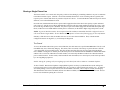
Example DIP Switch Configurations, REBOOT Mode: Power is normally ON; REBOOT = Power-OFF,
30 second delay, Power-ON.
ON
ON
ON
ON
ON
1 2 3 4 5 6 7 8
1 2 3 4 5 6 7 8
1 2 3 4 5 6 7 8
1 2 3 4 5 6 7 8
1 2 3 4 5 6 7 8
Remote Power On/Off
No Answer reBOOT
Minimum unanswered RINGs
required to initiate reboot = 8
No Answer reBOOT
Minimum unanswered RINGs
required to initiate reboot = 1
No Answer reBOOT
Minimum RINGs required = 1
2 hour Off-Hook limit Enabled
On-Hook reBOOT
Minimum Ring-Count if call
is not answered = 8
On-Hook reBOOT
Minimum Ring-Count if call
is not answered = 1
ON
ON
ON
ON
1 2 3 4 5 6 7 8
On-Hook reBOOT (reboot on hang-up)
Minimum Ring-Count = 1
2 hour Off-Hook limit Enabled
1 2 3 4 5 6 7 8
+Aux Port reBOOT (secure method)
One RING to 'prime', wait 10 seconds;
Minimum RINGs to reboot (2nd call) = 8
1 2 3 4 5 6 7 8
+Aux Port reBOOT (secure method)
One RING to 'prime', wait 10 seconds;
Minimum RINGs to reboot (2nd call) = 1
1 2 3 4 5 6 7 8
+Aux Port reBOOT (secure method)
One RING to 'prime', wait 10 seconds;
Minimum RINGs to reboot (2nd call) = 1
2 hour Off-Hook limit Enabled
REBOOT
Mode • 25
Infinite-On/Off Mode
The Power-ON Mode allows a device to be turned on, remain on for the duration of the call, but always automatically turned back off up to
1 hour after the call is ended. On the other hand, the REBOOT Mode allows a device to be powered off, but only temporarily; power
switches back on automatically after 30 seconds. Although both modes are ideal for a variety of remote communication needs, neither
allows the IPM to simply be switched on (and stay on) or switched off (and stay off). For users who need to call the host PC and power it
on or off for an infinite amount of time, the Infinite-On/Off Mode provides this ability.
NOTE: This mode utilizes functions of the +Aux Feature. As a result, line-sharing is not possible. Only the AUX port can be used Connect your modem (or other single phone device) to the AUX port and configure it to answer on RING three or greater. The
MODEM port should remain empty.
The Infinite-On/Off Mode is a variation to the Power-ON Mode. Enabled, it overrides the Power-OFF Delay Time to provide an infiniteON instead of an automatic power off. In conjunction with the 15 Ring Turn-OFF and the +Aux Feature, this option allows you to
remotely power-ON (and leave on) or power-OFF (and leave off) the Intelligent Power Module. With the modem connected to the AUX
port, routine incoming calls will be answered on the third ring (if the PC, modem, fax server, fax machine, etc. is on and waiting) and the
session will begin. Routine calls will not switch the IPM on or off. To control power, a two-call method must be used:
To turn the power ON - dial the telephone number and allow only one (1) RING, then hang-up. This action disables the
AUX port telephone line connection (and thus prevents the modem or auto-answering device from being able to answer)
and 'primes' the unit for a two minute period. A second call, after 10 seconds, will be counted toward power control
functions and power-ON upon 1, 5, or 10 RINGs. After allowing the selected number of rings, the call can be ended but
power will remain on. Once the two-minute 'window' has closed, further routine direct calls will again be allowed to pass
to the AUX port (where the modem or other answering device is attached).
To turn the power OFF - dial the telephone number and allow only one (1) RING, then hang-up. Again, this will disable
the AUX port and 'prime' the unit for two minutes. A second call, allowed to RING 15 times, will power the system OFF.
Technical Note: Because the telephone company RING signal is not always synchronized between the calling and
receiving parties, the Power On/Off unit can be 'primed' with 1 or 2 rings. To ensure only 1 or 2 rings, dial the number,
wait to hear one ring, then wait a few seconds and hang-up just before anticipating the second ring. When counting
Rings for power-ON (1,5, or 10 rings) or for power-OFF (15 rings), it is best to allow one extra ring to guarantee the
required minimum number of rings have occurred at the target end of the call.
Remote Power On/Off
Infinite-On/Off Mode • 26
DIP Switch Configuration
The following outlines the DIP switch positions for the Infinite-On/Off Mode. When the Infinite-On/Off option is
enabled, the 15 Ring Turn-OFF and +Aux Feature must also be enabled. Power can then be switched ON by 1, 5, or 10
RINGs and switched OFF with 15 RINGs. In all cases, the unit must first be 'primed' as described earlier.
Infinite-On/Off Mode Options
DIP switches 3 through 8, when set as follows, selects the Infinite-On/Off Mode:
3|OFF 4|OFF 5|ON
6|ON
7|ON
8|ON
DIP switches 1 and 2 select the Infinite-Power-ON Ring Number:
1|OFF 2|ON
Infinite-ON after Ring One (1) *
1|ON
2|OFF Infinite-ON after Ring Five (5)
1|ON
2|ON
Infinite-ON after Ring Ten (10)
In all cases, allowing 15 rings to occur will effect an Infinite-Power-OFF.
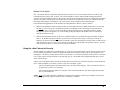
Example DIP Switch Configurations, Infinite-On/Off Mode: Switch-On/Stay-On, or
Switch-Off/Stay-Off
ON
ON
1 2 3 4 5 6 7 8
1 2 3 4 5 6 7 8
Remote Power On/Off
One RING to 'prime', wait 15 seconds;
2nd call: 1 RING to Infinite-ON
15 RINGs to Infinite-OFF
One RING to 'prime', wait 15 seconds;
2nd call: 5 RINGs to Infinite-ON
15 RINGs to Infinite-OFF
ON
1 2 3 4 5 6 7 8
One RING to 'prime', wait 15 seconds;
2nd call: 10 RINGs to Infinite-ON
15 RINGs to Infinite-OFF
Infinite-On/Off Mode • 27
+Aux Feature
The +Aux feature allows a single telephone line to be shared by a modem, the Power On/Off +Aux system, and one other telephone device,
such as a facsimile machine or answering machine - which is attached to the AUX port. This feature also provides (with or without an
auxiliary device attached) a unique level of security for the Power-ON Mode or REBOOT Mode
With the +Aux Feature enabled, routine incoming calls are routed to the auxiliary port device while modem access and power controls are
safely disguised. Only a secure 'secret' method will activate power controls and allow access to the modem.
Note: Power On/Off +Aux's line-sharing feature requires that both devices, modem and auxiliary, be capable of answering on ring number
three (3) or greater; if the modem and/or auxiliary device answer after only one (1) or two (2) rings, it will not be possible to share the line.
DIP Switch #7
DIP switch 7 controls the +Aux Feature. The specific functions of other DIP switches are not altered. To enable the
+Aux Feature place switch 7 in the ON (down) position:
ON
1 2 3 4 5 6 7 8
Installing an Auxiliary Device
The rear panel of the Power On/Off +Aux control unit contains an RJ-11 telephone jack labeled "AUX". This jack allows
a second analog telephone device to be used on the same line as the modem.
To connect a secondary (auxiliary) device, insert one end of a standard telephone cable into the port labeled AUX, and the
other end into the telephone device.
If the device is an automatic answering device, like a facsimile or answering machine, it must be configured to wait
at least three (3) rings before it will answer. Refer to the auxiliary device's operations manual for specific instructions.
Remote Power On/Off
+Aux Feature • 28
Sharing a Single Phone Line
The Power On/Off +Aux control unit, using relays, achieves line-sharing by controlling when the LINE port is continuous
to the MODEM and AUX ports. With the +Aux Feature enabled, all normal or routine incoming calls are ignored (with
respect to power control) and effectively routed to only the AUX device. To reach the MODEM and activate power control
functions, a two-call method must be used.
In an idle state, both the MODEM and AUX ports remain engaged to allow either device the capacity to place outbound
calls. However, with all routine (direct) inbound calls, both ports will only remain enabled for the first two rings. After
the second ring, the MODEM port is disabled - only the AUX port will remain engaged for the third and subsequent rings.
Hence, modem access is hidden and the auxiliary device will answer (on the third or higher ring) and operate as usual.
NOTE: In general, Both the auxiliary device(required) and the modem(recommended) should be configured to answer
calls on the third or higher RING. See the "Modem Priority Option" section on the following page for more information.
Summary: With all routine calls, the modem will never receive more than two RINGs. Thus, with the modem
configured to answer on ring three (3), it will always be disguised.
The 'Secret'
To access the modem and activate power control functions, the caller must use a specific two-call method. The first call
must RING only once, followed by hang-up. This action, after 10 seconds, will wake-up or 'prime' the Power On/Off
+Aux control unit for a two minute period. This first call does not affect the on or off power state of the Intelligent
Power Module. During the two minute period, the AUX port will be disabled while the MODEM is enabled and remains
enabled. The second call, within the two minute window, will reach only the MODEM and will be counted toward all
power control functions. In other words, calls intended to reach the modem, or to control power, must first be preceded
by a one ring/hang-up sequence.
NOTE: Placing the 'priming' call (one ring/hang-up) can be done from either a modem or a standard telephone.
Technical NOTE: Because the telephone company RING signal is not always synchronized between the calling and
receiving parties, the first call is allowed to RING up to two (2) times to wake-up the Power On/Off +Aux. To ensure a
successful 'priming' it is best to place the call, wait for one RING to be heard, wait a couple of seconds, then hang-up.
This should assure that at least one RING, but not more than two RINGs, reaches the Power On/Off +Aux unit. Be sure
to wait 10 seconds before placing the second call.
Remote Power On/Off
+Aux Feature • 29
Modem Priority Option
The +Aux Feature has been designed to optionally allow priority to be given to the modem whenever the PC is fully
booted and ready to answer calls. It allows you to choose whether or not the modem should be disguised when the
system is already ON and fully booted. If the system is off, the two-call method must always be used because the modem
will never be ready to answer (before the auxiliary device) until the PC is fully booted. However, with the PC already
ON and up-and-running in a "Waiting for Call" mode, priority can be assigned to the modem using the
host/communication application's or the modem's own "Ring Number to Answer" option as follows:
•
With the communications software and/or modem set so the modem answers on RING number three (3), the caller
will always need to use the two-call method to gain access (regardless of the system being in a powered-ON or
powered-OFF state). All routine calls will be answered by the auxiliary device. Remember, with the modem
configured to answer on ring three (3), it will normally be disguised because the modem will never routinely be
allowed more than two rings
•
With the communication software set to answer on RING number one (1) and the PC fully booted and "waiting to
answer", the modem will capture all calls - the auxiliary device will be inaccessible. If the power to the PC or
modem is off, the two-call method will still be required to 'prime' the unit and power ON the system; routine call will
reach the auxiliary device. However, once the system is fully booted, the modem will again have priority. All calls,
while the power remains on, will be answered only by the modem.
Using the +Aux Feature for Security
With or without an Auxiliary device attached to the AUX port, the +Aux Feature can be used as a simple security measure
to avoid random, miss-dialed, or otherwise unauthorized calls from booting/rebooting the PC or other equipment. By
enabling the +Aux Feature, callers unaware of the Power On/Off +Aux will always reach the auxiliary device. If the AUX
port is empty, the line will just continue to ring until they give up. The modem will be disguised and the power on/off
status will not change.
Callers aware of the Remote Power On/Off system that wish to activate/access the host PC/modem, or utilize the Remote
Power Control capabilities, will know to use the 'secret' two-call routine. Again:
The first call placed must be allowed to RING only once, followed by hang-up. After 10 seconds, the unit will
be 'primed' for a total of two (2) minutes.
The second call, placed within the two minutes, will be routed to the MODEM port and recognized towards the
Power Control functions.
NOTE: ALL power control functions, including the 15 Ring Turn Off Option of the Power-ON Mode, will require the
one ring/hang-up 'priming' sequence whenever this +Aux Feature is enabled!
Remote Power On/Off
+Aux Feature • 30
Sample Sessions
The following sample sessions are common end-user configurations. They are provided as a guideline to better understand the possible
Remote Power On/Off system configurations. Each sample is preceded by the appropriate DIP switch settings; a brief outline follows.
ON
1 2 3 4 5 6 7 8
Power-ON Mode
Power-ON Ring 1; 2 minute Power-OFF delay.
Basic configuration for use with dedicated modem line. Power-off delay supports optional host software 'callback'
feature and/or PCs with lengthy bootup times.
1
The user places a modem call to the phone number of the line attached to the Power On/Off +Aux.
2
The Power On/Off +Aux unit detects the incoming RINGs and counts them. After the first ring, the Power On/Off
+Aux signals the IPM to power-ON the host PC and peripherals.
3
The calling PC waits (line continues to ring) as the host PC is booting. A command in the host PC's
AUTOEXEC.BAT file loads the host/communications software. The modem is initialized into answer mode.
4
The modem answers the incoming call, a connection is made, and the session begins. The Power On/Off +Aux sees
the OFF-HOOK condition and keeps the power ON for the duration of the call.
5
When the user is finished and the session is ended, the modems disconnect (hang-up) and the ON-HOOK condition
is detected. After a 2 minute delay, the IPM is signaled to power-OFF.
Remote Power On/Off
Sample Sessions • 31
ON
1 2 3 4 5 6 7 8
Power-ON Mode, +Aux feature Enabled
Power-ON Ring 5; 2 minute Power-OFF delay.
Popular configuration for secure power control and optional line-sharing between modem and one other device attached
to the AUX port.
1
The user places a call to the phone number of the line attached to the Power On/Off +Aux. After one (1) ring is
heard, the caller waits a couple of seconds then hangs-up. This first call will prime the Remote Power On/Off
system.
2
After 10 seconds, but within the next 2 minutes, the user instructs their host/communications software (i.e.
pcANYWHERE) to place a second call to the host system.
3
The Power On/Off +Aux unit detects the incoming RINGs and counts them. After the fifth ring, the Power On/Off
+Aux signals the IPM to power-ON the host PC and peripherals.
4
The calling PC waits (line continues to ring) as the host PC is booting. A command in the host PC's
AUTOEXEC.BAT file, startup folder, or Windows registry loads the host/communications software. The modem is
initialized to answer on ring three.
5
The modem answers the incoming call, a connection is made, and the session begins. The Power On/Off +Aux sees
the OFF-HOOK condition and keeps the power ON for the duration of the call.
6
When the user is finished and the session is ended, the modems disconnect (hang-up) and the ON-HOOK condition
is detected. After a 2 minute delay, the IPM is signaled to power-OFF.
Remote Power On/Off
Sample Sessions • 32
ON
1 2 3 4 5 6 7 8
Power-ON Mode
Power-ON Ring 1; 15 minute Power-OFF delay.
Configuration for using the PC (with fax/modem) as a facsimile machine. Requires dedicated phone line for fax server's
fax-modem.
1
An associate, wishing to send you a fax, enters the telephone number for your fax/modem and instructs the sending
fax machine to dispatch the fax. The machine dials the number.
2
The Power On/Off +Aux unit detects the incoming RINGs. After the first ring, the Power On/Off +Aux signals the
IPM to power-ON the PC and peripherals. A command in the PC's AUTOEXEC.BAT file, startup folder, or
Windows registry loads the facsimile software (e.g. WINfax) into receive mode.
3
The calling fax machine waits (line continues to ring) as the PC is booting. If the sending fax machine waits long
enough, the receiving PC will answer and accept the fax - all in one call. If the sending fax machine times out (most
fax machines will only wait one minute), the PC will still continue to boot and remain ON for 15 minutes. The
sending machine will automatically retry (usually after a minute or two), and the facsimile transmission will be
received.
NOTE: Most facsimile machines, and humans, will automatically retry sending a fax after a failed attempt. Even so,
when giving out the telephone fax number, it is best to mention to the sender that "it may take two attempts". This
will avoid confusion, and assure receipt of the document.
4
Once the transmission is complete, the hang-up (ON-HOOK) is detected. Fifteen minutes later the IPM is signaled
to power-OFF.
Remote Power On/Off
Sample Sessions • 33
ON
1 2 3 4 5 6 7 8
REBOOT Mode, Power is normally ON
No Answer REBOOT Method; minimum rings required to effect a reboot = 1
2-hour Off-Hook (busy) REBOOT - Enabled
Popular REBOOT configuration for BBS (bulletin board server), dial-up email or access servers, or high-traffic
automated systems. Any incoming call that is not answered will initiate a reboot. Modem lock-ups that cause a busiedout line will be cleared automatically after 2 hours.
1
Calls placed to the phone number of the line attached to the Power On/Off +Aux are answered on the first ring by the
Host system or device and logon is successful. A REBOOT will not occur unless the caller remains on-line for over
two hours.
2
A user places a call to retrieve new messages from a designated dial-up E-mail server, but the call is never answered;
an error condition has occurred and the E-mail system is no longer responding. The line continues to ring until the
user's modem times out. Once the incoming RINGs cease, the E-mail server is powered-OFF, a 30 second settle time
passes, then the server is powered-ON -- A full coldboot! The same user tries again a couple of minutes later, the
call is answered, and new mail is retrieved.
3
A user places a call to his favorite BBS, but always receives a telephone company BUSY signal -- an error condition
has occurred and the BBS modem is stuck off-hook, causing the line to remain busy. Unaware to the caller, the line
has been busied-out for 1 hour 45 minutes and will REBOOT automatically in another 15 minutes (2 hour Off-Hook
REBOOT). The same caller tries again, one half hour later, and logon is successful.
Remote Power On/Off
Sample Sessions • 34
ON
1 2 3 4 5 6 7 8
Infinite-On/Off Mode
1 Ring/Hang-up to 'prime', wait 10 seconds then place second call:
5 RINGs to Power-ON, or
15 RINGs to Power-OFF
This configuration is for users who prefer the Remote Power On/Off to behave like a real switch -- to power-ON and stay
on, or power-OFF and stay off. In this mode, line-sharing is not possible; only a single phone device (i.e. modem) can be
attached to the AUX port - the MODEM port will be empty.
1
To switch power ON -- The user places a first call to the phone number of the line attached to the Power On/Off
+Aux. After one ring is heard, the caller waits a couple of seconds then hangs-up. After 10 seconds, this first call
will prime the Remote Power On/Off system for two minutes. Within the two minute 'window', the user places a
second call and allows at least five (but less than 15) RINGs -- the IPM will switch ON, after the fifth ring, and
remain ON even after the calls hangs-up.
2
The PC boots, a command in the host PC's AUTOEXEC.BAT file loads the host/communications software (i.e.
HyperAccess), and the modem is initialized to answer on ring 3. After the two minute 'window' has expired (2
minutes after the first call), the system will be in an infinite-ON state, ready to accept incoming calls. The power
will remain on during and after all sessions. Direct calls will be answered by the modem on the third ring.
3
To switch the power OFF -- The user places a call to the Power On/Off +Aux. After one ring is heard, the user
hangs-up. Again, after 10 seconds, this first call will prime the Remote Power On/Off system for two minutes.
Within the two minute 'window', the user places a second call and allows at least fifteen RINGs to occur - the IPM
will switch OFF and remain off.
Remote Power On/Off
Sample Sessions • 35
Appendix A
ON/OFF and STATUS LED Activity
The front panel of the Power On/Off +Aux control unit contains two indicator lights. These LEDs inform the user of the
current power status, present phone-line condition, and indicate whether or not the power has been activated remotely
since it was last turned off manually. The activity of both lights varies according to the Operating Mode you have
chosen.
ON/OFF Light
Power-ON and Infinite-On/Off Modes
In the Power-ON Mode and Infinite-On/Off Mode the ON/OFF light indicates the current status of the power signal sent
to the IPM. There are four possible states for this light:
•
OFF ~ The IPM should not be providing any power. The LED is solid OFF.
•
FLASHING FAST ~ The power was activated remotely via RING and is ON. In this state the LED will illuminate
2x per second.
1/4 second ON - 1/4 second OFF
•
ON ~ The power was activated manually by the master switch and is ON. The lamp is solid ON.
•
FLASHING SLOW ~ Indicates that the power was activated manually by the master switch, is ON, and the 15 Ring
Turn-Off option is enabled or the Infinite-On/Off Mode is being used In this state, the lamp will flash in a 4 second
cycle.
3 seconds ON - 1 second OFF
REBOOT
Mode
In the REBOOT Mode the ON/OFF lamp will have only three possible states:
•
FLASHING ~ The power is ON and the REBOOT function is enabled. In this state the LED will illuminate 2x per
second.
1/4 second ON - 1/4 second OFF
Remote Power On/Off
Appendix A | LED Activity • 36
•
ON ~ The power is ON and the REBOOT function is disabled. Incoming calls cannot initiate a remote reboot. LED
is ON.
•
OFF ~ A REBOOT is in progress. The power is currently OFF as part of the off>delay>on reboot cycle. Power will
turn back on within 30 seconds. The LED is solid OFF.
STATUS Light
The purpose of the STATUS LED is to validate the unit is operating, provide a visual indication of the current phone line
condition, and, in the Power-ON Mode, to announce the power has been activated remotely at least once since the last
manual power off. Following are the possible states for the STATUS LED:
ALL Operating Modes
The STATUS LED, in all operating modes, will reflect activity on the phone line. It will provide a visual indication of the
telephone company RING signal and also indicate if the line is in use (OFF-HOOK) by either the MODEM or AUX port
device. The ON-HOOK or idle state will vary with to the Operating Mode. For the examples below, a standard
telephone company six-second ring pattern (2 seconds of RING, four seconds of silence between rings) is assumed:
•
RING ~ While the line is ringing the STATUS LED will alternate between ON and flashing fast.
During the actual RING the LED will be fully illuminated. A standard ring pattern will keep the light on for two full
seconds:
ON during RING - 2 seconds
Between each ring the LED will flash fast. This is equivalent to the four second gap of silence that occurs before the
next ring. The LED will illuminate 4x per second:
Fast flash between rings - 4 seconds.
1/8 second ON - 1/8 second OFF
•
OFF-HOOK ~ While the line is in use (the modem or auxiliary device has gone off-hook), the STATUS LED will
flash slowly:
2 seconds ON - 2 seconds OFF
Remote Power On/Off
Appendix A | LED Activity • 37
Power-ON and Infinite-On/Off Modes
In the Power-ON and Infinite-On/Off operating modes, the idle (ON-HOOK) state of the STATUS LED will indicate
whether or not the power has been turned on remotely since the last time it was powered off manually. Only two distinct
flash rates will occur: either a mostly off slow flash, or a mostly on slow flash. With just a glance you will instantly know
if a phone call had activated your PC since the last time you powered it off. Following describes the two possible states:
•
OFF-on-OFF ~ The Status LED light is mostly OFF. This indicates the unit is functioning in an idle on-hook state.
The system has NOT been powered-ON remotely since it was last powered off manually. In this state, the LED light
will flash in a continuous 8 second cycle:
7 seconds OFF - 1 second ON, etc.
•
ON-off-ON ~ The Status LED light is mostly ON. This indicates the unit is functioning in an idle on hook-state.
The system HAS been remotely powered-ON at least once since it was last powered off manually. In this state the
LED will flash in the following 8 second cycle:
7 seconds ON - 1 second OFF, etc.
This feature is especially useful for users that receive facsimile transmissions by computer, but do not desire to leave the
computer on all the time. When such a user finishes their work and powers the computer off, the Status LED will revert
to the mostly OFF state. The user can feel confident the system will bootup and accept fax calls while he/she is away.
Upon return, the user need only look at the Status LED to determine whether or not the system had been powered on
during their absence. If the Status LED has switched to the mostly ON state, then the user knows the system was
remotely turned on at least once, and that he/she should bootup the computer to check for received faxes.
REBOOT
Mode
In the REBOOT Mode, the idle (ON-HOOK) state of the STATUS LED will have only three states, as follows:
•
ON ~ The LED is fully illuminated. The unit is functioning in an idle on-hook state; the line is not in use.
•
FLASHING ~ The light is flashing evenly on and off. Either a reboot is pending and the unit is counting down
towards the off>delay>on cycle or a reboot has occurred recently and the REBOOT Inhibit timer is currently
counting down. Another reboot will not be allowed until the STATUS LED goes solid ON ( 2 1/2 minutes from the
previous reboot). The light will flash as follows:
1 second ON - 1 second OFF, etc.
Remote Power On/Off
Appendix A | LED Activity • 38
220 VAC Intelligent Power Module Overview/Installation
0
INTELLIGENT
TM
POWER MODULE
STATUS
For users that have purchased the 220VAC version of Remote Power On/Off, the Intelligent Power Module is a universal
design utilizing common IEC 320 connectors. Functionally, the IPM will operate the same as described earlier in the
110V IPM section, but will require modification of a multiple outlet/surge strip specific to your country and its outlet
type. Following is an illustration of the 220 volt version and installation instructions. By following these steps, the 220
VAC IPM can be adapted for use with any 200-250 VAC, 47-63 Hz country specific power strip.
IEC 320 Male
INPUT Connector
IEC 320 Female
OUTPUT Connector
5V DC LOGIC
SIGNAL INPUT
Step 1
Using a country specific PC power cable, attach the country specific end to a live outlet, then attach the opposite end
(standard IEC 320 /C13 connector) to the IEC 320 /C14 inlet on the IPM.
Toggle the rocker-type 0|1 switch to the ON (1) position - the green STATUS lamp will illuminate. This indicates the IPM
now has power and is ON. Toggle the switch back to the INPUT (0) position - the lamp will go out.
Remote Power On/Off
Appendix A | 220VAC IPM • 39
Step 2
Locate the included cable-mount IEC 320 /C14 male inlet connector assembly (illustrated below) and a multiple outlet
power or surge-protection strip specific to your country of installation (not included). The next action requires the user to
install the IEC 320 /C14connector assembly to the end of the country specific multiple outlet strip (replacing the country
specific male plug). Follow these steps (note that all measurements are listed in millimeters):
Line (Brown Or Black)
Ground (Green/Yellow Or Green)
25.0
6.0
Neutral (Blue Or White)
Clamp
A
Cut off the country specific male end of the multiple outlet/surge strip. Strip the ends of the three electrical cords, as
shown in the above diagram, to expose 6.0 mm of each conductor.
B
Remove the screw from the IEC 320 male connector assembly and open the unit. Remove the two smaller screws
securing the Clamp. Also, remove the rubber jacket (plug bend relief) and slide it over the stripped ends onto the
cord of the multiple outlet/surge strip.
Remote Power On/Off
Appendix A | 220VAC IPM • 40
C
Loosen each screw on the three terminals, then attach the appropriate conductor to each, and tighten the screws. Be
sure to attach each conductor to the appropriate terminal, as shown in the above diagram. Also note that the inside of
the IEC320 male assembly identifies each terminal with an "N" for Neutral, "L" for Line, and a "
" symbol for
Ground (in the middle). Connect each conductor accordingly:
Neutral = Blue or White shielded conductor
Line = Brown or Black shielded conductor
Ground = Green or Green/Yellow conductor
D
Reattach the Clamp and reassemble the unit. The multiple outlet/surge strip is now adapted to connect to the
'reverse' IEC 320 /C13 universal outlet of the 220VAC Intelligent Power Module.
Step 3
Test the assembly before connecting it to the IPM by removing the IEC 320 female cable from the input end of the IPM,
and connecting it directly to the male connector of the modified multiple outlet/surge strip (bypassing the IPM). Any
device plugged into the multiple outlet/surge strip should turn ON. If the multiple outlet strip has an on/off switch, be
sure it is switched and remains ON.
Once it has been verified that the modification to the multiple outlet/surge strip has been performed correctly, install the
220 VAC IPM in-line between the two IEC 320 connectors. To test the IPM, toggle the 0|1 switch to the ON (1) position
- the devices will power-ON. Toggle the switch back to the INPUT (0) position - the devices will power-OFF. The
switch must remain set to the INPUT (0) position.
The installation of the 220 VAC Intelligent Power Module is now complete. All devices connected to the modified
power strip will now be switched on and off together by the IPM. Please note that the 220VAC IPM should not be used
to switch loads greater than 6A.
Proceed back to page 12 to continue the Remote Power On/Off installation.
Remote Power On/Off
Appendix A | 220VAC IPM • 41
Appendix B - Windows 95/98/ME ShutDown
Introduction
Windows 95, Windows 98, and Windows Millennium Edition must be shut down prior to turning off power. When a
user is at the computer, the user can perform the necessary shutdown by selecting Shut Down from the Start menu on the
task bar. With Remote Power On/Off, the user is not at the computer, and consequently may not be able to perform the
necessary shutdown prior to the power being turned off.
To solve this problem, Server Technology introduced the Power On/Off +Aux ShutDown/REBOOT for Windows 95,
model #PP03. This version contains modified firmware, an IPM/ShutDown signal Y-cable, a serial and parallel port
adapter, and custom software. These allow Remote Power On/Off to signal Windows 95/98/ME to shut down prior to
turning power off. The Y-cable connects the Remote Power On/Off to the IPM and also to either a serial or parallel port
on the Windows 95/98/ME system. The software for Windows 95/98/ME (AutoShutDown.Exe) then monitors the serial
or parallel port for the signal from the Remote Power On/Off to shut down the operating system. The Power On/Off
+Aux ShutDown/REBOOT unit will signal a shutdown to occur one (1) minute before power is turned off or a REBOOT
cycle is started.
This appendix describes the cabling, the functional changes to the Remote Power On/Off, and the AutoShutDown
software for Windows 95/98/ME. This Appendix supplements the previous sections in this guide with additional
information related to the Windows 95/98/ME shut down features of the model #PP03 Remote Power On/Off.
IPM/ShutDown Signal Y-cable
A custom Y-cable accompanies the Windows 95/98/ME ShutDown version of the Power On/Off +Aux. This cable
replaces the "IPM Signal Cable" described on page 10 and shown on page 14.
This Y-cable serves two purposes - 1) to signal the IPM to turn power on or off, and 2) to signal the AutoShutDown
software for Windows 95/98/ME to attempt a shut down of the operating system. The cable has a Y-configuration,
meaning that one end of the cable splits off to two other ends, like the lines of the letter "Y". This Y-cable connects to
the back of the Power On/Off +Aux unit into the IPM Port, and then splits off with one end going to the Intelligent Power
Module and the other end going to a ShutDown adapter attached to either a serial or parallel port on the system running
Windows 95/98/ME.
Because it is very important that the correct ends of the Y-cable go to the IPM and to the ShutDown adapter, the Y-cable
is color keyed on the two individual ends. The blue end connects into the side of the IPM, while the red end connects
into either the serial port or parallel port ShutDown adapter.
Remote Power On/Off
Appendix B | Windows 95/98/ME ShutDown • 42
The following diagram shows a complete installation with the Y-cable and ShutDown adapters. This diagram replaces
the "After installing Remote Power On/Off" diagram on page 14.
Red
STATUS
PC
IPM
To Serial Port
To Parallel Port
0
Blue
OFF ON
ON
INTELLIGENT
POWER M ODULE
OFF
Telephone
Wall Jack
Power
Supply
ON OFF
ON
OFF
Power/Surge Strip
To
Modem
Line-In
Telephone Cables
L INE
MODEM
AUX IPM P ORT
DIP SWITCHES
IPM Signal
Modem
MR
TR
SD
RD
OH
CD
AA
HS
POWER
Power
Supply
Power On/Off +Aux
ShutDown/reBOOT
(back view)
Y-Cable
ShutDown Signal
As shown in the diagram, both a serial and a parallel port adapter are included. The serial port adapter has a 9-pin female
connector to attach to a serial port on the Windows 95 system. Note: A serial port on a PC can be either a 9-pin male or
a 25-pin male. If your system provides a 9-pin port the adapter will connect directly. If the serial port is a 25-pin type,
you will need to obtain a generic 25-pin female to 9-pin male converter in order to attach the serial ShutDown adapter.
The parallel port adapter has a 25-pin male connector to attach to a parallel port on the 95/98/ME system. A parallel port
is always 25-pin female on the PC. Both adapters have a red dot to indicate that the red end of the Y-Cable connects into
them. Select the adapter, serial or parallel, that is appropriate for an available port on the Windows 95/98/ME system.
Remote Power On/Off
Appendix B | Windows 95/98/ME ShutDown • 43
Functional Changes to the Remote Power On/Off
Due to the modified firmware in the Power On/Off +Aux ShutDown/REBOOT control unit, there are some minor
functional variations from those described earlier in this guide. All changes are related to the addition of the shutdown
function.
Minimum ON Time:
The Minimum ON Time, described earlier on page 15, has been increased from one (1) minute to 90 seconds. This
increase is to give additional time for the system to load Windows 95/98/ME and the AutoShutDown software prior to a
shutdown signal occurring.
ShutDown Delay Time:
In addition to the selected Power-OFF Delay Time, described earlier on pages 17 and 18, the amount of time until a
power-off or a reboot occurs has been increased by one (1) minute. This additional one minute is known as the
ShutDown Delay Time and is the additional time allotted for the ShutDown to occur. After the selected Power-OFF
Delay Time has expired, the ShutDown signal is asserted, the ShutDown Delay counts down, and the power switches
OFF one (1) minute later.
On/Off Master Power Switch and On/Off LED:
When operating Remote Power On/Off in the Power-ON or Infinite-On/Off modes, the square Master ON/OFF push
button and the corresponding LED operate differently than described earlier. The operation of the pushbutton is not
altered if the REBOOT Mode has been selected. For the Power-ON and Infinite-On/Off modes with a PP03 unit, the push
button will cycle through three states, each indicated by the LED as follows:
Power=Off
LED=Off
ress
np
butto
or 1 mn pr
inu ess
te
tto
bu
Power=On
LED=Blinking
Shutdown Started
Power=On
LED=On
but ton press
Remote Power On/Off
Appendix B | Windows 95/98/ME ShutDown • 44
Starting with the power OFF and the LED off, pressing the button once will turn power ON and the LED will go on
green. Pressing the button a second time will signal a shutdown to the Windows 95/98/ME system and the LED will start
to blink, indicating a shutdown has been started. After one (1) minute, the shutdown will be complete, and power will
turn OFF automatically. If you wish to turn power off before the one minute shutdown delay automatically expires,
pressing the button a third time will turn power off immediately.
With the button working this way, a user at the Windows 95 system would turn power ON by pressing the button once.
When the user is ready to turn the system off, the user only needs to press the button again. The user does not even have
to perform a shut down from the Start menu -- pressing the button will cause the Power On/Off +Aux
SHUTDOWN/REBOOT unit to automatically shut down Windows, turning the power OFF one minute later.
MODEM and AUX port disengage:
During the one minute ShutDown Delay period, both the MODEM and AUX ports will automatically be disabled
(disengaged). This will avoid incoming calls causing potential problems that might otherwise occur if the modem were
to answer during the shutdown process.
AutoShutDown Software for Windows 95/98/ME
AutoShutDown.Exe for Windows 95/98/ME monitors the serial or parallel port to which the ShutDown adapter is
attached. When the Remote Power On/Off signals a shutdown to occur, the software will detect the signal and attempt to
force the operating system to shut down.
To install the software, place the AutoShutDown diskette in the floppy drive and, from the Start menu, choose Run. In
the Open box, type "A:\SETUP" or "B:\SETUP", whichever is appropriate. If you are not in possession of the included
diskette, the software can be obtained via anonymous FTP at the following address:
ftp://ftp.servertech.com/pub/autoshutdown
Copy the ASD-105.ZIP file, unzip it, then execute the ASD-105.EXE file to install.
The installation is very simple and only installs a few files and adds a few keys and values to the Windows registry. The
only installation option is for the target directory, though we suggest you use the default.
After the installation is complete, you should attach the ShutDown adapter and cable, if you have not already done so,
and restart Windows. When Windows restarts, AutoShutDown will automatically execute, even before any other
applications that start automatically, and even before the Windows Logon box.
Remote Power On/Off
Appendix B | Windows 95/98/ME ShutDown • 45
The first time AutoShutDown runs, it will prompt you to choose the port to which the ShutDown adapter is attached and
to enable it. Once you have done this, you should minimize AutoShutDown and go on with your work. AutoShutDown
will continue to monitor the shutdown port while you run other applications.
IMPORTANT: AutoShutDown can initiate a Windows 95/98/ME shutdown in one of two ways, either forced or normal.
The forced method causes Windows to immediately close all applications without allowing the applications to prompt the
user to save unsaved data. The normal method is the same as selecting "Shut Down..." from the Start menu, which causes
Windows to first ask each application if it is OK to shutdown, only proceeding to shutdown if all applications agree.
When asked, an application with unsaved data may prompt the user to save. Since this would halt the shutdown process
while waiting for a response, AutoShutDown defaults to using the forced method.
Loopback ShutDown Test
A simple RJ-11 modular loopback test plug, illustrated at left, is included with the Power On/Off +Aux
SHUTDOWN/REBOOT for Windows 95/98/ME. This loopback test plug can be used to test the
shutdown function directly at the serial or parallel port without the ShutDown signal cable from Power
On/Off attached.
To test using the loopback plug, start with the Windows 95/98/ME system turned off. Remove the red end of the Y-cable
from the ShutDown adapter. Next, insert the loopback into the ShutDown adapter.
Power-on the Windows 95/98/ME system using the Master ON/OFF switch on the Power On/Off +Aux, allowing the PC
to boot normally and load AutoShutDown. If no errors occur, AutoShutDown will end up in the Task Bar (unless the
Auto Hide feature is enabled) to indicate it is monitoring the selected port.
To test AutoShutDown, remove the loopback plug. Upon removal, the AutoShutDown program should initiate a
ShutDown. Note that the "You can now safely turn off your computer" may or may not appear - depending on your
system - shortly thereafter.
Automatic Windows Logon
Please see the information toward the bottom of page 57 in this manual for information regarding Microsoft's Tweak UI
utility. Tweak UI provides a gui-based method for automating a user logon — useful when the remote system is
booted/rebooted while unattended.
Remote Power On/Off
Appendix B | Windows 95/98/ME ShutDown • 46
Appendix C - Windows NT/2000/XP ShutDown
Introduction
Windows NT, Windows 2000 and Windows XP must be shut down prior to turning off power. When a user is at the
computer, the user can perform the necessary shutdown manually. With Remote Power On/Off, the user is not at the
computer, and consequently may not be able to perform the necessary shutdown prior to the power being turned off.
To solve this problem, Server Technology introduced the Power On/Off +Aux SHUTDOWN/REBOOT for Windows NT,
model #PPNT. This version contains modified firmware, an IPM/ShutDown signal Y-cable, and a serial port adapter.
Working with the UPS Service that exists in Windows NT/XP/2000, these items allow Remote Power On/Off to signal
Windows to shut down prior to turning power off. The Y-cable connects the Remote Power On/Off to the IPM and also
to a serial port on the Windows NT/2000/XP system. The UPS Service for Windows then monitors the serial port for the
signal from the Remote Power On/Off to shutdown the operating system. The Power On/Off +Aux ShutDown/REBOOT
unit will signal a shutdown to occur 3 minutes and 30 seconds before power is turned off or a REBOOT cycle is started.
This appendix describes the cabling, the functional changes to the Remote Power On/Off, the configuration of the UPS
Service built into Windows NT 3.51+, and also the configuration of the newer UPS Service specific to Windows 2000
and XP. Also, this appendix identifies how to obtain information from Microsoft for enabling the AutoAdminLogon
feature of Windows NT in order to bypass the <Ctrl><Alt><Del> key sequence that is normally required to log on.
IPM/ShutDown Signal Y-cable
A custom Y-cable accompanies the Windows NT/2000/XP ShutDown version of the Power On/Off +Aux. This cable
replaces the "IPM Signal Cable" described on page 10 and shown on page 14.
This Y-cable serves two purposes - 1), to signal the IPM to turn power on or off, and 2) to signal the UPS Service of
Windows NT/2000/XP to shut down the operating system. The cable has a Y-configuration, meaning one end of the
cable splits off to two other ends, like the lines of the letter "Y". This Y-cable connects to the back of the Power On/Off
+Aux unit into the IPM Port, and then splits off with one end going to the Intelligent Power Module and the other end
going to the ShutDown adapter attached to a serial port on the Windows system.
Because it is very important that the correct ends of the Y-cable go to the IPM and to the ShutDown adapter, the Y-cable
is color keyed on the two individual ends. The blue end connects into the side of the IPM, while the red end connects
into the serial port ShutDown adapter.
Remote Power On/Off
Appendix C | Windows NT/2000/XP ShutDown • 47
The following diagram shows a complete installation with the Y-cable and ShutDown adapter. This diagram replaces the
"After installing Remote Power On/Off" diagram on page 14.
STATUS
NT
IPM
NT/NW
Red
PC
To Serial Port
0
Blue
OFF ON
ON
INTELLIGENT
POWER M ODULE
OFF
Telephone
Wall Jack
Power
Supply
ON OFF
ON
OFF
Power/Surge Strip
To
Modem
Line-In
Telephone Cables
L INE
MODEM
AUX IPM P ORT
DIP SWITCHES
IPM Signal
Modem
MR
TR
SD
RD
OH
CD
AA
HS
POWER
Power
Supply
Power On/Off +Aux
ShutDown/reBOOT
(back view)
Y-Cable
ShutDown Signal
As shown in the diagram, a serial port adapter labeled "NT/NW" is included. This serial port adapter has a 9-pin female
connector to attach to a serial port on the Windows NT/2000/XP system. The PPNT system with this adapter is also
capable of notifying certain Novell Netware systems to shut down (hence the "NW" on the adapter). For information
about shutting down a Novell Netware system, please contact Server Technology's Technical Support Department.
Note: A serial port on a PC can be either a 9-pin male or a 25-pin male connector. If your systems provides a 9-pin port
the adapter will connect directly. If the serial port is a 25-pin type, you will need to obtain a generic 25-pin female to 9pin male converter in order to attach the ShutDown adapter.
Remote Power On/Off
Appendix C | Windows NT/2000/XP ShutDown • 48
Functional Changes to the Remote Power On/Off
Due to the modified firmware in the Power On/Off +Aux ShutDown/REBOOT unit, there are some minor functional
variations from those described earlier in this guide. All changes are related to the addition of the shutdown function.
Minimum ON Time:
The Minimum ON Time, described on page 15, has been increased from 1 to 5 minutes. This increase gives additional
time for the system to load Windows NT/2000/XP and start the UPS Service prior to a shutdown signal occurring.
ShutDown Delay Time:
In addition to the selected Power-OFF Delay Time described earlier, the amount of time until a power-off or a reboot
occurs has been increased by three and one-half (3.5) minutes. This additional time is known as the ShutDown Delay
Time and is the additional time allotted for the ShutDown to occur. After the selected Power-OFF Delay Time has
expired, the ShutDown signal is asserted, the ShutDown Delay counts down for the 3.5 minutes, then the power switches
OFF. As defined further in this appendix, Microsoft's UPS Service has a minimum 'grace' period of two-minutes. This
means the UPS Service itself will not begin the actual shut down until the PPNT unit's ShutDown signal has been
actively asserted for two minutes, which leaves a total of 90 seconds for the actual operating system shut down to take
place.
On/Off Master Power Switch and On/Off LED:
ds
on
Power=Off
LED=Off
ress
np
tto
bu
butto
n
3 minutes 3 press
0s o
ec r
When operating Remote Power On/Off in the Power-ON or Infinite-On/Off mode, the square Master ON/OFF push
button and the corresponding LED operate differently than described earlier. The operation of the pushbutton is not
altered if the REBOOT Mode has been selected. For the Power-ON and Infinite-On/Off modes with a PPNT unit, the
push button will cycle through three states, each indicated by the LED as follows:
Power=On
LED=Blinking
Shutdown Started
Remote Power On/Off
Power=On
LED=On
but ton press
Appendix C | Window s NT/2000/XP ShutDown • 49
Starting with the power OFF and the LED off, pressing the button once will turn power ON and the LED will go on
green. Pressing the button a second time will signal a ShutDown to the Windows NT/2000/XP system and the LED will
start to blink, indicating a ShutDown has been started. After 3 minutes and 30 seconds, the ShutDown will be complete,
and power will turn off automatically. If you wish to turn power off before the 3 minute 30 second ShutDown delay
automatically expires, pressing the button a third time will turn power off immediately.
With the button working this way, a user at the Windows NT system would turn power ON by pressing the button once.
When the user is ready to turn the system off, the user only needs to press the button again. The user does not even have
to manually perform a shut down -- pressing the button will cause the Power On/Off +Aux ShutDown/REBOOT unit to
automatically shut down Windows, turning the power OFF 3 minutes and 30 seconds later.
MODEM and AUX port disengage:
During the 3 minute 30 second ShutDown Delay period, both the MODEM and AUX ports will automatically be disabled
(disengaged). This will avoid incoming calls causing potential problems that might otherwise occur if the modem were
to answer during the shutdown process.
Windows NT UPS Service Configuration
Windows NT, versions 3.51+, includes a service for an Uninterruptible Power Supply (UPS). Typically, this service
starts when NT boots, prior to a login, and monitors signals from a UPS. When a UPS detects a utility failure and
switches to battery power, the UPS signals the UPS Service to let NT know that a limited amount of run-time is left
before the batteries run down. In response, after a configured amount of battery run-time, the UPS Service initiates a safe
and orderly shut down of the operating system to prepare for the impending power loss.
All of this is accomplished by the UPS Service monitoring two pins on a serial port. One pin signals a Power Failure and
the other pin signals a Low Battery condition.
When the NT system is connected to a UPS, the Power Failure pin is signaled when the UPS detects a power failure and
switches to battery. When the battery runs down, the UPS Low Battery pin is signaled. With a UPS, the UPS Service is
typically configured with the documented run-time of the batteries in the UPS. Thus, when a power failure occurs, the
UPS service knows how long it can continue to run before having to shut down. During this run-time, notifications are
made to the users of the system that a power failure has occurred and that they should finish their work before the
impending shut down occurs. After the configured run-time, or if a Low Battery signal occurs during the run-time, the
UPS Service initiates a shut down. After the shut down is complete it will be safe for the system to lose power, either by
the batteries running out or by the UPS turning off in response to a Remote UPS ShutDown signal from the UPS Service
(supported on some UPSs).
Remote Power On/Off
Appendix C | Windows NT/2000/XP ShutDown • 50
Remote Power On/Off for Windows NT, model #PPNT, makes use of the UPS Service much the same way as a UPS
does. Whenever Remote Power On/Off is going to power the system OFF, it signals the UPS Service to ShutDown the
operating system before doing so. The Remote Power On/Off, however, does not act entirely like a UPS. Both the
Power Failure and Low Battery signals occur at the same time and the amount of time before the power is turned OFF is
fixed at 3 minutes 30 seconds. Thus, the UPS Service must be configured appropriately for these operating parameters of
Remote Power On/Off.
There are two parts to configuring the Windows NT UPS Service for use with the Remote Power On/Off -- 1)
configuring the service to automatically startup when Windows NT loads, and 2) configuring the service for the proper
COM port and operating parameters of the Remote Power On/Off. The following screen shots show the required
settings. See Microsoft's help for more information about the various items on each screen.
1) To configure the NT UPS service to automatically startup when Windows NT loads, begin by selecting "Services"
from the Control Panel.
The Services window will be displayed:
Click on "UPS" and then the "Startup" button.
The UPS Service startup parameters will be displayed (shown next page).
Remote Power On/Off
Appendix C | Windows NT/2000/XP ShutDown • 51
2) Choose the options as illustrated below, then click OK:
3) To configure the UPS Service for the proper COM port and operating parameters of the Remote Power On/Off, select
"UPS" from the Control Panel. The UPS window will be displayed:
Selected the appropriate COM port and choose the other options as shown above, then click OK.
Remote Power On/Off
Appendix C | Windows NT/2000/XP ShutDown • 52
Windows 2000/XP UPS Service Configuration
Windows 2000 and Windows XP, similar to Windows NT, includes a service for an Uninterruptible Power Supply
(UPS). The mechanism for notifying Windows 2000/XP to shut down is nearly the same as for NT. The only difference
between Windows NT and Windows 2000/XP is the software used to monitor the serial port for the ShutDown
notification from the Power On/Off +Aux. In particular, in place of Microsoft’s previous NT UPS Service, a new ‘UPS
Service’ now exists in the Power Options category of the Windows 2000/XP control panel. The following instructions
define the necessary software components and the correct configuration for the new Windows 2000/XP UPS feature to
operate with the Power On/Off +Aux ShutDown/REBOOT, model #PPNT.
Windows 2000 Service Pack 1
Service Pack 1, or later, for Microsoft Windows 2000 is required. The Service Pack update will correct problems that
exist in the original release of Windows 2000, including problems in the newer UPS feature. To verify that Service Pack
1 has been installed, select ‘My Computer’ on the desktop and click the right mouse button. Next, left-click the mouse
while selecting ‘Properties’. The screen that appears should include the following information about the system:
Microsoft Windows 2000
5.00.2195
Service Pack 1
If no Service Packs are indicated, you must contact your system administrator or Microsoft for an update. At the time
this guide was created, Service Pack 2 was the current Service Pack release and no problems have been noted. As is
always the case, it is best to keep your system(s) up-to-date with the latest Service Pack. No known problems have been
found with the UPS Service present with XP which, at the time this guide was created, was identical to the UPS Service
present with Windows 2000 Service Pack 1.
Windows 2000/XP UPS Service Configuration
Configure the Windows 2000 UPS Service according to the following instructions and sample screens:
1) Select and double-click the "Power Options" icon in the Windows 2000 Control Panel.
Remote Power On/Off
Appendix C | Windows NT/2000/XP ShutDown • 53
The Power Options Properties screen will appear. Click the UPS tab. The Power Options Properties screen will appear
similar to the screen capture down below (on the left).
2) Press the ‘Select...’ button to proceed to the UPS Selection screen (shown below, right)
3) On the UPS Selection screen specify "Generic" as the manufacturer type. Next, click on “Custom” in the ‘Select
model:’ field, then proceed to choose the appropriate COM port. Be sure to specify the correct COM port; failure to
specify the correct port may result in a bootup>shut down loop that will require booting into safe mode to correct. Note
that ‘COM1’ in the sample screen below is only an example and may not be correct for your system.
Press ‘Next >‘ when you are finished with your selection. The UPS Interface Configuration screen will appear (shown
next page).
Remote Power On/Off
Appendix C | Windows NT/2000/XP ShutDown • 54
4) On the UPS Interface Configuration screen (shown below, left), enable the UPS Signal Polarity options as illustrated.
Click ‘Finish’ to return to the Power Options Properties screen (see screen on previous page, left). Press the
‘Configure...’ button on the Power Options Properties screen to proceed to the UPS Configuration screen (shown below,
right).
5) On the UPS Configuration screen (above right), configure the options as shown.
6) Press ‘OK’ to return to the Power Options Properties screen (see screen on previous page, left). To commit the new
settings, choose ‘OK’ or ‘Apply’. The UPS Service will attempt to enable.
Remote Power On/Off
Appendix C | Windows NT/2000/XP ShutDown • 55
Operational Behavior, Windows 2000/XP ShutDown
Configured as shown in the previous screen shots, and after a call initiates a power-OFF or a REBOOT, the Remote
Power On/Off and the Windows 2000/XP UPS Service will work together in the following sequence:
Time
0
5 sec.
35 sec.
65 sec.
95 sec.
120 sec.
121 to 209 sec.
210 sec.
Event
Power failure signaled by Remote Power On/Off
First warning message that a power failure has occurred
Second warning message that a power failure has occurred.
Third warning message that a power failure has occurred.
Last warning message that a power failure has occurred.
Final shut down message. Operating system shut down begins.
Shut down progresses and completes.
Remote Power On/Off turns power off.
[if rebooting]
240 sec.
Remote Power On/Off turns power on.
Note: These are approximate times. The Windows NT/2000/XP warning messages may take longer before being
displayed. Also, an individual Remote Power On/Off may have a variance of up to +/-10% of the programmed
ShutDown delay of 3 minutes 30 seconds.
Loopback ShutDown Test
A simple RJ-11 modular loopback test plug, illustrated at left, is included with the Power On/Off +Aux
SHUTDOWN/REBOOT for Windows NT/2000/XP. This loopback test plug can be used to test the
shutdown function directly at the serial port without the ShutDown signal cable from Power
On/Off attached.
To test using the loopback plug, start with the Windows NT/2000/XP system turned off. Remove the red end of the Ycable from the ShutDown adapter. Next, power on the Windows NT/2000/XP system using the Master ON/OFF switch
on the Power On/Off +Aux and allow the PC to boot normally and run the UPS Service.
Remote Power On/Off
Appendix C | Windows NT/2000/XP ShutDown • 56
To test the UPS Service, insert the loopback plug into the RJ11 end of ShutDown adapter. Within 15 seconds of
insertion, the first warning message from the Windows NT/2000/XP UPS Service should appear. The shut down has
been initiated.
Remote Power On/Off
Appendix C | Windows NT/2000/XP ShutDown • 57
Windows NT/2000/XP Automatic Logon
When a Windows NT system boots, the operating system expects a local user to press the <Ctrl><Alt><Del> key
sequence to bring up the logon dialog box from which the user will login with their user name and password. This poses
a problem for remote booting since a user is not at the system to press the expected key sequence. Similarly, Windows
2000 and Windows XP may require a user be present to provide manual login information as well.
Fortunately, Microsoft has provided a means of automating the logon procedure so that the system can boot using a
default user name, default password, etc., all while the system is unattended. This feature of NT/2000/XP is generally
known as the Automatic Logon feature, or the AutoAdminLogon.
Correct, up-to-date Instructions for enabling the Automatic Logon feature should always be obtained from Microsoft.
Specifically, the Microsoft Support Knowledge Base should be searched and any related question should be directed to
Microsoft.
At the time this guide was created, the Knowledge Base was found to contain the following three articles containing
information about enabling the Automatic Logon.
Article ID # Q97597
Title: "How to Enable Automatic Logon in Windows NT 3.x and 4.0"
Applies to Windows NT Server and Workstation versions 3.51 and 4.0, and also Windows 2000 Server
Article ID # Q234562
Title: "How to: Enable Automatic Logon in Windows 2000"
Applies to Microsoft Windows 2000 Professional
Article ID # Q315231
Title: "How to Enable Automatic Logon in Windows"
Applies to Windows XP Home Edition, Windows XP Professional, and Windows XP 64-Bit Edition
Also available from Microsoft is a set of utilities called Tweak UI. The current version at the time of this publication
was Tweak UI version 1.33, compatible with Windows 95, 98, Millenium Edition, NT and 2000. For Windows XP a
compatible Tweak UI version could be found with Microsoft's PowerToys for Windows XP. The Tweak UI utilities are
found in the Control Panel after installation. The Logon tab within Tweak UI provides a gui-based method for
automating a user logon. To obtain Tweak UI, go to www.microsoft.com and search for "Tweak UI".
Remote Power On/Off
Appendix C | Windows NT/2000/XP ShutDown • 58
Appendix D - Upgrade Kits
Server Technology offers three distinct versions of Remote Power On/Off +Aux: 1) Model #PP02, a non-shutdown
version ideal for use with systems or devices that do not require an orderly shut down; 2) Model #PP03, a ShutDownequipped version capable of attempting an orderly shut down of Microsoft's Windows 95/95/ME; 3) Model #PPNT, a
ShutDown-equipped version capable of attempting an orderly shut down of Microsoft's Windows NT/2000/XP.
Server Technology introduced its original Power-On product in early 1990, but it was not until early 1993 that the thirdgeneration "+Aux" model was released. At that time, Microsoft's DOS and Windows 3.1 were the dominant operating
systems. Neither required an orderly shut down, and the non-shutdown "+Aux" model PP02 was the only available
version. In late 1995, after Microsoft's release of Windows 95, Server Technology introduced the model PP03. Shortly
thereafter, following Microsoft's Windows NT v3.51, Server Technology released the model PPNT.
As many users of the original PP02, and even the PP03, have subsequently progressed to newer Microsoft operating
systems over time, the need for orderly shut down has been introduced or has changed from a Win95/98/ME need to that
of WinNT/2000/XP. In response, Server Technology has created several upgrade kits that allow the Power On/Off +Aux
control unit to be converted to an alternate model. Contact Server Technology's Sales Department at 1-800-835-1515 for
further information, including pricing, or to place an order.
Available Upgrade Kits
•
Part #PP05-0-1: Upgrade kit to convert a Power On/Off +Aux model PP02 (non-ShutDown) to a model PP03
(with Windows 95/98/ME ShutDown support).
Items in kit: AutoShutdown v1.05 diskette (3 ½" floppy), custom Y-cable, 9-pin serial port ShutDown adapter,
25-pin parallel port ShutDown adapter, RJ-type Loopback Test Plug, "C795" upgrade ROM for the Power
On/Off +Aux control unit, and a stick-on label for the bottom of the unit.
•
Part #NTUP-0-1: Upgrade Kit to convert a Power On/Off +Aux model PP02 (non-ShutDown) to a model
PPNT (with Windows NT/2000/XP ShutDown support).
Items in kit: Custom Y-cable, "NT/NW' serial port ShutDown adapter, RJ-type Loopback Test Plug, "C7NT"
upgrade ROM for the Power On/Off +Aux control unit, and a stick-on label for the bottom of the unit.
•
Part #NTUP-0-2: Upgrade Kit to convert a Power On/Off +Aux model PP03 (with Windows 95/98/ME
ShutDown) to a model PPNT (with Windows NT/2000/XP ShutDown support).
Items in kit: "NT/NW" serial port ShutDown adapter, RJ-type Loopback Test Plug, "C7NT" upgrade ROM for
the Power On/Off +Aux control unit, and a stick-on label for the bottom of the unit.
Remote Power On/Off
Appendix D | Upgrade Kits • 59
Is Your Power On/Off Control Unit Upgrade-Compatible?
Only "+Aux" versions of Remote Power On/Off are capable of being upgraded. "+Aux" versions are easily identified by
the writing on the front bezel of the Power On/Off control unit. Your unit must have either "Power On/Off +Aux" or
"POWER ON/OFF +Aux SHUTDOWN/REBOOT" printed on its face.
All "+Aux" versions are ultimately compatible with any of the three upgrade kits. However, before purchasing or
performing an upgrade you will need to open the unit and look at the circuit board to verify the following:
I) The original ROM chip at position U2 is pressed into a socket (it is removable, not soldered to the board)
II) Position R14 does not contain a resistor (it should contain a solid jumper wire or nothing)
To verify your unit is fully user-upgradable, begin by removing all of the telephone cables and the power connection
from the rear of the Power On/Off +Aux control unit. NOTE: This step will cause the Intelligent Power Module (IPM) to
deactivate and power-OFF the attached devices. If necessary, the IPM's 0|1 switch can be toggled to the "1" position
(override-ON) before disconnecting the cables in order to keep the IPM in an ON state.
Next turn the unit upside down and remove the four Phillips-head screws from the unit. Once these are removed, the top
half of the control unit can easily be removed to expose the unit's circuit board. Following is a picture of the circuit
board. On it, both the ROM chip location (U2) and position R14 are outlined in white.
Remote Power On/Off
Appendix D | Upgrade Kits • 60
•
Check position U2 on your unit. This is the location of the ROM chip. Is the ROM chip in a socket
(removable), or is the ROM chip soldered directly to the circuit board (not removable)?
•
Check position R14 on your unit. Does R14 contain a resistor, similar to the following picture?
NOTE: Color of resistor and stripes may vary.
If the ROM is in a socket and R14 does not contain a resistor, then your unit is fully compatible with any available
Upgrade Kit. Proceed to order the desired kit or continue with the upgrade by proceeding to the next section titled
Upgrade Instructions.
If the ROM chip is soldered directly to the circuit board, or R14 contains a resistor, then you must call Server Technology
to arrange to have the unit sent in for a hardware upgrade. Specifically, the ROM will need to be removed and a socket
added and/or the resistor will need to be removed and replaced with a simple jumper wire. Server Technology will
charge a small fee for this service in addition to the cost of the desired Upgrade Kit. Refer to the Warranty & Support
section of this manual for instructions on obtaining a Return Merchandise Authorization to have the unit updated if your
unit's ROM is not removable and/or R14 contains a resistor. Be ready to provide the necessary information with respect
to the status of the ROM chip at position U2 and whether or not a resistor is present at position R14.
Upgrade Instructions
In addition to the #1 Phillips-head screwdriver required to open the Power On/Off +Aux control unit, you will also need
to have a chip puller or a small flat-blade screwdriver for removing the original ROM at position U2 (see picture on
previous page). Follow these instructions:
1) If you have not already done so, start by disconnecting power and all other cable connections from the Power On/Off
+Aux control unit. Remove the four screws on the bottom of the unit and remove the top half of the unit.
2) If possible, take measures to properly gound oneself, prior to proceeding, in order to avoid static discharge problems.
3) Identify ROM position U2 using the picture on the previous page. Use a chip puller or a small flat-blade screwdriver
and carefully remove the original ROM by pulling it straight up with the chip puller. If using a small flat-blade
screwdriver, pry the ROM lose by getting the blade between the ROM and the socket while avoiding direct contact with
the circuit board. Alternate between both ends of the ROM by prying in small steps until the original ROM is free from
the socket.
Remote Power On/Off
Appendix D | Upgrade Kits • 61
4) Identify the correct direction to insert the new Upgrade ROM into the socket. Look at the socket on the circuit board.
Make note that one end of the socket is notched, the end closest to the side of the unit. One end of the new ROM is also
notched. To install the ROM correctly, be sure that the notch on the socket and the notch on the ROM are aligned on the
same side. Refer to the picture two-pages back, and the following illustration to help identify the proper alignment.
(c) Copyright 1995-2002
Server Technology, Inc.,USA
RPC C795
5) Carefully insert the new Upgrade ROM chip into the socket. Be sure that all pins seat correct as you proceed to
evenly press the ROM into place.
That's it! Now just reattach the lid and your Power On/Off +Aux control unit is ready for use. Refer to this manual,
specifically Appendices B or C, for information on installing and using the additional items included with the Upgrade
Kit, and for configuration of the software element required for processing the orderly operating system shut down.
Remote Power On/Off
Appendix D | Upgrade Kits • 62
FCC Compliance Information
Notification To The Telephone Company
This equipment complies with Part 68 of the FCC Rules.
The REN is useful to determine the quantity of devices you may connect to your telephone line and still have all of those
devices ring when your telephone number is called. In most, but not all areas, the sum of the RENs of all devices
connected to one line should not exceed five (5.0). To be certain of the number of devices you may connect to your line,
as determined by the REN, you should contact your local telephone company to determine the maximum REN for your
calling area.
Jack Types Needed
Connection to the telephone network should be made by using standard modular telephone jack type RJ11C.
Incidence of Harm
If your telephone equipment causes harm to the telephone network, the telephone company may discontinue your service
temporarily. If possible, they will notify you in advance. But if advance notice is not practical, you will be notified as
soon as possible. You will be informed of your right to file a complaint with the FCC.
Rights of the Telephone Company
Your telephone company may make changes in its facilities, equipment, operations or procedures that could affect the
proper functioning of your equipment. If they do, you will be notified in advance to give you an opportunity to maintain
uninterrupted telephone service.
Malfunction of the Equipment
In the event this equipment should fail to operate properly, disconnect the unit from the telephone line. Try using another
FCC approved telephone in the same telephone jack. If the trouble still persists, call the telephone company repair
service bureau. If the trouble does not persist and appears to be with this unit, disconnect the unit from the telephone line
and discontinue use of the unit until it is repaired. Please note that the telephone company may ask that you disconnect
this equipment from the telephone network until the problem has been corrected or until you're sure that the equipment is
not malfunctioning.
Coin Service or Party Line Use
This equipment may not be used on coin service provided by the telephone company.
Remote Power On/Off
FCC Compliance • 63
Specifications
Power On/Off +Aux Control Unit
Interface Specifications
Line, Modem, Aux and IPM Ports: 6 wire modular RJ11C
Telephone Ringer Equivalence: 0.4A
Power Input - 9vDC, 300mA, Polarity: center-negative
The product utilizes the standard telephone company RING signal on tip/ring phone lines. It can operate with 30V RMS
minimum ring signal with 33% minimum ring time in 6.5 second maximum ring cycle.
FCC Certified
Patent Pending
Intelligent Power Module (IPM)
Interface Specifications: 110vAC and 220vAC models
INPUT Port: 4 wire modular RJ11
110VAC Model Specifications:
Standard 3 prong Nema 5-15 plug/outlet
87-128VAC @ 50 Hz, 77-128 VAC @ 60 Hz
Maximum Load: 10A, 1200W
220VAC Model Specifications:
IEC 320 /C14 Inlet and 'reverse' IEC 320 /C13 Outlet
200-250 VAC @ 47-63 Hz
Maximum Load: 5A, 1100W
UL Recognized
CSA Certified
NRTL/C Approved
cTUVus Certified
Remote Power On/Off
Specifications • 64
Warranty & Support
Warranty and Limitation of Liability
Server Technology, Inc. agrees to repair (parts & labor) or replace Products that fail due to a defect within twelve (12)
months after the shipment date of each Product unit to Buyer ("Warranty Period"). For purposes of this Agreement the
term "defect" shall mean the Product fails to operate or fails to conform to its applicable specifications. Any claim made
pursuant to this Agreement shall be asserted or made in writing only by Buyer. Buyer shall comply with Server
Technology's standard Return Merchandise Authorization ("RMA") procedure for all warranty claims as set forth in this
manual. Buyer must return Products in original packaging and in good condition. This limited warranty does not
include labor, transportation, or other expenses to repair or reinstall warranted Products on-site or at Buyer's premises.
Server Technology reserves the right to investigate any warranty claims to promptly resolves the problem or determine
whether such claims are proper. In the event that after repeated efforts Server Technology is unable to repair or replace a
defective Product within the Warranty Period, then Buyer's exclusive remedy and Server Technology's entire liability in
contract, tort, or otherwise shall be the payment by Server Technology of Buyer's actual damages after mitigation, but
shall not exceed the purchase price actually paid by Buyer for the defective Product.
Server Technology shall have no responsibility or liability for any Product, or part thereof, that (a) has had the Serial
Number, Model Number, or other identification markings altered, removed or rendered illegible; (b) has been damaged
by or subject to improper installation or operation, misuse, accident, neglect, any form of telephone or power line
surge/spike damage and/or has been used in any way other than in strict compliance with this manual; (c) has become
defective or inoperative due to its integration or assembly with any equipment or products not supplied by Server
Technology; (d) has been repaired, modified or otherwise altered by anyone other than Server Technology and/or has
been subject to the opening of any sealed cabinet boxes without Server Technology's written consent. If any warranty
claim by Buyer falls within any of the foregoing exceptions, Buyer shall pay Server Technology its then current rates and
charges for all related services.
THE ABOVE WARRANTY IS IN LIEU OF ALL OTHER WARRANTIES, EXPRESS OR IMPLIED, INCLUDING
THOSE OF MERCHANT ABILITY AND FITNESS FOR A PARTICULAR PURPOSE, ALL OF WHICH ARE
EXPRESSLY DISCLAIMED. SERVER TECHNOLOGY SHALL NOT BE LIABLE FOR ANY CONSEQUENTIAL,
INCIDENTAL, SPECIAL, OR EXEMPLARY DAMAGES, EVEN IF IT HAS BEEN ADVISED OF THE
POSSIBILITY OF SUCH DAMAGES.
For warranty issues contact the Product Support Department at the number listed on the following page. All repair and
return shipments must be approved by Server Technology and accompanied by an RMA # (Return Merchandise
Authorization number) and dated proof of purchase.
Remote Power On/Off
Warranty & Support • 65
Product Registration
Registration is your key to special offers and services reserved for Registered Users.
•
Excellent Technical Support Services
•
Special Update and Upgrade Programs
•
Warranty Protection
•
Extended Warranty Service Options
•
New Product Information
Register your products on-line today!:
www.servertech.com/support/supportindex.htm
Technical Support
We understand that most everyone has questions when using a new product. Server Technology provides free product
support during the Productwarranty period between 8:30 AM and 5:00 PM, Pacific Time, Monday-Friday.
For Technical Support:
Email: [email protected]
World-Wide Web: www.servertech.com/forms/techrequest.htm
Telephone: +1 (775) 284-2000
Fax: +1 (775) 284-2065
Server Technology, Inc.
1040 Sandhill Drive
Reno, NV 89521
USA
Our support staff can most effectively serve your needs if you are at the location of the Remote Power On/Off system
when you call. Please ask for the "Technical Support Department". Be ready to provide:
•
Product name and Model or Part number
•
Purchase date
•
Detailed description of the problem
Remote Power On/Off
Warranty & Support • 66
Return Merchandise Authorization
If you have a unit that appears to not be functioning properly and are in need of technical assistance or repair services:
Submit a request for support by phone at the number on the previous page, or via the web at
www.servertech.com/forms/techrequest.htm
Be ready to provide:
Company Name
Contact Name, Phone Number and Email address
Model or Part Number (from the label on the equipment)
Server Technology Serial Number (on back side of Intelligent Power Module)
Approximate or exact date of purchase
Detailed description of problem
1.
Technical Support will work to diagnose/resolve the problem remotely, if possible. If the problem cannot be
resolved, Technical Support will then issue an RMA# for the return/repair of the equipment in question.
RMA#'s are valid for 30 days only from the issue date.
2.
Shipping charges for the return of the equipment to Server Technology shall be the responsibility of the
customer. For warranty repairs, Server Technology shall assume shipping charges to subsequently return the
repaired item(s) to the customer. For non-warranty repairs, the shipping charges shall be billed.
3.
The RMA# must be placed conspicuously on all shipping documentation, associated correspondence, and the
shipping container.
4.
Equipment must be returned in proper/original packaging to protect the equipment in transit. The customer shall
be financially responsible for any damage/destruction of the equipment due to improper or inadequate
packaging.
5.
Equipment shall typically be turned around within 48-72 hours (excluding weekends) of receipt at Server
Technology. Equipment under warranty shall be repaired at no cost. Equipment NOT under warranty shall be
diagnosed/rapired at the standard labor rate. After diagnosis of the equipment the customer shall be notified of
the estimated charges prior to repair. The customer will be notified if the repair charges are estimated to exceed
the cost of a replacement unit.
6.
For non-warranty repairs, return of the equipment will be expedited with the inclusion of a Purchase Order or
credit card number for the incurred charges.
Server Technology, Inc.
1040 Sandhill Drive
Reno, NV 89521
USA
Remote Power On/Off
Warranty & Support • 67