1
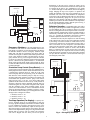
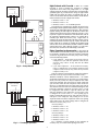
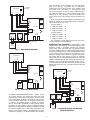
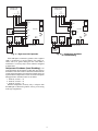
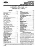
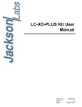
Aquazone™ Water Source Heat Pump Units
Deluxe D Electronic Controls
Application Data
TABLE OF CONTENTS
Page
GENERAL . . . . . . . . . . . . . . . . . . . . . . . . . . . . . . . . . . . . . . . . 1
APPLICATION . . . . . . . . . . . . . . . . . . . . . . . . . . . . . . . . . . 1-6
Dehumidification Control. . . . . . . . . . . . . . . . . . . . . . . . . 1
Electric Reheat Operation . . . . . . . . . . . . . . . . . . . . . . . . 2
Emergency Shutdown. . . . . . . . . . . . . . . . . . . . . . . . . . . . 3
Circulation Pump Control (Pump Restart) . . . . . . . . 3
Two-Stage Operation (Fan Staging) . . . . . . . . . . . . . . 3
Boilerless Operation . . . . . . . . . . . . . . . . . . . . . . . . . . . . . 3
Night Setback with Override. . . . . . . . . . . . . . . . . . . . . . 4
Relay Operation for Accessories . . . . . . . . . . . . . . . . . 4
• WATER CONTROL VALVE OPERATION
• OUTSIDE AIR DAMPER OPERATION
Night Low Limit Protection . . . . . . . . . . . . . . . . . . . . . . . 5
Compressor Shutdown (Load Shedding) . . . . . . . . . 6
GENERAL
Aquazone water source heat pump products are available
with two unit controller options, Complete C and Deluxe D.
Both include standard microprocessor-based technology to
ensure maximum reliability, extensive safety features, control
functions, and diagnostic abilities. The standard microprocessor control option, the Complete C, provides exceptional
control features including:
• Loss of charge switch
• High pressure switch
• Water and air coil freeze protection (selectable for water
or anti-freeze)
• Lockout safety circuit reset at thermostat or disconnect
• LED fault indication
• Five-minute anti short cycle
• Random start
• High and low voltage protection
• Condensate overflow protection
• Dry contact for alarm
• Accessory relay (for control valves, etc.)
• High and Low water temperature monitor
• Electric heat output controls
• 50 va transformer
The functionality of the standard Complete C unit controller
provides appropriate unit protection and operation to satisfy
most applications. However, some applications may require
additional features to further enhance the operation of the
individual water source heat pump unit or to enable integration
of units into a system control scheme. In these situations,
the Deluxe D control has advanced functionality beyond the
capabilities of the Complete C, including:
• Boilerless heat control
• Expanded LED display (i.e., separate test, fault, and
status indicators)
• Fan speed control options
• Configurable relays for multiple applications
• Communications port for dual compressor and slave
heat pump applications
• Accepts heat pump (Y, O) or heat/cool (Y, W) thermostat
types
• Accepts heat pump thermostats with O or B reversing
valve logic
• Emergency shutdown input
• Night setback feature
• Accessory relay options
• 75 va transformer
This application data elaborates on the specific features of
the Deluxe D board and how they enhance unit operation to
meet specific requirements (e.g. humidity control, two-stage
operation, accessory control, etc.) or help coordinate total
water source heat pump system integration (e.g., pump restart
coordination, emergency shutdown, night setback, etc.). The
Deluxe D controls allow many system features to be integrated
without implementing DDC (Direct Digital Control).
APPLICATION
Dehumidification Control — In certain applications
or climates, humidity control can be an essential part of a water
source heat pump system. To provide a solution for humidity
control on Aquazone units, Carrier has designed specially
integrated functionality into the Deluxe D control to maintain
room humidity levels. The dehumidification control for
Aquazone units provides a simple and effective option for
small capacity units at a relatively low cost compared to other
strategies, such as hot gas reheat.
When the Deluxe D unit controller option is specified or
provided with any direct driven Aquazone unit, the controller
automatically changes the fan speed to maintain room humidity levels. This feature is flexible and can be selected to meet
specific room sensible and latent room characteristics, since the
fan speed can be customized to operate on two of three available speeds (i.e., low, medium, or high by changing the taps).
The Deluxe D controller will automatically change the fan
speeds based on the humidity input connection located on the
controller (i.e., when used with a humidity sensing device
inside the room).
TM
Manufacturer reserves the right to discontinue, or change at any time, specifications or designs without notice and without incurring obligations.
PC 111
Catalog No. 515-00042
Printed in U.S.A.
Form 50R-1XA
Pg 1
7-03
Replaces: New
Book 1
Tab 5a
To assess the dehumidification moisture removal capability,
consider the following example. The greater the difference
between the indoor evaporator coil temperature and the return
air wet bulb, the greater the ability the coil has to remove
excess moisture. For a 3-ton 50RHR unit, at different fan
speeds, the performance is shown in Table 1.
opposed to switching to the higher speed as described above
for normal operation of the Deluxe D board). If the H input is
satisfied, the Y2 will operate normally and switch to the higher
speed. The unit will not overcool the room since it will turn off
when the space temperature is satisfied.
Table 1 — Humidity Removal for 50RHR036
at Various Fan Speeds
humidity control for Aquazone water source heat pumps is to
use the Deluxe D control board to maintain humidity levels
with electric reheat. The advantage of this method is that an
electric duct heater can be sized to match the exact amount of
sensible heat addition required to reduce the relative humidity.
See Fig. 2 for Deluxe D electric reheat operation wiring. In
order to use the Deluxe D board in this manner, the Deluxe D
board switches must be configured as follows:
1. Bank S2, switch 1 = off.
2. Bank S2, switch 2 = on.
3. Bank S2, switch 3 = off for cooling with reheat mode.
Under normal operation, this will operate the water source
heat pump unit as follows:
1. Standard cooling: Y1 and O inputs will turn on the
compressor, reversing valve and fan.
2. Standard heating: Y1 input will turn on the compressor
and fan.
The Accessory Relay no. 1 (ACC1) should be used as the
electric heat output. This is a pilot duty relay, which is a dry
contact. Simply connect this to the low voltage input of the
external electric heater to turn it on and off.
The Deluxe D control will provide just reheat or both
cooling and reheat together. The H input should be connected
to the humidistat, or whatever device is communicating that the
humidity is too high. This is a 24 vac input just like all of the
thermostat inputs (Y1, Y2, O, etc.). For reheat based on a
humidity call only, the humidistat and the H input will turn on
the compressor, reversing valve, fan, and accessory relay no. 1
(ACC1). For both cooling with reheat, H, Y1, and O inputs will
turn on the compressor, reversing valve, fan, and accessory
relay no. 1. For standard Heating (reheat disabled), H and Y1
inputs will turn on compressor and fan.
PERFORMANCE
Airflow (CFM)
Sensible (MBtuh)
Latent (MBtuh)
EER
CFM/ton
SHR
LAT (DB/WB)
Moisture Removed (gr/min)
DB
EAT
EER
EWT
LAT
MBtuh
SHR
WB
—
—
—
—
—
—
—
—
LOW
SPEED
932
22.6
10.5
12.7
311
0.68
57.5/55.3
1216
MEDIUM
SPEED
1200
25.5
8.7
12.7
400
0.75
60.3/57.8
1043
Electric Reheat Operation — Another approach to
HIGH
SPEED
1343
27.1
7.5
12.6
448
0.78
61.3/58.8
973
LEGEND
Dry Bulb
Entering Air Temperature
Energy Efficiency Ratio
Entering Water Temperature
Leaving Air Temperature
Btuh in Thousands
Sensible Heat Ratio
Wet Bulb
NOTES:
1. EAT = 80DB/67WB.
2. EWT = 3 gpm/ton.
As the example demonstrates, reducing the fan speed from
Medium to Low, or from High to Low speed results in the
following:
• Higher latent capacity removal.
• Slightly higher efficiency.
• 25% more moisture removal in low speed vs. high
speed.
• 17% more moisture removal in low speed vs. medium
speed.
Some additional system benefits for operation using fan
speed control include:
• Reduced sound levels at lower fan speeds.
• Increased filter performance at lower fan speeds.
• Ability to operate and select two fan speeds that closely
match room sensible and latent heat pick-up.
Fig. 1 illustrates dehumidification operation for a directly
driven Aquazone™ unit. In combination with unit wiring, the
Deluxe D DIP switch 7 on bank S2 must be turned to the “ON”
position.
The sequence of operation for this feature is as follows.
When the Deluxe D board is provided, the normal operation of
this unit controller (i.e., without using the dehumidification
feature) has the ability to control two stages of cooling operation (i.e., Y1 and Y2). Refer to page 3 for an explanation of
two-stage operation. In two stage operation, the 3-speed PCS
blower is only connected to two speeds at any one time
(i.e., Med and High, Med and Low, Low and High). Under
normal operation using the Deluxe D board, on a call for Y1,
the lower of the two speeds connected will operate, and on a
call for Y2 the higher of the two speeds connected will operate.
When the H input is used on the Deluxe D board, and the
DIP switch 7 on block S2 is turned on to operate in dehumidification fan speed mode, if there is a call for the Y2 stage, the
lower fan speed connected will not switch to the higher speed
in order to reduce and satisfy the H input humidity level (i.e., as
50QE900 AQUAZONE
THERMOSTAT
C
R
B
O
G W1
Y1
Y1
Y2
O/W2
G
R
C
HUMIDISTAT
H
R
FAN
ENABLE
FAN
SPEED
DELUXE D
LEDS
TEST
S1
S2
Fig. 1 — Dehumidification Operation
2
Performance of the unit can be selected to operate on any
two-fan speeds to meet the actual room heat rise. Fan speeds can
be switched in the field to any combination of two speeds
(i.e., medium and high, low and medium, and low and high) by
simply changing the taps. The sequence of operation will
include the initiation of the lower speed connected on an Y1
thermostat call. If the unit cannot maintain the temperature
levels in the room, the thermostat will send a Y2 call to the unit,
which will automatically upstage the fan speed to the next
highest level. For example, if the unit was initially operating on
medium speed and the unit cannot maintain room temperature,
the unit will automatically switch to high fan speed. See Fig. 5
for two-stage wiring diagram operation.
50QE900 AQUAZONE
THERMOSTAT
C
R
B
O
G W1
Y1
Y1
Y2
O/W2
G
R
C
H
R
HUMIDISTAT
NO1
COM
ELECTRIC
HEATER
FAN
ENABLE
FAN
SPEED
Boilerless Operation — Depending on the water source
heat pump system design and climate for application, a boiler
for heat addition may not be required or desired. In systems
that are not designed with a boiler, Aquazone units can accommodate boilerless operation where electric resistance heating is
automatically controlled when the water temperature is below
50 F (i.e., typically the temperature when boiler operation
would be required to add heat to the system water loop).
In boilerless mode, only the compressor is used for heating
mode when the FP1 sensor is above the temperature specified
by the setting of switch 8 on bank S1. If this switch is set for
50 F, then the compressor is used for heating as long as FP1 is
above 50 F. Below 50 F, the compressor is not used and the
control goes into Emergency Heat mode, where outputs EH1
and EH2 are initiated to control an electric duct mounted
heater. If a thermal switch is being used in place of the HP1
thermistor, then only the compressor will be used for heating
mode when the FP1 terminals are closed. If the HP1 terminals
are open, then the compressor is not used and the control goes
into Emergency Heat mode.
DELUXE D
LEDS
ACC1
RELAY TEST
S1
S2
Fig. 2 — Electric Reheat
Emergency Shutdown — In some applications, it may
be desirable to shut down all of the individual water source
heat pumps. For example, in a fire alarm situation. The Deluxe
D controller includes a built in emergency shutdown input
(ESD) that will shut the Aquazone™ unit down when an
external control signal is connected. Individual Aquazone units
can be “daisy chained” together to all shut down in an emergency situation. See Fig. 3 for wiring the Deluxe D controller
to operate for emergency shutdown operation. When the ESD
input is connected to the ground terminal C, all thermostat
inputs will be ignored and all outputs will be turned off. There
is a built in random start timer when individual units turn back
on from ESD mode.
50QE900 AQUAZONE
TO OTHER
UNITS
THERMOSTAT
C
Circulation Pump Control (Pump Restart) — In
a typical water source heat pump system, the centralized circulation pumps that deliver water to all the individual units are in
a constant flow operation. However, when all of the water
source heat pump units are not operating, it may be desirable to
shut down the main circulation pumps to help save energy
associated with pump operation. The Deluxe D controller can
accommodate this operation with the pump restart feature
using accessory relay 2. See Fig. 4 for wiring pump restart
operation and the location of the accessory 2 relay. Similar to
emergency shut down wiring, individual Aquazone units are
connected together in a daisy chain arrangement and coupled
with the operation of the main circulation pumps for the
system. The COM terminal is used to communicate external
signals to subsequent Deluxe D controllers. In order to configure the Deluxe D board in this type of arrangement the switch
settings must be configured as follows:
1. Bank S2, switch 4 = on
2. Bank S2, switch 5 = on
3. Bank S2, switch 6 = on
R
B
O
G W1 Y1
Y1
O/W2
G
R
C
FAN
ENABLE
FAN
SPEED
ESD
C
DELUXE D
LEDS
TEST
S1
FIRE
ALARM
S2
FAN
ENABLE
DAISY CHAIN
ARRANGEMENT
FAN
SPEED
Two-Stage Operation (Fan Staging) — Capacity con-
ESD
C
trol for Aquazone units can be implemented by using the
two-stage operation capability of the Deluxe D control to adjust
to room conditions. The built in microprocessor logic of the
Deluxe D board will automatically adjust the fan speed for
direct driven units to provide capacity control of the unit. This
feature can be implemented by using a two-stage thermostat that
includes both Y1 and Y2 calls for cooling. The Aquazone
unit will be shipped from the factory on two fan speeds.
DELUXE D
LEDS
TEST
TO OTHER
UNITS
S1
S2
Fig. 3 — Emergency Shutdown
3
Night Setback with Override — When an external
PUMP
RESTART
INPUT
50QE900 AQUAZONE
timeclock is used to schedule the operation of multiple
Aquazone™ water source heat pumps units (i.e., for night
setback operation), the Deluxe D board can be used to handle a
grounded signal. Fig. 6 illustrates the wiring for night setback
(NSB) with the Deluxe D board to accomplish this task. In
order to use the Deluxe D board in this manner, first the Deluxe
D board switches must be configured as follows:
1. Bank S2, switch 1 = off
2. Bank S2, switch 2 = on
3. Bank S2, switch 3 = on for NSB operation.
The timeclock is programmed to schedule the units for the
desired night setback operation and distributes a signal to several
Aquazone units. Individual Aquazone units are “daisy chained”
together utilizing the NSB input into the Deluxe D board. The
signal from the timeclock is used to initiate the accessory 1 relay
to provide a signal to the thermostat. Some thermostats, such as
the Aquazone 50QE900-250FS, contain a dry contact that is
normally open. When the accessory relay 1 signal closes or
completes the circuit, the thermostat will enter occupied 1 mode.
If the thermostat has an isolated type dry contact, the Deluxe D
board would not be required for isolating the grounded signal
from the time clock. The maximum number of Deluxe D board
controls that can be “daisy chained” together is 75. The maximum total wire resistance of the NSB wiring is 500 ohms.
THERMOSTAT
C
R
B
O
G W1 Y1
Y1
O/W2
G
R
C
FAN
ENABLE
FAN
SPEED
NO.2
COM
ACC2
RELAY
LEDS
TEST
S1
S2
FAN
ENABLE
FAN
SPEED
NO.2
COM
ACC2
RELAY
Relay Operation for Accessories — The Deluxe D
control includes two individual accessory relay outputs that can
be specifically configured to control the operation of different
accessories. In general, the two accessory relays can be configured in the following manner:
1. Cycle with Fan — If one of the two accessory relays is
configured to cycle with the operation of the fan, the
accessory relay will be on any time the fan enable
relay is on.
2. Cycle with Compressor — If one of the two accessory
relays is configured to cycle with the operation of the
compressor, the accessory relay will be on any time the
compressor relay is on.
There are certain accessories that may require the configuration of the accessory relays for either one of these modes.
WATER CONTROL VALVE OPERATION — In variable
speed pump applications or for open loop type system arrangements, a two-way control valve may be required at each water
source heat pump unit. The control valve is usually required to
open and close when the unit compressor turns on and off.
However, it is desirable to have the water control valve turn on
first such that water flow has been established through the unit
before the compressor is turned on. Accessory relay 1 or 2 can
be configured in this manner to open the control valve and
delay the initiation of the compressor. If an accessory relay
is configured for a water valve (i.e., a slow opening type is
usually recommended) the accessory relay will turn on 60 seconds prior to the compressor relay turning on. To use the
Aquazone Deluxe D board in conjunction with a slow opening
water control valve, the switch settings must be configured as
follows for accessory relay 1 or 2:
Accessory Relay 1:
1. Bank S2, switch 1 = on
2. Bank S2, switch 2 = on
3. Bank S2, switch 3 = on
Accessory Relay 2:
1. Bank S2, switch 1 = on
2. Bank S2, switch 2 = on
3. Bank S2, switch 3 = on
Fig. 7 illustrates a wiring diagram for the utilization of
accessory relay 1 to control a slow opening water valve.
LEDS
TEST
S1
TO OTHER
UNITS
S2
Fig. 4 — Pump Restart
50QE900 AQUAZONE
THERMOSTAT
C
R
B
O
G W1 Y2 Y1
Y1
Y2
O/W2
G
R
C
FAN
ENABLE
FAN
SPEED
DELUXE D
LEDS
TEST
S1
S2
Fig. 5 — Two-Stage Operation
4
relay will not turn on for 30 minutes even if the fan enable
relay is on. This type of operation may be desirable to
condition the space to desired levels in the morning, when
space loads are at a maximum (i.e., since units have been
turned off at night-time to conserve energy) without having to
also condition outdoor air (i.e., since occupancy loads will be
minimal in the early morning). After the 30-minute timer
expires, the accessory relay will turn on if the fan enable relay
is on.
To use the Aquazone Deluxe D board in conjunction with a
outside air damper, the switch settings must be configured as
follows for accessory relay 1 or 2:
Accessory Relay 1:
1. Bank S2, switch 1 = on
2. Bank S2, switch 2 = on
3. Bank S2, switch 3 = off
Accessory Relay 2:
1. Bank S2, switch 1 = on
2. Bank S2, switch 2 = on
3. Bank S2, switch 3 = off
Fig. 8 illustrates a wiring diagram for the use of accessory
relay 2 to control an outside air damper.
50QE900-250FS AQUAZONE
OVERRIDE
BUTTON
THERMOSTAT
C
GND CK1
B
O
G W1 Y1
R
Y1
Y2
W1
O/W2
G
R
C
FAN
ENABLE
FAN
SPEED
DELUXE D
LEDS
NC1
COM
OTHER
DELUXE D
NSB
OTHER
DELUXE D
C
NSB
ACC1
RELAY
NSB
C
TEST
C
S1
S2
TO MORE UNITS
WITH DELUXE D
Night Low Limit Protection — Functionality is built
into the Deluxe D controller to accommodate night low limit
protection, which is specifically intended for Aquazone
console water source heat pump units. An application where
this feature might be used is in a hotel/motel building. When a
room is not occupied for short or long extended periods of time
(e.g. in between guests) a unit may not be required to provide
heating or cooling. In these situations, night low limit protection ensures that the room will not get cold. All Aquazone
console units that are provided with the Deluxe D control will
include a standard night low limit switch in the air return to the
unit that is set for 55 F. When the temperature in the room (i.e.,
or in the return of the unit) decreases below this limit, the unit
heating will turn on. See Fig. 9 for night low limit wiring and
application.
TIME
CLOCK
Fig. 6 — Night Setback Operation
50QE900 AQUAZONE
THERMOSTAT
C
R
B
O
G W1
Y1
Y1
Y2
O/W2
G
R
C
FAN
ENABLE
50QE900-250FS AQUAZONE
THERMOSTAT
FAN
SPEED
DELUXE D
GND CK1
LEDS
NO1
COM
WATER
VALVE
C
R
OVERRIDE
BUTTON
B
O
G W1 Y1
ACC1
RELAY TEST
S1
Y1
Y2
W1
O/W2
G
R
C
S2
Fig. 7 — Accessory Relay Wiring
FAN
ENABLE
FAN
SPEED
DELUXE D
LEDS
NC1 ACC1
COM RELAY
OTHER
DELUXE D
OUTSIDE AIR DAMPER OPERATION — When outside
air is directly ducted to each Aquazone™ water source heat
pump unit, one of the accessory relays can be used to open and
close a local outside air damper. The accessory relay will turn
on any time the fan enable relay is on. Using an accessory relay
to control a two-position damper is flexible for morning
start-up, when indoor conditioning is desired without tempering outdoor air. This feature is used in conjunction with the
NSB input to accommodate the operation of multiple units that
are connected together with a “daisy chain” arrangement. Following a return from the NSB (i.e., the NSB input is no longer
connected to ground C), to normal operation, the accessory
NSB
C
OTHER
DELUXE D
NSB
C
DAMPER
NC2 ACC2
COM RELAY
NSB
C
TEST
S1
S2
TO MORE UNITS
WITH DELUXE D
TIME
CLOCK
Fig. 8 — Outside-Air Damper with Morning
Warm-Up Operation
5
50QE900-250FS AQUAZONE
THERMOSTAT OR
UNIT MOUNTED
C
R
50QE900 AQUAZONE
THERMOSTAT OR
UNIT MOUNTED
B
O
G W1 Y1
Y1
O/W2
G
R
C
NLL
SWITCH
55 F
SETPOINT
OVR
NSB
C
OTHER
DELUXE D
FAN
SPEED
NSB
FAN
SPEED
NC1
ACC1
COM RELAY
LEDS
TEST
OTHER
DELUXE D
C
S1
FAN
ENABLE
DELUXE D
DELUXE D
NSB
C
R
R
C
O/W2
G
Y1
FAN
ENABLE
R
OTHER
DELUXE D
B
O
G W1 C
Y1
NSB
S2
OTHER
DELUXE D
C
NSB
NSB
C
LEDS
TEST
C
S1
TO MORE UNITS
WITH DELUXE D
S2
TO MORE UNITS
WITH DELUXE D
COMPRESSOR
SHUTDOWN
SIGNAL
TIME
CLOCK
Fig. 10 — Compressor Shutdown
for Load Shedding
Fig. 9 — Night Low Limit Operation
If the NSB input is connected to ground C, then a signal at
OVR is recognized as a call for heating. Also, inputs Y1,
O/W2, and G are ignored during the time when NSB is
connected to C. Accessory relays 1 and 2 cannot be configured
as digital NSB.
Compressor Shutdown (Load Shedding) — In
some applications, the local utility or other entity may desire to
shut down several units in order to shed electrical load from the
system grid. In this instance, the Deluxe D controller can be set
up to shut down multiple units to reduce electrical consumption
during peak times. Switches must be set as follows:
1. Bank S2, switch 1 = on
2. Bank S2, switch 2 = on
3. Bank S2, switch 3 = on
With this configuration, accessory relay 1 will open when
the NSB input is connected to ground C. See Fig. 10 for wiring
in this type of application.
6
Copyright 2003 Carrier Corporation
Manufacturer reserves the right to discontinue, or change at any time, specifications or designs without notice and without incurring obligations.
PC 111
Catalog No. 515-00042
Printed in U.S.A.
Form 50R-1XA
Pg 8
7-03
Replaces: New
Book 1
Tab 5a