1
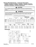
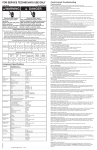
Service Specifications Side-by-Side RefrigeratorTechnical Information ! WARNING To avoid risk of electrical shock that can cause death or severe personal injury, disconnect unit from power before servicing unless tests require power. Discharge capacitors through a 10,000-ohm resistor before handling. Wires removed during disassembly must be replaced on correct terminals to ensure proper grounding and polarization. 3. Release the refrigerator door light switch. 4. The control will display Fd to confirm entry into the Forced Defrost Mode. Freezer ASD2626HEB ASD2626HES ASD2628HEB ASD2628HES ASD2626HEB0, ASD2626HEQ ASD2626HES0, ASD2626HEW ASD2628HEB0, ASD2628HEQ ASD2628HES0, ASD2628HEW Due to a possibility of personal injury or property damage, always contact an authorized technician for service or repair of this refrigerator. ! Refrigerator F CAUTION All safety information must be followed as provided in Service Manual 16022689. key once more. The unit is off and in the Defrost Mode. 5. Entry is confirmed by pressing the Refrigerator Down Note: All control functions will be turned off (Compressor, Defrost, Evaporator Fan, the damper will remain in its current position) 6. The control will default to the short run period test as shown here Freezer Refrigerator S Note: You can toggle between the (S)hort and (L)ong test mode by pressing the Refrigerator UP Long Test mode is used for factory test and should not be used in the field. Freezer Key. ! Refrigerator down Key once. 7. Once the desired mode is displayed, confirm the forced defrost by pressing the Refrigerator The defrost will begin immediately and the display will return to a normal operating display with set point values. Freezer Refrigerator 4 4 Kw/24 hr ±0.4 Ambient °F 26 cu ft Service Test Mode: 1. Hold the refrigerator door light switch closed. 70° 1.2 90° 1.85 110° 2.6 No-Load Performance, Controls in Normal Position Refrigerator Center Compartment Percent Run Time Average Food Cycles/24 hr ±10% Temperature ±3°F ±25% 70° 35 90° 55 110° 75 70° 24 90° 24 110° 19 70° 37 90° 39 110° 42 Freezer Compartment Average Food Temperature ±3°F 70° 0 90° 0 110° -2 Temperature Relationship Test Chart 8. Close the Refrigerator door(s). You are in the defrost mode Note: Forced Defrost mode can be exited at any time prior to step 7 by closing the Refrigerator Door(s). The service test functions are performed using the refrigerator display and keypad. Enter the Service Test Mode by performing the following sequence of events WARNING To avoid risk of electrical shock that can cause death or severe personal injury, disconnect unit from power before servicing unless testing is required. Discharge capacitors through a 10,000 ohm resistor before handling. Wires removed during disassembly must be replaced on correct terminals to ensure proper grounding and polarization. L 2. Press the Refrigerator Temperature Up ASD2626HEQ0, ASD2626HEW0, ASD2628HEQ0, ASD2628HEW0 Ambient °F 26 cu ft Evaporator Outlet ±3°F 70° 90° -15 -15 Evaporator Inlet ±3°F 70° 90° -16 -16 Suction Line ±7°F 70° 72 90° 98 Average Total Wattage ±10% 70° 132 90° 138 Suction Pressure ±2 PSIG 70° 6"(Vac.) 90° 0 Head Pressure ± 5 PSIG 70° 87 Schematic keypad 3 times consecutively. Note: The 3 Keystrokes must be done consecutively and within 10 seconds. 3. Release the refrigerator door light switch. 4. The control will display SE to confirm entry into the service mode. Freezer Refrigerator E S 5. Entry to the Service Menu is confirmed by pressing the Refrigerator Up 6. The control will display its software version for 3 seconds. Freezer key once more. Refrigerator 2 5 7. Following the software revision display the freezer display will read the first test number in the diagnostic tree. The refrigerator display will be blank Freezer Refrigerator 1 Note: All control functions will be turned off (Compressor, Defrost, Evaporator Fan, the damper will remain in its current position) 8. You are now in the SERVICES TEST operational mode and may use the diagnostic tests The Service Test Mode can be exited at any time by closing the Refrigerator Door(s). April 2004 © 2004 Maytag Services 4 16023095 April 2004 © 2004 Maytag Services 1 16023095 90° 137 Component Specifications ! Service Specifications ! WARNING To avoid risk of electrical shock that can cause death or severe personal injury, disconnect unit from power before servicing unless tests require power. Discharge capacitors through a 10,000-ohm resistor before handling. Wires removed during disassembly must be replaced on correct terminals to ensure proper grounding and polarization. WARNING To avoid risk of electrical shock that can cause death or severe personal injury, disconnect unit from power before servicing unless tests require power. Discharge capacitors through a 10,000-ohm resistor before handling. Wires removed during disassembly must be replaced on correct terminals to ensure proper grounding and polarization. Programming Mode: Component Specifications all parts 115VAC/60HZ unless noted Compressor run capacitor Volt ..................................................... Capacitance ...................................... Compressor BTUH ................................................. Watt ................................................... Current Lock rotor .............................. Current Full load ................................ Resistance Run windings................... Resistance Start windings.................. 220 VAC 15 µfd ± 10% 905 BTUH 60 Hz / 153 watts 19.0 amps± 15% 1.26 amps± 15% 3.33 ohms± 15% 4.28 ohms± 15% Electric damper control Maximum closing time Temperature Rating RPM 36 seconds 20°F- 110°F 1 Thermistor Temperature 77°F.................................................... 36°F ................................................... 0°F...................................................... Resistance 10,000 ohms± 1.8% 29,500 ohms± 1.0% 86,300 ohms± 1.8% Rotation (facing end opposite shaft) RPM Watt.................................................... Current ............................................... Clockwise 1250 RPM 4.2 watts±15%@115VAC 0.63 amps± 15%@115VAC Rotation (facing end opposite shaft) RPM…………………………………… Watt……………………………………. Note: Fan blade must be fully seated on shaft to achieve proper airflow. Clockwise 2800 RPM 5.9 ±15% watts@115VAC Overload/Relay Ult. trip amps @ 158°F (70°C) ........... Close temperature ........................... Open temperature ............................ Short time trip (seconds).................... Short time trip (amps @77°F (25°C) .. 2.67 amps± 15% 142°F ±9°F 284°F ±9°F 10 seconds ±5 11 amps ±2amps Thermostat (Defrost) Volt .................................................... Watt ................................................... Current ............................................... Resistance across terminals: Above 42°F ±5°.................................. Below 12°F ±7° .................................. Volt..................................................... Wattage.............................................. Resistance ......................................... 120/240 VAC 495 watts 5.8/2.9 amps Control board Volt..................................................... 120VAC, 60 HZ See Control board troubleshooting section Auger Motor Rotation (facing end opposite shaft) Water Valve (Primary) Water Valve (Secondary) Light switch RPM ................................................... Watts Watts Type…………………………………….. Volt……………………………………… Current………………………………….. Power to blue and white is clockwise. Power to orange and white is counterclockwise 17± 3 RPM Brown side 35w,Yellow side 20w Brown side 35w,Yellow side 20w SPST NC 125/250 VAC 8/4 amps Type…………………………………….. Volt……………………………………… Current………………………………….. Resistance across leads .................... SPDT NO/NC 125/250 VAC 8/4 amps 101ohms ± 10% Condenser motor Evaporator fan motor Evaporator heater Light switch / Interlock Solenoid (Ice Chute) April 2004 © 2004 Maytag Services Note: The Program Code is located on the Serial Plate on this unit after the word Code. 1. Open the Fresh Food door and hold the Fresh Food door light switch closed while pushing the Freezer Temperature Down Key pad 3 times consecutively. Note: The 3 Keystrokes must be done consecutively and within 10 seconds. 2. Release the Fresh Food door light switch. 3. The control will display PE to confirm entry into the programming mode. Freezer P 4. Entry is confirmed by pressing the Freezer Down E key once more. Note: All control functions will be turned off (Compressor, Defrost, Evaporator Fan, the damper will remain in its current position) 5. The control will display the current Program Code. This value should be validated with the Program Code printed on the unit serial plate. Freezer 2 Refrigerator 5 Note: If the Program Code is correct, the Programming Mode is exited by closing the Refrigerator door(s). 6. To set the desired Program Code number press the Freezer and Refrigerator UP keys. The corresponding digit will be advanced with each key press. 7. Once the desired Program Code is displayed, press the Freezer DOWN Key until the Program Code begins flashing indicating it has been saved. Note: If you attempt to enter an invalid Program Code the control will not save the new code, but will flash the old code and this will be displayed. (The unit will NOT run with a Program Code of 00). 8. Once the Program Code has been saved the Programming Mode is exited by closing the Refrigerator door(s). If the new code is incorrect this process should be repeated after closing the Refrigerator door(s). The Programming mode can be exited at any time by closing the Refrigerator Door(s). Open Closed 115 VAC 450 ±5% watts @ 115VAC 29 ±7.5% ohms 2 Refrigerator Defrost Operation: The Control Board adapts the compressor run time between defrosts to achieve optimum defrost intervals by monitoring the length of time the defrost heater is on. After initial power up, defrost interval is 4 hours compressor run time. Defrost occurs immediately after the 4 hours. Note: Once unit is ready to defrost there is a 4 minute wait time prior to the beginning of the defrost cycle. Optimum defrost is 15 minutes. Each additional minute the defrost thermostat remains closed, 1 hr. is subtracted from the previous defrost interval. Each minute the thermostat opens prior to optimum defrost, it extends the next defrost interval 1 hr. When defrost thermostat opens there is a 4-6 minute drip time before compressor restarts or Control Board will terminate defrost at 25 minutes if defrost thermostat has not opened and will reset the defrost interval to the 8 hr. minimum setting. 4 hours of continuous compressor run resets the next defrost interval to 8 hours and will initiate a defrost, if 8 hours of compressor run time has also occurred. Forced Defrost Mode: Power up Refrigeration mode will occur unless both the cold control and defrost terminator are open, in that case the defrost mode will occur for 2 minutes. The forced defrost function is performed using the refrigerator display and keypad. Enter the Forced Defrost Mode by performing the following sequence of events: 16023095 1. Hold the refrigerator door light switch closed. keypad 3 times consecutively. 2. Press the Refrigerator Temperature Down Note: The 3 keystrokes must be consecutive and within 10 seconds. April 2004 3 © 2004 Maytag Services 16023095 Wiring Diagram Service Specifications ! ! WARNING To avoid risk of electrical shock that can cause death or severe personal injury, disconnect unit from power before servicing unless tests require power. Discharge capacitors through a 10,000-ohm resistor before handling. Wires removed during disassembly must be replaced on correct terminals to ensure proper grounding and polarization. WARNING To avoid risk of electrical shock that can cause death or severe personal injury, disconnect unit from power before servicing unless tests require power. Discharge capacitors through a 10,000-ohm resistor before handling. Wires removed during disassembly must be replaced on correct terminals to ensure proper grounding and polarization. Service Test 1 – Defrost Thermostat & Defrost Circuit Test When selected this test will display the state of the defrost thermostat. In order to perform this test the defrost heater will be energized. The test is activated and deactivated using the Refrigerator Up key. Once activated, this test must be de-activated to move to another test number. The Freezer Up / Down keys allow selection of the test to be performed. This test also allows observation and measurement of proper defrost function. You can observe defrost heat and voltages while the test is activated. Freezer Refrigerator O 1 DEFROST THERMOSTAT OPEN Freezer Refrigerator 1 S DEFROST THERMOSTAT SHORTED (CLOSED) Service Test 2 – Compressor/Condenser Fan Test When selected and activated this test will operate the Compressor/Condenser Fan circuit. You should evaluate proper operation of the compressor and condenser fan. The Refrigerator Up key will toggle between “O” / “F” (ON & OFF) the compressor drive circuit. The test must be “deactivated” or in the OFF position to move to another test selection. Freezer Refrigerator 2 O Freezer Refrigerator 2 F OBSERVE COMPRESSOR & CONDENSER FAN FUNCTION Service Test 3 – Evaporator/Freezer Fan Test When selected and activated this test will operate the freezer fan. The Refrigerator Up key will toggle between “O” / “F” (ON & OFF) the fan drive circuit. You will have to inspect the fan for proper function. The test must be “deactivated” or in the OFF position to move to another test selection. Refrigerator Freezer O 3 Freezer Refrigerator 3 F OBSERVE FAN OPERATION April 2004 © 2004 Maytag Services 8 16023095 April 2004 © 2004 Maytag Services 5 16023095 Service Specifications Service Specifications ! ! WARNING To avoid risk of electrical shock that can cause death or severe personal injury, disconnect unit from power before servicing unless tests require power. Discharge capacitors through a 10,000-ohm resistor before handling. Wires removed during disassembly must be replaced on correct terminals to ensure proper grounding and polarization. WARNING To avoid risk of electrical shock that can cause death or severe personal injury, disconnect unit from power before servicing unless tests require power. Discharge capacitors through a 10,000-ohm resistor before handling. Wires removed during disassembly must be replaced on correct terminals to ensure proper grounding and polarization. Service Test 6 – Open Damper Test Service Test 4 – Fresh Food Thermistor Test When selected and activated this test will display Pass, Open, Short result for a test on the Fresh Food Thermistor circuit as show below. The test is activated and de-activated via the Refrigerator Up key, and must be de-activated to move to another test selection. Freezer When selected this test will indicate the current position “O” / “C” (OPEN / CLOSED) of the refrigerator damper. The Refrigerator Up key will toggle the damper open and closed. You must allow 1 minute for each attempt to change the damper position. You should observe proper damper function. Freezer 6 Refrigerator 4 P ! CAUTION Adjustments of Service Test 7 or Service Test 8 will alter the performance of the unit. OPEN RESULT Service Test 7 – FF Performance Adjustment Refrigerator 4 This test will allow adjustment of the control performance points. Each step will incrementally change the Refrigerator performance warmer (towards 1) or colder towards (9) as adjusted. The default value is 5. S The refrigerator / Up/Down keys are used to adjust the Performance Offset value. WARMER Í(1 2 3 4 (5) 6 7 8 9) Î COLDER. SHORT RESULT Freezer Service Test 5 – Freezer Thermistor Test DEFAULT Service Test 8 – FZ Performance Adjustment This test will allow the adjustment of the control performance points. Each step will incrementally change the Freezer performance warmer (towards 1) or colder towards (9) as adjusted. The default value is 5. The refrigerator / Up/Down keys are used to adjust the Performance Offset value. WARMER Í(1 2 3 4 (5) 6 7 8 9) Î COLDER Refrigerator O Freezer OPEN RESULT Freezer Refrigerator 5 8 Refrigerator 5 6 COLDER The last FF Performance Offset value displayed before leaving test 7 will be saved when the refrigerator door(s) is closed. PASS RESULT 5 Refrigerator 7 P Freezer 5 Freezer Refrigerator 5 Refrigerator 7 When selected this test will display Pass, Open, Short result for a test on the Freezer Thermistor circuit as show below. The test is activated and de-activated via the Refrigerator Up key, and must be de-activated to move to another test selection. Freezer C OBSERVE DAMPER FUNCTION O Freezer Refrigerator 6 Refrigerator 4 O Freezer PASS RESULT Freezer Refrigerator S DEFAULT Freezer SHORT RESULT Refrigerator 8 4 WARMER The last FZ Performance Offset value displayed before leaving test 8 will be saved when the refrigerator door(s) is closed. April 2004 © 2004 Maytag Services 6 16023095 April 2004 © 2004 Maytag Services 7 16023095