1
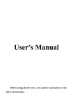
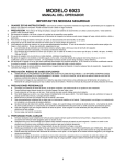
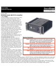
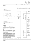
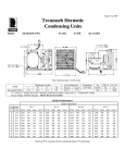
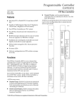
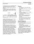
1
Discrete Output Modules
IC697MDL940
56
Relay Output, 16 Point Module
GFK-0384E
August 1997
]]]Relay Output, 16 Point Module (IC697MDL940)
datasheet GFK-0384E
Features
a44323
D 16 points - 8 isolated Form C
- 2 groups of 4 Form A
D
D
D
D
A1
A2
A3
A4
A5
A6
A7
A8
2 amp per point switching capacity
RC snubber and fuse protection per point
No user power required
B1
B2
B3
B4
B5
B6
B7
B8
C1
C2
C3
C4
C5
C6
C7
C8
FUSE
Removable field wiring terminal
OUTPUT
RELAY, 16PT
2A PILOT DUTY
16A MAX/MODULE
A1
Functions
The 16 point Relay Output Module is versatile,
rugged, and easy to use. It will switch a variety of
low to medium power loads such as relays, contactors,
and lamps.
The resistive rating of the module is 2 amps per point
at 120/240 VAC or 24 VDC and 0.2 amps per point for
125 VDC. Power to energize the relay coils is supplied
by the module and each output is individually fused
and suppressed with an RC snubber.
A2
A3
A4
B1
B2
B3
B4
LED indicators which display the ON - OFF status of
each point on the logic (PLC) side of the circuit are
located at the top of the module.
C1
Field wiring is made to a removable terminal board
and the module is mechanically keyed to ensure correct replacement with a similar module type in the
field. I/O references are user configurable without the
use of jumpers or DIP switches on the module.
C3
C2
C4
D1
D2
Configuration is done using the configuration function of the MS-DOSr or Windowsrprogramming software running on Windowsr 95 or Windows NTr over
Ethernet TCP/IP or through the SNP port. The Programming Software configuration function is installed
on the programming device. The programming device can be an IBMr XT, AT,PS/2r or compatible Personal Computer.
D3
D4
SLOT
Î
Î
Î
Î
Î
Î
Î
Î
Î
Î
Î
Î
Î
Î
Î
Î
Î
Î
Î
Î
Î
Î
Î
Î
Î
Î
ÎÎ
Î
D1
D2
D3
D4
D5
D6
D7
D8
A1
A2
A3
A4
A5
A6
A7
A8
C1
B1
C2
B2
C3
B3
C4
B4
C5
B5
C6
B6
C7
B7
C8
B8
FUSE
D1
D2
D3
D4
D5
D6
D7
D8
24-240VAC 50/60HZ
5-125VDC
480VA, 60 WATT
NO A1
1
V
2
3
NC
A1
NO
4
5
6
7
A2
V
NC
NO
A3
NC
A3
A2
V
8
9
NO
10
11
A4
V
NC
12
A4
13
NO
14
15
B1
V
17
NC
NO
B2
19
NC
B2
16
B1
18
V
NO
20
21
22
23
B3
V
NC
NO
B3
B4
24
V
25 NC
B4
26
27
NO
28
29
NO
31
NO
NO
30
C1
C2
C3
C4
32
V
33
34
35
NO
36
38
NO
37 NO
NO
D1
D2
D3
D4
39
40
V
MODULE IC697MDL940
LABEL 44A726758-016RO3
r IBM and PS/2 are registered trademarks of International Business Machines Corporation.
r MS-DOS, Windows, Windows 95, and Windows NT are registered trademarks of Microsoft Corporation.
t
Series 90 -70 Programmable Controller Data Sheet Manual
GFK-0600F
56-1
Discrete Output Modules
2
GFK-0384E
August 1997
Relay Output, 16 Point Module
Operation - Relay Output Module
a44515
LED
FORM
C
RELAY
RELAY
DRIVER
BACKPLANE
SNUBBER
FORM
A
RELAY
V
FUSE 3A
SYSTEM
INTERFACE
RELAY
DRIVER
Î ÎÎ
NO
SNUBBER
Î
ÎÎ
Î ÎÎ
NC
NO
FUSE 3A
V
LED
Figure 1. Block Diagram for IC697MDL940
Output Protection
For more detailed information on module configuration,
refer to the Programming Software User’s Manual.
Fusing
Each output is protected with a 3 amp fuse. Replace
with either of the following types:
D 3AG - 3.0 amp, 250V, Fast Acting
D Metric 5 x 20 mm - 3.0 amp, 250V, Fast Acting
Suppression
Each output is suppressed with an RC snubber to reduce high frequency noise transients on the board.
Proper suppression of the switched load is still recommended and will contribute to improved system reliability. Suppression at the load will not only lengthen contact life, but will also reduce noise transients in the control
wiring.
Fault Mode Selection
This output module can be configured from the programmer so that output points assume one of two
states in response to certain operating or default
conditions. These states are:
D Maintain existing output state
D Turn outputs OFF
56-2
Module Mechanical Keying
This module includes a mechanical key that prevents
inadvertent substitution of one module type for
another in a given slot. The key fits a uniquely
shaped area on the board below the connector. Each
module has a key packaged with it.
When the module is first installed, the key latches
onto the backplane center rail. When the module is
extracted, the key remains in the center rail, configuring the slot to accept only identical module types.
If it is necessary to change the module location in the
rack after the key has been latched onto the center rail
of the rack, the key can be removed by pushing it upward to unhook the latch while pulling it off the rail.
It may then be reinserted onto the module and the
module inserted into the rack in the desired location.
Note that on;y a power supply can be placed in the
leftmost rack position, and slot 1 (adjacent to the power supply) must always contain a CPU (in rack 0 - the
CPU rack), or a Bus Receiver Module (in an expansion
rack).
t
Series 90 -70 Programmable Controller Data Sheet Manual
GFK-0600F
Discrete Output Modules
3
GFK-0384E
August 1997
Relay Output, 16 Point Module
Field Wiring
The module is wired as shown in Figure 2. You have
the choice of selecting either a normally open or a
normally closed relay contact (or both) for each of the
eight Form C relays, and four normally open contacts
for each group of Form A relays. A connection is provided at the V terminal for a power source for the
load. Each Form C relay and each group of the Form
A relays can switch either an AC or a DC load.
The detachable field wiring terminal board will accept
wire sizes from AWG #22 (0.36 mm2) through AWG
#14 (2.1mm2). Two wires may be terminated on a
given lug if both wires are the same size. There is
room for a bundle of forty #14 wires to be routed out
through the terminal board cavity.
The wire bundle can be secured to the terminal board
by passing a cable tie through a cleat located at the
lower corner of the terminal board.
TERMINALS
FIELD WIRING
a44324
1
NO
A1
NC
A1
2
V
3
NO
4
5
6
7
A2
V
NC
NO
A3
NC
A3
A2
V
8
9
NO
10
11
12
A4
V
NC
A4
NO
B1
13
14
15
16
17
V
NC
NO
B2
NC
B2
B1
18
19
V
NO
20
21
22
23
B3
V
NC
NO
B4
NC
B4
B3
24
V
25
26
27
NO
28
29
NO
C1
C2
NO
30
31
NO
C3
C4
32
V
33
34
35
NO
NO
36
37
NO
NO
38
D1
D2
D3
D4
39
40
V
Figure 2. Field Wiring Connections
t
Series 90 -70 Programmable Controller Data Sheet Manual
GFK-0600F
56-3
Discrete Output Modules
4
GFK-0384E
August 1997
Relay Output, 16 Point Module
Recommended Field Wiring Procedures
The following procedures are recommended when
connecting field wiring to the detachable terminal
board on this input module. Module features referenced in the following procedures which are common
to all IC697 I/O modules are illustrated in the following figure.
a43855
JACKSCREW
HINGED
DOOR
TERMINAL
BOARD
CORD
TIE
ÎÎ
ÎÎ
CORD
TIE
CLEAT
ÎÎ
ÎÎ
JACKSCREW
ÎÎÎÎ
ÎÎÎÎ
ÎÎÎÎ
ÎÎÎÎ
ÎÎÎÎ
ÎÎÎÎ
ÎÎÎÎ
ÎÎÎÎ
ÎÎÎÎ
ÎÎÎÎ
ÎÎÎÎ
ÎÎÎÎ
ÎÎÎÎ
Î
Î
ÎÎÎÎ
Î
Î
Î
CORD
TIE
CLEAT
CORD
TIE
STRAP
CLEAT
Î
Î
Î
Î
STRAP
STRAP
Figure 3. I/O Module Features
1. Turn off power before removing or installing terminal boards. Open the hinged door on the module to access a jackscrew which holds the terminal
board securely in place. The detachable field wiring terminal board can now be removed from the
module by turning the jackscrew counter-clockwise until it is fully disengaged.
2. To remove the terminal board, grasp the top of the
terminal board and swing it outward.
Caution
Do not use the hinged door to remove the
terminal board. The hinged door could
be damaged if this is done.
56-4
3. The terminal board is designed to accept wire sizes
from AWG #22 (0.36 mm) through AWG #14 (2.10
mm). It is important that when using AWG #14
(2.10 mm2) wire for wiring all points, that a maximum insulation diameter of .135 inch (3.43mm)
not be exceeded. To ensure proper connection,
two wires may be terminated on any one terminal
only if both wires are the same size.
4. The terminal board is designed to accept a maximum of (40) AWG #14 (2.10 mm2)wires. If AWG
#14 (2.10 mm2) wires are to be used, then wire
markers should be placed at least 8 inches (203
mm) from termination end to provide sufficient
space for the hinged door to close.
t
Series 90 -70 Programmable Controller Data Sheet Manual
GFK-0600F
Discrete Output Modules
5
GFK-0384E
August 1997
Relay Output, 16 Point Module
Î
Î
ÎÎ
ÎÎÎÎ
ÎÎÎ
ÎÎ
ÎÎ
ÎÎ
ÎÎ
ÎÎÎÎ
ÎÎ
Î
Î
ÎÎ
Î
ÎÎ
ÎÎÎ
ÎÎ
ÎÎ
ÎÎ
ÎÎ
Î
Î
Î
ÎÎ
ÎÎ
JACKSCREW
a43747
ÎÎ
ÎÎ
ÎÎ
ÎÎ
ÎÎÎ
ÎÎ
ÎÎÎÎ
ÎÎ
ÎÎÎÎÎ
ÎÎÎÎÎ
DO NOT
PULL
ON DOOR
WIRE BUNDLE CABLE TIE CLEAT
Figure 4. Removal of I/O Terminal Board
5. After completing connections to all modules in a
rack, the wire bundle must be secured. To ensure
that the wire bundle is secured properly, it is recommended that a cable tie be wrapped around the
wire bundle and tightly secured through the cable
tie cleat located at the lower right corner of the
terminal board. For extremely large wire bundles,
additional cable ties should be used.
6. A door label insert is included with each module to
indicate circuit wiring information and provide
space to record user circuit wiring identification.
A slot is provided on the hinged door to allow for
insertion of this label. If the label is difficult to insert, crease the scored edge before insertion. The
outside label has a color coded stripe to allow
quick identification of the module voltage type
(blue: low voltage; red: high voltage).
7. After field wiring is completed, the terminal board
should be securely fastened to the rack by inserting the terminal board strap (attached to each
module) into the small rectangular slots in the bottom card guide grill on the rack. This strap not
t
Series 90 -70 Programmable Controller Data Sheet Manual
GFK-0600F
only secures the terminal board to the rack, it also
provides a way of identifying the wired terminal
board with its correct mating rack slot location.
8. For adequate module ventilation, it is recommended that at least a 6 inch (152mm) clearance be
allowed above and below the rack grill. Wire
bundles should not obstruct the rack grill work.
Removing an I/O Module
The instructions below should be followed when removing an I/O module from its slot in a rack.
D Grasp the board firmly at the top and bottom of
the board cover with your thumbs on the front of
the cover and your fingers on the plastic clips on
the back of the cover.
D Squeeze the rack clips on the back of the cover
with your fingers to disengage the clip from the
rack rail and pull the board firmly to remove it
from the backplane connector.
D
Slide the board along the card guide and remove
it from the rack.
56-5
Discrete Output Modules
6
GFK-0384E
August 1997
Relay Output, 16 Point Module
Table 1. Electrical Specifications for IC697MDL940 [
Relay Type:
Fixed coil, moving armature
Outputs per Module:
16
Configuration
8 points - Form C (each point isolated)
8 points - Form A (2 groups with 4 points per group)
Isolation:
1500 volts - any output to backplane
500 volts between Form C circuits or Form A groups
Maximum Load Current (Resistive)
Per Module
16 amps
Per Group (Form A)
4 amps
Output Switching Characteristics
Nominal Voltage Rating
120/240 VAC or 5/24/125 VDC
Maximum Power
480 VA (AC loads) or 60 watts (DC loads)
Maximum Load Current (resistive)
2.0 amps from 5 to 265 VAC (maximum), 47-63 Hz
2.0 amps from 5 to 30 VDC (maximum)
0.2 amps from 31 to 125 VDC (maximum)
0.2 amps from 31 to 150 VDC (maximum, Form A only)
Minimum Load Current
10 mA
Maximum Output leakage
1 mA at 120 VAC
Response Time-On:
10 msec (maximum)
Response Time-Off:
10 msec (maximum)
Switching Frequency
20 cycles/minute (inductive load)
Contact Type
Silver alloy
Contact Resistance
0.2 ohm (maximum)
Contact Life
Mechanical: 20 x 106 operations
Electrical: 105 operations at rated resistive load
Protection (each output)
3 amp fuse
Snubber (R = 47 ohms, C = 0.015 µfd)
Current Required from 5 V Bus:
750 mA
VME
System designed to support the VME standard C.1
[ Refer to GFK-0867B, or later for product standards and general specifications. For installations requiring compliance to more
stringent requirements (for example, FCC or European Union Directives), refer to Installation Requirements for Conformance to
Standards.
56-6
t
Series 90 -70 Programmable Controller Data Sheet Manual
GFK-0600F
Discrete Output Modules
7
GFK-0384E
August 1997
Relay Output, 16 Point Module
Table 2. Typical Contact Life vs. Load Conditions
Operating
Voltage
Maximum Current for Load Type
Resistive
Inductive 1,2
Typical Contact Life
(number of operations)
24 - 120VAC
2.0 amp
1.0 amp
300,000
24 - 120VAC
-
2.0 amp
150,000
24 - 120VAC
1.0 amp
0.5 amp
500,000
24 - 120VAC
0.1 amp
0.05 amp
1,000,000
240VAC
2.0 amp
1.0 amp
150,000
240VAC
-
2.0 amp
50,000
240VAC
1.0 amp
0.5 amp
200,000
240VAC
0.1 amp
0.05 amp
500,000
24VDC
2.0 amp
1.0 amp
300,000
24VDC
-
2.0 amp
100,000
24VDC
1.0 amp
0.5 amp
500,000
24VDC
0.1 amp
0.05 amp
1,000,000
1 Power Factor = 0.4 minimum for AC inductive loads.
2 Time Constant = 7ms for DC inductive loads.
Table 3. Ordering Information
Description
Output Module - Relay, 16 Point
Catalog Number
IC697MDL940
Note: For Conformal Coat option, or Low Temperature Testing option please consult the
factory for price and availability.
t
Series 90 -70 Programmable Controller Data Sheet Manual
GFK-0600F
56-7