1
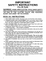
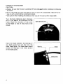
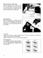
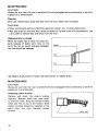
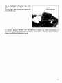
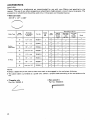
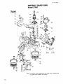
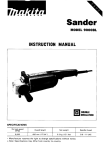
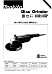
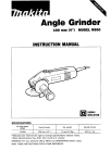
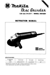
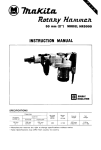
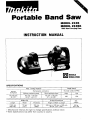
Portable Band Saw
MODEL 2106
MODEL 2106K
Wlth Steel Carrylnlpcase
INSTRUCTION MANUAL
SPECIFICATIONS
-~
~
~
Blade speed
Max. cutting capacity
Round
workpiece
Without optional stand
With optional stand
High
Low
115 mm dia.
14-112")
115 mm x 115 mm
14-1/2"x 4-112")
75 mm x 110 mm
(3"x 4-3/8")
260
200
Overall dimensions
Blade size
Length
1,140mm
144-718"')
~
+
No load surface (FPM)
Rectangular workpiece
Width
Thickness
13 mm
1112")
0.5 mm
LO207
~~~~~
Height x Width x Length
Net
weight
235 mm x 230 mm x 500 mm
(9-114'x 9" x 20')
5.5kg
(12.1lbs)
~~
Manufacturer reserves t h e r i g h t t o change specifications without notice
Note: Specifications m a y differ f r o m c o u n t r y t o country.
IMPORTANT
SAFETY INSTRUCTIONS
(For All Tools)
WARNING: WHEN USING ELECTRIC TOOLS, BASIC SAFETY
PRECAUTIONS SHOULD ALWAYS BE FOLLOWED TO REDUCE
THE RISK OF FIRE, ELECTRIC SHOCK, AND PERSONAL
INJURY, INCLUDING THE FOLLOWING:
READ ALL INSTRUCTIONS.
1. KEEP WORK AREA CLEAN. Cluttered areas and benches invite injuries.
2. CONSIDER WORK AREA ENVIRONMENT. Don't use power tools in damp
or wet locations. Keep work area well lit. Don't expose power tools t o rain.
Don't use tool in presence of flammable liquids or gases.
3. KEEP CHILDREN AWAY. All visitors should be kept away from work area.
Don't let visitors contact tool or extension cord.
4. STORE IDLE TOOLS. When not in use, tools should be stored in dry, and high
or locked-up place - out of reach of children.
5. DON'T FORCE TOOL. It will do the job better and safer at the rate for which
it was intended.
6. USE RIGHT TOOL. Don't force small tool or attachment t o do the job of a
heavy-duty tool. Don't use tool for purpose not intended; for example, don't
use circular saw for cutting tree limbs or logs.
7. DRESS PROPERLY. Don't wear loose clothing or jewelry. They can be caught
in moving parts. Rubber gloves and non-skid footwear are recommended
when working outdoors. Wear protective hair covering t o contain long hair.
8. USE SAFETY GLASSES. Also use face or dust mask i f cutting operation is
dusty.
9. DON'T ABUSE CORD. Never carry tool by cord or yank it t o disconnect from
receptacle. Keep cord from heat, oil, and sharp edges.
10. SECURE WORK. Use clamps or a vise t o hold work. It's safer than using
your hand and it frees both hands t o operate tool.
11. DON'T OVERREACH. Keep proper footing and balance at all times.
12. MAINTAIN TOOLS WITH CARE. Keep tools sharp and clean for better and
safer performance. Follow instructions for lubricating and changing accessories. Inspect tool cords periodically and if damaged, have repaired by authorized service facility. Inspect extension cords periodically and replace if
damaged. Keep handles dry, clean, and free from oil and grease.
13. DISCONNECT TOOLS. When not in use, before servicing, and when changing accessories, such as blades, bits, cutters.
2
14. REMOVE ADJUSTING KEYS AND WRENCHES. Form habit of checking t o
see that keys and adjusting wrenches are removed from tool before turning
it on.
15. AVOID UNINTENTIONAL STARTING. Don‘t carry tool with finger on switch.
Be sure switch is OFF when plugging in.
16. EXTENSION CORDS. Make sure your extension cord is in good condition.
When using an extension cord, be sure t o use one heavy enough t o carry
the current your product will draw. A n undersized cord will cause a drop
in line voltage resulting in loss of power and overheating. Table 1 shows the
correct size t o use depending on cord length and nameplate ampere rating.
If in doubt, use the next heavier gage. The smaller the gage number, the
heavier the cord.
TABLE 1
I
I
MINIMUM GAGE FOR CORD SETS
Total Length of Cord in Feet
0
~
25
I
26
~
Ampere Rating
More
Not More
Than
Than
0
6
10
12
~
~
6
10
12
16
50
1
51
100
~
I
101
~
150
A W G
18
18
16
14
16
16
16
12
;:
14
1
14
12
12
Not Recommended
17. OUTDOOR USE EXTENSION CORDS. When tool is used outdoors, use only
extension cords intended for use outdoors and so marked.
18. STAY ALERT. Watch what you are doing, use common sense. Don’t operate
tool when you are tired.
19. CHECK DAMAGED PARTS. Before further use of the tool, a guard or other
part that is damaged should be carefully checked t o determine that it will
operate properly and perform its intended function. Check for alignment of
moving parts, binding of moving parts, breakage of parts, mounting, and any
other conditions that may affect its operation. A guard or other part that
is damaged should be properly repaired or replaced by an authorized service center unless otherwise indicated elsewhere in this instruction manual.
Have defective switches replaced by authorized service center. Don’t use
tool if switch does not turn it on and off.
20. GUARD AGAINST ELECTRIC SHOCK. Prevent body contact with grounded
surfaces. For example; pipes, radiators, ranges, refrigerator enclosures.
21 . REPLACEMENT PARTS. When servicing, use only identical replacement parts.
22. POLARIZED PLUGS. To reduce the risk of electric shock, this equipment has
a polarized plug (one blade is wider than the other). This plug will fit in a
polarized outlet only one way. If the plug does not fit fully in the outlet,
reverse the plug. If it still does not fit, contact a qualified electrician t o install
the proper outlet. Do not change the plug in any way.
3
VOLTAGE WARNING: Before connecting the tool t o a power source (receptacle,
outlet, etc.) be sure the voltage supplied is the same as that specified on the
nameplate of the tool. A power source with voltage greater than that specified
for the tool can result in SERIOUS INJURY t o the user - as well as damage t o
the tool. If in doubt, DO NOT PLUG IN THE TOOL. Using a power source w i t h
voltage less than the nameplate rating is harmful t o the motor.
ADDITIONAL SAFETY RULES
I.e;,
1
and
only blades which are
1,140m m (44-7/8")
long; 13 m m (1/2")
wide;
0.5 m m (.020") thick.
2. Check the blade carefully for cracks or damage before operation. Replace
cracked or damaged blade immediately.
3. Secure the workpiece firmly. When cutting a bundle of workpieces, be sure
that all workpieces are secured together firmly before cutting.
4.Cutting workpieces covered with oil can cause the blade t o come off
unexpectedly. Wipe off all excess oil from workpieces before cutting.
5. Never use cutting oil as a cutting lubricant. Use only Makita cutting wax.
6. Do not wear gloves during operation.
7. Hold the tool firmly with both hands.
8. When cutting metals, be cautious of hot flying chips.
9. Do not leave the tool running unattended.
IO. Do not touch the blade or the workpiece immediately after operation; they
may be extremely hot and could burn your skin.
SAVE THESE INSTRUCTIONS.
4
Switch action
To start the tool, simply pull the trigger.
Release the trigger to stop. For continuous
operation, pull the trigger and then push in
the lock button. To stop the tool from the
locked position, pull the trigger fully, then
release it.
I
1
Lock button
1
Trigger switch
1
CAUTION :
Before plugging in the tool, always check to see that the trigger switch actuates properly
and returns to the "OFF" position when released.
Speed change
To change the tool speed, press the "H"
side of the speed change switch for high
speed or the "L" side for low speed.
CAUTION :
Do not change the tool speed while the motor is running.
5
Installing or removing blade
CAUTION :
Always be sure that the tool is switched off and unplugged before installing or removing
the blade.
Oil on the blade can cause the blade to slip or come off unexpectedly. Wipe off all excess oil with a cloth before installing the blade.
0 Use caution when handling the blades so that you are not cut by their sharp teeth
Turn the blade tightening lever clockwise
until it hits against the protrusion on the
frame. Match the direction of the arrow
on the blade to that of the arrow on the
wheels.
Insert the blade between the bearings of
one blade guide first and then into the
other blade guide. The blade back should
contact the bearings in the lower portion
of the blade guides.
Blade tightening lever
v
Bearing
,,
r\-\
6
Blade
Blade guide
I
Position the blade around the wheels and
insert the other side of the blade within the
Blade guide
IT---
Hold the blade in place and turn the blade tightening lever counterclockwise until it hits
against the protrusion on the frame. This places proper tension on the blade. Make sure
that the blade is correctly positioned within the blade guard and around the wheels.
Start and stop the tool two or three times to make sure that the blade runs properly on
the wheels.
CAUTION :
While making sure that the blade runs on the wheels properly, keep your body away from
the blade area.
To remove the blade, follow the installation procedures in reverse.
CAUTION :
When turning the blade tightening lever clockwise to release the tension on the blade, the
blade may come off unexpectedly. Be careful.
Installing stopper plate (For Model 2106 only)
This tool i s shipped from the factory without the stopper plate installed. Install the
stopper plate as follows.
Install the stopper plate on the frame so
that the blade can run through the slot in
the stopper plate. While pressingthe stopper
plate against the frame, secure the stopper
plate with the bolts using the hex wrench.
7
Squaring blade with stopper plate
Use the triangular rule to make sure that
the side of the blade i s square with the side
of the stopper plate. If not square, loosen
the bolts securing the stopper plate and
adjust the stopper plate accordingly.
Triangular rule
Cutting lubricant
When cutting metals, use Makita cutting
wax as a cutting lubricant. To apply the
cutting wax to the blade teeth, start the
tool and cut in to the cutting wax as shown
in the figure.
CAUTION :
Never use cutting oil or apply excessive amount of wax to the blade. I t may cause the
blade to slip or come off unexpectedly.
0 When cutting cast iron, do not use any cutting lubricant.
0
Cutting operation
It i s important to keep a t least two teeth in
the cut. Select the proper cutting position
for your workpiece by refering to the
figure a t right.
8
, o ,x
,
Hold the tool as shown in the figure with
the stopper plate contacting the workpiece
and the blade clear of the workpiece.
Turn the tool on and wait until the blade attains full speed. Gently lower the blade into
the cut. The weight of the tool or slightly pressing the tool down will supply adequate
pressure for the cutting. Do not force the tool.
As you reach the end of a cut, release pressure and, without actually raising the tool, lift
it slightly so that it will not fall against the workpiece.
CAUTION :
Applying excessive pressure to the tool or twisting of the blade may cause bevel cutting
or damage to the blade.
0 When not using the tool for a long period of time, remove the blade from the tool.
0
9
MA1NTENANCE
CAUTION :
Always be sure that the tool i s switched off and unplugged before attempting to perform
inspection or maintenance.
Cleaning
After use, remove wax, chips and dust from the tool, wheel tires and blade.
CAUTION :
Never use solvents such as turpentine, gasoline, lacquer, etc. to clean plastic parts.
0 Wax and chips on the tires may cause the blade to slip and come off unexpectedly. Use
a dry cloth to remove wax and chips from the tires.
0
Replacing tires on wheels
When the blade slips or does not track properly because of badly worn tires, or the
lip of the tire on motor side gets damaged,
the tires should be replaced.
Wheel
I
Ask Makita Authorized or Factory Service Centers to replace them.
MA1NTENANCE
CAUTION :
Always be sure that the tool is switched off and unplugged before attempting to perform
inspection or maintenance.
Replacing carbon brushes
Remove and check the carbon brushes
regularly. Replace when they wear down
to the limit mark. Keep the carbon brushes
clean and free to slip in the holders. Both
carbon brushes should be replaced at the
same time. Use only identical carbon
brushes.
10
'I
L
Limit mark
Use a screwdriver to remove the brush
holder caps. Take out the worn carbon
brushes, insert the new ones and secure the
brush holder caps.
I
Brush holder cap
To maintain product SAFETY and RELIABILITY, repairs, any other maintenance or
adjustment should be performed by Makita Authorized or Factory Service Centers,
always using Makita replacement parts.
11
ACCESSORIES
CAUTION :
These accessories or attachments are recommended for use with your Makita tool specified in this
manual. The use of any other accessories or attachments might present a risk of injury to persons. The
accessories or attachments should be used only in the proper and intended manner.
0
Band saw blade
44-718" x 112" x .020'
Workpiece t o be cut
Thickness
of workpiece
Blade Type
Part NO.
t o be c u t
10
1/2"+over
792567-A
14
1/4"-
792560-A
24
10
14
1/2"
Lersthan 1 / 8 '
112"+over
1/4" - 1 / 2 "
792558.A
792557-8
792557-A
py;,
Tool
Blades
,
H
3
H
,
3
3
-
1
1
24
1/8"-
1/4'
L e s r t h a n 118"
792556-A
1
792555-A
1
M i l d steel,
East
Hard steel
ferrous
metal
and
cast iron
r t i k s
steel
Wood
0
0
0
I
0
I
I
l
n
0
H
,
0
H
0
o
I
I
1
0
L
8i-Metal
18
Plastics
and
H
0
H
0
L
0
0
0
0
0
0
0
0
NOTE :
a blade which will allow a t least two teeth to be engaged in the workpiece thickness.
0The above table is provided as a guide only. Select a proper blade according to the workpiece to be
cut.
0 Select
0
Triangular rule
Part No. 762001-3
12
0
Hex wrench 4
Part No. 783209-6
Cutting wax
Part No. 191897-9
Portable band saw stand
Part No. 122370-8
( F o r accurate square cutting operations)
Steel carrying case
Part No. 823204-5
13
Feb.-04-'88
EN
PORTABLE BAND SAW
Model 2106
Note: The switch, noise suppressor and other part configurations
may differ from country to country.
14
MODEL 2106
E
'M
Feb.-04-'BB
DESCRIPTION
1
2
2
1
6
1
6
4
7
8
9
10
11
1
1
1
1
1
14
15
16
17
18
19
20
21
22
23
24
25
26
27
28
29
30
31
32
33
34
35
36
37
38
39
40
41
42
43
44
1
2
1
1
1
1
1
1
1
1
1
1
1
1
1
3
3
1
1
1
1
1
1
1
1
1
1
1
1
1
1
1
1
1
1
1
:: I
45
46
47
48
49
I
;
DESCRIPTION
MACHlNE
MACHINE
1
2
3
4
5
'LtM ,&
US
Hex Socket Head Bolt M6x4O IWith Washer1
50
Flat Washer 6
Grip 80
Hex Socket Head Bolt M5x22
Frame Cover
Hex Socket Head Bolt M5x10
Laver 60
Flat Washer 20
Upper Holder
Ball Bearing 69622
Flat Washer 6
Ball Bearing 69622
Spnng Washer 6
Pan Head Screw M 5
Pan Head Screw M5xZB lWnh Washer1
Ball Bearing 69622
Pin 6
Ball Bearing 69622
Flat Washer 6
Ball Bearing 69622
Spring Washer 6
Pan Head Screw M 5
Campresslo" Spring 11
Tension Plate
Compression Spring 11
Sleeve 5
Pan Head Screw M5x16 With Washer)
51
52
53
54
55
56
Slide Plate
Sleeve 5
Pan Head Screw M5x25 (With Washerl
Flat Washer 16
Rubber Tire
Wheel
Flat Washer 16
Hex Socket Head B O I ~~ 6 x21
Ball Bearing 69622
Pin 6
Ball Bearing 69622
Flat Washer 6
Pan Head Screw M 5
Spring Washer 6
Ball Bearing 69622
Pan Head Screw M 5
Spring Washer 6
Ball Bearing 69622
Flat Washer 6
Ball Bearing 69622
Lower Holder
Pan Head Screw M5x28 IWith Washer)
57
58
59
60
61
62
63
6 4
65
66
67
68
69
70
71
72
73
74
75
76
77
78
79
BO
81
82
83
84
85
86
87
a8
89
90
91
93
94
95
96
97
98
1
1
1
1
1
1
1
1
2
1
1
1
1
1
1
1
1
1
1
1
1
1
1
1
1
1
1
1
1
1
4
4
2
2
1
1
2
1
5
1
1
1
1
1
2
1
1
1
Hex. Socket Head Bolt M6x12
Flat Washer 16
Wheel
Rubber Tire
Flat Washer 16
Frame
Name Plate
Stopper Plate
Hex. Socket Head Bolt M5x25
Rubber Pin 4
Ball Bearing 608
Gear 11-45
Flat Washer 8
Needle Beanng 810
Key 4
Spur Gear 9
Rubber Pin 6
Ball Bearing 6201LB
Helical Gear 42
Sleeve 12
Ball Bearing 6000
Cap 26
Rubber Pin 4
Gear Housing
Ball Bearing 629LB
Rubber Pm 4
Fan 62
ARMATURE ASSEMBLY
IWnh Item 7 4 6 76 - 781
Ball Bearing 608LB
Rubber Pin 4
Hex. Socket Head Bolt M6r6O lWith Washer)
Flat Washer 6
Brush Holder Cap
Carbon Brush
Motor Housing
FIELD ASSEMBLY
Hex. Bolt M5x50 IWith Washer)
Baffle Plate
Pan Head Screw M5x28 IWnh Washer)
Handle Set IWith Item 911
Switch
Handbe Set IWith Item 891
Switch
Switch Protector
Pan Head Screw M4r18 (With Washer)
Strain Relief
Cord Guard
Cord
Note. The Switch and other part specifications may differ from country 10 country.
15
r
MAKCTA LIMITED ONE YEAR WARRANTY
Warranty Policy
Every Makita tool is thoroughly inspected and tested before leaving the factory. It is warranted t o
be free of defects from workmanship and materials for the period of ONE YEAR from the date of
original purchase. Should any trouble develop during this one-year period, retum the COMPLETE
tool, freight prepaid, to one of Makita’s Factory or Authorized Service Centers. If inspection shows
the trouble is caused by defective workmanship or material, Makita will repair (or at our option,
replace) without charge.
This Warranty does not apply where:
repairs have been made or attempted by others:
0 repairs are required because of normal wear and tear:
The tool has been abused, misused or improperly maintained;
alterations have been made to the tool.
IN NO EVENT SHALL MAKITA BE LIABLE FOR ANY INDIRECT, INCIDENTAL OR CONSEQUENTIAL DAMAGES FROM THE SALE OR USE OF THE PRODUCT. THIS DISCLAIMER
APPLIES BOTH DURING AND AFTER THE TERM OF THIS WARRANTY.
MAKITA DISCLAIMS LIABILITY FOR ANY IMPLIED WARRANTIES, INCLUDING IMPLIED
WARRANTIES OF “MERCHANTABILITY” AND “FITNESS FOR A SPECIFIC PURPOSE.”
AFTER THEONE-YEARTERM OF THIS WARRANTY.
This Warranty gives you specific legal rights, and you may also have other rights which vary from
state to state. Some states do not allow the exclusion or limitation of incidental or consequential
damages, so the above limitation or exclusion may not apply to you. Some states do not allow
limitation on how long an implied warranty lasts, so the above limitation may not apply to you.
Makita Corporation
3-11-8, Sumiyoshi-cho,
Anjo, Aichi 446 Japan
8836540068
PRINTED IN JAPAN
1995
-4 -N