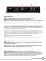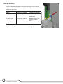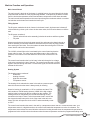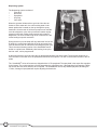
1
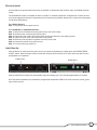
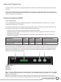
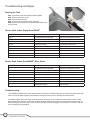
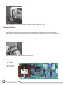
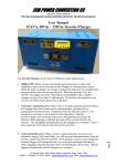
BUNN® TECHNICAL TRAINING
Smar tWAVE®
Index
Unit 1: Installation
Site Requirements............................................................................................................... 4
Location of the Serial Number........................................................................................... 4
Water Supply Install............................................................................................................ 4
Electrical Install................................................................................................................... 5
Initial Start-Up...................................................................................................................... 5
Unit 2: Setup
Setup and Programing........................................................................................................ 7
Programming Digital SmartWAVE®............................................................................. 7
Programming SmartWAVE® Silver Series................................................................... 8
Program Switches............................................................................................................... 10
Unit 3: Machine Composition
Exterior Overview................................................................................................................ 12
Product Outlets and Removable Parts ...................................................................... 12
User Interface................................................................................................................ 12
Accessing the Inside of the Brewer................................................................................... 12
Machine Function and Operations..................................................................................... 13
Main Control Board....................................................................................................... 13
Filling System................................................................................................................ 13
Heating System............................................................................................................. 13
Dispensing System....................................................................................................... 14
Unit 4: Preventive Maintenance
Preventive Maintenance...................................................................................................... 16
PM Steps.............................................................................................................................. 16
Unit 5: Troubleshooting
Drain the Tank...................................................................................................................... 18
Service Fault Codes - Digital SmartWAVE®....................................................................... 18
Service Fault Codes - SmartWAVE® Silver Series............................................................ 18
Troubleshooting.................................................................................................................. 19
Filling System................................................................................................................ 19
Heating System............................................................................................................. 19
Brewing System............................................................................................................ 20
Rev. B
© 2009 Bunn-O-Matic Corporation. All Rights Reserved
Unit 1 Installation
Unit Objectives
Given a realistic scenario depicting a new site install, the learner will be able to install and setup the brewer
for retail turnover without error.
Given a new machine, all the necessary tools and safety equipment, the learner will be able to install
the brewer without error.
The learner will be able to verify that the site requirements have been met.
The learner will be able to locate and document the serial number.
The learner will be able to hook up the water supply.
The learner will be able to hook up the electrical supply.
Installation
Site Requirements
Space
•
•
•
•
Height clearance of 19”
Footprint able to accommodate 10” W x 18” D
Counter able to support 25lbs
Level installation surface, brewer level on the surface
Water Treatment
•
•
•
•
Sediment filtration to reduce large particles
Taste and odor filter to remove chlorine
Scale filtration as needed
For best results a BUNN® Easy Clear® filtration system should be used
Plumbing
•
•
•
•
.75-11.5 NH (3/4” hose thread) fitting (¼” flare adapter included)
Dedicated water supply with shut-off
Connected to the cold water supply
Water pressure 20-90 psi
Electrical (120VAC)
•
•
•
•
•
120VAC
2-wire plus ground (L1, neutral, ground)
15 amp dedicated circuit (breaker, plug, and receptacle)
Receptacle within 5 feet of the machine
Power cord and plug included
Electrical (208VAC or 240VAC)
•
•
•
•
120/208VAC or 120/240VAC
3-wire plus ground (L1, L2, neutral, ground)
15 amp dedicated circuit (breaker, plug, and receptacle)
Receptacle within 5 feet of the machine
Location of the Serial Number
The machine’s serial number is located on the data plate which is
adhered to the rear panel below the control board access panel. The
complete serial number will need to be documented on all work orders
and warranty tags.
Water Supply Install
Step 1: Remove the shipping cap from the fitting on the rear of the brewer
Step 2: Install the .75-11.5 NH to ¼” flare adapter on the rear of the brewer;
be sure to use the included rubber washer.
Step 3: Flush the water line.
Step 4: Attach the water line to the ¼” flare fitting on the back of the machine.
Step 5: Turn on the water supply
4
SmartWAVE® Training Manual
Electrical Install
An electrician must provide electrical service as specified in conformance with all local, state, and federal electrical
codes.
The SmartWAVE® brewer is available as either a 120VAC or 120/208-120/240VAC configured unit. Ensure the location has the appropriate electrical requirements for the brewer being installed. Always refer to the brewer’s data plate
for electrical specifications.
For 120VAC Brewers:
Step 1: Plug brewer into the power source.
For 120/208VAC or 120/240VAC Brewers:
Step 1: Remove the terminal block access panel on the rear of the brewer.
Step 2: Feed the power cord through the strain relief.
Step 3: Connect the wire ends to the terminal block and the ground wire to the chassis ground.
Step 4: Tighten the strain relief and reinstall the access panel.
Step 5: Install the cord cap onto the opposite end of the power cord.
Step 6: Connect the brewer to the power source.
Step 7: Turn the main power switch on.
Initial Start-Up
After the brewer is connected to the power source or turned on (depending on model) press the ENABLE BREW
ON/OFF switch. Water will begin to flow into the tank and stop when the tank is full. Some water may drip from the
sprayhead due to expansion.
Enable Brew
TM
Enable Brew
TM
After the tank fills the machine will automatically begin the heating cycle. This will take approximately 20 minutes.
Once the water temperature has reached the programmed temperature READY will scroll across the screen (green
light on Silver series).
5
Bunn-O-Matic Corporation
Unit 2 Setup
Unit Objectives
Given a realistic scenario depicting a new site install, the learner will be able to install and setup the brewer
for retail turnover without error.
Given an installed machine, all the necessary tools and safety equipment, the learner will be able to
set the machine up for initial operation.
The learner will be able to power on the machine.
The learner will be able to access and scroll through the programming options.
The learner will be able to perform the calibrations.
Setup and Programming
Accessing and using the brewer’s programming features is done from the user interface panel and requires no special tools.
Water volumes and flow settings for the SmartWAVE® brewer have been preset at the factory. The volumes can be
increased or decreased and optional pulse brewing can be programmed. Additionally there are four programming dip
switches located on the control board.
Programming Digital SmartWAVE®
Level 1 Programming
Level 1 programming contains the programming options for the product parameters. Access to level 1 is done by
pressing the hidden switch for 5 seconds.
The two brew buttons allow for two different recipes and/or batch sizes to be stored on the brewer. Each button has
three different settings than can be tuned to specific customer requirements:
•
•
•
Brew Time: the time required in order to achieve the desired brew volume.
Pulse Brew setting: the number of desired “pulses.” During a “pulse” the machine cycles the brew function off,
allowing the funnel to drain.
Drip Out time: the time after the brew that the funnel is draining into the server before the funnel should be re
moved from the machine.
Brew Button A*
Default
Minimum
Maximum
Adjustment Increments
A1: Batch Size (time)
2:05
0:26
5:00
Seconds
A2: BrewMeter(pulse brew cycles)
1
1
14
1-14
0:05
5:00
5 second
A3: Drip out (time)
1:00
* Values are the same for Brew Button B
When programming the SmartWAVE® brewer It is important to know what type of holding vessel the customer will be
using in order to set batch sizes. The brewer can accept a variety of airpots and carafes. Even though the brewer’s
clearance can accomodate a 3.0 L airpot, the largest vessel recommended for use with the SmartWAVE® is a 2.5 L
airpot due to the size of the machine’s tank.
1
2
3
4
TM
1 Hidden switch
2 Display
3 Brew A ( - )
4 Brew B (+)
Step 1: Press the hidden switch until the display reads A1. This represents the adjust mode Brew Time for the A brew
switch. The display will toggle between A1 and the setting. Press the BREW A button to decrease time or the BREW
B button to increase time.
Step 2: Press the hidden switch until the display reads A2. This represents the adjust mode Brew Meter (Pulse
Brew) for the A brew switch. The display will toggle between A2 and the setting. The brewer has 14 preset pulse brew
7
Bunn-O-Matic Corporation
routines to choose from. Factory default is 1; with 14 being the maximum. Press BREW A to decrease or BREW B to
increase.
Step 3: Press and release the hidden switch until display reads A3. This represents the adjust mode Drip-Out Time
for the A brew switch. The display will toggle between A3 and the setting. Press the BREW A button to decrease time
or the BREW B button to increase time.
Step 4: Repeat steps 1 -3 for setting the “B” brew switch.
Level 2 Programming
Level 2 programming contains some of the machine parameters. Additional parameters are set on the control board
using dip switches. Access to level 2 is done by pressing the hidden switch for 10 seconds.
Option
Default
Minimum
Maximum
Adjustment Increments
P1: Temperature set point
200º F
185º F
205º F
1 Degree
P2: Ready Temperature
195º F
180º F
198º F
1 Degree
P3: Display Brew Count
0
0
9999
N/A
P4: Fahrenheit or Celsius
F
N/A
Level 3 Programming
Level 3 programming contains 8 menus which include calibration and factory set-up menus for the sequence steps
used throughout a WAVE brew cycle. Access to level 3 is done by pressing the hidden switch for 15 seconds.
U1: This screen can not be adjusted however, it displays the current water condition number when the water
is touching the probe. Range: 0/open refill probe – 232/shorted refill probe.
U2: Calibration of water refill threshold. Default: 85, Adjustment Range: 30 – 220
This screen is used to set the sensitivity of the refill circuit which, can be adjusted for different water condi
tions. Increase default number according to very soft water. The relative water condition number can be
viewed in U1 menu when water is touching the refill probe.
U3 to U7: Factory Setup Menus.
Warning: Do Not Adjust!
U8: Calibration menu for the temperature sensor.
This screen is used to calibrate the thermistor reading and CBA to the actual temperature.
Restore Factory Defaults
Step 1: Unplug the brewer.
Step 2: Press the ENABLE BREW ON/OFF switch and plug the brewer into the power source.
Step 3: Press the ENABLE BREW ON/OFF switch for 10 seconds. During those 10 seconds the middle bars on the
display will be on. After 10 Seconds the 3 upper, middle and lower bars on the display will be lit for 5 seconds. During those 5 seconds, release and again press the ENABLE BREW ON/OFF switch to restore default settings – the
display will read DONE.
To exit the programming mode at any time, press and release the ON/OFF button located on the user interface. The
display will return to the main screen.
If the programming cannot be access then the programming lockout dip switch is in the ON position. The switch is
located on the control board. Remove the control board access panel, locate the switch and place it into the OFF
position.
Programming SmartWAVE® Silver Series
The Silver Series brewer can brew two different batch sizes. Note that the maximum water on time is 5 minutes.
When programming the SmartWAVE® brewer It is important to know what type of holding vessel the customer will be
using in order to set batch sizes. The brewer can accept a variety of airpots and carafes.
8
SmartWAVE® Training Manual
1
4
2
3
TM
1 Enable Brew On/Off Switch
2 Small Brew Switch
3 Large Brew Switch
4 Status Indicator (LED)
Step 1: Place an empty funnel in the funnel rails and an empty server beneath the funnel.
Step 2: Press the ENABLE BREW ON/OFF switch placing it in the ON position.
Step 3: Press and hold the small brew start switch until the LED indicator alternately flashes red/green (approximately 15 seconds). Release the switch.
Step 4: Allow the cycle to continue until the desired amount of water is dispensed and then press the ENABLE
BREW ON/OFF to turn OFF the brewer.
The brewer is now set to dispense this amount of water for each small brew cycle. To increase the amount of water,
place an empty funnel in the funnel rails and an empty server beneath the funnel. Press the ENABLE BREW ON/
OFF switch ON. Press and hold the small BREW switch until you hear the solenoid click three times (approximately
10 seconds), then release the switch. Momentarily press and release the small BREW switch once for each ounce of
water to be added to the setting and allow the brew cycle to finish.
To decrease the amount of water for each brew cycle, place an empty funnel in the funnel rails and an empty server
beneath the funnel. Press the ON/OFF” switch ON. Momentarily press and release the small BREW switch once for
each ounce of water to be removed from the setting. Press and hold the small BREW switch until you hear the solenoid click three times (approximately 10 seconds), then release the switch and allow the cycle to finish.
Note: Repeat the steps above to set the large batch by using the large brew switch.
Optional Pulse Brew Setup
Note: Set small and large batches separately. Brewer has 4 preset pulse brew routines to choose from. Factory default is 1 with 4 being the maximum time.
Step 1: With the machine off, press the small or large switch for 10 seconds. Red LED will flash to indicate current
setting (1 – 4).
Step 2: Press the same switch the number of times (1 – 4) for the desired setting. After 5 seconds the red LED will
resume flashing the selected number.
When no switches are pressed for 30 seconds, the mode will exit. Or the mode may be exited by pressing the ENABLE BREW ON/OFF switch. Repeat above procedure with the other brew switch.
Note: No other additional settings are available on the Silver Series.
Restore Factory Defaults
Step 1: Unplug the brewer.
Step 2: Press the ENABLE BREW ON/OFF in the On position and plug the brewer into the power source.
Step 3: Press the ENABLE BREW ON/OFF switch for 10 seconds. During those 10 seconds, the red LED will be on
steady. After 10 seconds the green LED will begin flashing rapidly for 5 seconds. During those 5 seconds, release
and again momentarily press the ENABLE BREW ON/OFF switch again to restore default settings. The LED will
alternate rapidly Red and Green for a few seconds indicating the restore has been accomplished.
9
Bunn-O-Matic Corporation
Program Switches
There are 4 dip switches located on the control board that control optional
settings on the SmartWAVE® brewer. All of these switches are set to the OFF
position from the factory.
Function- Off position
1 Program Lockout
Programming allowed
Programming locked out
2 Brew Lockout
Brew at any temperature
Only brews at Ready
temperature
3 Energy Save
Energy save mode off
Maintains 140° F after
6 hours, Off after 26
hours
4 High Altitude
Set tank temp. 200° F
10
SmartWAVE® Training Manual
ON
Function- On position
Set tank temp at 190° F
1234
Switch #
OFF
Unit 3 Machine Composition
Unit Objectives
Given a realistic scenario in which the learner has access to the machine’s internal components the learner
will understand the composition and functions of the brewer.
Given a realistic scenario requiring the learner to access the internal components of the machine the
learner will be able to remove the shroud, top panel, and control board access panel.
The learner will remove the shroud, top panel, and control board access panel.
Given an operating machine the learner will be able to give a general explanation of how the unit
operates.
The learner will be able to identify the functions of the main control board .
The learner will be able to identify the components and functions of the filling system.
The learner will be able to identify the components and functions of the heating system.
The learner will be able to identify the components and functions of the dispensing system.
Machine Composition
2
Exterior Overview
Product Outlets and Removable Parts
•
•
•
•
•
1
3
User interface (1)
Hot water outlet (2)
Sprayhead (3)
Adjustable server base (4)
Adjustable legs (5)
User Interface
4
5
The SmartWAVE brewer control panel features membrane switches and an alphanumeric display.
D
E
A
B
C
®
TM
A.
B.
C.
D.
E.
Enable Brew On/Off switch
Brew A switch
Brew B switch
Hidden programming switch
Display
The SmartWAVE® Silver series control panel features mechanical switches and LED status lights.
A
D
B
C
TM
A.
B.
C.
D.
Enable Brew On/Off switch
Small batch switch
Large batch switch
Status indicator
Steady green- ready to brew
Steady red- tank heating
Flashing red- brewing
Accessing the Inside of the Brewer
The majority of service work to the SmartWAVE® brewer will require
the removal of the top panel, the front shroud or the control board
access panel on the rear. The top panel is secured with 2 philips
head screws. The rear panel is secured with 6 flathead screws, and
the rear panel is secured with four flathead screws.
12
SmartWAVE® Training Manual
Machine Function and Operations
Main Control Board
The main control is the brain of the brewer. In a digital brewer, the control board is the single
component that contains all of the programming software, it interprets all the data it receives
from the level and temperature sensors and activates components to fulfill those demands. The main control board responds to the users input through the membrane switch or mechanical switches and activates and controls the brew cycle.
Filling System
The fill system maintains the level of water in the brewer’s tank. Anytime water is drawn off
of the tank during a brew cycle or from the hot water outlet, the fill circuit activates to refill the
tank.
The fill system consists of:
•
120VAC solenoid inlet valve assembly (includes the strainer and flow regulator
•
Fill probe
Water enters the brewer through the water supply line and enters the chassis through a
strainer assembly; this strainer contains a fine mesh screen to keep any large particles
from entering the inlet valve. From the strainer the water flows through the 0.222 flow
control device and into the inlet solenoid.
The 120VAC solenoid inlet valve is activated by the control board anytime the
brewer calls for water. The valve opens and allows water to flow, under line
pressure, to the bottom of the tank where the silicon tube connects to the fill
tube.
The control board monitors the level of water in the tank through a low voltage
level probe mounted to the top of the tank. The control board grounds a 2.5VAC
signal to the tank through the water. If it looses this signal, the control board will
activate the inlet valve.
Heating System
The heating system consists of:
•
Water tank
•
Heating elements
•
High-limit thermostat
•
Temperature sensor
The heating circuit maintains the water in the tank at a preset temperature this ensures that the water is always ready for brewing.
Water for brewing is contained in a 155 oz. stainless steel tank. This
tank contains a 1320W heating element (1850W in the high voltage
machine) that is powered by the line voltage into the machine. The
heating element is controlled by the control board through a relay
mounted on the board. There is a limit thermostat wired in series with
the element that will interrupt the circuit if the water in the tank overheats. This limit will open the circuit at 230°F and automatically resets
at 170°F.
The control board monitors the water in the tank by a temperature sensor that is in contact with the water. This
temperature sensor is a digital thermistor; the control board reads the temperature as value of resistance. The
temperature sensor allows the control board to activate the heating element when the temperature drops below its
programmed value and shut down the element when the water temperature reaches the programmed holding value.
13
Bunn-O-Matic Corporation
Dispensing System
The dispensing system consists of:
•
Inlet valve
•
Brew tube
•
Sprayhead
•
Air pump
•
Vent valve
When the operator initiates a brew cycle the inlet valve activates to fill the water tank, the cold incoming water in the
bottom pushes the hot water on the top through the sprayhead tube. Once the tank is full the air pump turns on and the
vent valve begins to cycle, this cycle actions creates varying
pressure in the tank creating a wave action as the water is
dispensed. The wave creates a high level of turbulence in the
coffee leading to superior extraction.
During the brew cycle the water will drop below the level of the
fill probe, the control board will shut off the air pump and vent
valve to allow the tank to refill before continuing the brew cycle.
This is the normal brewing routine of the SmartWAVE and is
similiar to a pulse brew. Additional pulse brewing, that cycles
the inlet valve, can be programmed.
At the end of the brew cycle the inlet valve is deenergized and the vent valve closes. The air pump remains on to
force the water in the tank out of the sprayhead tube below the fill probe. The refill circuit then fills the tank to the fill
probe.
The SmartWAVE® series of brewers are shipped with a 6-078 sprayhead. The sprayhead is the output flow regulator
for the brewer. The number and size of holes determines the output flow rate. If the sprayhead is changed to a different number the brew times will have to be adjusted. The SmartWAVE can use any BUNN sprayhead, including the
17 hole, A change of sprayhead will require adjusting the batch size.
14
SmartWAVE® Training Manual
Unit 4 Preventive Maintenance
Unit Objectives
Given a realistic scenario depicting a machine requiring a preventive maintenance, the learner will be able to
identify which elements of a component need to be serviced without error.
Given a machine, all the necessary tools and safety equipment, the learner will be able to identify the
components that need to be serviced for the PM.
Preventive Maintenance
In order to maintain proper operation and long service life BUNN® recommends performing the preventative maintenance every 6 months. Individual customers will vary with some customers choosing not to receive preventative
maintenance.
Tools Required:
• Flat blade screwdriver
• Philips screwdriver
• Adjustable wrench
• Channel lock pliers
• Needle nose pliers
• Deliming spring (BUNN P/N: 01188.0000)
• Deliming tool (BUNN P/N: 38227.0000)
Prior to servicing the brewer:
• Disconnect the electrical supply
• Shut off the water supply
• Remove the shroud
• Remove the top panel
PM Steps
Step 1: Disassemble and clean the strainer assembly
□□ Use Channel lock pliers to remove the ¼” flare to ¾” hose thread adapter fitting from the water inlet assembly
□□ Use needle nose pliers to gently pull the strainer straight out
□□ Rinse the mesh screen to remove any debris build-up
□□ Reassembly is the opposite of disassembly
Step 2: Remove and clean the temperature sensor
□□ Gently pull the temperature sensor from the grommet in the top of the tank
□□ Wipe any mineral build-up from the probe
□□ Reinstallation is the opposite of removal
Step 3: Remove and clean the fill probe
□□ Gently pull the fill probe out of the grommet
□□ Wipe any mineral deposits off of the probe
□□ Reinstallation is the opposite of removal
Step 4: Remove and clean the sprayhead
□□ Using the pointed end of the deliming tool, remove any mineral build-up from the sprayhead outlet holes
Step 5: Clean the sprayhead tube
□□ With the sprayhead removed Insert the deliming spring into the tube
□□ Using a sawing motion run the deliming spring through the tube several times and then remove the spring completely
Note: after cleaning the tube, the brewer should run one brew cycle with the sprayhead off in order to flush out the
tube.
Step 6: Replace the seat cup in the hot water faucet
□□ Unscrew the faucet bonnet from the assembly
□□ Remove the old faucet seat cup
□□ Install the new seat cup BUNN P/N: 02766.0000
□□ Reassembly is the opposite of disassembly
Step 7: Visually examine the power cord for any damage
Step 8: Visually examine the water supply for any leaks
16
SmartWAVE® Training Manual
Unit 5 Troubleshooting
Unit Objectives
Given a realistic scenario depicting a broken machine, the learner will be able to effectively troubleshoot,
diagnosis, and repair the problem returning the machine to normal operation.
Given a machine displaying an error message, all the necessary tools and safety equipment, the
learner will be able to diagnosis the problem.
Given a list of error messages and issues, the learner will be to identify the probable cause of the
message or issue.
Given a brewer with a defective component, the learner will be able to test the component to deter
mine the cause of the defect.
Troubleshooting and Repair
Draining the Tank
Step 1: Disconnect the water and electrical supplies.
Step 2: Remove the front cover.
Step 3: Pinch off the fill hose.
Step 4: Loosen the clamp from the fill solenoid.
Step 5: Remove the hose from the solenoid and drain into a
sink or bucket.
Service Fault Codes- Digital SmartWAVE®
Display Message
Description
Action
ER 1
Temperature sensor shorted
Check the temperature sensor
ER 2
Temperature sensor open
Check the temperature sensor
ER 3
Heating time too long
Troubleshoot heating circuit
ER 4
Refill time to long
Troubleshoot refill circuit
ER 5
High tank level- during brew
Delime sprayhead and tube
ER 6
Enable Brew On/Off switch
Check switch
ER 7
Brew A switch
Check switch
ER 8
Brew B switch
Check switch
ER 9
Hidden switch
Check switch
Service Fault Codes- SmartWAVE® Silver Series
Red LED Flashes
Description
Action
1
Temperature sensor shorted
Check the temperature sensor
2
Temperature sensor open
Check the temperature sensor
3
Heating time too long
Troubleshoot heating circuit
4
Refill time to long
Troubleshoot refill circuit
5
High tank level- during brew
Delime sprayhead and tube
6
Enable Brew On/Off switch
Check switch
7
Large batch switch
Check switch
8
Small batch switch
Check switch
Troubleshooting
Like all BUNN® equipment the most important tools required for troubleshooting are the wiring schematic and a multimeter. As with all digital equipment eliminate all component issues prior to replacing the control board.
It is always a good idea to do some quick checks prior to working on the machine to eliminate site issues. Check
water supply to the machine, make sure the water filtration output pressure is within specification and ensure all of
the water supply valves are open. Check to make sure the machine is plugged in, the breaker is turned on, and that
correct voltage is being supplied.
18
SmartWAVE® Training Manual
Filling System
Brewer Not Filling
Check the water supply to the brewer. Ensure that all valves are on, the water
filter is not clogged, and that the supply line is not restricted in anyway. Remove the supply line from the water inlet and open the water supply into a
bucket or sink to check water supply
With the water supply line removed, remove the adapter fitting and pull out the
strainer screen, check for build-up in the strainer screen and the flow control
device.
During the fill process, the inlet solenoid valve receives approximately 120VAC from the control board, check voltage
at the valve. Remove the wires from the valve and measure the resistance of the valve coil, it should read approximately 1400ohms.
Brewer Overfilling
Remove the fill probe and check for scale build-up on the fill probe. Clean or replace the probe.
Drain the tank and disconnect the electrical supply. If water is flowing into the
tank with the fill circuit deactivated water is leaking past the inlet solenoid and
the valve will need to be replaced.
Heating System
Brewer Not Heating
During the heating cycle the heating element will draw approximately 11amps. Use an amp clamp to check amperage on L1.
During the heating cycle the control board will supply approximately 120VAC
to the element. Place on of the multimeter’s probes onto the neutral side of
the heating element (the use of a clip-on style probe will simplify this process). Using the other end of the probe, check for voltage on the L1 side of
the element, both sides of the high-limit and on the control board at the connector marked Heater.
19
Bunn-O-Matic Corporation
Check for continuity through the high-limit thermostat.
Check the resistance of the heating element. It should read approximately 10-11 ohms.
Dispensing System
Not Brewing
During the brew process, the inlet solenoid valve receives approximately 120VAC from the control board, check
voltage at the valve. Remove the wires from the valve and measure the resistance of the valve coil, it should read approximately 1400ohms.
No Wave
Check the vent valve and air pump both components receive 12VDC from the control board.
Brew Basket Overflowing
Check the sprayhead tube and sprayhead for scale build-up.
Switching Component Map
1. TH1 = Heater
2. Q2 = Air Pump
3. Q4 = Vent Valve
4. Q8 = Inlet Valve
1
3
2
20
SmartWAVE® Training Manual
4