1
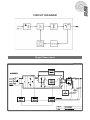
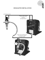
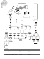
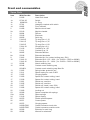
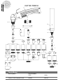
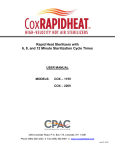
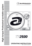
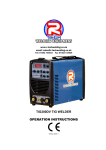
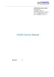
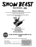
UNI FLAME AUTOLIFT
PLASMA CUT55/105
Inverter Air Plasma Manual
MILD STEEL
PLASMA CUT 55
MAXIMUM CUTTING CAPACITY 20MM
MILD STEEL
PLASMA CUT 105
MAXIMUM CUTTING CAPACITY 28MM
Plasma CUT
UNI FLAME AUTOLIFT
2YEARS Warranty
*
Machine Model
Description
Plasma Cut 55 - 105
Part Number
KUPJR55 - KUPJR105
CONTENTS
PAGE No:
Safety
3
General Description
4
Curcuit Diagram
5
Maim Parameters
6
Installation
7
Regulator Installation
9
Maintenace and Inspection
10
Machine Parts
11
Torch Consumables
12
Maintenance & Trobleshooting
16
Machine Model
EC DECLARATION OF CONFORMITY
Hereby we declare that our machines for industrial and professional
use as stated below:
Type: CUT55 / CUT105
Conform the EMC Directives: 73/23/EEC and 89/336/EEC
European Standard: EN/IEC60974
Please read and understand this instruction manual carefully
before the installation and operation of this equipment.
The contents of this manual may be revised without prior notice.
This instruction manual is issued on Nov. 20th 2007.
UNIMIG pursue a policy of continuous research and development, and therefore
reserve the right to change the specifications, or design, without prior notice. * 2 year warranty power source.
SAFETY
Welding and cutting equipment can be dangerous to both the operator and people in or near the
surrounding working area, if the equipment is not correctly operated. Equipment must only be
used under the strict and comprehensive observance of all relevant safety regulations. Please
read and understand this instruction manual carefully before the installation and use/operation
of this equipment.
not switch the function modes while the machine is operating.
• Do
Switching of the function modes during welding can damage the machine.
Damage caused in this manner will not be covered under warranty.
the electrode-holder cable from the machine before switching on the
• Disconnect
machine, to avoid arcing should the electrode be in contact with the work piece.
safety switch is necessary to prevent the equipment from electric leakage.
• AWelding
and accessories should be of high quality and in good working order.
• Operatorstools
be trained and or qualified. Electric shock: It can kill.
• Connect theshould
primary
cable according to Australian standard regulation.
• Avoid all contact withinput
live electrical parts of the welding circuit, electrodes and wires with
• bare hands. The operator
must wear dry welding gloves while he/she performs the
•
•
•
•
welding task.
The operator should keep the work piece insulated from
himself/herself. Smoke and gas generated whilst welding
or cutting can be harmful to people’s health.
Avoid breathing the smoke and gas generated whilst
welding or cutting. Keep the working area well ventilated.
Arc rays are harmful to people’s eyes and skin. Always
wear a welding helmet and suitable protective
clothing including welding gloves whilst the welding
operation is performed.
Measures should be taken to protect people in or near
the surrounding working area, from all hazards
associated with welding.
Fire hazard
welding sparks may cause fire, therfore remove
• The
flammable material away from the working area.
a fire extinguisher nearby, and have a trained
• Have
person ready to use it.
Noise: possibly harmful to people’s hearing.
Noise is generated while welding/cutting, wear approved
hearing protection when noise levels are high.
Machine fault:
Consult this instruction manual.
Contact your local dealer or supplier for further advice.
•
•
•
*** CAUTION ***
Do not heat, cut or weld tanks, drums or containers
until the proper steps have been taken to insure that
such procedures will not cause flammable or toxic
vapours from substance inside. These can cause
an explosion even though the vessel has been
“cleaned”.Vent hollow castings or containers before
heating, cutting or welding. They may explode.
UNI FLAME AUTOLIFT
GENERAL DESCRIPTION & SAFEGUARDS
The plasma cutting unit generates constant current and has been designed to cut
all electrically conductive materials including steel, cast Iron, stainless steel, copper,
aluminium brass etc .. The cutting process is carried out through the melting of the
metal caused by high temperature created by the electric arc between the torch
electrode and the base metal. The molten material is removed by a high-speed jet of
ionized gas (compressed air is the type of gas used).
This cutting machine is manufactured with advanced inverter technology. With
high-quality component MOSFET and PWM technology, the inverter converts DC
voltage, which is rectified from input AC voltage, to high 100KHz frequency AC voltage;
as a consequence, the voltage is transformed and rectified. This results in a small size
main transformer and light weight in the inverter plasma cutter.
EMC
Before installing the plasma cutting unit, carry out an inspection of the surrounding are,
observing the
following guidelines:
1
Make sure that there are no other power supply cables, control line, telephone
leads or other equipment near the unit.
2
Make sure that there are no radio receivers or television appliances.
3
Make sure there are no computers or other control systems.
4
Make sure that there is no-one with a pacemaker or hearing aid in the area
around the unit.
5
Check the immunity of any other equipment operating in the same environment
In certain cases additional protective measures may be required.
Interference can be reduced in the following ways:
(5a) If there is interference in the power supply line, an E.M.C filter should be inserted
between the main and the unit.
(5b) The output cables of the unit should be shortened; these should be kept close
together and stretched along the ground.
(5c) All the panels of the unit should be correctly closed after carrying out maintenance.
Our plasma cutting units are supplied with the following devices.
1
Thermal protection devices which are installed at the points most subject to high
temperatures such as the power transformers and the rectifying units. A yellow light on
the front panel lights up when the thermal protection device intervenes.
2
Electric shock protection device which prevents the operator from coming into
contact with the live parts of the torch (such as the electrode) This consists of a safety
device built into the body of the torch which breaks the main power circuit when the end
part of the torch is removed to replace the electrode or the tip.
CAUTION:
A Pneumatic protection device which prevents damage to the torch due to operation
with little or no air supply is not supplied on this machine. Therefore great care must be
taken to ensure that the machine is always used with the correct clean dry air pressure
at 5 bar 220/lt per min.
Single Phase Input
UNI FLAME AUTOLIFT
CIRCUIT DIAGRAM
UNI FLAME AUTOLIFT
MAIN PARAMETER
Machine Model
Description
Part Number
Plasma Cut
KUPJR55
KUPJR105
415V AC ±10%
50/60
7.5
11AMPs
7.7AMPs
270
20-55
102
30% @ 55AMPs
100% @ 40AMPS
85
0.93
F
IP23
HF Ignition
220
5 Bar
16
21
540 x 220 x 370
415V AC ±10%
50/60
16.5
24.6AMPs
17.4AMPs
340
20-105
122
30% @ 105AMPs
100% @ 75AMPS
85
0.93
F
IP23
HF Ignition
220
5 bar
28
34.5
580 x 335 x 590
Tecnical Specification
Input voltage (V)
Input Frequency (Hz)
Input Capacity (KVA)
Max Input (IMAX)
(IEFF)
No-load voltage (V)
Current range (A)
Output cutting voltage (V)
Rated duty cycle (%)
Efficiency (%)
Power factor
Insulation class
Protection class
Arc Starting
Air flow (Litres/min)
Compressed air pressure
Max. cutting thickness (mm)
Weight (Kg)
Size (mm ) ( L×W×H )
Made in China
NOTE:
Your plasma cutting unit is fitted with sophisticated safeguards which
block functioning and therefore the cutting operations until all the safety conditions are
present. The plasma cutting technique requires dangerously high voltage for pilot arc
starting and during cutting, therefore the following safety rules must be observed with
great care:
In order for the unit to function correctly, it must be installed properly.
Follow the procedure given below for correct installation:
1 Read the safety rules given in this manual carefully.
2 Check on receiving the unit that there are no defective parts or parts damaged
during transportation.
3 Attach air regulator as show in diagram Regulator Installation.
4 Set your unit up in an area which is adequately ventilated and make sure that
the air vents are not obstructed.
5 Prevent the fan from introducing dust or metal filling deposits into the machine.
6 Before connecting the equipment to the main supply, check that the data on the
machine plate correspond to the supply voltage and frequency and that its main
switch is on the “0” position. The connection to the main supply must be made by
using the cable supplied with the machine, by connecting:
- the yellow-green wire to the earth:
- the remaining wires to the line
Connect a suitable plug to the primary cable and fix to a socket fitted with fuses
or automatic switch; the earth terminal must be connected to the earth connector
(yellow-green) of the main supply.
7 Connect the power supply cable to a socket located as near as possible to the work
area, so that the unit can be switched off quickly in case of emergency.
8 Make sure that the mains supply switch and any fuses have a value which is the
same or 20% above the maximum current absorbed by the unit. All fuses should be
the slow-blow type.
9 Any extensions of power supply cable should have the same cross-section as
the power supply cable. The extension leads, however , should only be used when
absolutely necessary. It is important to note that any extension of mains cables or
torch cables will possibly affect the cutting performance of this cutting equipment,
due to the fact that the resistance of the cable will reduce voltage input, which is
determined by the length of the cable. The supplied length of main cables and torch
cables is recommended.
10 Important: Before doing any operation concerning torch or earth cable connection,
be sure that the machine is diconnected from the main supply.
Attention:
Before connecting a cutting torch to the machine,
check and verify the correct pin’s layout of the torch.
5
6
4
7
8
8
Torch Switch
2
9
1
Pilot Power
UNI FLAME AUTOLIFT
INSTALLATION & OPERATION
UNI FLAME AUTOLIFT
INSTALLATION & OPERATION
11 Fasten the earth clamp to the piece to be cut, making sure that the piece to be cut
and metal bench (if any) have been connected to earth by means of a cable with
adequate cross-section. If the surface of the piece to be cut is painted, rusty or
covered with insulating material, clean the surface so that satisfactory contact
between the piece and the earth clamp can be obtained.
12 Connect air to regulator and adjust regulator to deliver 5bar 220 ltr/min
13 Switch the unit on using the main switch located on the front panel.
14 Adjust cutting current by turning the protentiometer, Increasing current allows
higher cutting speed or, at the same speed, a greater thickness can be cut.
15 Lean gently the torch spacer onto the piece and push the torch trigger starting pilot
arc ignition and air flow. Drive the torch inwards to begin cutting.
16 Cut the workpiece paying attention that the melted metal run through the cut
without backflow toward the torch. Otherwise reduce cutting speed.
17 Once cutting is over, release the torch trigger to stop the arc, the air flow continues
for about a minute to cool the torch parts. Wait for airflow to end before turning
off the unit. During the torch cooling time it is possible, by pushing the torch trigger,
to restart the cutting.
CAUTION:
Do not point the torch jet at foreign bodies
CAUTION:
Avoid unnecessary lighting of the pilot arc to prevent excessive consumption of the
electrode and nozzle.
CAUTION:
During cutting the speed of the torch movement should be in accordance with the thickness of the piece to be cut. Excessive speed causes a return of incandescent towards
the torch which shortens the life of the parts of the torch most subject to wear and tear.
The build-up of scale on the nozzle should be removed as soon as possible.
AIR REGULATOR
Attach to fitted mounts
on the back of the
machine.
see figure below.
attach quick release plug
to connector socket
see figure below.
UNI FLAME AUTOLIFT
REGULATOR INSTALLATION
UNI FLAME AUTOLIFT
MAINTENANCE AND INSPECTION
Of the torch
CAUTION:
Before inspecting or changing the parts of the torch, disconnect the power supply to
the unit. Special tools are not required to replace torch parts. Simply unscrew the shield
cup and all the components of the torch can easily be replaced.
CAUTION:
Unscrew the sheild cup only after the cooling air flow has stooped
(the in observance of this precaution may damage the torch body)
1 Check the condition of the Electrode, Cutting tip and the Shield cup.
A worn electrode has a central 1.5-2mm deep crater.
New Electrode
Worn Electrode
2 Make sure that the hole in the cutting tip is not too wide or deformed.
An excessively wide or deformed hole may cause problems for the cutting arc.
3 Check whether the holes in the protective ring are clean. Blocked holes or a
damaged ring may damage the torch due to overheating.
4 Check the condition of the torch sheath, making sure it has no parts which are worn
or cut or signs of electrical discharge. Replace worn or damaged parts immediately.
Of the unit:
Maintenance can only be carried out on the unit if the person in charge of this
operation has the necessary technical qualification, knowledge and the correct tools,
If this is not the case, contact your nearest service centre.
1 Inspect the unit every 3 - 4 months (depending on how often the unit is used) and
use compressed air to remove any dust deposits, This must be carried out by a qualified service agent.
CAUTION:
Only use dry compressed air for cleaning.
Do not point jet of air at the electronic circuits.
2 Check the air filter regularly. Any condensate must be drained off immediately when
the compressed air supply is removed. To simplify this operation,
the plasma cutter should be disconnected from the compressed air supply unit
whenever it is left unused for more than 1 week.
UNI FLAME AUTOLIFT
Spare Parts
No
1
Description
Front panel
WGA Part No.
2
Cover
J03235
3
Handle
J24005
4
Knob
C16001
5
35/50 Panel socket female
CX0031
6
Top PCB
B01005
7
Input cable
C08608
8
Heat sink
J20003, J20004
9
Bottom PCB
B03012
10
Main switch
C16001
11
Fan
B15002
12
Rubber foot
J24009
13
Center PCB
B02002
J02042
UNI FLAME AUTOLIFT
CUT55 TORCH
1c
28
1
1b
1a
29
2a
1d
3
2
8
8a
1b
4
5
5
1d
10
10
9
7
6
3
4
5
11
12
12
12
12
11
12
6
13
16
7
17
24
20
23
21
14
25
23a
12
22
18
15
27
Torch Model
TecmoT100 Plasma Torch
19
22
26
Description
12
Part Number
6 Mt
12Mt
01250
01350
Spare Parts
Item
1
1a
1b
1c
1d
2
2a
3
4
5
6
7
8
8a
9
10
11
12
13
14
15
16
17
18
19
20
21
22
23
23a
24
25
26
27
28
29
WGA Part No.
01200
07301.20
02000.60
07301
60085
01400
03310
06004
52540
60020
51140/S
51141/S
51142/S
51144.24
51410
51411
06005
52549
51148
51148.13
51148.16
60328
60348
60348/V
51952
51911
51953
51950
51930
51951
51935
51957
51958
51959
60380
60381
51910
60370
60371
60373
04260-EWS
04265-EWS
60369
60368
Description
Hand torch head
Switch
O - Ring
Handgrip complete with switch
Front insulator
Machine torch head
Machine handle
Diffusor
Electrode
Swirl ring
Tip long life ø 1,10
Tip long life ø 1,35
Tip long life ø 1,60
Gouging tip ø 2,4
Contact tip ø 1,35
Contact tip ø 1,6
Extended diffusor
Extended electrode
Extended tip ( for contact cutting max. 50A )
Extended tip ø 1,35 - 90A - ( for 51958 + 51959 or 60380 )
Extended tip ø 1,6 - 120A - ( for 51958 + 51959 or 60380 )
Nozzle retaining cap
Contact nozzle retaining cap
Contact nozzle retaining cap, Max.life
Spring holder protection nut
Spacer spring for code 51952
Gouging spacer
Spacer for contact cutting, hand
Spacer for contact cutting, hand
Shield cup, machine
Shield cup, machine
Shield cup, hand ( max. 50A )
Spacer for contact cutting, hand
Locking nut
Spacer complete with springs
Spare springs
Spacer spring
Double pointed spacer
Crown spacer
Gouging spacer
Central connector torch side
Central connector machine side
Extractor for swirl ring
Wrench for electrode
UNI FLAME AUTOLIFT
Front end consumables
UNI FLAME AUTOLIFT
CUT105 TORCH
1c
29
1
1b
30
2a
1c
2
3
8
1b
8a
4
5
1c
5
6
7
10
9
10
10
3
4
5
11
25
12
13
12
16
12
17
17a
12
12
12
11
24
6
7
20
20
21
14
26
22
24a
15
23
12
12
27
19
19a
18
23
28
Torch Model
Description
TecmoT150 Plasma Torch
Part Number
6 Mt
12Mt
04000
04100
Spare Parts
Item
1
1a
1b
1c
2
2a
3
4
5
6
7
8
8a
9
10
11
12
13
14
15
16
17
17a
18
19
19a
20
21
22
23
24
24a
25
26
27
28
29
30
WGA Part No.
02000
04280/C
02000.60
60080
04300
03310
05004
52540
60020
51140/S
51141/S
51142/S
51143/S
51144
51410
51411
51412
05005
52549
51148
51148.13
51148.16
51148.18
60330
60350
60350/V
51952
51911
51953
51950
51930
51920
51951
51935
51925
51957
51958
51974
51959
60380
60381
51910
60370
60371
60373
60369
60368
Description
Hand torch head
Handgrip with microswitch
O - Ring
Front insulator
Machine torch head
Machine handle
Diffusor
Electrode
Swirl ring
Tip long life ø 1,1
Tip long life ø 1,35
Tip long life ø 1,6
Tip long life ø 1,8
Gouging tip ø 3,0
Contact tip ø 1,35
Contact tip ø 1,6
Contact tip ø 1,8
Extended Diffusor
Extended electrode
Contact extended tip max. 50A
Extended tip ø 1,35 - 90A
Extended tip ø 1,6 - 120A
Extended tip ø 1,8 - 150A
Nozzle retaining cap
Contact nozzle retaining cap,
Contact nozzle retaining cap, Max.life
Spring holder protection nut
Spacer spring for code 51952
Gouging spacer
Spacer for contact cutting, hand
Spacer for contact cutting, hand
Spacer for contact cutting, hand
Shield cup, machine
Shield cup, machine
Shield cup, machine
Shield cup, hand ( max. 50A )
Spacer for contact cutting, hand
Spacer for extended tips High Amp
Locking nut
Spacer complete with springs
Spare springs
Spacer spring
Double pointed spacer
Crown spacer
Gouging spacer
Extractor for swirl ring
Wrench for electrode
UNI FLAME AUTOLIFT
Front end consumables
MAINTENANCE
WARNING:
Exposure to extremely dusty, damp, or corrosive air is damaging to the welding
machine. In order to prevent any possible failure or fault of this welding
equipment, clean the dust at regular intervals with clean and dry compressed air
of required pressure.
Please note that: lack of maintenance can result in the cancellation of the
guarantee; the guarantee of this welding equipment will be void if the machine
has been modified, attempt to take apart the machine or open the factory-made
sealing of the machine without the consent of an authorized representative of the
manufacturer.
TROUBLESHOOTING
Caution:
Only qualified technicians are authorized to undertake the repair of this welding
equipment. For your safety and to avoid Electrical Shock, please observe all safety
notes and precautions detailed in this manual.
WARRANTY
• 2 Years from date of purchase.
• Welding Guns of Australia Pty Ltd warranties all goods as specified by the
manufacturer of those goods. This Warranty does not cover freight or goods that have
been interfered with. All goods in question must be repaired by an authorised repair agent
as appointed by this company. Warranty does not cover abuse, mis-use, accident, theft,
general wear and tear. New product will not be supplied until
Welding Guns of Australia Pty Ltd has inspected product returned for warranty
and agree’s to replace product. Product will only be replaced if repair is impossible.
If in doubt please ring.
WELDING GUNS OF AUSTRALIA Pty Ltd
WWW.UNIMIG.COM.AU
Disclaimer:
While the information is provided in good faith, Welding Guns Of Australia does not warrant the accuracy of information
provided nor assume any legal responsibility for it or for any damage which may result from reliance on or use of it or from any
negligence of Welding Guns Of Australia or other person/s with respect to it.
For further information please call Welding Guns of Australia Pty Ltd.
112 Christina Rd, Villawood NSW 2163 - PO Box 3033 Lansvale NSW 2166
UNIMIG pursue a policy of continuous research and development, and therefore
reserve the right to change the specifications, or design, without prior notice. * 2 year warranty power source.