1
Customer Order Number:
Documentation Part Number:
DOC-784256=
78-4256-01
ATM Cable Interface Processor (ACIP)
Installation and Configuration
Product Numbers: ACIP-SM(=)
This publication contains instructions for installing and performing a basic configuration of the
Asynchronous Transfer Mode (ATM) Cable Interface Processor (ACIP). This publication contains
basic configuration steps and examples.
Sections in this publication include the following:
•
•
•
•
•
•
•
•
•
•
•
•
•
ATM Terms and Acronyms, page 2
Asynchronous Transfer Mode Overview, page 3
ACIP Description, page 4
ACIP Installation Prerequisites, page 9
Installing and Removing an ACIP, page 16
Attaching Network Interface Cables to the ACIP, page 17
Using LEDs to Check ACIP Status, page 17
Using show Commands to Verify Interface Status, page 19
Configuring the ACIP, page 21
Checking the Configuration, page 26
Using the Debug ATM Commands, page 27
Examples of ATM Error Messages, page 28
Cisco Connection Online, page 32
Corporate Headquarters
Cisco Systems, Inc.
170 West Tasman Drive
San Jose, CA 95134-1706
USA
Copyright © 1997
Cisco Systems, Inc.
All rights reserved.
1
ATM Terms and Acronyms
ATM Terms and Acronyms
The following are common ATM terms and acronyms for your reference:
AAL—ATM Adaptation Layer. An AAL defines the conversion of user information into cells.
AAL1 and AAL2 handle isochronous traffic, such as voice and video; AAL3/4 and AAL5 pertain to
data communications through the segmentation and reassembly of packets.
ATM—Asynchronous transfer mode. A cell-switching and multiplexing technology combining the
benefits of circuit switching (constant transmission delay, guaranteed capacity) with those of packet
switching (flexibility, efficiency for intermittent traffic). ATM is defined by ITU-T standards.
Average-rate—The average rate, in kbps, at which a given virtual circuit (VC) will transmit data.
BISDN—Broadband Integrated Services Digital Network. A set of standards under development by
the ITU-T for services based on ATM switching and SONET/SDH transmission.
CCITT—Consultative Committee for International Telegraph and Telephone (Although commonly
referred to as the CCITT, this international standards body recently adopted the name International
Telecommunication Union/Telecommunication Standardization Sector (ITU-T).
CLP—Cell loss priority.
DXI—Data exchange interface.
ILMI—Interim Local Management Interface. Described in the ATM Forum’s UNI specification,
ILMI allows end users to retrieve a basic set of information, such as status and configuration about
virtual connections and addresses, for a particular UNI.
MIB—Management Information Base.
MIC—Media interface connector.
MID—Message identifier. In AAL3/4 encapsulation, the 2-byte MID field allows multiplexing of
streams of cells on one virtual channel.
NSAP—Network Service Access Point.
OAM—Operation Administration and Maintenance (cells).
PDU—Protocol data unit. An OSI term for a packet.
Peak-rate—The maximum rate, in kbps, at which a given VC can transmit data.
PMD—Physical medium dependent. The lower half of BISDN Layer 1.
PLIM—Physical layer interface module. The PLIM contains the interface to the ATM cable. (See
the section “ACIP Interface” on page 5.)
PVC—Permanent virtual circuit.
QOS—Quality of service.
Rate queues—Rate queues define the speed at which individual VCs will transmit data to the remote
end. Every VC must be associated with one rate queue. After attachment to this rate queue, the VC
is assumed to have its peak rate set to that of the rate queue. Each rate queue can be configured
independently to a portion of the overall bandwidth available on the ATM link. The combined
bandwidths of all rate queues should not exceed the total bandwidth available.
SAR—Segmentation and reassembly.
SDH—Synchronous Digital Hierarchy. International standard for optical digital transmission at
hierarchical rates from 155 Mbps to 2.5 Gbps and greater.
SDU—Service data unit.
2 ATM Cable Interface Processor (ACIP) Installation and Configuration
Asynchronous Transfer Mode Overview
SONET—Synchronous Optical Network. An ATM UNI specification and American National
Standards Institute (ANSI) standard (T1.105-1988) for optical digital transmission at hierarchical
rates from 51.840 Mbps (STS-N) to 2.5 Gbps and greater.
SONET OC3—Optical Carrier-3 specification.
SSCOP—Service Specific Connection Oriented Protocol. SSCOP Resides in the service specific
convergence sublayer of the ATM adaptation layer. SSCOP is used to transfer variable-length
service data units between users of SSCOP, and provides for the recovery of lost or corrupted SDUs.
SSCS—Service specific convergence sublayer.
SVC—Switched virtual circuit.
UNI—User-to-Network Interface. An ATM interface defined by the ATM Forum for public and
private ATM network access.
VC—Virtual circuit. Point-to-point connections to remote hosts/routers. Each ATM VC has the
following characteristics associated with the VC: peak rate, average rate, cell quota, quality of
service (QOS), AAL mode (AAL3/4 or AAL5), encapsulation type (LLC/SNAP, NLPID, SMDS,
MUX, QSAAL). The VC characteristics are defined when the VC is created.
VCD—Virtual circuit descriptor.
VPI/VCI—Virtual path identifier/virtual channel identifier. ATM virtual connection information. A
virtual path is a generic term for a bundle of virtual channels that have the same end point.
Asynchronous Transfer Mode Overview
Asynchronous Transfer Mode (ATM) uses cell-switching and multiplexing technology that
combines the benefits of circuit switching (constant transmission delay and guaranteed capacity)
with those of packet switching (flexibility and efficiency for intermittent traffic). ATM is a
connection-oriented environment. All traffic to or from an ATM network is prefaced with a virtual
path identifier (VPI) and virtual channel identifier (VCI). A VPI/VCI pair is considered a single
virtual circuit (VC). Each VC is a private connection to another node on the ATM network. Each VC
is treated as a point-to-point mechanism to another router or host and is capable of supporting
bidirectional traffic.
Each ATM node is required to establish a separate connection to every other node in the ATM
network that it must communicate with. All such connections are established using a PVC or an SVC
with an ATM signaling mechanism. This signaling is based on the ATM Forum UNI Specification
V3.0.
Note The ACIP uses PVC connections with AAL5. There is one PVC for each active subscriber
modem. PVCs are created automatically; there is no need for user intervention.
Each VC is considered a complete and separate link to a destination node. Users can encapsulate
data as they see fit across the connection. The ATM network disregards the contents of the data. The
only requirement is that data be sent to the ACIP card in the specific ATM adaptation layer (AAL)
format.
An AAL defines the conversion of user information into cells. The AAL segments upper-layer
information into cells at the transmitter and reassembles them at the receiver. AAL3/4 and AAL5
support data communications. AAL3/4 is supported as of Cisco IOS Release 10.2 and later.
ATM Cable Interface Processor (ACIP) Installation and Configuration
3
ACIP Description
An ATM connection transfers raw bits of information to a destination router/host. The ATM router
takes the common part convergence sublayer (CPCS) frame, carves it up into 53-byte cells, and
sends these cells to the destination router or host for reassembly. Forty-eight bytes of each cell are
used for the CPCS data; the remaining 5 bytes are used for cell routing. The 5-byte cell header
contains the destination VPI/VCI, payload type, cell loss priority (CLP), and header error control.
Unlike a LAN, which is connectionless, ATM requires certain features to provide a LAN
environment to the users. One such feature is broadcast capability. Protocols wanting to broadcast
packets to all stations in a subnet must be allowed to do so with a single call to Layer 2. In order to
support broadcasting, the router allows the user to specify a particular VC as a broadcast VC. When
the protocol passes a packet with a broadcast address to the ATM driver, the packet is duplicated and
sent to each VC marked as a broadcast VC. This method is known as pseudobroadcasting.
ACIP Description
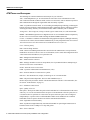
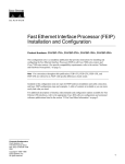
The ATM Cable Interface Processor (ACIP) (see Figure 1) provides a single ATM network interface
for a Cisco 7500 series router by providing a direct connection between the router’s high-speed
Cisco Extended Bus (CyBus) and external equipment. The ACIP can be connected directly to a
TeraLink 1000 cable headend, or through a Cisco Lightstream 1010 ATM switch or other external
ATM network equipment. The physical layer interface module (PLIM) on the ACIP provides a
SONET/SDH (STS-3C) interface connection.
Figure 1
ACIP with the UNI 155-Mbps Interface
RX RX
Ca Ce
rri lls
er
TX
RX
EN
AB
LE
D
UN
I1
55
H2337
U111, microcode ROM
ACIP Features
The ACIP supports the following features:
•
•
•
•
•
Multiple rate queues.
•
Raw queue, which is used for all raw traffic over the ATM network. Raw traffic includes
Operation Administration and Maintenance (OAM) cells and Interim Local Management
Interface (ILMI) cells. (ATM signaling cells are not considered raw.)
Reassembly of up to 512 buffers simultaneously. Each buffer represents a packet.
Up to 2,048 virtual circuits.
Transfer rates per VPI limited to fixed values provided by the cable headend.
Exception queue, which is used for event reporting. Events such as CRC errors are reported to
the exception queue.
4 ATM Cable Interface Processor (ACIP) Installation and Configuration
ACIP Description
ACIP Interface
The ACIP’s ATM interface is full duplex. You must use the appropriate ATM interface cable to
connect the ACIP with external ATM equipment. (Refer to the section “ACIP Cables, PLIM, and
Connections,” on page 7, for descriptions of ATM cables and connectors.) The ACIP provides an
interface to ATM switching fabrics for transmitting and receiving data at rates of up to 155 Mbps
bidirectionally; the actual rate is determined by the PLIM. The ACIP supports a PLIM that connects
to the following physical layer: SONET/SDH 155 Mbps, multimode fiber optic—STS-3C (or
STM-1).
SONET Distance Limitations
The SONET specification for fiber-optic transmission defines two types of fiber: single mode and
multimode; however, the ACIP supports multimode fiber only. Modes can be thought of as bundles
of light rays entering the fiber at a particular angle. Multimode fiber allows multiple modes of light
to propagate through the fiber. Because multiple modes of light propagating through the fiber travel
different distances depending on the entry angles, causing them to arrive at the destination at
different times (a phenomenon called modal dispersion), single-mode fiber is capable of higher
bandwidth and greater cable run distances than multimode fiber.
The typical maximum distances for multimode transmissions, as defined by SONET, are in Table 1.
If the distance between two connected stations is greater than these maximum distances, significant
signal loss can result, making transmission unreliable.
Table 1
SONET Maximum Fiber-Optic Transmission Distances
Transceiver Type
Maximum Distance between Stations1
Multimode
Up to 1.5 miles (3 kilometers)
1. Table 1 gives typical results. You should use the power budget calculations to
determine the actual distances.
Power Budget
To design an efficient optical data link, evaluate the power budget. The power budget is the amount
of light available to overcome attenuation in the optical link and to exceed the minimum power that
the receiver requires to operate within its specifications. Proper operation of an optical data link
depends on modulated light reaching the receiver with enough power to be correctly demodulated.
Attenuation, caused by the passive media components (cables, cable splices, and connectors), is
common to both multimode and single-mode transmission.
The following variables reduce the power of the signal (light) transmitted to the receiver in
multimode transmission:
•
Chromatic dispersion (spreading of the signal in time because of the different speeds of light
wavelengths)
•
Modal dispersion (spreading of the signal in time because of the different propagation modes in
the fiber)
Attenuation is significantly lower for optical fiber than for other media. For multimode transmission,
chromatic and modal dispersion reduce the available power of the system by the combined
dispersion penalty (dB). The power lost over the data link is the sum of the component, dispersion,
and modal losses.
Table 2 lists the factors of attenuation and dispersion limit for typical fiber-optic cable.
ATM Cable Interface Processor (ACIP) Installation and Configuration
5
ACIP Description
Table 2
Typical Fiber-Optic Link Attenuation and Dispersion Limits
Limits
Multimode
Attenuation
1.0 dB/km
Dispersion
500 MHzkm1
1. The product of bandwidth and
distance must be less than 500
MHzkm.
Approximating the ACIP Power Margin
The LED used for a multimode transmission light source creates multiple propagation paths of light,
each with a different path length and time requirement to cross the optical fiber, causing signal
dispersion (smear). Higher order mode loss (HOL) results from light from the LED entering the fiber
and being radiated into the fiber cladding. A worst case estimate of power margin (PM) for
multimode transmissions assumes minimum transmitter power (PT), maximum link loss (LL), and
minimum receiver sensitivity (PR). The worst case analysis provides a margin of error, although not
all of the parts of an actual system will operate at the worst case levels.
The power budget (PB) is the maximum possible amount of power transmitted. The following
equation lists the calculation of the power budget:
PB = PT – PR
PB = –18.5 dBm – (–30 dBm)
PB = 11.5 dB
The power margin calculation is derived from the power budget minus the link loss, as follows:
PM = PB – LL
If the power margin is positive, as a rule, the link will work.
Table 3 lists the factors that contribute to link loss and the estimate of the link loss value attributable
to those factors.
Table 3
Estimating Link Loss
Link Loss Factor
Estimate of Link Loss Value
Higher order mode losses
0.5 dB
Clock recovery module
1 dB
Modal and chromatic dispersion
Dependent on fiber and wavelength used
Connector
0.5 dB
Splice
0.5 dB
Fiber attenuation
1 dB/km
After calculating the power budget minus the data link loss, the result should be greater than zero.
Results less than zero may have insufficient power to operate the receiver.
6 ATM Cable Interface Processor (ACIP) Installation and Configuration
ACIP Description
For the ACIP, the signal must meet the worst case parameters listed in Table 4.
Table 4
ACIP SONET Signal Requirements
Parameter
Multimode
PT
–15
PR
–28
PB
–13
Multimode Power Budget Example with Sufficient Power for Transmission
The following is an example multimode power budget calculated based on the following variables:
•
•
•
•
•
Length of multimode link = 3 kilometers (km)
4 connectors
3 splices
Higher order loss (HOL)
Clock recovery module (CRM)
Estimate the power budget as follows:
PB = 11.5 dB – 3 km (1.0 dB/km) – 4 (0.5 dB) – 3 (0.5 dB) – 0.5 dB (HOL) – 1 dB (CRM)
PB = 11.5 dB – 3 dB – 2 dB – 1.5 dB – 0.5 dB – 1 dB
PB = 3.5 dB
The value of 3.5 dB indicates that this link would have sufficient power for transmission.
Multimode Power Budget Example of Dispersion Limit
Following is an example with the same parameters as the previous example, but with a multimode
link distance of 4 km:
PB = 11.5 dB – 4 km (1.0 dB/km) – 4 (0.5 dB) – 3 (0.5 dB) – 0.5 dB (HOL) – 1 dB (CRM)
PB = 11.5 dB – 4 dB – 2 dB – 1.5 dB – 0.5 dB – 1 dB
PB = 2.5 dB
The value of 2.5 dB indicates that this link would have sufficient power for transmission. But,
because the dispersion limit on the link (4 km x 155.52 MHz > 500 MHzkm), this link would not
work with multimode fiber. In this case, single-mode fiber would be the better choice.
ACIP Cables, PLIM, and Connections
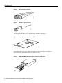
An ACIP interface cable is used to connect your router to an ATM network. For SONET/SDH
(STS-3C) multimode connections, use one multimode duplex SC-type connector (see Figure 2) or
two single SC-type connectors. (See Figure 3.)
ATM Cable Interface Processor (ACIP) Installation and Configuration
7
ACIP Description
Duplex SC-Type Connector
Figure 3
Simplex SC-Type Connector
H2399
H2214
Figure 2
The multimode cable connects to the SC connector on the PLIM. (See Figure 4.)
SONET Multimode SC Duplex PLIM
H2210
Figure 4
The SONET multimode SC-type duplex connector is shipped with a dust plug. (See Figure 5.)
Remove the plug by pulling on the plug as you squeeze its sides.
SONET ATM Multimode Fiber-Optic Transceiver and Dust Plug
H1983
Figure 5
8 ATM Cable Interface Processor (ACIP) Installation and Configuration
ACIP Installation Prerequisites
ACIP Installation Prerequisites
Before you begin the ACIP installation, review the guidelines in this section to ensure a successful
installation, to avoid injuring yourself, or to avoid damaging the equipment. This section also
provides a list of parts and tools you will need to perform the installation.
ACIP Software Prerequisites
To ensure correct operation of the ACIP, Cisco IOS Release 11.2(7)P or later is required.
Hardware and Host Router Prerequisites
The following list describes specific hardware and host router prerequisites:
•
Note that the ACIP is not supported in Cisco 7500 series routers with an RSP4 installed. Only
RSP1s and RSP2s can be used with the ACIP.
•
•
Note that the ACIP is not supported in the Cisco 7000 series routers: Cisco 7000 and Cisco 7010.
You must use the ACIP in the following Cisco 7500 series routers:
— Cisco 7505 (see Figure 6)
— Cisco 7507 (see Figure 7)
— Cisco 7513 (see Figure 8)
The Cisco 7500 series routers provide high reliability, availability, serviceability, and performance,
and supports multiprotocol, multimedia routing, and bridging with a wide variety of protocols and
any combination of available electrical interfaces and media. Network interfaces reside on modular
interface processors (such as the ACIP), which provide a direct connection between the high-speed,
1.067-gigabits-per-second (Gbps) Cisco Extended Bus (CyBus) and external networks. The
Cisco 7507 and Cisco 7513 each have two CyBuses for an aggregate bandwidth of 2.134 Gbps.
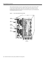
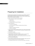
Figure 6 shows the rear of the 5-slot Cisco 7505 router. In the Cisco 7505, one slot (4) is reserved
for the Route Switch Processor (RSP1), which contains the main system processor and performs
packet switching functions. Slots 0 through 3 are for interface processors, including the ACIP.
(There are no restrictions on slot locations or sequence; you can install an ACIP in any available
interface processor slot.)
Cisco 7505, Interface Processor End
T
E
OL
NS
CO
AU
X.
HA
SE
U
RE
CP
T
EC
Interface processor slot 3
EN
AB
EN
LE
AB
LE
EJ
SL SLO
OT T
0 1
AL
RM
NO
RSP slot
ROUTE SWITCH PROCESSOR
LT
Figure 6
Interface processor slot 2
Interface processor slot 1
Interface processor slot 0
H2761
Power switch
Chassis
grounding
receptacles
Power receptacle
DC OK LED
AC-input power supply
ATM Cable Interface Processor (ACIP) Installation and Configuration
9
ACIP Installation Prerequisites
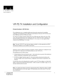
Figure 7 shows the rear of the 7-slot Cisco 7507 router. In the Cisco 7507, up to two slots (2 and 3)
are reserved for the Route Switch Processor (RSP2), which contains the system processor and
performs packet switching functions. Slots 0 and 1, and 4 through 6 are for interface processors,
including the ACIP. (There are no restrictions on slot locations or sequence; you can install an ACIP
in any available interface processor slot.)
Figure 7
Cisco 7507, Interface Processor End
Captive
installation screw
DC
AC
FA
IL
PO
WE
R
EN
NO
AB
RM
LE
AL
Upper
power supply
Chassis
grounding
receptacles
EJ
EC
T
SL SLO
OT T
0 1
I
SL MA
AV ST
E ER
O
SL
AV
E/M
AS
TE
R
Captive
installation screw
CP
U
HA
LT
EN
AB
RE
LE
SE
T
DC
AC
FA
IL
PO
WE
H3888
R
Lower
power supply
AU
X.
NS
OL
E
I
ROUTE SWITCH PROCESSOR 2
CO
O
Slot 0
1
2
3
RSP slots
10 ATM Cable Interface Processor (ACIP) Installation and Configuration
4
5
6
ACIP Installation Prerequisites
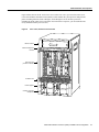
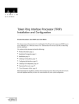
Figure 8 shows the rear of the 13-slot Cisco 7513. In the Cisco 7513, up to two slots (6 and 7) are
reserved for the Route Switch Processor (RSP2), which contains the system processor and performs
packet switching functions. Slots 0 through 5, and 8 through 12 are for interface processors,
including the ACIP. (There are no restrictions on slot locations or sequence; you can install an ACIP
in any available interface processor slot.)
Figure 8
Cisco 7513, Interface Processor End
Blower module
Cable-management
bracket
NO
RM
AL
EN
AB
LE
EJE
CT
SLO SLO
T0 T1
SLA MAS
VE TE
R
Card cage and
processor modules
SLA
VE
/M
AS
TE
R
CP
U
HA
LT
RE
SE
EN
T
AB
LE
AU
X.
ROUTE SWITCH PROCESSOR 2
CO
NS
OLE
Air intake vent
AC
OK
FAN
OK
OUTPUT
FAIL
AC
OK
OUTPUT
FAIL
POWER
A
POWER
B
Chassis grounding
receptacles
H5268
Power supplies
FAN
OK
I
I
0
0
ATM Cable Interface Processor (ACIP) Installation and Configuration
11
ACIP Installation Prerequisites
List of Parts and Tools
You need the following tools and parts to install or upgrade an ACIP. If you need additional
equipment, contact your service representative for ordering information.
•
ACIP-SM(=) and an empty interface processor slot in your Cisco 7500 series router
Note The ACIP is not supported in Cisco 7500 series routers with an RSP4 installed. Only RSP1s
and RSP2s can be used with the ACIP.
•
The appropriate single-mode optical-fiber cable(s) with Simplex or Duplex connections
(optical-fiber cables are not available from Cisco Systems; cables are available from commercial
cable vendors)
•
•
Number 2 Phillips screwdriver or a 3/16-inch flat-blade screwdriver
•
ESD cord and wrist strap or disposable wrist strap that shipped with the ACIP
Appropriate multimode optical-fiber cable (not available from Cisco Systems) to connect the
ACIP with the ATM network
Safety Guidelines
This section lists safety guidelines to follow when working with any equipment that connects to
electrical power or telephone wiring.
Safety Warnings
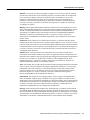
Safety warnings appear throughout this publication in procedures that, if performed incorrectly,
might harm you. A warning symbol precedes each warning statement.
Warning Means danger. You are in a situation that could cause bodily injury. Before you work on
any equipment, be aware of the hazards involved with electrical circuitry and be familiar with
standard practices for preventing accidents. To see translations of the warnings that appear in this
publication, refer to the Regulatory Compliance and Safety Information document that accompanied
this device.
Waarschuwing Dit waarschuwingssymbool betekent gevaar. U verkeert in een situatie die
lichamelijk letsel kan veroorzaken. Voordat u aan enige apparatuur gaat werken, dient u zich bewust
te zijn van de bij elektrische schakelingen betrokken risico's en dient u op de hoogte te zijn van
standaard maatregelen om ongelukken te voorkomen. Voor vertalingen van de waarschuwingen die
in deze publicatie verschijnen, kunt u het document Regulatory Compliance and Safety Information
(Informatie over naleving van veiligheids- en andere voorschriften) raadplegen dat bij dit toestel is
ingesloten.
Varoitus Tämä varoitusmerkki merkitsee vaaraa. Olet tilanteessa, joka voi johtaa ruumiinvammaan.
Ennen kuin työskentelet minkään laitteiston parissa, ota selvää sähkökytkentöihin liittyvistä
vaaroista ja tavanomaisista onnettomuuksien ehkäisykeinoista. Tässä julkaisussa esiintyvien
varoitusten käännökset löydät laitteen mukana olevasta Regulatory Compliance and Safety
Information -kirjasesta (määräysten noudattaminen ja tietoa turvallisuudesta).
12 ATM Cable Interface Processor (ACIP) Installation and Configuration
ACIP Installation Prerequisites
Attention Ce symbole d'avertissement indique un danger. Vous vous trouvez dans une situation
pouvant causer des blessures ou des dommages corporels. Avant de travailler sur un équipement,
soyez conscient des dangers posés par les circuits électriques et familiarisez-vous avec les
procédures couramment utilisées pour éviter les accidents. Pour prendre connaissance des
traductions d’avertissements figurant dans cette publication, consultez le document Regulatory
Compliance and Safety Information (Conformité aux règlements et consignes de sécurité) qui
accompagne cet appareil.
Warnung Dieses Warnsymbol bedeutet Gefahr. Sie befinden sich in einer Situation, die zu einer
Körperverletzung führen könnte. Bevor Sie mit der Arbeit an irgendeinem Gerät beginnen, seien Sie
sich der mit elektrischen Stromkreisen verbundenen Gefahren und der Standardpraktiken zur
Vermeidung von Unfällen bewußt. Übersetzungen der in dieser Veröffentlichung enthaltenen
Warnhinweise finden Sie im Dokument Regulatory Compliance and Safety Information
(Informationen zu behördlichen Vorschriften und Sicherheit), das zusammen mit diesem Gerät
geliefert wurde.
Avvertenza Questo simbolo di avvertenza indica un pericolo. La situazione potrebbe causare
infortuni alle persone. Prima di lavorare su qualsiasi apparecchiatura, occorre conoscere i pericoli
relativi ai circuiti elettrici ed essere al corrente delle pratiche standard per la prevenzione di incidenti.
La traduzione delle avvertenze riportate in questa pubblicazione si trova nel documento Regulatory
Compliance and Safety Information (Conformità alle norme e informazioni sulla sicurezza) che
accompagna questo dispositivo.
Advarsel Dette varselsymbolet betyr fare. Du befinner deg i en situasjon som kan føre til
personskade. Før du utfører arbeid på utstyr, må du vare oppmerksom på de faremomentene som
elektriske kretser innebærer, samt gjøre deg kjent med vanlig praksis når det gjelder å unngå ulykker.
Hvis du vil se oversettelser av de advarslene som finnes i denne publikasjonen, kan du se i
dokumentet Regulatory Compliance and Safety Information (Overholdelse av forskrifter og
sikkerhetsinformasjon) som ble levert med denne enheten.
Aviso Este símbolo de aviso indica perigo. Encontra-se numa situação que lhe poderá causar danos
físicos. Antes de começar a trabalhar com qualquer equipamento, familiarize-se com os perigos
relacionados com circuitos eléctricos, e com quaisquer práticas comuns que possam prevenir
possíveis acidentes. Para ver as traduções dos avisos que constam desta publicação, consulte o
documento Regulatory Compliance and Safety Information (Informação de Segurança e
Disposições Reguladoras) que acompanha este dispositivo.
¡Advertencia! Este símbolo de aviso significa peligro. Existe riesgo para su integridad física.
Antes de manipular cualquier equipo, considerar los riesgos que entraña la corriente eléctrica y
familiarizarse con los procedimientos estándar de prevención de accidentes. Para ver una traducción
de las advertencias que aparecen en esta publicación, consultar el documento titulado Regulatory
Compliance and Safety Information (Información sobre seguridad y conformidad con las
disposiciones reglamentarias) que se acompaña con este dispositivo.
Varning! Denna varningssymbol signalerar fara. Du befinner dig i en situation som kan leda till
personskada. Innan du utför arbete på någon utrustning måste du vara medveten om farorna med
elkretsar och känna till vanligt förfarande för att förebygga skador. Se förklaringar av de varningar
som förkommer i denna publikation i dokumentet Regulatory Compliance and Safety Information
(Efterrättelse av föreskrifter och säkerhetsinformation), vilket medföljer denna anordning.
ATM Cable Interface Processor (ACIP) Installation and Configuration
13
ACIP Installation Prerequisites
Electrical Equipment
Follow these basic guidelines when working with any electrical equipment:
•
Before beginning any procedures requiring access to the chassis interior, locate the emergency
power-off switch for the room in which you are working.
•
Disconnect all power and external cables before moving a chassis; do not work alone if
potentially hazardous conditions exist.
•
•
•
Never assume that power is disconnected from a circuit; always check.
Do not perform any action that creates a potential hazard to people or makes equipment unsafe.
Carefully examine your work area for possible hazards such as moist floors, ungrounded power
extension cables, and missing safety grounds.
Telephone Wiring
Use the following guidelines when working with any equipment that is connected to telephone
wiring or to other network cabling:
•
•
Never install telephone wiring during a lightning storm.
•
Never touch uninsulated telephone wires or terminals unless the telephone line has been
disconnected at the network interface.
•
Use caution when installing or modifying telephone lines.
Never install telephone jacks in wet locations unless the jack is specifically designed for wet
locations.
Preventing Electrostatic Discharge Damage
Electrostatic discharge (ESD) damage, which can occur when electronic cards or components are
improperly handled, results in complete or intermittent failures. An ACIP comprises a printed circuit
board that is fixed in a metal carrier. Electromagnetic interference (EMI) shielding, connectors, and
a handle are integral components of the carrier. Although the metal carrier helps to protect the board
from ESD, always use a preventive antistatic strap when handling an ACIP. Handle the carriers by
the handles and the carrier edges only; never touch the boards or connector pins.
Caution Always tighten the captive installation screws on an ACIP. (See Figure 1.) These screws
prevent accidental removal, provide proper grounding for the system, and help ensure that the bus
connectors are properly seated in the backplane.
Following are guidelines for preventing ESD damage:
•
•
Always use an ESD wrist or ankle strap and ensure that the strap makes good skin contact.
•
When installing an ACIP, use the ejector levers to properly seat the bus connectors in the
backplane, then tighten both (top and bottom) captive installation screws. (See Figure 1.) These
screws prevent accidental removal, provide proper grounding for the system, and help to ensure
that the bus connectors are seated in the backplane.
Connect the equipment end of the strap to a captive installation screw on an installed power
supply.
14 ATM Cable Interface Processor (ACIP) Installation and Configuration
ACIP Installation Prerequisites
•
When removing an ACIP, use the ejectors to release the bus connectors from the backplane. Hold
the handle on the front of an ACIP with one hand and support the bottom edge of the metal carrier
with the other hand. Pull the carrier out slowly, using your hand along the bottom of the carrier
to guide an ACIP straight out of the slot.
•
Handle carriers by the handles and carrier edges only; avoid touching the board or any connector
pins.
•
Place a removed ACIP board-side-up on an antistatic surface or in a static shielding bag. If the
component will be returned to the factory, immediately place an ACIP in a static shielding bag.
•
Avoid contact between an ACIP and clothing. The wrist strap only protects the board from ESD
voltages on the body; ESD voltages on clothing can still cause damage.
For safety, periodically check the resistance value of the antistatic strap. The
measurement should be between 1 and 10 megohms.
Caution
ATM Cable Interface Processor (ACIP) Installation and Configuration
15
Installing and Removing an ACIP
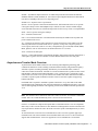
Installing and Removing an ACIP
An ACIP slides into slots in the rear of a Cisco 7500 series chassis and connects directly to the
backplane. The backplane slots are keyed so that the ACIP can be installed only in the slots
designated for it. (For interface processor slot locations, refer to section “Hardware and Host Router
Prerequisites” on page 9.) Figure 9 shows the procedures for removing and installing an ACIP.
When tightened, the captive installation screws on the ends of the ACIP faceplate help ensure proper
seating in the backplane. After using the ejector levers to install an ACIP, immediately tighten the
captive installation screws to prevent an ACIP from becoming partially dislodged from the
backplane, and before installing additional processors; this will help reduce the effects of EMI.
Failure to use ejector levers could result in a partial backplane connection, which can
hang the system.
Caution
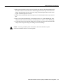
Figure 9
Installing and Removing an ACIP
Card carrier guide (black)
Remove a module as follows:
1. Use a screwdriver to loosen the captive installation
screws (shown in A).
A
2. Simultaneously pull the ejector levers out to release
the module from the backplane connector (shown in B).
The levers should snap into their spring retainers.
Captive
installation
screw
B
3. Grasp the module handle with one hand and place your
other hand under the carrier to support and guide the
module as you pull it out of the slot. Avoid touching the card.
4. Place the removed module on an antistatic mat or antistatic
foam, or immediately install it in another slot.
5. Install a new module or a filler (MAS7K-BLANK) to keep
dust out of the chassis and to maintain proper airflow
through the chassis.
Install a module as follows:
1. Choose a slot for the new module and ensure that there is
enough clearance to accommodate any interface equipment
that you will connect directly to its ports.
C
2. Use a screwdriver to loosen the captive installation screws
(shown in A) and remove the filler (or the existing module)
from the slot to be filled.
3. Hold the module handle with one hand, and place your
other hand under the carrier to support the module and guide
it into the slot. Avoid touching the card.
4. Place the back of the module in the slot and align the guide
on the carrier with the groove in the slot (shown in A).
5. Carefully slide the module into the slot until the faceplate
makes contact with the ejector levers (shown in C).
7. Use a screwdriver to tighten the captive installation screws.
16 ATM Cable Interface Processor (ACIP) Installation and Configuration
H2620
6. Use the thumb and forefinger of each hand to push the
ejector lever flat against the module (shown in B).
Attaching Network Interface Cables to the ACIP
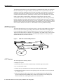
Attaching Network Interface Cables to the ACIP
The ACIP interfaces are full duplex. You must use the appropriate ATM interface cable to connect
the ASIP to your TeraLink 1000, either directly, or through an external ATM network.
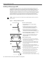
Connect cables to the ACIP as shown in Figure 10.
Figure 10
Connecting Cables to the ACIP (Vertical Orientation Shown)
SONET/SDH with simplex
or duplex SC connectors
Simplex (2)
To a TeraLink 1000
ACIP
H10446
Duplex (1)
Warning Invisible laser radiation may be emitted from the aperture ports of the single-mode
products when no fiber cable is connected. Avoid exposure and do not stare into open apertures.
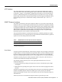
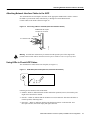
Using LEDs to Check ACIP Status
The ACIP has three status LEDs on its faceplate (see Figure 11).
LE
AB
H2417
EN
RX RX
Ca Ce
rri lls
er
ACIP LEDs (Partial Faceplate View, Horizontal Orientation)
D
Figure 11
Following are the functions of the ACIP LEDs:
•
Enabled—When on, indicates that the ACIP is enabled for operation; however, the interface ports
might not be functional or enabled.
•
RX cells —When on, indicates that the ACIP has received an ATM cell. This LED will flicker in
normal operation, indicating traffic.
•
RX carrier —When on, indicates that the ACIP has detected carrier on the RX cable. For a
fiber-optic interface, this means simply that light is detected.
ATM Cable Interface Processor (ACIP) Installation and Configuration
17
Using LEDs to Check ACIP Status
After you install the ACIP and attach the interface cable between the ACIP’s interface port and your
cable headend (TeraLink 1000) or external ATM switch, verify the installation by observing the LED
states and the console display.
When the system has reinitialized all interfaces, the enabled LED on the ACIP should go on. The
console screen will also display a message as the system discovers each interface during its
reinitialization. After system initialization, the enabled LED, which is present on all interface
processors, goes on to indicate that the ACIP is enabled for operation.
The following conditions must be met before the ACIP is enabled:
•
•
•
The ACIP is correctly connected to the backplane and receiving power.
The CyBus recognizes the ACIP card.
A valid version of ACIP microcode is loaded and running.
If any of these conditions is not met, the enabled LED does not go on.
Verify that the ACIP is installed correctly as follows:
Step 1
While the system reinitializes each interface, observe the console display messages and
verify that the system discovers the ACIP as follows:
•
If you installed a new ACIP, the system should recognize the new ATM interface but
leave the interface configured as down.
•
If you replaced an ACIP, the system should recognize the interface and put the
interface into the same state (up or down) the interface had when you removed it.
Step 2
When the reinitialization is complete, verify that the enabled LED on the ACIP is on and
remains on. If the LED does stay on, proceed to step 5. If the enabled LED does not stay
on, proceed to the next step.
Step 3
If the enabled LED on the ACIP fails to go on, suspect that the ACIP board connector is
not fully seated in the backplane. Loosen the captive installation screws, then firmly push
the top ejector down while pushing the bottom ejector up until both are at a 90-degree
orientation to the ACIP faceplate. Tighten the captive installation screws. After the
system reinitializes the interfaces, the enabled LED on the ACIP should go on. If the
enabled LED goes on, proceed to step 5. If the enabled LED does not go on, proceed to
the next step.
Step 4
If the enabled LED still fails to go on, remove the ACIP and try installing it in another
available interface processor slot.
Step 5
•
If the enabled LED goes on when the ACIP is installed in the new slot, suspect a failed
backplane port in the original interface processor slot.
•
If the enabled LED still fails to go on, but other LEDs on the ACIP go on to indicate
activity, proceed to step 5 to resume the installation checkout and suspect that the
enabled LED on the ACIP has failed.
•
•
If no LEDs on the ACIP go on, suspect that the ACIP is faulty.
If the enabled LED still does not go on, do not proceed with the installation. Contact
a customer service representative to report the faulty equipment and obtain further
instructions.
If the ATM interface is new, proceed to the section “Configuring the ACIP, ” on page 21,
to configure the new interface. (The interface is not available until you configure it.)
18 ATM Cable Interface Processor (ACIP) Installation and Configuration
Using show Commands to Verify Interface Status
Step 6
If this installation was a replacement ACIP, use the show interfaces or show controllers
cbus command to verify the status of the ATM interface. (For command descriptions and
examples, refer to the section “Using show Commands to Verify Interface Status” on
page 19.)
Step 7
When the interface is up, check the activity of the interface with the ACIP LEDs.
(See Figure 11.)
If an error message displays on the console terminal, refer to the appropriate reference publication
for error message definitions. If you experience other problems that you are unable to solve, contact
a service representative for assistance.
This completes the procedure for checking initial ACIP status.
Using show Commands to Verify Interface Status
The show version command displays the current hardware configuration of the router, including the
system software version that is currently loaded and running. The show controller cbus command
lists all interfaces and includes the currently loaded and running microcode version for each. The
show diagbus slot command shows the hardware and board revision of an interface processor in a
designated interface processor slot.
Use the show version command to display the current system software version. In the following
example of the show version command, the running system software is Release 11.2(7)P:
Router# show version
Cisco Internetwork Operating System Software
IOS (tm) RSP Software (RSP-ITV-M), Released Version 11.2(7)P [biff 265]
Copyright (c) 1986-1997 by cisco Systems, Inc.
Compiled Mon 24-Feb-97 17:20 by biff
Image text-base: 0x600108A0, data-base: 0x606D4000
ROM: System Bootstrap, Version 5.3(16645) [biff 571], RELEASE SOFTWARE
ROM: RSP Software (RSP-BOOT-M), Version 11.2(7)P, RELEASE SOFTWARE (fc1)
Router uptime is 1 day, 18 hours, 42 minutes
System restarted by reload
System image file is “biff/rsp-itv-mz”, booted via tftp from 1.1.1.10
cisco RSP2 (R4600) processor with 32768K bytes of memory.
R4600 processor, Implementation 32, Revision 2.0
Last reset from power-on
G.703/E1 software, Version 1.0.
Bridging software.
X.25 software, Version 2.0, NET2, BFE and GOSIP compliant.
Chassis Interface.
(additional displayed text not shown)
1 ACIP controller (1 ATM).
1 ATM network interface(s)
(additional displayed text not shown)
125K bytes of non-volatile configuration memory.
8192K bytes of Flash PCMCIA card at slot 0 (Sector size 128K).
8192K bytes of Flash internal SIMM (Sector size 256K).
No slave installed in slot 3.
Configuration register is 0x100
ATM Cable Interface Processor (ACIP) Installation and Configuration
19
Using show Commands to Verify Interface Status
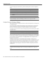
Following is an example of the show controller cbus display. Note the display of the ACIP’s
microcode version (20.2), PLIM type (SONET), and available bandwidth (155 Mbps).
Router# show cont cbus
MEMD at 40000000, 2097152 bytes (unused 2912, recarves 1, lost 0)
RawQ 48000100, ReturnQ 48000108, EventQ 48000110
BufhdrQ 48000120 (2961 items), LovltrQ 48000138 (2 items, 1632 bytes)
IpcbufQ_classic 48000140 (8 items, 4096 bytes)
3570 buffer headers (48002000 - 4800FF10)
pool0: 12 buffers, 256 bytes, queue 48000128
pool1: 244 buffers, 1536 bytes, queue 48000130
pool2: 339 buffers, 4544 bytes, queue 48000148
pool3: 4 buffers, 4576 bytes, queue 48000150
(additional displayed text not shown)
slot5: ACIP, hw 1.3, sw 20.2, ccb 5800FF70, cmdq 480000A8, vps 8192
software loaded from system
ATM3/0, applique is SONET (155Mbps)
gfreeq 48000148, lfreeq 480001C8 (4544 bytes), throttled 0
rxlo 4, rxhi 339, rxcurr 0, maxrxcurr 2
txq 480001D0, txacc 480000BA (value 226), txlimit 226
If the display indicates that the ACIP’s microcode is an earlier version than 205.02, check the
contents of Flash memory to determine if the required images are available on your system. (The
show flash command displays a list of all files stored in Flash memory.)
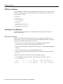
Use the show diagbus slot command to determine if your ACIP is recognized by the system and to
verify its hardware and board revision. Following is an example:
Router# show diagbus 3
Slot 3:
Physical slot 3, ~physical slot 0x8, logical slot 3, CBus 0
Microcode Status 0xB
Master Enable, LED, WCS Loaded
Board is analyzed
EEPROM format version 1
ATM Cable Interface Processor, HW rev 1.3, board revision B0
Serial number: 03177260 Part number: 73-1188-03
Test history: 0x00
RMA number: 00-00-00
Flags: cisco 7000 board; 7500 compatible
EEPROM contents (hex):
0x20: 01 08 81 03 00 30 7B 2C 49 04 A4 03 00 00 00 00
0x30: 58 00 00 00 FF 00 00 00 00 00 00 00 00 00 00 00
Slot database information:
Flags: 0x4
Insertion time: 0x5DC (1d18h ago)
This completes the ACIP installation and installation checks. If you installed a new ACIP, you must
now configure the new interface, as described in the following section.
20 ATM Cable Interface Processor (ACIP) Installation and Configuration
Configuring the ACIP
Configuring the ACIP
Configuring the ACIP is a two step process: first you configure the ACIP, then you configure the
cable headend and/or ATM switch. To configure ATM, complete the following tasks. The first two
tasks are required, and then you must configure at least one PVC or SVC. The VC options you
configure must match in three places: on the router, on the ATM switch, and at the remote end of the
PVC or SVC connection.
•
•
•
Enable the ACIP.
Configure cable parameters.
Monitor and maintain the ATM interface (optional).
Note To configure your TeraLink 1000 cable headend and/or ATM switch, refer to the appropriate
product’s user documentation.
Perform the tasks in the following sections to configure the ACIP interface (all tasks are required
except for the last task):
•
•
•
•
•
•
Configure an ACIP Interface, page 22
Configure Cable Parameters, page 23
Configure the Integrated Routing and Bridging Feature, page 23
Configure the Bridge-Group Virtual Interface, page 23
Configure Protocols for Routing or Bridging, page 24
Monitor and Maintain the ACIP, page 25
Note After you configure the ACIP, you must configure the cable headend and/or ATM switch.
For information on additional commands that can be used with the ACIP, refer to the Cisco IOS
Release 11.2(7)P feature guide. For an example ACIP configuration, refer to the section
“Configuration Example” on page 25.
ATM Cable Interface Processor (ACIP) Installation and Configuration
21
Configuring the ACIP
Configure an ACIP Interface
The ACIP interface (or subinterface) uses the configuration defaults shown in Table 1. For
information on how to change the defaults, refer to the “Configuring ATM” chapter of the Wide-Area
Networking Configuration Guide and the “Configuring Interfaces” chapter of the Configuration
Fundamentals Configuration Guide. All ATM and interface commands might not be applicable to
the ACIP interface.
Note If a command is not available, the router displays the message “Command not supported on
this interface.”
Table 1
ACIP Defaults
Parameter
Command
Default Value
Maximum transmission unit
mtu bytes
4470
Exception queue buffers
atm exception queue number
32
Receive buffers
atm rxbuff number
256
Transmit buffers
atm txbuff number
256
Maximum number of virtual
circuits (VCs)
atm maxvc number
2048
ATM raw cell queue size
atm rawq-size number
32
ATM VCs per VP
atm vc-per-vp number
1024
Source of Transmit Clock
atm clock internal
Recovered receive clock
To configure the ATM interface on the ACIP, perform the following tasks beginning in global
configuration mode:
Task
Command
1
Step 1
Assign a bridge group.
bridge bridge-group protocol {dec | ieee}
Step 2
Specify the interface and enter interface
configuration mode.
interface atm slot/02
Step 3
Assign the bridge group to the interface.
bridge-group number
Step 4
Disable the spanning tree on the interface.
bridge-group number spanning-disabled
Step 5
Change the shutdown state to up and enable
the interface.
no shutdown
1. For more information on creating bridge groups, refer to the “Configuring Transparent Bridging” chapter
of the Bridging and IBM Network Configuration Guide.
2. Because the ACIP contains a single interface, the port number is always 0.
22 ATM Cable Interface Processor (ACIP) Installation and Configuration
Configuring the ACIP
Configure Cable Parameters
To assign the ATM interface on the ACIP to a cable headend and specify the cable headend IP
address, perform the following tasks beginning in global configuration mode:
Task
Command
Step 1
Specify the ATM interface, VPI, and headend
IP address.
cable bind interface vpi ip-address
Step 2
Optionally, enable proxy-ARP handling if
user-to-user communication is permitted for
each channel.
cable enable-proxy interface vpi
Note The Cisco IOS software automatically adds the bridge number aging-time 604800 to the
configuration file.
Configure the Integrated Routing and Bridging Feature
After you have set up the interfaces in the router, you can enable integrated routing and bridging.
To enable integrated routing and bridging, perform the following task in global configuration mode:
Task
Command
Enable integrated routing and bridging.
bridge irb
Use the show interfaces irb privileged EXEC command to display the protocols that a given bridged
interface can route to the other routed interface when the packet is routable, and to display the
protocols that a given bridged interface bridges.
Note For more information on the integrated routing and bridging feature, refer to the “Configuring
Transparent Bridging” chapter of the Bridging and IBM Network Configuration Guide.
Configure the Bridge-Group Virtual Interface
The bridge-group virtual interface resides in the router. It acts like a normal routed interface that does
not support bridging, but represents the entire corresponding bridge group to routed interfaces within
the router. The bridge-group virtual interface is assigned the number of the bridge group that it
represents. The bridge-group virtual interface number is the link between the bridge-group virtual
interface and its bridge group. Because the bridge-group virtual interface is a virtual routed interface,
it has all the network layer attributes, such as a network address and the ability to perform filtering.
Only one bridge-group virtual interface is supported for each bridge group.
When you enable routing for a given protocol on the bridge-group virtual interface, packets coming
from a routed interface but destined for a host in a bridged domain are routed to the bridge-group
virtual interface, and are forwarded to the corresponding bridged interface. All traffic routed to the
bridge-group virtual interface is forwarded to the corresponding bridge group as bridged traffic. All
routable traffic received on a bridged interface is routed to other routed interfaces as if it is coming
directly from the bridge-group virtual interface.
ATM Cable Interface Processor (ACIP) Installation and Configuration
23
Configuring the ACIP
To create a bridge-group virtual interface, perform the following tasks in interface configuration
mode:
Task
Command
Step 1
Enable a bridge-group virtual interface.
interface bvi bridge-group
Step 2
Specify the IP address for the interface.
ip address ip-address mask
Step 3
Disable the sending of redirect messages.
no ip redirects
Step 4
Optionally, enable fast-switching on the
interface.
ip route-cache same-interface
Note For more information on bridge-group virtual interfaces, refer to the “Configuring
Transparent Bridging” chapter of the Bridging and IBM Network Configuration Guide.
Configure Protocols for Routing or Bridging
When integrated routing and bridging is enabled, the default route/bridge behavior in a bridge group
is to bridge all packets.
You can then explicitly configure the bridge group to route a particular protocol, so that routable
packets of this protocol are routed, while non-routable packets of this protocol or packets for
protocols for which the bridge group is not explicitly configured to route will be bridged.
To configure specific protocols to be routed in a bridge group, perform the following task in global
configuration mode:
Task
Command
Specify the IP protocol to be routed in a bridge group.
bridge bridge-group route ip
When you intend to bridge and route a given protocol in the same bridge group, you must configure
the network-layer attributes of the protocol on the bridge-group virtual interface. Do not configure
protocol attributes on the bridged interfaces. No bridging attributes can be configured on the
bridge-group virtual interface.
Although it is generally the case that all bridged segments belonging to a bridge group are
represented as a single segment or network to the routing protocol, there are situations where several
individual networks coexist within the same bridged segment. To make it possible for the routed
domain to learn about the other networks behind the bridge-group virtual interface, configure a
secondary address on the bridge-group virtual interface to add the corresponding network to the
routing process.
Note For more information on the protocols to be routed in a bridge group, refer to the
“Configuring Transparent Bridging” chapter of the Bridging and IBM Network Configuration
Guide.
24 ATM Cable Interface Processor (ACIP) Installation and Configuration
Configuring the ACIP
Monitor and Maintain the ACIP
After configuring the new interface, you can display its status. You can also display the current status
of connections and active modems on each interface. To show current status information, perform
the following tasks in EXEC mode:
Task
Command
Display the configured cable channels status.
show cable channel
Display the active modems.
show cable modem
Display the ATM interface status.
show interface atm slot/number
Display the BVI interface status.
show interface bvi slot/number
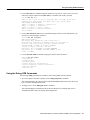
Configuration Example
This section contains an example that shows how to configure the ACIP interface; it also shows other
Cisco IOS commands required for the ACIP to connect to a cable headend (modem).
Each ATM virtual circuit carries data for a single subscriber cable data modem. Data sent over this
interface is first encapsulated in Ethernet frames and then encapsulated in AAL5 CPCS-PDU (per
RFC 1483 LLC SNAP Encapsulation of Bridged Protocols). To support encapsulation, the router
must operate as an integrated router/bridge by using the bridge irb command and the bridge-group
virtual interface (interface bvi command). The bridge-group virtual interface decapsulates the
Ethernet packets received from the ATM interface and multiplexes the router interface to multiple
VCs. No actual bridging is performed between VCs.
All of the IP devices on each of the Ethernet interfaces of the subscriber cable data modem must be
on the same IP subnet. The router, in general, will not perform an ARP to find MAC addresses of
hosts; instead, the router will assume that DHCP is used by each host. Because entries in the ARP
table must not age out normally, the software automatically adds the bridge number aging-time
604800 command to the configuration file.
Data from one host to another on the same cable channel must be sent via the router. The router
knows that two hosts are both on the same subnet and would normally send an ICMP redirect to
inform the first host that a better path exists. However, because the cable media does not support
direct host-to-host communications, the router must do the forwarding, and the ICMP must be
suppressed with the no ip redirects command.
The cable bind command specifies the headend IP address (1.1.1.2), and the BVI interface specifies
the local IP address (1.1.1.1).
Router(config)# interface atm 5/0
Router(config-if)# bridge-group 1
Router(config-if)# bridge-group 1 spanning-disable
Router(config-if)# no shutdown
Router(config-if)# exit
Router(config)# cable bind atm 5/0 17 1.1.1.2
Router(config)# bridge irb
Router(config)# interface bvi 1
Router(config-if)# ip address 1.1.1.1 255.255.255.0
Router(config-if)# no ip redirects
Router(config-if)# exit
Router(config)# bridge 1 protocol dec
Router(config)# bridge 1 route ip
Router(config)# exit
ATM Cable Interface Processor (ACIP) Installation and Configuration
25
ACIP Error Statistics
ACIP Error Statistics
The ACIP maintains a count of certain errors. In addition to keeping a count of these errors, the ACIP
also takes a snapshot of the last VCI/VPI that caused the error. Each ACIP error counter is 16 bits.
Errors include the following:
•
•
•
•
•
•
CRC errors
Giants received
No buffers available
Framing errors
Applique/physical layer errors
Packet timeout errors on receive
Checking the Configuration
After configuring the new interface, use the show commands to display the status of the new
interface or all interfaces.
ATM show Commands
In addition to the show commands described in the section “Using show Commands to Verify
Interface Status,” on page 19, you can use the following additional show commands to display the
current state of the ATM network and the connected VCs:
•
To show current VCs and traffic information, use the show atm vc [vcd] command:
Specifying a VCD will display specific information about that VCD.
•
To show current ATM-specific information about an interface, use the show atm int interface
command:
•
To show current ATM traffic, use the show atm traffic command:
This command displays global traffic information to and from all ATM networks connected to
the router.
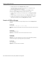
Following are descriptions and examples of the preceding show commands:
•
Use the show atm vc command to display the following types of statistics for all VCs:
Router# show atm vc
Interface
ATM3/0.1
ATM3/0.1
VCD
1
2
VPI
16
16
VCI Type
32 PVC
33 PVC
AAL /
Encapsulation
AAL5-SNAP
AAL5-SNAP
26 ATM Cable Interface Processor (ACIP) Installation and Configuration
Peak
Kbps
8192
8192
Avg. Burst
Kbps Cells Status
8192 1024 ACTIVE
8192 1024 ACTIVE
Using the Debug ATM Commands
•
Use the show atm vc n command to display statistics for a given PVC, where n is the VCD. The
following is sample output from the show atm vc n command, with VCD 1 specified:
Router# show atm vc 1
ATM3/0.1: VCD: 1, VPI: 16, VCI: 32, etype:0x0, AAL5 - LLC/SNAP, Flags: 0x130
PeakRate: 8192, Average Rate: 8192, Burst Cells: 1024, VCmode: 0xE200
OAM DISABLED, InARP DISABLED
InPkts: 0, OutPkts: 9, InBytes: 0, OutBytes: 630
InPRoc: 0, OutPRoc: 9, Broadcasts: 0
InFast: 0, OutFast: 0, InAS: 0, OutAS: 0
OAM F5 cells sent: 0, OAM cells received: 0
Status: ACTIVE
•
Use the show interfaces atm slot/port command to display statistics for the ATM interface you
specify by its slot/port address as follows:
Router# show atm int ATM3/0
ATM interface ATM3/0:
AAL enabled: AAL5, Maximum VCs: 2048, Current VCCs: 2
Tx buffers 256, Rx buffers 256, Exception Queue: 32, Raw Queue: 32
VP Filter: 0x7B, VCIs per VPI: 1024, Max. Datagram Size:4496
PLIM Type:SONET - 155Mbps, TX clocking: INTERNAL
2 input, 18 output, 0 IN fast, 0 OUT fast
Rate-Queue 0 set to 10000Kbps, reg=0x42B PERMANENT
Rate-Queue 1 set to 8192Kbps, reg=0x5BE DYNAMIC, 2 VCCs
Config. is ACTIVE
•
Use the show atm traffic command to display the interface traffic as follows:
Router# show atm traffic
2 Input packets
18 Output packets
9 Broadcast packets
0 Packets received on non-existent VC
0 Packets attempted to send on non-existent VC
0 OAM cells received
0 OAM cells sent
Using the Debug ATM Commands
The following debug commands are available to aid in solving ATM network problems:
•
To create a dump of all protocol packets, use the debug atm packet command:
This command displays the contents of the SNAP/NLPID/SMDS header followed by the first 40
bytes of a packet in hexadecimal format.
•
To display errors, use the debug atm errors command:
This command displays information from all detected ATM errors; including such errors as
encapsulation failures and errors during ATM configuration.
ATM Cable Interface Processor (ACIP) Installation and Configuration
27
Examples of ATM Error Messages
•
To display ATM events, use the debug atm events command:
This command displays event changes to the ACIP. Reset, VC configurations, ACIP
configurations, and PLIM failures are displayed.
After you use a debug command, turn off debugging with the no debug command.
Following are additional debug commands specifically related to the ACIP:
•
To display changes in connectivity to the TeraLink system, use the debug cable channel
command.
•
•
To display changes in subscriber modem status, use the debug cable modem command.
To display error messages that are caused by unexpected system behavior or problems
connecting to the Teralink system, use the debug cable error command.
Examples of ATM Error Messages
Following is a list of possible error messages displayed when you enter the debug atm event
command:
Error Message
RESET(ATM2/0): PLIM type is 0, Rate is 0Mbps
Explanation Displays the PLIM TYPE value returned from the ACIP and the expected associated
rate.
Error Message
AIP_disable(ATM2/0): state=1
Explanation The DISABLE code to shut the ACIP down has been entered.
Error Message
config(ATM2/0)
Explanation The current configuration to the ACIP was sent including TXBUFF, RXBUFF,
exception queue length, raw queue length, and rate queue information.
Error Message
AIP_enable(ATM2/0)
Explanation The ACIP is taken out of shutdown.
28 ATM Cable Interface Processor (ACIP) Installation and Configuration
Examples of ATM Error Messages
Error Message
AIP_love_note(ATM2/0): asr=0xaaaa
Explanation Received a love note from the ACIP. Love notes are messages that the ACIP passes to
the RSP to indicate an action or event has taken place. For example, the ACIP signals the RSP with
a love note when the ACIP completes a VC setup/teardown request. Another love note signals to the
RSP that CD sense has changed. The ASR is a bit mask that defines the actions that might have taken
place. The ASR values are different for all the interfaces. Of the following bit mask values, only
0x4000, which singles CD state changes, is consistent between the different interfaces:
•
•
•
•
0x8000—IP panic
0x4000—CD state change
0x200—Command to ACIP has completed
0x00n0—Completion status of a command (0... 9) 0 is OK; a value of >0 indicates failure
All other values of the ASR are meaningless and discarded. The love note messages only show up
if debug atm event is turned on.
Error Message
AIP_cstate(ATM2/0): state=1
Explanation The state of the device is changed to either UP(1) or DOWN(0).
Error Message
AIP_setup_vc(ATM2/0): vc:1 vpi:0 vci:7
Explanation
A VC SETUP request is being sent to the ACIP to establish a VC.
Error Message
AIP_setup_vc(ATM2/0): vc1 creation delayed, ACIP config. in progress
Explanation The SETUP VC request is being delayed to allow the ACIP to come up and configure
itself.
Error Message
AIP_teardown_vc(ATM2/0): vc:1 vpi:0 vci:
Explanation A VC teardown is requested. The VC is being deconfigured.
Error Message
AIP_enable(ATM2/0): restarting VCs: 5
Explanation All previously configured PVCs are being reconnected on the ACIP.
ATM Cable Interface Processor (ACIP) Installation and Configuration
29
Examples of ATM Error Messages
Following is a list of possible error messages displayed when you enter the debug atm errors
command:
Error Message
AIP_love_note(ATM2/0): UNKNOWN asr=0x0000
Explanation A bad love note message was passed back by the ACIP.
Error Message
AIP_setup_vc(ATM2/0): TIQ err. VC 1 peak 1000 avg. 1 rateq rate 2
Explanation Indicates that a VC SETUP failed because the average rate requested could not be
configured on the ACIP. The average rate is far too low compared to the peak rate.
Error Message
AIP_setup_vc(ATM2/0): CQ err. VC 1 CQ=2048 MTU=256000
This error message indicates that the cell quota selected is out of the range allowed
by the ACIP. In the case of PVCs, the parser catches these. The error message indicates SVC
violations are out of range.
Explanation
Error Message
AIP_setup_vc(ATM2/0): Return value 0
Explanation The return value from the ACIP after a setup request.
Error Message
AIP_teardown_vc(ATM2/0): Return value 0
Explanation The PVC teardown return code from the ACIP. 0 = Success.
Error Message
ATM(ATM2/0): Config. scaler error. RateQ 1, rate 1
Explanation Indicates that the rate specified for the peak rate is not allowable. The parser should
catch most of these.
Error Message
AIP_raw_input(ATM2/0): bad OAM type 0xaaaa
Explanation The RSP received an OAM cell with an invalid OAM type value.
Error Message
AIP_raw_input(ATM2/0): bad OAM function 0xaaaa
Explanation The function value in the OAM cell is invalid in one of the following:
F4 SEGMENT
F4 END-to-END
F5 SEGMENT
F5 END-to-END
30 ATM Cable Interface Processor (ACIP) Installation and Configuration
Examples of ATM Error Messages
Error Message
atm_pakalign(ATM2/0): Invalid VC(65535) received, type=0xaaaa
Explanation A packet was received by the ACIP with a VC that is out of the valid range of VCs.
Error Message
atm_pakalign(ATM2/0): VC(1) NOT configured, type=0xaaaa
Explanation A packet was received by the ACIP for which a VC is not configured.
Error Message
ATM(ATM2/0): Encapsulation error, link=0xaaaa, host=0xaaaa
Explanation The ATM software failed to encapsulate a protocol because the protocol/address are
not in a STATIC map table.
Error Message
ATM(ATM2/0: Encapsulation error, VC=1 not connected
Explanation A static map exists for the protocol address, but the VC has not been configured.
Error Message
ATM(ATM2/0): VC(1) Bad SAP received
Explanation A packet with a bad SNAP encapsulation was received.
Error Message
ATM(ATM2/0): Bad VC(1) encapsulation configured
Explanation An internal error has occurred. Check the VC encapsulation.
ATM Cable Interface Processor (ACIP) Installation and Configuration
31
Cisco Connection Online
Cisco Connection Online
Cisco Connection Online (CCO) is Cisco Systems’ primary, real-time support channel. Maintenance
customers and partners can self-register on CCO to obtain additional content and services.
Available 24 hours a day, 7 days a week, CCO provides a wealth of standard and value-added
services to Cisco’s customers and business partners. CCO services include product information,
software updates, release notes, technical tips, the Bug Navigator, configuration notes, brochures,
descriptions of service offerings, and download access to public and authorized files.
CCO serves a wide variety of users through two interfaces that are updated and enhanced
simultaneously—a character-based version and a multimedia version that resides on the World Wide
Web (WWW). The character-based CCO supports Zmodem, Kermit, Xmodem, FTP, and Internet
e-mail, and is excellent for quick access to information over lower bandwidths. The WWW version
of CCO provides richly formatted documents with photographs, figures, graphics, and video, as well
as hyperlinks to related information.
You can access CCO in the following ways:
•
•
•
•
•
WWW: http://www.cisco.com
WWW: http://www-europe.cisco.com
WWW: http://www-china.cisco.com
Telnet: cco.cisco.com
Modem: From North America, 408 526-8070; from Europe, 33 1 64 46 40 82. Use the
following terminal settings: VT100 emulation; databits: 8; parity: none; stop bits: 1; and
connection rates up to 28.8 kbps.
For a copy of CCO’s Frequently Asked Questions (FAQ), contact [email protected]. For
additional information, contact [email protected].
Note If you are a network administrator and need personal technical assistance with a Cisco
product that is under warranty or covered by a maintenance contract, contact Cisco’s Technical
Assistance Center (TAC) at 800 553-2447, 408 526-7209, or [email protected]. To obtain general
information about Cisco Systems, Cisco products, or upgrades, contact 800 553-6387,
408 526-7208, or [email protected].
This document is to be used in conjunction with installation and configuration guide that shipped with your Cisco 7500 series router. (4256xacip.fm [78-4256-01])
AccessPath, AtmDirector, Cache Director System, CD-PAC, Cisco IOS, the Cisco IOS logo, CiscoLink, the Cisco Powered Network logo, ClickStart, ControlStream, Fast Step,
FragmentFree, IGX, JumpStart, LAN2LAN Enterprise, LAN2LAN Remote Office, MICA, NetBeyond, NetFlow, Netsys Technologies, Packet, PIX, Point and Click Internetworking,
RouteStream, SMARTnet, Speed, StrataSphere, StrataSphere BILLder, StrataSphere Connection Manager, StrataSphere Modeler, StrataSphere Optimizer, Stratm, StreamView,
SwitchProbe, The Cell, TokenSwitch, TrafficDirector, VirtualStream, VlanDirector, Workgroup Director, Workgroup Stack, and XCI are trademarks; The Network Works. No Excuses. is
a service mark; and BPX, Catalyst, Cisco, Cisco Systems, the Cisco Systems logo, EtherChannel, FastHub, FastPacket, ForeSight, IPX, LightStream, OptiClass, Phase/IP, StrataCom, and
StrataView Plus are registered trademarks of Cisco Systems, Inc. in the U.S. and certain other countries. All other trademarks mentioned in this document are the property of their respective
owners.
Copyright © 1997, Cisco Systems, Inc.
All rights reserved. Printed in USA.
977R
32 ATM Cable Interface Processor (ACIP) Installation and Configuration