1
Route Switch Processor (RSP2)
Installation and Configuration Guide
Product Numbers: RSP2, RSP=, ROMMON-RSP2, MEM-RSP-8M=, MEM-RSP-16M=, MEM-RSP-24M=,
MEM-RSP-32M=, MEM-RSP-64M=, MEM-RSP-128M=, MEM-RSP-FLC8M=, MEM-RSP-FLC16M=,
MEM-RSP-FLC20M=, MEM-RSP-FLC32M=
Customer Order Number: DOC-782026=
This document describes the Route Switch Processor (RSP2), the default system processor for the
Cisco 7505, Cisco 7507 and Cisco 7513 routers.
Caution
We strongly recommend that you do not use the RSP2 in the Cisco 7507-MX, and Cisco 7513-MX
routers. The Cisco 7507-MX and Cisco 7513-MX routers ship by default with an RSP8.
The RSP2 supports the high system availability (HSA) feature, which allows two RSP2s, or an RSP4/4+
and an RSP2, to be used in a Cisco 7507 and Cisco 7513 routers. See the “Configuring High System
Availability” section on page 23 for more information on HSA.
The RSP2 also supports high availability (HA), a series of features that operates similarly to HSA, but
which further minimizes system downtime. (HSA is the system default.) For more information on HA,
see the “Enabling High Availability Features” section on page 38.
With HA or HSA enabled, the RSP2 supports online insertion and removal (OIR).
Document Contents
This document contains the following sections:
•
Related Documentation, page 2
•
Product Description, page 3
•
Installation Prerequisites, page 8
•
Connecting the Console Terminal, page 18
Corporate Headquarters:
Cisco Systems, Inc., 170 West Tasman Drive, San Jose, CA 95134-1706 USA
Copyright © 2003 Cisco Systems, Inc. All rights reserved.
•
Configuring High System Availability, page 23
•
Enabling High Availability Features, page 38
•
Troubleshooting the Installation, page 60
•
Reference Information, page 76
•
Obtaining Documentation, page 85
•
Obtaining Technical Assistance, page 86
•
Obtaining Additional Publications and Information, page 88
Related Documentation
All of the documentation mentioned below is available online, on the Documentation CD-ROM, or as
printed documents. For a complete list of documentation, refer to the Cisco 7500 Series Router
Documentation flyer (part number DOC-7812955) that shipped with your RSP, or online at
http://www.cisco.com/univercd/cc/td/doc/product/core/cis7505/12955fly.htm.
Your router and the Cisco IOS software running on it contain extensive features and functionality, which
are documented in the following resources:
•
Cisco IOS software:
For configuration information and support, refer to the Cisco IOS software configuration
documentation set that corresponds to the software release installed on your Cisco hardware.
Note
You can access Cisco IOS software configuration and hardware installation and maintenance
documentation on the World Wide Web at http://www.cisco.com. Translated documentation is available
at the following URL: http://www.cisco.com/public/countries_languages.shtml.
•
Cisco 7500 series routers:
For hardware installation and maintenance information, refer to the Quick Start Guide for your
router, or refer to the Cisco 7500 Installation and Configuration Guide online at
http://www.cisco.com/univercd/cc/td/doc/product/core/cis7505/cicg7500/index.htm.
•
For international agency compliance, safety, and statutory information for WAN interfaces:
– Site Preparation and Safety Guide at
http://www.cisco.com/univercd/cc/td/doc/product/lan/cat5000/hardware/safety/index.htm
– Regulatory Compliance and Safety Information for the Cisco 7500 Series Routers at
http://www.cisco.com/univercd/cc/td/doc/product/core/cis7505/4194pc75.htm
•
Flash Memory Card:
For Flash memory card information, refer to Flash Memory Card Installation Instructions available
online at http://www.cisco.com/univercd/cc/td/doc/product/core/cis7505/frus/2083flmc.htm.
•
To view Cisco documentation or obtain general information about the documentation, refer to the
following sources:
– Cisco.com, page 85
– Documentation CD-ROM, page 86
– Ordering Documentation, page 86
– Documentation Feedback, page 86
2
OL-4923-01 B0
– Obtaining Technical Assistance, page 86
– Obtaining Additional Publications and Information, page 88
Product Description
This section discusses the following topics:
•
CPU, page 4
•
Memory Components, page 5
•
LEDs, page 6
•
PC Card Slots, page 7
•
Serial Ports, page 7
•
Specifications, page 7
•
System Software, page 8
The RSP2 supports the VIP2 and the VIP4 in the Cisco 7505, Cisco 7507, and the Cisco 7513. (See
Figure 1 and Figure 2.)
The RSP2 supports the VIP2 and VIP4 in the Cisco 7000 series routers, and the VIP2, VIP4, and the
VIP6-80 in the Cisco 7505, Cisco 7507, and the Cisco 7513 routers. The RSP2 is not supported on the
Cisco 7507-MX or the Cisco 7513-MX routers. The RSP2 is not available as an upgrade from an
RSP700, or an RSP1. You cannot upgrade to an RSP4/4+, RSP8, or RSP16 from the RSP2.
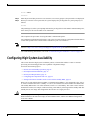
The RSP2 contains the central processing unit (CPU) and most of the memory components for the router.
The Cisco IOS software images reside in Flash memory, which is located on the RSP2:
Note
•
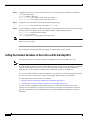
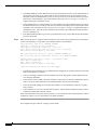
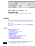
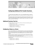
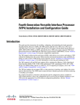
In the form of a single in-line memory module (SIMM) (U1 in Figure 2)
•
On up to two PC Cards (called Flash memory cards) that insert in the two PC Card slots (slot 0 and
slot 1) in the two PC Card slots (slot 0 and slot 1).
For specific Cisco IOS software release compatibility, refer to the “System Software” section on page 8
and to the Software Advisor at http://www.cisco.com/cgi-bin/Support/CompNav/Index.pl.
Storing the IOS software images in Flash memory enables you to download and boot from upgraded
Cisco IOS software images remotely or from software images resident in the RSP2 Flash memory,
without having to remove and replace read-only memory (ROM) devices.
The RSP2 also contains:
•
Most of the additional memory components used by the system, including 16-MB onboard Flash
memory and up to two Flash memory cards (16-MB, or 20-MB Flash memory card, with 20-MB
being the shipping default).
•
Air-temperature sensors for environmental monitoring. (All of the logic for the environmental
monitoring functions is contained on the router interface card.)
In addition to running the system software from DRAM, the RSP2 contains and executes the following
management functions that control the system:
OL-4923-01 B0
•
Sending and receiving routing protocol updates
•
Managing tables and caches
•
Monitoring interface and environmental status
3
Providing Simple Network Management Protocol (SNMP) management and the interface between
the console and Telnet
•
The high-speed switching section of the RSP2 communicates with and controls the interface processors
on the high-speed CyBus. This switching section decides the destination of a packet and switches it
based on that decision. The RSP2 uses a 16-million-instructions-per-second (mips) processor to provide
high-speed, autonomous switching and routing.
The RSP2 installs in the following slots on your Cisco 7000 or Cisco 7500 series router:
•
Slot 4 in the Cisco 7505 router
•
Slots 2 and 3 in the Cisco 7507 router
•
Slots 6 and 7 in the Cisco 7513 router
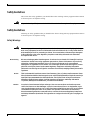
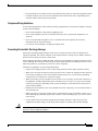
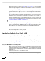
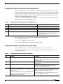
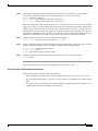
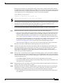
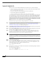
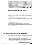
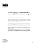
RSP2 (Front-Panel View)
T
AL
R
ES
ET
H
PU
C
LE
X
C
O
N
SO
AU
O
N
H7189
AS
E/M
SL
AV
ST
A
AN CTI
D VE
BY
ROUTE SWITCH PROCESSOR 4
R
M
SL
AL
S
O LO
T
T
1
0
TE
R
Figure 1
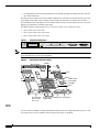
Note
A bank of hardware (Media Access Control [MAC]-layer) addresses for the interface ports is contained
in an NVRAM device on the router backplane.
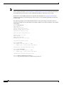
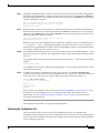
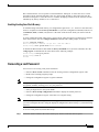
Figure 2
Route Switch Processor (RSP2)
Bus connector
SIMMs
CPU
U33
MD
AM
U21
U12
U4
H3105
U1
Bank 0
ROM monitor
(boot ROM)
NVRAM
U18
Bank 1
U30
PC Card slots
slot 0: bottom
slot 1: top
Flash memory Auxiliary port Console port
SIMM holder
CPU
The CPU used in the RSP2 is a Mips R4600 Reduced Instruction Set Computing (RISC) processor with
an external clock speed of 50 MHz, and an internal clock speed of 100 MHz.
4
OL-4923-01 B0
Memory Components
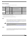
Table 1 shows the memory components on the RSP2.
Table 1
RSP2 Memory Components
Type
Size/Speed
Quantity
Description
DRAM
32-MB1 to 128-MB
SIMMs
1 to 4
32-, or 64-MB SIMMs (based on DRAM required) Bank 0: U21 and U33
for main Cisco IOS image functions
Bank 1: U12 and U4
NVRAM
128 KB
1
Nonvolatile SRAM for the system configuration
file2
U18
1
Contains the Cisco IOS images on the RSP2
U1
16-, or 20-, or Flash
memory card3
Up to 2
Contains the Cisco IOS images on up to two Flash Slot 0 and slot 1
memory cards4
256 KB
1
Flash EPROM for the ROM monitor program
image6
Flash memory 8-MB SIMM
Flash boot
ROM5
Location (see Figure 2)
U30
1. 32 MB of DRAM is the default DRAM configuration for the RSP2.
2. A system configuration file is contained in NVRAM, which allows the Cisco IOS software to control several system variables.
3. Only Intel Series 2 Flash memory cards can be used with the RSP2.
4. Type I, Type II, and Type III PC Cards can be used in PC Card slot 1, and Type I and Type II PC Cards can be used in slot 0.
5. The HSA feature requires boot ROM Version 11.1(2) or a later release of 11.1.
6. Downloading ROM monitor images to the Flash boot ROM device is not supported.
DRAM
DRAM stores routing tables, protocols, and network accounting applications and runs the Cisco IOS
software. The standard (default) RSP2 configuration is 32 MB of DRAM, with up to 128 MB available
through SIMM upgrades. DRAM is contained in up to four SIMM sockets: U21 and U33 (also called
bank 0) and U12 and U4 (also called bank 1). When upgrading DRAM, you must use SIMMs from Cisco.
(Also see the “Compatibility Requirements” section on page 12.)
Caution
To prevent memory problems, DRAM SIMMS must be 3.3-volt (V) devices. Do not attempt to install
higher-voltage devices in the RSP2 SIMM sockets.
For RSP2 DRAM upgrade procedures, refer to the “Replacing and Upgrading DRAM SIMMs” section
on page 71.
NVRAM
The system configuration, software configuration register settings, and environmental monitoring logs
are contained in the 128-KB NVRAM, which is backed up with built-in lithium batteries that retain the
contents for a minimum of 5 years. When replacing an RSP2, be sure to back up your configuration to a
remote server so you can retrieve it later.
OL-4923-01 B0
5
Caution
Before you replace an RSP2 in a system with one RSP2, back up the running configuration to a TFTP
file server or to Flash memory so you can retrieve it later. If the configuration is not saved, the entire
configuration will be lost—inside the NVRAM on the removed RSP2—and you will have to reenter the
entire configuration manually. For instructions on how to save the configuration file, see the “Saving and
Retrieving the Configuration File” section on page 66. This procedure is not necessary if you are
temporarily removing an RSP2; lithium batteries retain the configuration in memory until you replace
the RSP2 in the system.
Flash Memory
The Flash memory card for the RSP2 is an 16- or 20- Flash memory card, which conforms with the PC
Card normally Personal Computer Memory Card International Association (PCMCIA) format.
Both the onboard 8-MB and the 16- or 20-MB Flash memory card (PCMCIA cards) allow you to
remotely load and store multiple Cisco IOS software and microcode images. You can download a new
image over the network or from a local server and then add the new image to Flash memory or replace
the existing files. You can then boot routers either manually or automatically from any of the stored
images. Flash memory also functions as a TFTP server to allow other servers to boot remotely from
stored images or to copy them into their own Flash memory.
Caution
To prevent system problems, use Flash memory cards in the RSP2 that were formatted on an RP, RSP1,
or RSP7000 running Cisco IOS Release 11.1(8)CA1 or a later release of 11.1 CA1. You cannot use Flash
memory cards on the RSP2 (as storage or boot devices) that were formatted on an RP, RSP1, or RSP7000
using a Cisco IOS boot image earlier than Cisco IOS Release 11.1(8)CA1.
For a list of compatible software releases for the Flash memory card and Flash Disk, refer to the software
advisor at http://www.cisco.com/cgi-bin/Support/CompNav/Index.pl.
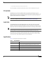
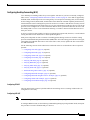
LEDs
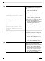
Table 2 describes the operation of the LEDs found on the RSP2:
Table 2
RSP2 LEDs
LED Label
Color
State
Indication
Green
On
RSP is on and receiving +5V.
Unlite
Off
No voltage through the board
Yellow
Yellow
RSP2 did not come out of reset; indicates hardware
problem with voltage level or PLL phase lock
Unlite
Off
RSP is operating normally.
Green
On
RSP is an active (HSA/HA configuration required).
Slave
Green
On
RSP is a standby RSP (HSA/HA configuration required).
Slot 0 PC Card
Green
On
PC Card in this slot is being accessed.
Slot 1 PC Card
Green
On
PC Card in this slot is being accessed.
Normal
1
CPU halt
Master
1
2
1. The RSP2 controls these LEDs and turns them on in parallel to indicate that the system is operational.
6
OL-4923-01 B0
2. If both the Master and Slave LEDs are unlite, the board is inactive.
The Active/Standby switch has been deactivated in software. The reset button boots the system.
PC Card Slots
The RSP2 has two PC Card slots available. Either slot can support a Flash memory card or an
input/output (I/O) device. Type I and Type II PC Cards can be used in PC Card slot 0 and slot 1. Type
III PC Cards can be used in slot 1. Not all Flash memory cards that are commercially available are
supported, and not all I/O devices are supported.
Note
Other Flash memory card limitations might apply. For additional Flash memory information, refer to the
Flash memory configuration notes listed in the “Related Documentation” section on page 2.
Serial Ports
Two asynchronous serial ports on the RSP2, labeled Console and Auxiliary, allow you to connect
external terminal devices to monitor and manage the system. The console port is an Electronics
Industries Association/Telecommunications Industry Association (EIA/TIA)-232 receptacle (female)
that provides a data circuit-terminating equipment (DCE) interface for connecting a console terminal.
Note
EIA/TIA-232 was known as recommended standard RS-232 before its acceptance as a standard by the
Electronic Industries Association (EIA) and Telecommunications Industry Association (TIA).
The auxiliary port is an EIA/TIA-232 plug (male) that provides a data terminal equipment (DTE)
interface; the auxiliary port supports flow control and is often used to connect a modem, a channel
service unit (CSU), or other optional equipment for Telnet management.
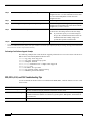
Specifications
Table 3 lists the physical specifications for the RSP2:
Table 3
OL-4923-01 B0
RSP Specifications
Description
Specifications
Physical dimensions
The RSP2 occupies one RSP slot and can only be operated in a
Cisco 7500 series or RSP7000-equipped Cisco 7000 series router.
Shipping weight
5 lb (2.25 kg)
Operating temperature
32 to 104˚F (0 to 40˚C)
Relative humidity
10 to 90 percent, noncondensing
Storage temperature
–4 to 149˚F (–20 to 65˚C)
7
System Software
The Cisco 7505, Cisco 7507, and Cisco 7513 routers support downloadable system software and
microcode for most Cisco IOS software and microcode upgrades. This enables you to remotely
download, store, and boot from a new image. The publication Upgrading Software and Microcode in
Cisco 7000 Series and Cisco 7500 Series Routers (DOC- 781144=) provides instructions for upgrading
over the network or from floppy disks.
Flash memory contains the default system software. An erasable programmable read-only memory
(EPROM) device contains the latest microcode version, in compressed form, for each interface
processor.
At system startup, an internal system utility scans for compatibility problems between the installed
interface processor types and the bundled microcode images. The utility then decompresses the images
into running dynamic random-access memory (DRAM). The bundled microcode images then function
the same as the EPROM images.
The Cisco IOS software images reside in Flash memory, which is located on the RSP2 in the form of a
single in-line memory module (SIMM), on Flash memory cards that insert in the two PC Card slots
(slot 0 and slot 1) on the front of the RSP2. (See Figure 2.) Storing the Cisco IOS images in Flash
memory enables you to download and boot from upgraded Cisco IOS images remotely or from software
images resident in the RSP2 Flash memory.
Although no monitoring of voltage or temperature is done by the RSP2, a comparator device ensures that
voltage is within the normal operating ranges, and three temperature sensors on the RSP2 send
temperature information to the chassis interface (CI) card. The CI card reports all voltage and
temperature readings, and these readings are available through standard software commands for
environmental monitoring. The RSP2 uses a software-controlled configuration register, so you do not
have to remove the RSP2 to configure jumpers. There are no user-configurable jumpers on the RSP2.
Note
The exception to this is CIP microcode, which, as of Cisco IOS Release 11.1(1), is unbundled from the
Cisco IOS software image bundle, and is available in a separate bundle on floppy disks, a TFTP server,
Cisco.com, or PC Card-based Flash memory media.
For the latest software release information, refer to the hardware/software compatibility matrix at
http://www.cisco.com/cgi-bin/front.x/Support/HWSWmatrix/hwswmatrix.cgi.
Installation Prerequisites
Before beginning the installation procedures, review the following sections to ensure awareness of the
appropriate regulatory and safety requirements, and to ensure that your RSP2 hardware functions
properly with compatible components:
Note
8
•
Safety Guidelines, page 9
•
Compatibility Requirements, page 12
If you are replacing an existing RSP2, back up your current configuration file to a remote server before
you remove the RSP2 to avoid having to reenter all your current configuration information manually. To
back up the file, you need access to a remote server. For instructions for uploading the file and retrieving
it after the new RSP2 is installed, see the “Saving and Retrieving the Configuration File” section on
page 66.
OL-4923-01 B0
Safety Guidelines
This section lists safety guidelines you should follow when working with any equipment that connects
to electrical power or telephone wiring.
Warning
Only trained and qualified personnel should be allowed to install or replace this equipment.
Safety Guidelines
Following are safety guidelines that you should follow when working with any equipment that connects
to electrical power or telephone wiring.
Safety Warnings
Warning
This warning symbol means danger. You are in a situation that could cause bodily injury. Before you
work on any equipment, be aware of the hazards involved with electrical circuitry and be familiar
with standard practices for preventing accidents. To see translations of the warnings that appear
in this publication, refer to the Regulatory Compliance and Safety Information document that
accompanied this device.
Waarschuwing
Dit waarschuwingssymbool betekent gevaar. U verkeert in een situatie die lichamelijk letsel kan
veroorzaken. Voordat u aan enige apparatuur gaat werken, dient u zich bewust te zijn van de bij
elektrische schakelingen betrokken risico's en dient u op de hoogte te zijn van standaard
maatregelen om ongelukken te voorkomen. Voor vertalingen van de waarschuwingen die in deze
publicatie verschijnen, kunt u het document Regulatory Compliance and Safety Information
(Informatie over naleving van veiligheids- en andere voorschriften) raadplegen dat bij dit toestel is
ingesloten.
Varoitus
Tämä varoitusmerkki merkitsee vaaraa. Olet tilanteessa, joka voi johtaa ruumiinvammaan. Ennen
kuin työskentelet minkään laitteiston parissa, ota selvää sähkökytkentöihin liittyvistä vaaroista ja
tavanomaisista onnettomuuksien ehkäisykeinoista. Tässä julkaisussa esiintyvien varoitusten
käännökset löydät laitteen mukana olevasta Regulatory Compliance and Safety Information
-kirjasesta (määräysten noudattaminen ja tietoa turvallisuudesta).
Attention
Ce symbole d'avertissement indique un danger. Vous vous trouvez dans une situation pouvant
causer des blessures ou des dommages corporels. Avant de travailler sur un équipement, soyez
conscient des dangers posés par les circuits électriques et familiarisez-vous avec les procédures
couramment utilisées pour éviter les accidents. Pour prendre connaissance des traductions
d’avertissements figurant dans cette publication, consultez le document Regulatory Compliance
and Safety Information (Conformité aux règlements et consignes de sécurité) qui accompagne cet
appareil.
OL-4923-01 B0
9
Warnung
Avvertenza
Advarsel
Aviso
Dieses Warnsymbol bedeutet Gefahr. Sie befinden sich in einer Situation, die zu einer
Körperverletzung führen könnte. Bevor Sie mit der Arbeit an irgendeinem Gerät beginnen, seien Sie
sich der mit elektrischen Stromkreisen verbundenen Gefahren und der Standardpraktiken zur
Vermeidung von Unfällen bewußt. Übersetzungen der in dieser Veröffentlichung enthaltenen
Warnhinweise finden Sie im Dokument Regulatory Compliance and Safety Information
(Informationen zu behördlichen Vorschriften und Sicherheit), das zusammen mit diesem Gerät
geliefert wurde.
Questo simbolo di avvertenza indica un pericolo. La situazione potrebbe causare infortuni alle
persone. Prima di lavorare su qualsiasi apparecchiatura, occorre conoscere i pericoli relativi ai
circuiti elettrici ed essere al corrente delle pratiche standard per la prevenzione di incidenti. La
traduzione delle avvertenze riportate in questa pubblicazione si trova nel documento Regulatory
Compliance and Safety Information (Conformità alle norme e informazioni sulla sicurezza) che
accompagna questo dispositivo.
Dette varselsymbolet betyr fare. Du befinner deg i en situasjon som kan føre til personskade. Før du
utfører arbeid på utstyr, må du vare oppmerksom på de faremomentene som elektriske kretser
innebærer, samt gjøre deg kjent med vanlig praksis når det gjelder å unngå ulykker. Hvis du vil se
oversettelser av de advarslene som finnes i denne publikasjonen, kan du se i dokumentet
Regulatory Compliance and Safety Information (Overholdelse av forskrifter og
sikkerhetsinformasjon) som ble levert med denne enheten.
Este símbolo de aviso indica perigo. Encontra-se numa situação que lhe poderá causar danos
físicos. Antes de começar a trabalhar com qualquer equipamento, familiarize-se com os perigos
relacionados com circuitos eléctricos, e com quaisquer práticas comuns que possam prevenir
possíveis acidentes. Para ver as traduções dos avisos que constam desta publicação, consulte o
documento Regulatory Compliance and Safety Information (Informação de Segurança e
Disposições Reguladoras) que acompanha este dispositivo.
¡Advertencia!
Este símbolo de aviso significa peligro. Existe riesgo para su integridad física. Antes de manipular
cualquier equipo, considerar los riesgos que entraña la corriente eléctrica y familiarizarse con los
procedimientos estándar de prevención de accidentes. Para ver una traducción de las
advertencias que aparecen en esta publicación, consultar el documento titulado Regulatory
Compliance and Safety Information (Información sobre seguridad y conformidad con las
disposiciones reglamentarias) que se acompaña con este dispositivo.
Varning!
Denna varningssymbol signalerar fara. Du befinner dig i en situation som kan leda till personskada.
Innan du utför arbete på någon utrustning måste du vara medveten om farorna med elkretsar och
känna till vanligt förfarande för att förebygga skador. Se förklaringar av de varningar som
förkommer i denna publikation i dokumentet Regulatory Compliance and Safety Information
(Efterrättelse av föreskrifter och säkerhetsinformation), vilket medföljer denna anordning.
Electrical Equipment Guidelines
Follow these basic guidelines when working with any electrical equipment:
10
•
Before beginning any procedures requiring access to the chassis interior, locate the emergency
power-off switch for the room in which you are working.
•
Disconnect all power and external cables before moving a chassis.
•
Do not work alone when potentially hazardous conditions exist.
•
Never assume that power has been disconnected from a circuit; always check.
OL-4923-01 B0
•
Do not perform any action that creates a potential hazard to people or makes the equipment unsafe.
•
Carefully examine your work area for possible hazards such as moist floors, ungrounded power
extension cables, and missing safety grounds.
Telephone Wiring Guidelines
Use the following guidelines when working with any equipment that is connected to telephone wiring or
to other network cabling:
•
Never install telephone wiring during a lightning storm.
•
Never install telephone jacks in wet locations unless the jack is specifically designed for wet
locations.
•
Never touch uninsulated telephone wires or terminals unless the telephone line has been
disconnected at the network interface.
•
Use caution when installing or modifying telephone lines.
Preventing Electrostatic Discharge Damage
Electrostatic Discharge (ESD) damage, which can occur when electronic cards or components are
improperly handled, can result in complete or intermittent failures. Each processor module contains a
printed circuit card that is fixed in a metal carrier.
Electromagnetic interference (EMI) shielding, connectors, and a handle are integral components of the
carrier. Although the metal carrier helps to protect the board from ESD, use an ESD-preventive wrist or
ankle strap whenever you handle any electronic system component.
Following are guidelines for preventing ESD damage:
Caution
OL-4923-01 B0
•
Always use an ESD-preventive wrist or ankle strap and ensure that it makes good skin contact.
•
When you work at the interface processor end of the router, connect the equipment end of the strap
to the captive installation screw on an installed interface processor, or to the chassis grounding
receptacle that is located next to each power supply.
•
When you install a processor module, use the ejector levers to properly seat the bus connectors in
the backplane, and then tighten both captive installation screws. These screws prevent accidental
removal, provide proper grounding for the system, and help to ensure that the bus connectors are
seated in the backplane.
•
Handle processor modules by the carrier handles and carrier edges only; never touch the board or
any connector pins.
•
When you remove a processor module, place it component side up on an antistatic surface or in a
static shielding bag. Immediately place the module in a static shielding bag if you need to return it
to the factory.
•
Avoid contact between electronic equipment and clothing. Antistatic straps only protect the
equipment from ESD voltages on the body; ESD voltages on clothing can still cause damage.
For safety, periodically check the resistance value of the antistatic strap. The measurement should be
between 1 and 10 megohms (Mohms).
11
Compatibility Requirements
This section describes important compatibility requirements for the RSP2.
Chassis Slot and DRAM Requirements
Following are chassis slot and DRAM requirements for ensuring RSP2 compatibility.
•
You have no restrictions on installing an RSP2 in a Cisco 7505. However, the Cisco 7505 does not
support the HSA or the HA features.
•
You have no restrictions on installing an RSP2 in a Cisco 7507 provided that you install the RSP2
in slot 2 or slot 3, or both. With the HSA or HA features enabled, you will install an RSP2 (or an
RSP4/4+ and an RSP2) in both RSP slots.
•
You have no restrictions on installing an RSP2 in a Cisco 7513 provided that you install the RSP2
in slot 6 or slot 7, or both. With the HSA or HA features enabled, you will install an RSP2 (or an
RSP4/4+ and an RSP2) in both RSP slots.
•
It is assumed that if you install two RSP2s (or am RSP4/4+ and an RSP2) in the Cisco 7507 or
Cisco 7513, you plan to enable and configure the HSA or HA features.
Memory Requirements
Flash memory cards and DRAM SIMMs must meet the following requirements:
•
Flash memory cards and DRAM SIMMs must be obtained from Cisco Systems. Flash memory cards
are available in 16 MB or 20 MB, with 16 MB being the shipping default. See the “PC Card Slots”
section on page 7 for additional information on supported Flash memory cards.
•
Maximum DRAM speed is 60 nanoseconds (ns), maximum SIMM height is 1 inch
(2.54 centimeters), and maximum DRAM SIMM voltage is 3.3 volts (V).
•
The minimum required DRAM configuration for the RSP2 is 32MB.
•
Flash memory cards and DRAM SIMMs must be obtained from Cisco Systems. See the “PC Card
Slots” section on page 7 for additional information on supported PC Cards.
•
You cannot use a Flash memory card that was formatted on another RSP-based system, such as the
RSP7000, or RSP1 which is running a boot or Cisco IOS software image earlier than 10.3(6) or a
later release of Cisco IOS release 10.3.
•
You must first reformat the Flash memory card, formatted on one of these other RSP-based systems,
before you can use it as a boot or storage source with the RSP2. Refer to Flash Memory Card
Installation Instructions (part number DOC-782083=) for instructions on reformatting a Flash
memory card.
•
The HSA and HA features require that the boot read-only memory (ROM) device (U30, shown in
the “System Software” section on page 8) be updated to Version 11.1(2) or a later release of 11.1.
To check the boot ROM (also called the system bootstrap) version currently running on your RSP2,
use the show version command and check the boot ROM version number as follows:
Router# show version
(display text omitted)
System Bootstrap, Version 11.1(2)
12
OL-4923-01 B0
Software Prerequisites
The minimum supported Cisco IOS release compatible with the RSP2 is 10.3(6) or a later release of
Cisco IOS release 10.3. For the latest compatible software releases, refer to the software advisor at
http://www.cisco.com/cgi-bin/Support/CompNav/Index.pl.
Note
The 32-MB Flash memory card is compatible with Cisco IOS Release 12.1(5)T1 or a later release of
Cisco IOS Release 12.1 T.
Use the show version and show hardware commands to display the router’s current hardware and
software configurations. The show microcode command lists the bundled microcode (and target
hardware) version for each processor type. The show controller cbus command shows the microcode
version you are running. The show diagbus command shows the RSP2 board’s hardware version and
revision.
For additional descriptions of show commands, refer to the Configuration Fundamentals Configuration
Guide and Configuration Fundamentals Command Reference publications, which are available online,
on the Documentation CD-ROM, or as printed documents.
Note
If the required system software and microcode are not available in your system, contact a customer
service representative for upgrade information. (To obtain assistance, see the “Obtaining Technical
Assistance” section on page 86.)
Hardware Prerequisites
Your router configuration, protocols and features might require more than the 32 MB of DRAM that is
shipped with the RSP2. To upgrade DRAM, see the “Software Configuration Register Settings” section
on page 79.
To ensure proper operation of a system configured for HSA or HA, note the guidelines below:
Caution
•
With HSA and HA, the RSP2 can interoperate with another RSP2, with an RSP4, or with an RSP4+.
•
To ensure that the standby RSP2 operates properly, the active and the standby RSP2 (or the RSP2
and the RSP4/4+) should have the same DRAM configuration and boot ROM version.
•
Removing the active RSP2 while the system is operating might cause the system to crash; however,
the system reloads with the standby RSP2 as the new active RSP2. To prevent system problems, do
not remove the active RSP2 while the system is operating.
Before using a Flash memory card previously formatted and used in an RSP, RSP7000, or RSP1, you
must reformat the Flash memory card. Flash memory cards formatted on any of these processors do not
work properly in an RSP2. You must first reformat it on your RSP2 system. Refer to Flash Memory Card
Installation Instructions (part number DOC-782083=) for instructions on reformatting Flash memory.
Microcode Requirements
Microcode is a set of processor-specific software instructions that enables and manages the features and
functions of a specific processor type. At system startup or reload, the system loads the microcode for
each processor type present in the system. The latest available microcode image for each processor type
is bundled and distributed with the system software image.
OL-4923-01 B0
13
Note
Overriding the bundle can result in incompatibility among the various interface processors in the system.
We recommend that you use only the microcode image that is bundled. The exception to this is CIP
microcode, which as of Cisco IOS Release 11.1(1), is unbundled from the IOS software image bundle,
and is available in a separate bundle on floppy disks, a TFTP server, CCO, or Flash memory cards.
Installing the RSP2
The following sections describe the procedures for installing or replacing an RSP2. Ensure that your
system meets the minimum software, hardware, and microcode requirements described in the following:
“Software Prerequisites” section on page 13, “Hardware Prerequisites” section on page 13, and
“Microcode Requirements” section on page 13. Proceed to the “Removing the RSP2” section on page 15
for instructions on removing the RSP2, and then to the “Replacing the RSP2” section on page 17 for
installation instructions. After the new RSP2 is secure, follow the procedures in the “Troubleshooting
the Installation” section on page 60 to verify that it is installed and functioning properly.
Caution
Removing the only installed RSP2 from a system while the system is operating will cause the system to
crash. Consider this before removing an RSP2 while the system is operating. To ensure that the standby
RSP2 operates properly with the full system configuration should the active RSP2 ever fail, the standby
RSP2 must have the same DRAM and the same (or higher) Flash memory capacity as the active RSP2.
See the “Memory Components” section on page 5 for RSP2 memory component requirements.
Note
The carriers on processor modules have EMI fences for EMI shielding; therefore, they fit very tightly in
the chassis slots. To ensure that you can properly remove or install an RSP2 in RSP slot 7 from the
Cisco 7513 router, we recommend that you proceed as follows: first remove an interface processor
installed in slot 8, remove or install the RSP2 in RSP slot 7 (and fasten its captive installation screws as
appropriate), and then reinstall the interface processor in slot 8.
List of Parts and Tools
You need some or all of the following parts and tools to remove and replace an RSP2 or to upgrade
DRAM. If you need additional equipment, contact a customer service representative for ordering
information.
Caution
•
An RSP2 or related product listed in the “Connecting the Console Terminal” section on page 18.
•
DRAM SIMMs from Cisco if you are replacing SIMM, as described in the “Replacing and
Upgrading DRAM SIMMs” section on page 71. (Also see the “Compatibility Requirements” section
on page 12.)
To prevent memory problems, DRAM SIMMs must be 3.3-volt (V) devices. Do not attempt to install
higher-voltage devices in the RSP2 SIMM sockets.
•
14
Number 2 Phillips or 3/16-inch flat-blade screwdriver for the captive installation screws that secure
the RSP2 in its slot.
OL-4923-01 B0
•
ESD-prevention equipment or the disposable ESD-preventive wrist strap included with all spares
and upgrade kits.
•
Antistatic mat, foam pad, or bag for the removed RSP2 (place the removed RSP2 into an antistatic
bag if you plan to return it to the factory, or on an antistatic mat or foam if you are replacing
components and will reinstall the RSP2).
•
DRAM SIMMs from Cisco if you are replacing SIMMs.
Removing the RSP2
When you remove or install the RSP2, be sure to use the ejector levers, which help to ensure that the
RSP2 is fully inserted in the backplane or fully dislodged from it. An RSP2 that is only partially
connected to the backplane can halt the system unless a second RSP2 is installed.
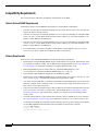
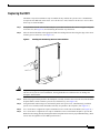
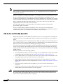
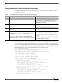
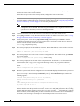
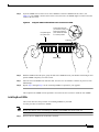
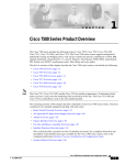
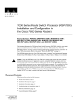
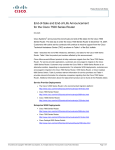
Figure 3 shows a detail of the ejector lever mechanism that is appropriate for the router. When you
simultaneously push the ejector levers inward (toward the carrier handle), the levers push the RSP2 into
the slot and ensure that the board connectors are fully seated in the backplane. Follow these steps to
remove the RSP2:
Step 1
Optional step: If you are replacing the RSP2 in a system with one RSP2, copy the currently running
configuration file to a TFTP server so you can retrieve it later. (See the “Saving and Retrieving the
Configuration File” section on page 66.)
Step 2
Attach an antistatic strap to yourself and then connect the equipment end of the strap to a captive
installation screw on an installed interface processor, or to any unfinished chassis surface.
Step 3
If you are replacing the RSP2, disconnect any devices that are attached to the console or auxiliary ports.
If you are removing the RSP2 for maintenance and will reinstall the same one, you can leave the devices
attached provided that doing so will not strain the cables.
Step 4
Use a screwdriver to loosen the two captive installation screws. (See Figure 3.)
Step 5
Place your thumbs on the ends of each of the ejectors and simultaneously pull them both outward, away
from the carrier handle (in the opposite direction from that shown in Figure 3c) to release the carrier
from the slot and to dislodge the RSP2 from the backplane.
Step 6
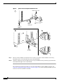
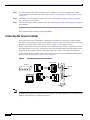
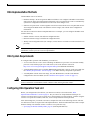
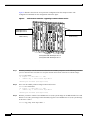
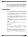
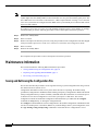
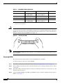
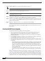
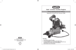
Grasp the handle of the RSP2 with one hand and pull the RSP2 straight out of the slot, keeping your
other hand under the carrier to guide it. (See Figure 4.) Keep the carrier parallel to the backplane. Avoid
touching the board or any connector pins.
OL-4923-01 B0
15
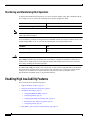
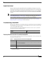
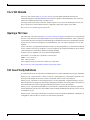
Figure 3
Ejector Levers and Captive Installation Screw
Bottom ejector lever
a
Processor
module
carrier guide
Processor module
slot
Captive
installation
screw
c
b
H1482a
STOP!
on contact
Step 7
Place the removed RSP2 on an antistatic mat or foam. If you plan to return the RSP2 to the factory,
immediately place it in an antistatic bag to prevent ESD damage.
Step 8
Attach the equipment end of the ESD-preventive strap to the RSP2 before performing any maintenance
on the RSP2 that might create an ESD hazard.
This completes the removal procedure. If you removed the RSP2 to replace SIMMs, proceed to the
“Software Configuration Register Settings” section on page 79. If you are replacing the RSP2, proceed
to the next section to install the new RSP2.
16
OL-4923-01 B0
Replacing the RSP2
The RSP2 is keyed for installation only in an RSP slot. By default, the system active is the RSP that
occupies the first RSP slot in the router: slot 2 in the Cisco 7507, and slot 6 in the Cisco 7513. Follow
these steps to install an RSP2:
Step 1
Grasp the RSP2 handle with one hand and place your other hand under the carrier to support and guide
it into the slot. (See Figure 4.) Avoid touching the board or any connectors.
Step 2
Place the back of the RSP2 in the appropriate RSP slot and align the notches along the edge of the carrier
with the grooves in the slot. (See Figure 3a.)
Handling the RSP2 During Removal and Installation
H1355a
Figure 4
Caution
To prevent damage to the backplane, you must install the RSP2 in one of the two RSP slots on the router.
The slots are keyed for correct installation. Forcing the RSP2 into a different slot can damage the
backplane and the RSP2.
Step 3
While keeping the RSP2 parallel to the backplane, carefully slide the carrier into the slot until the RSP2
faceplate makes contact with the ejector levers, and then stop. (See Figure 3b.)
Step 4
Using the thumb and forefinger of each hand to pinch each ejector lever, simultaneously push both
ejector levers inward (toward the handle) until they are parallel to the faceplate. (See Figure 3c.)
Step 5
Use a screwdriver to tighten the captive installation screws on the ends of the RSP2. (See Figure 3a.)
Step 6
Use a screwdriver to tighten the two captive installation screws on the RSP2 faceplate to prevent the
RSP2 from becoming partially dislodged from the backplane and to ensure proper EMI shielding. (These
screws must be tightened to meet EMI specifications.)
OL-4923-01 B0
17
Step 7
If you disconnected the console terminal to remove the RSP2, or if you are installing a new RSP2,
connect the console terminal to the console port. (See the “Connecting the Console Terminal” section
on page 18.)
Step 8
Ensure that a console terminal is connected (see the “Connecting the Console Terminal” section on
page 18) and that it is turned on.
Step 9
Turn the system power back on, and proceed to the “Restarting the System” section on page 20 to check
the installation.
This completes the procedure for replacing the RSP2.
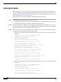
Connecting the Console Terminal
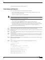
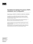
The system console port on the RSP2 is a DCE DB-25 receptacle for connecting a console terminal,
which you need to configure in order to communicate with your system. The console port is located on
the RSP2 to the right of the auxiliary port, as shown in Figure 5, and is labeled Console.
Before connecting the console port, check the documentation for your terminal to determine the baud
rate of the terminal you are using. The baud rate of the terminal must match the default baud rate (9600
baud). Set up the terminal as follows: 9600 baud, 8 data bits, no parity, and 2 stop bits (9600,8N2).
Use the console cable provided to connect the terminal to the console port on the RSP2, and then follow
the steps in the “Restarting the System” section on page 20.
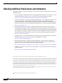
Figure 5
Console and Auxiliary Port Connections
DB-25 female
Modem
Auxiliary
port
Console
port
DB-25 male
RSP
Note
18
H3538
Console terminal
The console and auxiliary ports are asynchronous serial ports; any devices connected to these ports must
be capable of asynchronous transmission. (Asynchronous is the most common type of serial device; for
example, most modems are asynchronous devices.)
OL-4923-01 B0
Connecting to the Auxiliary Port
The auxiliary port on the RSP2 is a DB-25 plug DTE port for connecting a modem or other DCE device
(such as a channel service unit [CSU], data service unit [DSU], or other router) to the router. The port is
located above the console port on the RSP2 and is labeled AUX. An example of a modem connection is
shown in Figure 5.
Using the Y-Cables for Console and Auxiliary Connections
For systems with two RSP2s installed and the HSA or HA feature enabled, you can connect to either the
console or auxiliary ports simultaneously on both RSPs using a special, optional Y-cable. If only one
RSP2 is installed, it is the system active by default.
Note
The Y-cables are not required; two individual console cables and two individual auxiliary cables can be
used instead.
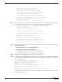
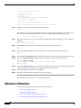
Figure 6 shows the console Y-cable and Figure 7 shows the auxiliary Y-cable.
Figure 6
Console Y-Cable (Part Number CAB-RSP2CON=)
CONSOLE
DB-25 female
DB-25 male
Console connectors
to console ports on two
RSP2s in RSP slots 2 and 3
To console terminal
CONSOLE
AUXILIARY
DB-25 male
DB-25 female
Auxiliary connectors
to auxiliary ports on two
RSP2s in RSP slots 2 and 3
To external
auxiliary equipment
AUXILIARY
OL-4923-01 B0
H3181
Auxiliary Y-Cable (Part Number CAB-RSP2AUX=)
DB-25 female
H3182
Figure 7
DB-25 male
19
Restarting the System
When you turn the system power back on, verify that the system boots and resumes normal operation. If
you are restarting the system after upgrading the DRAM, expect that it will take the system longer to
complete the memory initialization portion of the boot sequence with more DRAM. (See the “Verifying
System Startup Sequence” section on page 62.)
Follow these steps to verify that the RSP2 is installed and functioning properly:
Step 1
Check the RSP2 connections to make sure they are secure:
•
The RSP2 is inserted all the way into its slot, and both the captive installation screws are tightened.
•
The console terminal is turned on and is connected to the console port.
Step 2
Observe the RSP2 LEDs. While the system initializes, the CPU halt LED on the RSP2 stays on. It goes
off when the boot process is complete. As the RSP2 initializes each interface processor, the status LEDs
on each interface processor go on and off in irregular sequence.
Step 3
For a Cisco 7507 or Cisco 7513 with HSA or HA configured, verify that the console terminal displays
the system banner and startup screen as the system restarts.
•
The active console display should look similar to the following for a Cisco 7513 (note the RSP2 slots
indicated):
System Bootstrap, Version 11.1(2), RELEASED SOFTWARE
Copyright (c) 1986-1996 by cisco Systems, Inc.
SLOT 6 RSP2 is system master
SLOT 7 RSP2 is system slave
RSP2 processor with 16384 Kbytes of main memory
[additional displayed text omitted from this example]
Cisco Internetwork Operating System Software
IOS (tm) GS Software (RSP-JV), Version 11.1(4) [biff 51096]
Copyright (c) 1986-1996 by cisco Systems, Inc.
Compiled Mon 22-Jan-96 21:15 by biff
Image text-base: 0x600108A0, data-base: 0x607B8000
cisco RSP2 (R4600) processor with 16384K bytes of memory.
R4600 processor, Implementation 32, Revision 2.0
[additional displayed text omitted from this example]
8192K bytes of Flash PCMCIA card at slot 0 (Sector size 128K).
8192K bytes of Flash internal SIMM (Sector size 256K).
Slave in slot 7 is halted.
[additional displayed text omitted from this example]
•
The active console display should look similar to the following for a Cisco 7507 (note the RSP2 slots
indicated):
System Bootstrap, Version 11.1(2), RELEASED SOFTWARE
Copyright (c) 1986-1996 by cisco Systems, Inc.
SLOT 2 RSP2 is system master
SLOT 3 RSP2 is system slave
RSP2 processor with 16384 Kbytes of main memory
[additional displayed text omitted from this example]
Cisco Internetwork Operating System Software
IOS (tm) GS Software (RSP-JV), Version 11.1(4) [biff 51096]
20
OL-4923-01 B0
Copyright (c) 1986-1996 by cisco Systems, Inc.
Compiled Mon 22-Jan-96 21:15 by biff
Image text-base: 0x600108A0, data-base: 0x607B8000
cisco RSP2 (R4600) processor with 16384K bytes of memory.
R4600 processor, Implementation 32, Revision 2.0
[additional displayed text omitted from this example]
8192K bytes of Flash PCMCIA card at slot 0 (Sector size 128K).
8192K bytes of Flash internal SIMM (Sector size 256K).
Slave in slot 3 is halted.
[additional displayed text omitted from this example]
Step 4
With a single RSP2 (non-HSA or non-HA), verify that the console terminal displays the system banner
and startup screen as the system restarts. The display should look similar to the following:
System Bootstrap, Version 11.1(2) [biff 51096], RELEASED SOFTWARE
Copyright (c) 1994-1996 by cisco Systems, Inc.
SLOT 6 RSP2 is system master
RSP2 processor with 16384 Kbytes of main memory
[additional displayed text omitted from this example]
Cisco Internetwork Operating System Software
IOS (tm) GS Software (RSP-JV), Version 11.1(4) [biff 51096]
Copyright (c) 1986-1996 by cisco Systems, Inc.
Compiled Mon 22-Jan-96 21:15 by biff
Image text-base: 0x600108A0, data-base: 0x607B8000
cisco RSP2 (R4600) processor with 16384K bytes of memory.
R4600 processor, Implementation 32, Revision 2.0
[additional displayed text omitted from this example]
Step 5
After the system boots the software and initializes the interface processors, verify that the RSP2 LEDs
are in the following states:
•
RSP2 normal LED is on (for each RSP2 installed).
•
CPU halt LED is off (for each RSP2 installed).
•
Active RSP2 active LED is on (if HSA or HA is configured).
•
Standby RSP2 standby LED is on (if HSA or HA is configured).
Step 6
Verify that all the enabled LEDs (on the interface processors) are on.
Step 7
In systems with a second RSP2 installed (and HSA or HA configured), use the show version command
to verify that the standby RSP2 is recognized by the system. Following is a sample from a Cisco 7513:
Router> show version
Cisco Internetwork Operating System Software
IOS (tm) GS Software (RSP-JV), Version 11.1(4) [biff 51096]
Copyright (c) 1986-1996 by cisco Systems, Inc.
Compiled Mon 22-Jan-96 21:15 by biff
Image text-base: 0x600108A0, data-base: 0x607B8000
[additional displayed text omitted from this example]
Slave in slot 7 is running Cisco Internetwork Operating System Software
(Note that this could also be “slot 6” depending on which RSP2 is configured as the slave or the recent
crash history of your router.)
OL-4923-01 B0
21
When you have verified all the conditions in Step 2 through Step 6 (or Step 7 if you have a second RSP2
installed and want to use the HSA or the HA features), the installation is complete. If you replaced the
RSP2 and saved your configuration file to a remote server before doing so, see the “Retrieving the
Configuration File” section on page 69. If you replaced the RSP2 and did not save the configuration, use
the configure command or the setup command facility to reenter the configuration information.
An error condition exists if no LEDs go on at power up or after initialization, or if the CPU halt LED
goes on and remains on. If this happens, proceed to the “Troubleshooting the Installation” section on
page 60 to try to isolate the problem.
For more complete configuration information, refer to the Configuration Fundamentals Configuration
Guide and the Configuration Fundamentals Command Reference publications, which are available on
the Documentation CD-ROM or as printed documents.
If you have a second RSP2 installed, you must configure the HSA (or HA, if you prefer) features for your
Cisco 7507 or Cisco 7513 router. Read the following caution, and then proceed to the following section,
“Configuring High System Availability” section on page 23.
Caution
When you install a second RSP2 card for the first time and plan to enable the HSA or HA features, you
must immediately configure it correctly. See the “Configuring High System Availability” section on
page 23, or the “Enabling High Availability Features” section on page 38. This ensures that the new
standby is configured consistently with the active. Failure to do so may result in an unconfigured standby
RSP2 (or RSP4/4+) taking over the router when the active fails, rendering the network inoperable.
This completes the procedure for restarting the system.
Configuring the Router for a Single RSP2
If you have a single RSP2, you can configure your system according to the Cisco IOS release appropriate
for your router. See the Cisco IOS software configuration documentation set that corresponds to the
software release installed on your Cisco hardware at
http://www.cisco.com/univercd/cc/td/doc/product/software/index.htm.
If you have more than one RSP2 (or an RSP2 and an RSP4/4+), and you are using a Cisco 7507 router
or a Cisco 7513 router, you must configure your router for either high system availability (HSA) the
default, (see the “Configuring High System Availability” section on page 23), or high availability (HA),
(see the “Enabling High Availability Features” section on page 38).
Using the EXEC Command Interpreter
Before you configure your system using the EXEC-level commands, you must enter the privileged level
of the EXEC command interpreter using the enable command. The system prompts you for a password
if one has been set. The system prompt for the privileged level ends with a pound sign (#) instead of an
angle bracket (>).
At the console terminal, enter the privileged level as follows:
Step 1
22
At the EXEC prompt (>), enter the enable command. The EXEC command interpreter prompts you for
a privileged-level password, as follows:
OL-4923-01 B0
Router> enable
Password:
Step 2
Enter the password (the password is case sensitive). For security purposes, the password is not displayed.
Step 3
When you enter the correct password, the system displays the privileged-level system prompt (#) as
follows:
Router#
The pound sign (#) at the system prompt indicates the privileged level of the EXEC command interpreter,
from which you can execute EXEC-level commands.
This completes the procedure for using the EXEC command interpreter.
For configuration information and support, refer to the Cisco IOS software configuration documentation
set that corresponds to the software release installed on your Cisco hardware.
Note
You can access Cisco IOS software configuration at http://www.cisco.com. Refer to the Software
Advisor at http://www.cisco.com/cgi-bin/Support/CompNav/Index.pl for additional information.
For troubleshooting information, refer to the “Troubleshooting the Installation” section on page 60.
Configuring High System Availability
This section describes high system availability (HSA), a feature that enables a router to continue
processing and forwarding packets after a planned or unplanned outage.
It includes the following topics:
•
HSA Active and Standby Operation, page 24
•
HSA Implementation Methods, page 25
•
HSA System Requirements, page 25
•
Configuring HSA Operation Task List, page 25
•
Setting Environment Variables on the Active and the Standby RSPs, page 36
HSA is the system default when two RSP2s, or an RSP2 and an RSP4/4+ (one designated as the “active”
or “master” and the other as the “standby” or “slave”) are installed in a router and the active RSP2 fails.
The standby RSP2 takes over in this situation, known as a “cold standby.” The router restarts without
manual intervention (for example, without inserting a new RSP) by rebooting with the standby RSP. The
standby has its own image and configuration file and acts as a single processor.
Caution
OL-4923-01 B0
To ensure proper functioning of the standby RSP2 in the event of an active RSP2 failure, the standby
RSP2 should have the same boot image, the same ROM monitor, and the same DRAM configuration
as the active RSP2.
23
Note
An RSP2 can interoperate with another RSP2, or with an RSP4/4+. It cannot interoperate with an
RSP1, an RSP8, or an RSP16. In the following text, you can substitute references to two RSP2s with
an RSP2 and an RSP4/4+.
When two new RSP2s (or an RSP2 and an RSP4/4+) are installed at the same time, the RSP that occupies
the first even RSP slot on the router is the active (normally the RSP4/4+ if the RSP2 is used in
conjunction with the RSP4/4+), and the RSP that occupies the odd RSP slot is the standby. If a crash has
occurred, the RSP in the odd slot becomes the active and the RSP in the even slot becomes the standby.
HSA is supported with RSP2 on the following routers: Cisco 7507, and Cisco 7513. HSA is not
supported on the Cisco 7505 or the Cisco 7576 routers.
The cold standby procedure, from initial failure to first packet transmission, currently takes
approximately eight to ten minutes.
For more complete HSA configuration information, refer to the Configuration Fundamentals
Configuration Guide and the Configuration Fundamentals Command Reference publications, which are
available online, on the Cisco Documentation CD-ROM, or as printed copies.
HSA Active and Standby Operation
During HSA operation, the active RSP2 card functions as if it were a single processor, controlling all
functions of the router. The standby RSP2 card does nothing but actively monitor the active RSP2 for
failure.
When the standby RSP2 detects a nonfunctional active RSP2, the standby resets itself and takes part in
active-standby arbitration. Active-standby arbitration is a ROM monitor process that determines which
RSP2 card is the active and which is the standby upon startup (or reboot).
If a system crash causes the active RSP2 to fail, the standby RSP2 becomes the new active RSP2 and
uses its own system image and configuration file to reboot the router. The failed RSP2 card (now the
standby) remains inactive until you perform diagnostics, correct the problem, and then issue the standby
reload command.
With HSA operation, use the following guidelines:
Caution
24
•
The standby RSP2 should have the same boot image, the same ROM monitor, and the same DRAM
configuration as the active RSP2. (See the “Hardware Prerequisites” section on page 13.)
•
The two RSP2 cards are not required to run the same active software image and configuration file.
The standby-mode software is a subset of the active-mode software.
•
When enabled, automatic synchronization mode automatically ensures that the active and the
standby RSP2 cards have the same configuration file. (See the “Software Prerequisites” section on
page 13.)
•
The console always connects to the active RSP2, so your view is always from the active’s
perspective.
•
You must not remove the system active RSP2 while the system is operating; however, the system
standby RSP2 can be removed while the system is operating.
Removing the active RSP2 while the system is operating might cause the system to crash; however,
the system reloads with the standby RSP2 as the new active. To prevent any system problems, do not
remove the active RSP2 while the system is operating.
OL-4923-01 B0
HSA Implementation Methods
Common HSA uses are as follows:
•
Hardware backup—Protects against an RSP2 card failure. You configure both RSP2 cards with the
same software image and configuration information, and you configure the router to automatically
synchronize configuration information on both cards when changes occur.
•
Software error protection—Protects against critical Cisco IOS software errors in a particular release.
You configure the RSP2 cards with different software images, but with the same configuration
information.
You can also use HSA for advanced implementations. For example, you can configure the RSP2 cards
with the following:
Note
•
Similar software versions, but different configuration files
•
Different software images and different configuration files
•
Widely varied configuration files (for example, various features or interfaces can be turned off or on
per card)
Other, more complex uses of HSA are also possible, but are not addressed in this document. For more
information, contact your Cisco service representative.
HSA System Requirements
To configure HSA operation with the RSP2, you must have:
Caution
•
A Cisco 7507 and Cisco 7513 router containing one RSP active processor card, one RSP standby
processor card, and the proper Cisco IOS release (refer to the Software Advisor at
http://www.cisco.com/cgi-bin/Support/CompNav/Index.pl for additional information).
•
A standby RSP with the same (or higher) DRAM and Flash memory capacity as the active RSP. See
the “Memory Requirements” section on page 12 for RSP2 memory component requirements.
•
A standby RSP with the same boot image, the same ROM monitor, and the same DRAM
configuration as the active RSP. (See the “Hardware Prerequisites” section on page 13.)
The HSA feature works with two RSP2s, or with one RSP2 and one RSP4/4+. The RSP2 cannot be
used in combination with the RSP1, RSP8 or RSP16 when utilizing the HSA feature.
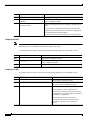
Configuring HSA Operation Task List
Before you configure HSA, decide how you intend to use HSA, as described in the “HSA
Implementation Methods” section on page 25. Do you want it for simple hardware backup or for
software error protection? If you are using new or experimental Cisco IOS software, consider using the
software error protection method; otherwise, use the simple hardware backup method.
After determining how you intend to use HSA, complete the tasks in the following sections. The first
two and last two tasks are required for both implementations. The third and fourth tasks relate to simple
hardware backup. The fifth task relates to software error protection only.
•
OL-4923-01 B0
Specifying the Default Standby RSP2, page 26 (both implementations)
25
Note
•
Ensuring That Both RSPs Contain the Same Configuration File, page 27 (both implementations)
•
Ensuring that Both RSPs Contain the Same System Image, page 27 (simple hardware backup only)
•
Ensuring that Both RSPs Contain the Same Microcode Image, page 29 (simple hardware backup
only)
•
Specifying Different Startup Images for the Active and the Standby RSPs, page 30 (software error
protection only)
•
Manually Setting Environment Variables on the Standby RSP, page 37 (both implementations)
•
Automatically Setting Environment Variables on the Standby RSP, page 37 (both implementations)
The following HSA configuration examples refer to a Cisco 7513. If you have a Cisco 7507, the primary
difference is that the active and the standby RSPs are located in slots 2 and 3, respectively.
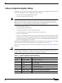
Specifying the Default Standby RSP2
Your view of the environment is always from the active RSP2 perspective, you must define a default
standby RSP2. The router uses the default standby information when booting.
•
If a system boot is due to powering up the router or using the reload command, then the specified
default standby is the standby RSP2.
•
If a system boot is due to a system crash or hardware failure, then the system ignores the default
standby designation and makes the crashed or faulty RSP2 the standby RSP2.
To define the default standby RSP2, use the following commands in Table 4 in privileged EXEC mode:
Table 4
Defining the Default Standby RSP
Command
Description
Step 1
Router# configure terminal
Enters the configuration mode from the terminal.
Step 2
Router(config)# slave default-slot
processor-slot-number
Defines the default standby RSP2 (or RSP4/4+).
Step 3
Router(config)# end
Exits configuration mode.
Step 4
Router# copy system: running-config nvram:startup-config
Saves this information to your startup
configuration.
Upon the next system reboot, the above changes take effect (if both RSP2 cards are operational). Thus,
the specified default standby becomes the standby RSP2 card. The other RSP2 card takes over control
of the system and controls all functions of the router.
If you do not specifically define the default standby RSP2, the RSP2 card located in the higher number
processor slot is the default standby. On the Cisco 7507, processor slot 3 contains the default standby
RSP. On the Cisco 7513, processor slot 7 contains the default standby RSP.
The following example sets the default standby RSP2 to processor slot 2 on a Cisco 7507:
Router# configure terminal
Router (config)# slave default-slot 2
Ctrl-Z
Router# copy running-config startup-config
26
OL-4923-01 B0
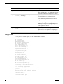
Ensuring That Both RSPs Contain the Same Configuration File
With the simple hardware backup and software error protection implementation methods, you always
want your active and standby configuration files to match. To ensure that they match, turn on automatic
synchronization. In automatic synchronization mode, the active copies its startup configuration to the
standby’s startup configuration when you issue a copy command that specifies the active’s startup
configuration (nvram:startup-config) as the target.
Automatic synchronization mode is on by default; however, to turn it on manually, use the following
commands in Table 5, in privileged EXEC mode:
Table 5
Ensuring that Both RSPs Have the Same Configuration File
Command
Description
Step 1
Router# configure terminal
Enters the configuration mode from the terminal.
Step 2
Router(config)# slave auto-sync config
Turns on the automatic synchronization mode.
Step 3
Router(config)# end
Exits configuration mode.
Step 4
Router# copy system: running-config nvram:startup-config
Saves this information to your startup configuration
and copies the configuration to the standby’s
startup configuration.
The following example turns on automatic configuration file synchronization:
Router# configure terminal
Router (config)# slave auto-sync config
Router (config)# end
Router# copy system:running-config nvram:startup-config
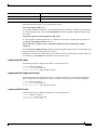
Ensuring that Both RSPs Contain the Same System Image
For simple hardware backup, ensure that both RSP cards have the same system image.
To ensure that both RSPs have the same system image, use the following commands in Table 6 in
privileged EXEC mode:
Table 6
Confirming the Same System Image on Both RSPs
Step
Command
Description
Step 1
Router# show bootvar
Displays the contents of the BOOT environment variable
to learn the current booting parameters for the active and
the standby RSP.
Step 2
Router# dir {bootflash: | slot0: | slot1:}
Verifies the location and version of the active RSP
software image.
Step 3
Router# dir {slavebootflash: | slaveslot0: | slaveslot1:}
Determines if the standby RSP contains the same
software image in the same location.
Step 4
Router# copy {bootflash:[filename]| slot0:[filename] |
slot1:[filename]}{slavebootflash:[filename] | slaveslot0:[filename] |
slaveslot1:[filename]}
If the standby RSP does not contain the same system
image in the same location, copies the active’s system
image to the appropriate standby location.
Note that you might also have to use the delete and/or
Note that deleted space is not reusable until after you
squeeze command in conjunction with the copy
perform the squeeze command.
command to accomplish this step.
OL-4923-01 B0
27
Note
Standard 16-, and 20-MB Flash memory cards are supported with the RSP2 (The 20-MB Flash memory
card is currently the default.). See Flash Memory Card Installation Instructions for detailed information.
You should specify slot0 or slot1 in your command, depending on which slot you are using.
Standard 48- and 128-MB Flash Disks are supported with the RSP2. See Using the Flash Disk for
additional information. You should specify slot0 or slot1 in your command, depending on which slot
your are using.
The following example ensures that both RSPs have the same system image. Note that because no
environment variables are set, the default environment variables are in effect for both the active and the
standby RSP.
Router# show bootvar
BOOT variable =
CONFIG_FILE variable =
Current CONFIG_FILE variable =
BOOTLDR variable does not exist
Configuration register is 0x0
Slave auto-sync config mode is on
current slave is in slot 7
BOOT variable =
CONFIG_FILE variable =
BOOTLDR variable does not exist
Configuration register is 0x0
Router# dir slot0:
-#- -length- -----date/time------ name
1
3482498 May 4 1999 21:38:04 rsp-k-mx11.2
7993896 bytes available (1496 bytes used)
Router# dir slaveslot0:
-#- -length- -----date/time------ name
1
3482498 May 4 1999 21:38:04 rsp-k-mx11.1
7993896 bytes available (1496 bytes used)
Router# delete slaveslot0:rsp-k-mx11.1
Router# copy slot0:rsp-k-mx11.2 slaveslot0:rsp-k-mx11.2
28
OL-4923-01 B0
Ensuring that Both RSPs Contain the Same Microcode Image
To ensure that both RSPs have the same microcode images, use the following commands in Table 7 in
privileged EXEC mode:
Table 7
Confirming That Both RSPs Have the Same Microcode Images
Step
Command
Description
Step 1
Router# show controller cbus
Determines the microcode images used on the
interface processors. If all interface processors are
running from the bundled system microcode, no
further action is required.
Step 2
Router# dir {bootflash: | slot0: | slot1:}
If any interface processors are running from the
Flash memory file system, verifies the location and
version of the active RSP supplementary microcode.
Step 3
Router# dir {slavebootflash: | slaveslot0: |
slaveslot1:}
Determines whether the standby RSP contains the
same microcode image in the same location.
Step 4
Router# copy {bootflash:[filename] |
slot0:[filename] | slot1:[filename]}
{slavebootslot:[filename] | slaveslot0:[filename] |
slaveslot1:[filename]}
If the standby RSP does not contain the same
microcode image in the same location, copies the
active’s microcode image to the appropriate standby
location.
Note that you might also have to use the delete and/or
squeeze command in conjunction with the copy command
to accomplish this step.
Note that deleted space is not reusable until after you
perform the squeeze command.
The following example ensures that both RSPs have the same microcode image. Notice that slots 0, 1,
4, 9, and 10 load microcode from the bundled software, as noted by the statement “software loaded from
system.” The Channel Interface Processor (CIP2) in slot 11 does not use the microcode bundled with the
system. Instead, it loads the microcode from slot0:pond/bath/rsp_fsip20-1. Thus, you must ensure that
the standby RSP2 has a copy of the same FSIP microcode in the same location.
Router# show controller cbus
MEMD at 40000000, 2097152 bytes (unused 416, recarves 3, lost 0)
RawQ 48000100, ReturnQ 48000108, EventQ 48000110
BufhdrQ 48000128 (2948 items), LovltrQ 48000140 (5 items, 1632
IpcbufQ 48000148 (16 items, 4096 bytes)
3571 buffer headers (48002000 - 4800FF20)
pool0: 28 buffers, 256 bytes, queue 48000130
pool1: 237 buffers, 1536 bytes, queue 48000138
pool2: 333 buffers, 4544 bytes, queue 48000150
pool3: 4 buffers, 4576 bytes, queue 48000158
slot0: EIP, hw 1.5, sw 20.00, ccb 5800FF30, cmdq 48000080, vps
software loaded from system
Ethernet0/0, addr 0000.0ca3.cc00 (bia 0000.0ca3.cc00)
gfreeq 48000138, lfreeq 48000160 (1536 bytes), throttled 0
rxlo 4, rxhi 42, rxcurr 0, maxrxcurr 2
txq 48000168, txacc 48000082 (value 27), txlimit 27
.........
slot1: FIP, hw 2.9, sw 20.02, ccb 5800FF40, cmdq 48000088, vps
software loaded from system
Fddi1/0, addr 0000.0ca3.cc20 (bia 0000.0ca3.cc20)
gfreeq 48000150, lfreeq 480001C0 (4544 bytes), throttled 0
rxlo 4, rxhi 165, rxcurr 0, maxrxcurr 0
txq 480001C8, txacc 480000B2 (value 0), txlimit 95
slot4: AIP, hw 1.3, sw 20.02, ccb 5800FF70, cmdq 480000A0, vps
software loaded from system
OL-4923-01 B0
bytes)
4096
4096
8192
29
ATM4/0, applique is SONET (155Mbps)
gfreeq 48000150, lfreeq 480001D0 (4544 bytes), throttled 0
rxlo 4, rxhi 165, rxcurr 0, maxrxcurr 0
txq 480001D8, txacc 480000BA (value 0), txlimit 95
slot9: MIP, hw 1.0, sw 20.02, ccb 5800FFC0, cmdq 480000C8, vps 8192
software loaded from system
T1 9/0, applique is Channelized T1
gfreeq 48000138, lfreeq 480001E0 (1536 bytes), throttled 0
rxlo 4, rxhi 42, rxcurr 0, maxrxcurr 0
txq 480001E8, txacc 480000C2 (value 27), txlimit 27
.......
slot
10: TRIP, hw 1.1, sw 20.00, ccb 5800FFD0, cmdq 480000D0, vps 4096
software loaded from system
TokenRing10/0, addr 0000.0ca3.cd40 (bia 0000.0ca3.cd40)
gfreeq 48000150, lfreeq 48000200 (4544 bytes), throttled 0
rxlo 4, rxhi 165, rxcurr 1, maxrxcurr 1
txq 48000208, txacc 480000D2 (value 95), txlimit 95
.........
slot11: FSIP, hw 1.1, sw 20.01, ccb 5800FFE0, cmdq 480000D8, vps 8192
software loaded from flash slot0:pond/bath/rsp_fsip20-1
Serial11/0, applique is Universal (cable unattached)
gfreeq 48000138, lfreeq 48000240 (1536 bytes), throttled 0
rxlo 4, rxhi 42, rxcurr 0, maxrxcurr 0
txq 48000248, txacc 480000F2 (value 5), txlimit 27
...........
Router# dir slot0:pond/bath/rsp_fsip20-1
-#- -length- -----date/time------ name
3
10242
Jan 01 1999 03:46:31 pond/bath/rsp_fsip20-1
Router# dir slaveslot0:pond/bath/rsp_fsip20-1
No such file
4079832 bytes available (3915560 bytes used)
Router# copy slot0:pond/bath/rsp_fsip20-1 slaveslot0:
4079704 bytes available on device slaveslot0, proceed? [confirm]
Router# dir slaveslot0:pond/bath/rsp_fsip20-1
-#- -length- -----date/time------ name
3
10242
Mar 01 1999 02:35:04 pond/bath/rsp_fsip20-1
4069460 bytes available (3925932 bytes used)
Router#
Specifying Different Startup Images for the Active and the Standby RSPs
For software error protection, the RSPs should have different system images.
When the factory sends you a new router with two RSP2s, you receive the same system image on both
RSPs. To configure the HSA feature for software error protection, you need two separate software
images on the RSPs. You copy a desired image to the active RSP card and modify the boot system
commands to reflect booting two separate system images. Each RSP uses its own image to boot the router
when it becomes the active.
30
OL-4923-01 B0
To specify different startup images for the active and the standby RSPs, use the following commands in
Table 8 in privileged EXEC mode:
Table 8
Specifying Different Startup Images for the Active and Standby RSP
Step
Command
Description
Step 1
Router# dir {bootflash: | slot0: | slot1:}
Verifies the location and version of the active RSP software
image.
Step 2
Router# dir {slavebootflash: | slaveslot0:
| slaveslot1:}
Determines whether the standby RSP contains the same software
image in the same location.
Step 3
Router# copy source {bootflash: | slot0: |
slot1:}
Copies a different system image to the active RSP.
Step 4
Router# configure terminal
Enters configuration mode from the terminal.
Step 5
Router# boot system flash
bootflash:[filename]
boot system flash slot0:[filename]
boot system flash slot1:[filename]
From global configuration mode, configures the active RSP to
boot the new image from the appropriate location.
Step 6
Router# boot system flash
bootflash:[filename]
boot system flash slot0:[filename]
boot system flash slot1:[filename]
Also, adds a boot system command that specifies the standby
RSP boot image and location. This is the boot image that the
standby uses when it becomes the active RSP and boots the
system. Note that because the standby boots this image when the
standby is actually the new active RSP, the command syntax
does not use a “standby” prefix.
Step 7
Router# boot system [rcp| tftp | ftp}
[filename] [ip-address]
(Optional) Configures the active RSP to boot from a network
server.
Step 8
Router# config-register value 1
Sets the configuration register to enable loading of the system
image from a network server or Flash memory.
Step 9
Router# end
Exits configuration mode.
Step 10
Router# copy running-config
nvram:startup-config
Saves the configuration file to the active RSP startup
configuration. Because automatic synchronization is turned on,
this step saves the boot system commands to the active and the
standby startup configuration.
Step 11
Router# reload
Resets the router with the new configuration information.
1. See the “Replacing and Upgrading DRAM SIMMs” section on page 71 for more information on systems that can use this command to modify the software
configuration register.
Upgrading to a New Software Version Example
Note
The following examples show systems with two RSP2s.
In the following example, assume the following:
OL-4923-01 B0
•
The active RSP2 is in processor slot 6, and the standby RSP2 is in processor slot 7 of a Cisco 7513.
•
The system has the same image, rsp-k-mx11.1, in PC Card slot 0 of both the active and the standby
RSP.
•
You want to upgrade to Cisco IOS Release 12.1(13)E, but you want to guard against software
failures. So you must configure HSA operation for software error protection.
31
Figure 8 illustrates the software error protection configuration for this sample scenario. The
configuration commands for this configuration follow the figure.
Figure 8
Software Error Protection—Upgrading to a New Software Version
NO
NO
RM
RM
AL
AL
EN
AB
LE
slot0:rsp-k-mx11.1
slot0:rsp-k-mx11.2
SL SL
OT OT
0 1
AC
TI
DBY VE
ST
AN
Active RSP card
Flash memory
slot0:rsp-k-mx11.1
SL SL
OT OT
0 1
AC
TI
DBY VE
ST
AN
ST
Standby RSP card
Flash memory
ST
AN
AN
DBY
DBY
/A
/A
CTI
CTI
VE
VE
CPU
CPU
HAL
HAL
T
T
EN
AB
RES
ET
AU
AU
X
CO
LE
RES
ET
X
CO
NSO
NSO
LE
57290
LE
config.file
boot system flash slot0:rsp-k-mx11.2
boot system flash slot0:rsp-k-mx11.1
.
.
.
Step 1
Because you always view the environment from the active RSP’s perspective, in the following command
you view the active PC Card slot 0 to verify the location and version of the active software image:
Router# dir slot0:
-#- -length- -----date/time------ name
1
3482496 May 4 1999 21:38:04 rsp-k-mx11.1
7993896 bytes available (1496 bytes used)
Step 2
Now view the standby software image location and version:
Router# dir slaveslot0:
-#- -length- -----date/time------ name
1
3482496 May 4 1999 21:38:04 rsp-k-mx11.1
7993896 bytes available (1496 bytes used)
Step 3
Because you want to run the Cisco IOS Release 12.1(12)E system image on one RSP and the Cisco IOS
Release 12.1(13)E system image on the other RSP, copy the Cisco IOS Release 12.1(13)E system image
to the active’s slot 0:
Router# copy tftp slot0:rsp-k-mx11.1
32
OL-4923-01 B0
Step 4
Enter global configuration mode and configure the system to boot first from a Cisco IOS Release
12.1(13)E system image and then from a Cisco IOS Release 12.1(12)E system image.
Router# configure terminal
Router (config)# boot system flash slot0:rsp-k-mx11.2
Router (config)# boot system flash slot0:rsp-k-mx11.1
With this configuration, when the slot 6 RSP is active, it looks first in its PC Card slot 0 for the system
image file rsp-k-mx11.2 to boot. Finding this file, the router boots from that system image. When the slot
7 RSP is active, it also looks first in its slot 0 for the system image file rsp-k-mx11.2 to boot. Because
that image does not exist in that location, the slot 7 RSP looks for the system image file rsp-k-mx11.1 in
slot 0 to boot. Finding this file in its PC Card slot 0, the router boots from that system image. In this way,
each RSP can reboot the system using its own system image when it becomes the active RSP.
Step 5
Configure the system further with a fault-tolerant booting strategy:
Router (config)# boot system tftp rsp-k-mx11.1 1.1.1.25
Step 6
Set the configuration register to enable loading of the system image from a network server or from Flash
memory and save the changes to the active and the standby startup configuration file:
Router (config)# config-register 0x010F
Router (config)# Ctrl-Z
Router# copy running-config startup-config
Step 7
Reload the system so that the active RSP uses the new Release 12.1(12)S system image:
Router# reload
This completes the sample procedure for upgrading to a new software version.
Backing Up with an Older Software Version Example
In the following sample scenario, assume the following:
OL-4923-01 B0
•
The active RSP is in processor slot 6, and the standby RSP is in processor slot 7 of a Cisco 7513.
•
The system has the same image, rsp-k-mx11.2, in PC Card slot 0 of both the active and the standby
RSPs.
•
You want to use Cisco IOS Release 12.1(12)E as backup to guard against software failures, so you
configure HSA operation for software error protection.
33
In this scenario, you begin with the configuration shown in Figure 9.
Figure 9
Software Error Protection—Backing Up with an Older Software Version, Part I
NO
NO
RM
RM
AL
AL
EN
AB
LE
slot0:rsp-k-mx11.2
SL SL
OT OT
0 1
AC
TI
DBY VE
ST
AN
Active RSP card
Flash memory
slot0:rsp-k-mx11.2
SL SL
OT OT
0 1
AC
TI
DBY VE
ST
AN
ST
Standby RSP card
Flash memory
ST
AN
AN
DBY
DBY
/A
/A
CTI
CTI
VE
VE
CPU
CPU
HAL
HAL
T
T
EN
AB
RES
LE
RES
ET
ET
AU
AU
X
X
CO
CO
NSO
NSO
LE
57291
LE
Next, you copy the rsp-k-mx11.1 image to the active and the standby RSPs, as shown in Figure 10.
Figure 10
Software Error Protection—Backing Up with an Older Software Version, Part II
NO
NO
RM
RM
AL
AL
EN
AB
LE
slot0:rsp-k-mx11.2
slot0:rsp-k-mx11.1
SL SL
OT OT
0 1
AC
TI
DBY VE
ST
AN
Active RSP card
Flash memory
slot0:rsp-k-mx11.2
slot0:rsp-k-mx11.1
SL SL
OT OT
0 1
AC
TI
DBY VE
ST
AN
ST
Standby RSP card
Flash memory
ST
AN
AN
DBY
DBY
/A
/A
CTI
CTI
VE
VE
CPU
CPU
HAL
HAL
T
T
EN
AB
RES
ET
AU
AU
X
CO
LE
RES
ET
X
CO
NSO
NSO
LE
57292
LE
34
OL-4923-01 B0
Last, delete the rsp-k-mx11.2 image from the standby RSP, as shown in Figure 11:
Figure 11
Software Error Protection—Backing Up with an Older Software Version, Part III
NO
NO
RM
RM
AL
AL
EN
AB
LE
slot0:rsp-k-mx11.1
slot0:rsp-k-mx11.2
SL SL
OT OT
0 1
Active RSP card
Flash memory
slot0:rsp-k-mx11.1
SL SL
OT OT
0 1
M
AV ASTE
E
R
SL
M
AV ASTE
E
R
SL
SL
Standby RSP card
Flash memory
SL
AV
AV
E/
E/
MAS
MAS
TE
TE
R
R
CPU
CPU
HAL
HAL
T
T
EN
AB
RES
ET
AU
AU
X
CO
LE
RES
ET
X
CO
NSO
NSO
LE
57293
LE
config.file
boot system flash slot0:rsp-k-mx11.2
boot system flash slot0:rsp-k-mx11.1
.
.
.
The following commands configure software error protection for this sample scenario:
Step 1
View the active and the standby slot 0 to verify the location and version of their software images:
Router# dir slot0:
-#- -length- -----date/time------ name
1
3482498 May 4 1999 21:38:04 rsp-k-mx11.2
7993896 bytes available (1496 bytes used)
Router# dir slaveslot0:
-#- -length- -----date/time------ name
1
3482498 May 4 1999 21:38:04 rsp-k-mx11.2
7993896 bytes available (1496 bytes used)
Step 2
Copy the Release 12.1(12)E system image to the active and the standby PC Card slot 0:
Router# copy tftp slot0:rsp-k-mx11.1
Router# copy tftp slaveslotk0:rsp-k-mx11.1
Step 3
Delete the rsp-k-mx11.2 image from the standby RSP:
Router# delete slaveslot0:rsp-k-mx11.2
OL-4923-01 B0
35
Step 4
Configure the system to boot first from a Release 12.1(13)E system image and then from a Release
12.1(12)E system image:
Router# configure terminal
Router (config)# boot system flash slot0:rsp-k-mx11.2
Router (config)# boot system flash slot0:rsp-k-mx11.1
Step 5
Configure the system further with a fault-tolerant booting strategy:
Router(config)# boot system tftp rsp-k-mx11.1 1.1.1.25
Step 6
Set the configuration register to enable loading of the system image from a network server or from Flash
memory and save the changes to the active and the standby startup configuration file:
Router(config)# config-register 0x010F
Router (config)# Crtl-Z
Router# copy system: running-config startup-config
Note
You do not need to reload the router in this example, because the router is currently running the
Release 12.1(13)E image.
This completes the sample procedure for backing up with an older software version.
Setting Environment Variables on the Active and the Standby RSPs
You can optionally set environment variables on both RSPs in a Cisco 7507 and Cisco 7513.
Note
When you configure the HSA operation, we recommend that you use the default environment variables.
If you do change the variables, we recommend that you set the same device for equivalent environment
variables on each RSP. For example, if you set one RSP CONFIG_FILE environment variable to
NVRAM, then set the other RSP CONFIG_FILE environment variable to NVRAM also.
You set environment variables on the active RSP just as you would if it were the only RSP in the system.
You can set the same environment variables on the standby RSP manually or automatically.
The following sections describe these two methods:
•
Manually Setting Environment Variables on the Standby RSP, page 37
•
Automatically Setting Environment Variables on the Standby RSP, page 37
For more complete configuration information on how to set environment variables, refer to the
Configuration Fundamentals Configuration Guide and the Configuration Fundamentals Command
Reference publications, which are available online, on the Documentation CD-ROM, or as printed
documents.
36
OL-4923-01 B0
Manually Setting Environment Variables on the Standby RSP
Once you set the active RSP environment variables, you can manually set the same environment
variables on the standby RSP using the slave sync config command.
To manually set environment variables on the standby RSP, use the following commands in Table 9 in
privileged EXEC mode:
Table 9
Manually Setting Environment Variables on the Standby RSP
Step
Command
Description
Step 1
Router# boot system
boot config
Sets the active RSP environment variables. For more complete
HSA configuration information, refer to the Configuration
Fundamentals Configuration Guide and the Configuration
Fundamentals Command Reference publications, which are
available on the Documentation CD-ROM, online, or as printed
documents.
Step 2
Router# copy running-config
startup-config
Saves the settings to the startup configuration. This also puts the
information under the RSP’s ROM monitor control.
Step 3
Router# slave sync config
Saves the same environment variables to the standby RSP by
manually synchronizing their configuration files.
Step 4
Router# show bootvar
Verifies the environment variable settings.
boot bootldr
Automatically Setting Environment Variables on the Standby RSP
With automatic synchronization turned on, when you set the active RSP environment variables and save
them, the system automatically saves the same environment variables to the standby’s startup
configuration.
Note
Automatic synchronization mode is on by default.
To set environment variables on the standby RSP when automatic synchronization is on, use the
following commands in Table 10 in privileged EXEC mode:
Table 10
Setting Environment Variables on the Standby RSP with Automatic Synchronization On
Step
Command
Description
Step 1
Router# boot system
boot config
Sets the active RSP environment variables. For more complete
HSA configuration information, refer to the Configuration
Fundamentals Configuration Guide and the Configuration
Fundamentals Command Reference publications, which are
available on the Documentation CD-ROM, online, or as printed
documents.
Step 2
Router# copy running-config
startup-config
Saves the settings to the startup configuration. This also puts the
information under that RSP’s ROM monitor control.
Step 3
Router# show bootvar
Verifies the environment variable settings.
boot bootldr
OL-4923-01 B0
37
Monitoring and Maintaining HSA Operation
To monitor and maintain HSA operation, you can override the standby image that is bundled with the
active image. To do so, perform the following task in global configuration mode:
Note
Command
Task
hw-module slot image
Specifies which image the standby runs.
The slave image system command, previously used to determine which image the standby runs, is not
valid with newer HA images.
You can manually synchronize configuration files and ROM monitor environment variables on the active
and the standby RSPs. To do so, perform the following task in privileged EXEC mode:
Caution
Command
Task
slave sync config
Manually synchronizes active and standby configuration
files.
When you install a second RSP for the first time, you must immediately configure it using the slave
sync config command. This ensures that the new standby is configured consistently with the active.
Failure to do so might result in an unconfigured standby RSP taking control of the router when the
active fails, rendering the network inoperable.
The slave sync config command is also a useful tool for more advanced implementation methods not
discussed in this document. Refer to the Configuration Fundamentals Configuration Guide and the
Configuration Fundamentals Command Reference publications, which are available on the
Documentation CD-ROM, online, or as printed documents.
Enabling High Availability Features
This section discusses the following topics:
•
High Availability Features, page 39
•
Hardware and Software Prerequisites, page 40
•
Installation Procedures, page 41
– Configuring RPR and RPR+, page 43
– Configuring SLCR, page 59
– Configuring NonStop Forwarding (NSF), page 49
– Performing a Fast Software Upgrade, page 56
– Configuring SLCR, page 59
•
38
RPR, RPR+, SSO, and FSU Troubleshooting Tips, page 58
OL-4923-01 B0
High availability (HA), an alternative to the default high system availability (HSA) feature, is a series
of features that minimizes system downtime through a “warm standby.” Warm standby allows the system
to switch over to a standby RSP preloaded with a Cisco IOS image in 30 seconds to 5 minutes, depending
on the feature. For more information on high service availability (HSA), the system default program,
refer to the “Configuring High System Availability” section on page 23. Like HSA, HA is supported on
the Cisco 7507 and the Cisco 7513 routers with two RSP2s, or with one RSP2 and one RSP4/4+.
A router configured for HA has two RSPs, an active RSP and a standby RSP. The active RSP controls
all functions of the router, and the standby RSP monitors the active for failure.
High Availability Features
HA features include:
•
Single Line Card Reload (SLCR)—Speeds recovery of a failed router by reloading a failed line card
without reloading other line cards on the network backplane. SLCR isolates the fault to a single
Versatile Interface Processor (VIP2 or VIP4) or Legacy interface processor card, and accelerates
recovery time by reloading only the faulty VIP or Legacy interface processor card. Physical lines
and routing protocols on the other line cards of the network backplane remain active. The system
continues forwarding packets with minimal interruptions.
SLCR is disabled by default and needs to be manually configured. When SLCR is enabled, and more
than two linecards crash simultaneously, all line cards will be reset.
For more information on how to configure SLCR, refer to the Cisco 7500 Single Line Card Reload
feature module at
http://www.cisco.com/univercd/cc/td/doc/product/software/ios120/120newft/120limit/120s/120s13
/slcr.htm.
•
Route Processor Redundancy (RPR)—Speeds recovery of a failed router by accelerating switchover
to the standby RSP. The standby RSP is preinitialized with the same full Cisco IOS software image
as on the active RSP. When the active RSP fails, the standby RSP takes over. The line cards are OIR
inserted by the standby RSP during the switchover. Switchover time is reduced to 4 to 5 minutes
with RPR.
RPR is disabled by default, and needs to be manually configured. For more information on RPR,
refer to the Route Processor Redundancy and Fast Software Upgrade on Cisco 7500 Series Routers
feature module available online at
http://www.cisco.com/univercd/cc/td/doc/product/software/ios120/120newft/120limit/120st/120st
16/st_rpr7x.htm.
•
Route Processor Redundancy Plus (RPR+)—Like RPR, RPR+ speeds recovery of a failed router by
accelerating switchover to the standby RSP. The RPR+ feature, an enhancement of RPR, prevents a
VIP from being reset and reloaded when a switchover occurs between the active and standby RSPs.
Because VIPs are not reset and microcode is not reloaded on the VIPs, and the time needed to parse
the configuration is eliminated, switchover time is reduced to 30 to 40 seconds.
Online removal of the active RSP causes all line cards to reset and reload, which is equivalent to an
RPR switchover, and results in a longer switchover time. When it is necessary to remove the active
RSP from the system, first issue a switchover command to switch from the Active RSP to the
Standby RSP.
RPR+ is disabled by default, and needs to be manually configured. RPR+ does not support the
Legacy interface processor card. The system will default to RPR if the router includes an Legacy
interface processor card. For more information on how to configure RPR+, refer to the RPR+ on
OL-4923-01 B0
39
Cisco 7500 Series Routers feature module, available online at
http://www.cisco.com/univercd/cc/td/doc/product/software/ios120/120newft/120limit/120st/120st19/st
_rpr2.htm.
•
Fast Software Upgrade (FSU)—Accelerates switchover to a new software image. Fast Software
Upgrade permits users to upgrade to an interim release or next minor release Cisco IOS image by
uploading it to the standby RSP first. After loading the new Cisco IOS image on the standby RSP,
the user can issue a command to switch to the standby RSP, and all the line cards will be reloaded,
similar to what occurs in RPR. This feature allows users to upgrade Cisco IOS on their Cisco 7500
routers with much less interruption to service than previously experienced.
For more information on FSU, refer to the Route Processor Redundancy and Fast Software Upgrade
on Cisco 7500 Series Routers feature module available online at
http://www.cisco.com/univercd/cc/td/doc/product/software/ios120/120newft/120limit/120st/120st
16/st_rpr7x.htm.
•
Stateful Switchover (SSO)—Based on RPR+, SSO allows the active RSP to pass the necessary state
information of key routing and interface protocols to the standby RSP upon switchover, which
reduces the time for the standby RSP to learn and converge routes.
SSO is disabled by default, and needs to be manually configured. SSO does not support the Legacy
interface processor cards. For more information on how to configure SSO, refer to the Stateful
Switchover feature module available online at
http://www.cisco.com/univercd/cc/td/doc/product/software/ios120/120newft/120limit/120s/120s22/sso
120s.htm.
•
Cisco Nonstop Forwarding (NSF) —Used with SSO, NSF allows routers with redundant RSPs to
continue forwarding data to the standby RSP during a switchover. This feature uses the Forwarding
Information Base (FIB) that was current at the time of the switchover. Once the routing protocols
have converged, the FIB table is updated and stale route entries are deleted. This feature eliminates
downtime during the switchover. Note: Cisco NSF always runs together with SSO.
Cisco NSF is supported by the BGP, OSPF, and IS-IS protocols for routing and by Cisco Express
Forwarding (CEF) for forwarding. For more information on how to configure NSF, see the Cisco
Nonstop Forwarding feature module available online at
http://www.cisco.com/univercd/cc/td/doc/product/software/ios120/120newft/120limit/120s/120s22
/nsf120s.htm.
Hardware and Software Prerequisites
The RPR and FSU features are available on the Cisco 7507 and Cisco 7513 routers, which are loaded
with two route switch processors (RSPs). The router is loaded with two route switch processors (RSPs),
which can be two RSP2s, or an RSP2 and an RSP4/4+.
40
•
Single Line Card Reload (SLCR)—Cisco IOS Releases 12.0(13)S, 12.1(4)T, and 12.1(5)E
•
Route Processor Redundancy (RPR)— Cisco IOS Release 12.0(16)ST
•
Route Processor Redundancy Plus (RPR+)— Cisco IOS Release 12.0(19)ST
•
Fast Software Upgrade (FSU)—Cisco IOS Release 12.0(16)ST
•
Stateful Switchover (SSO) —Cisco IOS Release 12.0(22)S
•
Non-Stop Forwarding (NSF)—Cisco IOS Release 12.0(22)S
OL-4923-01 B0
Installation Procedures
See the following sections for the configuration tasks required to run the RPR/RPR+, SSO with NSF,
FSU, and SLCR features.
•
Enabling the Router, page 41 (required)
•
Copying an Image onto an RSP, page 42 (required)
•
Setting the Config-Register Boot Variable, page 43 (optional)
•
Configuring RPR and RPR+, page 43 (optional)
•
Configuring SLCR, page 59 (optional)
•
Configuring NonStop Forwarding (NSF), page 49 (optional; but SSO required)
•
Performing a Fast Software Upgrade, page 56 (optional)
•
RPR, RPR+, SSO, and FSU Troubleshooting Tips, page 58 (optional)
•
Configuring SLCR, page 59 (optional)
Enabling the Router
Step 1
At the user-level EXEC prompt, enter the enable command. The EXEC prompts you for a
privileged-level password as follows:
Router> enable
Password:
Step 2
Enter the password (the password is case sensitive). For security purposes, the password is not displayed.
When you enter the correct password, the system displays the privileged-level system prompt (#):
Router#
The completes the enabling the router procedure.
OL-4923-01 B0
41
Copying an Image onto an RSP
Use TFTP to copy a high availability Cisco IOS image onto the active and standby RSPs:
Step 1
Command
Purpose
Router# copy tftp slotslot-number:
Uses TFTP to copy a high availability Cisco IOS
image onto the Flash memory card of the active RSP.1
•
Address or name of remote host []? ip-address
The router prompts you for the IP address of the
TFTP server.
•
Name of file to copy []? imagename<Return>
writing filename!!!!!!!!!!!!!!!!!!!!!!!!!!!!!!!!!!!!
slotslot-number—Specifies the Flash memory
card of the active RSP.
ip-address—Specifies the IP address of the TFTP
server that contains the new image.
The router prompts you for the name of the image file
you are copying to the Flash memory card.
•
imagename—Indicates the name of the image to
be loaded onto the Flash memory card.
The router prompts you to enter the name under
which you want the file to appear at the destination.
Destination filename? [imagename1] <Return>
Accessing tftp://host ip-address/file 'imagename' on
ip-address.. found !
11188128 bytes copied in 2280.664 secs (4906
bytes/sec)
Step 2
Router# copy tftp slaveslotslot-number:
•
Uses TFTP to copy a high availability Cisco IOS
image onto the Flash memory card of the standby
RSP.
•
Address or name of remote host []? ip-address
Name of file to copy []? imagename<Return>
writing
filename!!!!!!!!!!!!!!!!!!!!!!!!!!!!!!!!!!!!!!!!!!!
imagename1—Indicates the name of the image
as it appears at the destination.
slaveslotslot-number—Specifies the Flash
memory card of the standby RSP.
The router prompts you for the IP address of the
TFTP server.
•
ip-address—Specifies the IP address of the TFTP
server that contains the new image.
The router prompts you for the name of the image file
you are copying to the Flash memory card.
Destination filename? [imagename1] <Return>
Accessing file 'imagename' on ip-address.. found !
903500 bytes available for writing without erasure.
Loading imagename from ip-address (via Ethernet1/0):
!
[OK - 3320245/4194176 bytes]
•
imagename—Indicates the name of the image to
be loaded onto the Flash memory card.
The router prompts you to enter the name under
which you want the file to appear at the destination.
•
imagename1—Indicates the name of the image
as it appears at the destination.
1. Before you copy a file to Flash memory, be sure there is ample space available in Flash memory. Compare the size of the file you are copying to the
amount of available Flash memory shown. If the space available is less than the space required by the file you will copy, the copy process will continue,
but the entire file will not be copied into Flash memory.
42
OL-4923-01 B0
Setting the Config-Register Boot Variable
Though it is not required, we recommend that you modify the software configuration register boot field
so that the system boots the same image that the hw-module slot slot-number image file-spec command
specifies in the “Configuring RPR and RPR+” section on page 43.
Command
Purpose
Step 1
Router# show version
Obtains the current configuration register setting.
Step 2
Router# configure terminal
Enters configuration mode, selecting the terminal
option.
Step 3
Router(config)# boot system flash
slotslot-number:[imagename]
Specifies the filename of an image stored in Flash
memory.
Step 4
Router(config)# config-register value
•
imagename—It is recommended that you set the
boot variable so that the system boots the same
image specified by the hw-module slot
slot-number image file-spec command. See
Step 2 of the “Configuring RPR and RPR+”
section on page 43.
•
slot-number—Specifies the active RSP slot
where the Flash memory card is located. Valid
numbers are slot 2 or slot 3 for a Cisco 7507
router and slot 6 or slot 7 for a Cisco 7513
router.
Modifies the existing configuration register setting
to reflect the way in which you want to load a system
image.
value—0x0 to 0xFFFFFFFF
Step 5
Router# Ctrl-Z
Exits configuration mode.
Step 6
Router# reload
Resets the router with the new configuration
information.
Configuring RPR and RPR+
Each task in the list is identified as either required or optional.
Note
OL-4923-01 B0
•
Configuring RPR and RPR+, page 43 (required)
•
Verifying RPR and RPR+, page 44 (optional)
•
Configuring RPR and RPR+ Example, page 45 (optional)
Online removal of the active RSP causes all line cards to reset and reload, which is the equivalent to an
RPR switchover, and results in a longer switchover time. When it is necessary to remove the active RSP
from the system, first issue a switchover command to switch from the active RSP to the standby RSP.
43
To configure RPR and RPR+, enter the commands as shown below:
Command
Purpose
Step 1
Router# configure terminal
Enters configuration mode.
Step 2
Router(config)# hw-module slot slot-number image
file-spec
Verifies that the specified image is compatible with
RPR and exists on the standby RSP. If a high
availability image is found, the running
configuration is updated.
Step 3
Router(config)# hw-module slot slot-number image
file-spec
•
slot-number—Specifies the standby RSP slot
where the Flash memory card is located. Valid
numbers are slot 2 or slot 3 for a Cisco 7507
router or slot 6 or slot 7 for a Cisco 7513 router.
•
file-spec—Indicates the flash device and the
name of the image on the standby RSP.
Verifies that the specified image is compatible with
RPR and exists on the active RSP. If a high
availability image is found, the running
configuration is updated.
•
slot-number—Specifies the active RSP slot
where the Flash memory card is located. Valid
numbers are slot 2 or slot 3 for a Cisco 7507
router or slot 6 or slot 7 for a Cisco 7513 router.
•
file-spec—Indicates the Flash device and the
name of the image on the active RSP.
Step 4
Router(config)# redundancy
Enters redundancy mode.
Step 5
Router(config-red)# mode rpr (Or mode rpr-plus)
Sets the redundancy mode to RPR (or RPR+) on
both the active and standby RSPs. HSA is the
default redundancy mode.
Step 6
Router(config-red)# exit
Exits redundancy mode.
Step 7
Router(config)# end
Exits configuration mode.
Step 8
Router# hw-module sec-cpu reset
Resets and reloads the standby RSP with the
specified Cisco IOS image and executes the image.
Note
If you do not specify a Cisco IOS image in
Step 2, this command loads and executes
the bundled default IOS standby image.
The system then operates in HSA mode.
Verifying RPR and RPR+
Use the show redundancy command to verify that RPR or RPR+ is enabled:
Router# show redundancy
Operating mode is sso
redundancy mode sso
hw-module slot 6 image disk0:rsp-pv-mz
hw-module slot 7 image disk0:rsp-pv-mz
Active High Availability version is 3.0
44
OL-4923-01 B0
Standby High Availability version is 3.0
Active in slot 6
Standby in slot 7
The system
The system
The system
Reason for
total uptime since last reboot is 2 weeks, 23 hours 41 minutes.
has experienced 4 switchovers.
has been active (become master) for 21 hours 1 minute.
last switchover:User forced.
Configuring RPR and RPR+ Example
In the following example, the active RSP is in slot 2 and the standby RSP is installed in slot 3 of a
Cisco 7507 router.
Router# copy tftp slot0:rsp-pv-mz
Router# copy tftp slaveslot0:rsp-pv-mz
Router# configure terminal
Router(config)# hw-module slot 2 image slot0:rsp-pv-mz
Router(config)# hw-module slot 3 image slot0:rsp-pv-mz
Router(config)# redundancy
Router(config-red)# mode rpr (Or mode rpr-plus)
Router(config-red)# exit
Router(config)# end
Router# hw-module sec-cpu reset
Router# show running-config
version 12.0
service timestamps debug uptime
service timestamps log uptime
no service password-encryption
service single-slot-reload-enable
!
hostname Router1
!
boot system rcp://path/to/image/rsp-boot-mz
boot system tftp://path/to/image/rsp-boot-mz
boot bootldr bootflash:rsp-boot-mz
enable password password
!
redundancy
mode rpr !--indicates Redundancy mode has been configured for RPR
!
hw-module slot 2 image slot0:rsp-pv-mz
hw-module slot 3 image slot0:rsp-pv-mz
ip subnet-zero
ip rcmd remote-username router1
ip cef distributed
ip host iphost 192.168.0.1
mpls traffic-eng auto-bw timers
!
!
controller T3 6/0/0
clock source line
!
!
interface Ethernet0/0/0
ip address 10.0.0.1 255.255.0.0
no ip directed-broadcast
ip route-cache distributed
no keepalive
.
.
.
OL-4923-01 B0
45
exec-timeout 0 0
history size 40
transport preferred none
transport input none
line aux 0
line vty 0 4
login
Configuring a Stateful Switchover (SSO)
Each task in the list is identified as either required or optional.
•
Configuring a Stateful Switchover (SSO), page 46 (required)
•
Configuring Frame Relay Autosynchronization LMI Sequence Numbers, page 47 (optional)
•
Verifying SSO, page 47 (optional)
To configure SSO, use the following commands beginning in privileged EXEC mode:
Command
Purpose
Step 1
Router# configure terminal
Enters configuration mode.
Step 2
Router(config)# hw-module slot slot-number image
file-spec
Specifies the image to be used by the active RSP at
initialization. If a high-availability image is found,
the running configuration is updated.
•
slot-number—Specifies the active RSP slot
where the Flash memory card is located. Valid
numbers are slot 2 or slot 3 for a Cisco 7507
router or slot 6 or slot 7 for a Cisco 7513
router.
•
file-spec—Indicates the Flash device and the
name of the image on the active RSP.
Note: Step 2 and Step 3 are the same; Step 2
applies to the active RSP and Step 3 applies to
the standby RSP.
Note The image indicated by the file-spec
attribute must be available on the local Flash
device. Remote protocols such a TFTP and remote
copy are not available.
46
OL-4923-01 B0
Step 3
Command
Purpose
Router(config)# hw-module slot slot-number image
file-spec
Specifies the image to be used by the standby RSP
at initialization. If a high-availability image is
found, the running configuration is updated.
•
slot-number—Specifies the active RSP slot
where the Flash memory card is located. Valid
numbers are slot 2 or slot 3 for a Cisco 7507
router or slot 6 or slot 7 for a Cisco 7513
router.
•
file-spec—Indicates the Flash device and the
name of the image on the active RSP.
Note: Step 2 and Step 3 are the same; Step 2
applies to the active RSP and Step 3 applies to
the standby RSP.
Note The image indicated by the file-spec
attribute must be available on the local Flash
device. Remote protocols such a TFTP and remote
copy are not available.
Step 4
Router(config)# redundancy
Enters redundancy configuration mode.
Step 5
Router(config-red)# mode sso
Sets the redundancy configuration mode to SSO on
both the active and standby RSP.
Note: After configuring SSO mode, the standby
RSP will automatically reset.
Step 6
Router(config-red)# end
Exits redundancy configuration mode and returns
the router to EXEC mode.
Step 7
Router# copy running-config startup-config
Saves the configuration changes to the startup
configuration file.
Configuring Frame Relay Autosynchronization LMI Sequence Numbers
To configure Frame Relay SSO to synchronize LMI sequence numbers between the active and standby
RSPs, use the following command in global configuration mode. This procedure is only for devices
supporting Frame Relay and is optional.
Command
Purpose
Router(config)# frame-relay redundancy
auto-sync lmi-sequence-numbers
Configures automatic synchronization of Frame
Relay LMI sequence numbers between the active RSP
and the standby RSP.
Verifying SSO
To verify that SSO is configured on the networking device, use the show redundancy command. To
verify that the device is running in SSO mode, use the show redundancy states command. The show
redundancy states command specifies whether the unit is running in SSO mode, which is indicated by
STANDBY HOT.
OL-4923-01 B0
47
Note
Step 1
The output of these commands will vary based on your device configuration and system site
requirements.
Enter the show redundancy command to verify that SSO is configured on the device.
Router# show redundancy
Operating mode is sso
redundancy mode sso
hw-module slot 6 image disk0:rsp-pv-mz
hw-module slot 7 image disk0:rsp-pv-mz
Active High Availability version is 3.0
Standby High Availability version is 3.0
Active in slot 6
Standby in slot 7
The system
The system
The system
Reason for
Step 2
total uptime since last reboot is 2 weeks, 23 hours 41 minutes.
has experienced 4 switchovers.
has been active (become master) for 21 hours 1 minute.
last switchover:User forced.
Run the show redundancy states command to verify that SSO is operating on the device.
Router# show redundancy states
my state = 13 -ACTIVE
peer state = 8 -STANDBY HOT
Mode = Duplex
Unit ID = 7
Redundancy Mode = sso
Maintenance Mode = Disabled
Manual Swact = Enabled
Communications = Up
client count = 12
client_notification_TMR = 30000 milliseconds
RF debug mask = 0x0
Step 3
Enter the show redundancy client command to display the list of applications and protocols that have
registered as SSO protocols or applications. Verify the list of supported line protocols.
Router# show redundancy client
clientID
clientID
clientID
clientID
clientID
clientID
clientID
clientID
clientID
clientID
clientID
clientID
clientID
clientID
48
=
=
=
=
=
=
=
=
=
=
=
=
=
=
0
25
22
24
37
23
49
20
21
34
29
35
50
65000
clientSeq
clientSeq
clientSeq
clientSeq
clientSeq
clientSeq
clientSeq
clientSeq
clientSeq
clientSeq
clientSeq
clientSeq
clientSeq
clientSeq
=
=
=
=
=
=
=
=
=
=
=
=
=
=
0
130
140
150
151
220
225
310
320
330
340
350
530
65000
RF_INTERNAL_MSG
CHKPT RF
Network RF Client
CEF RRP RF Client
MDFS RRP RF Client
FRAME RELAY
HDLC
IPROUTING NSF RF cli
PPP RF
SNMP RF Client
ATM
History RF Client
SNMP HA RF Client
RF_LAST_CLIENT
OL-4923-01 B0
Configuring NonStop Forwarding (NSF)
Cisco NonStop Forwarding (NSF) always runs together with SSO. If you have not already configured
SSO, refer to “Configuring a Stateful Switchover (SSO)” section on page 46. Cisco NSF is supported by
the BGP, OSPF, and IS-IS protocols for routing and by Cisco Express Forwarding (CEF) for forwarding.
Of the routing protocols, BGP, OSPF, and IS-IS have been enhanced with NSF-capability and awareness,
which means that routers running these protocols can detect a switchover and take the necessary actions
to continue forwarding network traffic and to recover route information from the peer devices. The IS-IS
protocol can be configured to use state information that has been synchronized between the active and
the standby RSP to recover route information following a switchover instead of information received
from peer devices.
A device is said to be NSF-capable if it has been configured to support NSF; therefore, it would rebuild
routing information from NSF-aware or NSF-capable neighbors.
Each protocol depends on CEF to continue forwarding packets during switchover while the routing
protocols rebuild the Routing Information Base (RIB) tables. Once the routing protocols have converged,
CEF updates the FIB table and removes stale route entries. CEF, in turn, updates the line cards with the
new FIB information.
See the following sections for the NSF feature. Each task in the list is identified as either required or
optional.
•
Configuring CEF NSF, page 49 (required)
•
Configuring BGP NSF, page 49 (required)
•
Configuring OSPF NSF, page 50 (required)
•
Configuring IS-IS NSF, page 50 (required)
•
Verifying CEF NSF, page 51 (optional)
•
Verifying BGP NSF, page 52 (optional)
•
Verifying OSPF NSF, page 52 (optional)
•
Verifying IS-IS NSF, page 53 (optional)
•
Troubleshooting NSF Features, page 54 (optional)
•
Configuring BGP NSF Example, page 55 (optional)
•
Configuring BGP NSF Neighbor Device Example, page 55 (optional)
•
Configuring OSPF NSF Example, page 55 (optional)
•
Configuring IS-IS NSF Example, page 56 (optional)
Configuring CEF NSF
The CEF NSF feature operates by default while the networking device is running in SSO mode. No
configuration is necessary.
Configuring BGP NSF
Note
You must configure BGP graceful restart on all peer devices participating in BGP NSF.
To configure BGP for NSF, use the following commands beginning in privileged EXEC mode, and repeat
this procedure on each of the BGP NSF peer devices:
OL-4923-01 B0
49
Command
Purpose
Step 1
Router# configure terminal
Enters global configuration mode.
Step 1
Router(config)# router bgp
as-number
Enables a BGP routing process, which places the router in
router configuration mode.
Step 1
Router(config-router)# bgp
graceful-restart
Enables the BGP graceful restart capability, starting NSF for
BGP.
If you enter this command after the BGP session has been
established, you must restart the session for the capability to
be exchanged with the BGP neighbor.
Use this command on the restarting router and all of its peers.
Configuring OSPF NSF
Note
All peer devices participating in OSPF NSF must be made OSPF NSF-aware, which happens
automatically once you install an NSF software image on the device.
To configure NSF for OSPF, use the following commands beginning in privileged EXEC mode:
Command
Purpose
Step 1
Router# configure terminal
Enters global configuration mode.
Step 1
Router(config)# router ospf
processID
Enables an OSPF routing process, which places the router in
router configuration mode.
Step 1
Router(config-router)# nsf
Enables NSF operations for OSPF.
Configuring IS-IS NSF
To configure NSF for IS-IS, use the following commands beginning in privileged EXEC mode:
Command
Purpose
Step 1
Router# configure terminal
Enters global configuration mode.
Step 1
Router(config)# router isis [tag]
Enables an IS-IS routing process, which places
the router in router configuration mode.
Step 1
Router(config-router)# nsf [cisco | ietf]
Enables NSF operation for IS-IS.
Enter the ietf keyword to enable IS-IS in
homogeneous network where adjacencies with
networking devices supporting IETF draft-based
restartability is guaranteed.
Enter the cisco keyword to run IS-IS in
heterogeneous networks that might not have
adjacencies with NSF-aware networking
devices.
50
OL-4923-01 B0
Command
Purpose
Step 1
Router(config-router)# nsf interval [minutes]
(Optional) Specifies the minimum time between
NSF restart attempts. The default time between
consecutive NSF restart attempts is 5 minutes.
Step 1
Router(config-router)# nsf t3 {manual
[seconds] | adjacency}
(Optional) Specifies the time IS-IS will wait for
the IS-IS database to synchronize before
generating overloaded link-state information for
itself and flooding that information out to its
neighbors.
The t3 keyword applies only if you selected
IETF operation. Specifying adjacency means
that the restarting router obtains its wait time
from neighboring devices.
Step 1
Router(config-router)# nsf interface wait
seconds
(Optional) Specifies how long an IS-IS NSF
restart will wait for all interfaces with IS-IS
adjacencies to come up before completing the
restart. The default is 10 seconds.
Verifying CEF NSF
To verify that CEF is NSF-capable, use the show cef state command:
Router# show cef state
CEF Status [RP]
CEF enabled/running
dCEF enabled/running
CEF switching enabled/running
CEF default capabilities:
Always FIB switching: no
Default CEF switching: yes
Default dCEF switching: no
Update HWIDB counters: no
Drop multicast packets: no
Output dCAR supported: no
OK to punt packets: yes
NVGEN CEF state: no
fastsend() used: no
ACL logging at irq: no
Per-packet loadbalancing: no
Allow CEF re-enable: no
MAC accounting on RP: no
Background ADJ updater: no
Force loadinfo structures: no
CEF NSF capable: yes
IPC delayed func on SSO: no
FIB auto repair supported: yes
HW forwarding on this platform: no
HW forwarding in this CEF instance:no
LCs not running at init time:no
IP CEF accounting supported:yes
RP state:
Expanded LC ipc memory: 0 Kbytes
Linecard reloader type: aggressive (Default)
RRP state:
I am standby RRP: no
RF Peer Presence: yes
RF PeerComm reached: yes
OL-4923-01 B0
51
Redundancy mode: sso(7)
CEF NSF: enabled/running
Verifying BGP NSF
To verify NSF for BGP, you must check that the graceful restart function is configured on the
SSO-enabled networking device and on the neighbor devices. Perform the following steps:
Step 1
Verify that "bgp graceful-restart" appears in the BGP configuration of the SSO-enabled router by
entering the show running-config command:
Router# show running-config
router bgp 120
bgp graceful-restart
neighbor 10.2.2.2 remote-as 300
Step 2
Repeat Step 1 on each of the BGP neighbors.
Step 3
On the SSO device and the neighbor device, verify that the graceful restart function is shown as both
advertised and received, and confirm the address families that have the graceful restart capability. If no
address families are listed, then BGP NSF also will not occur:
router#show ip bgp neighbors x.x.x.x
BGP neighbor is 192.168.2.2, remote AS YY, external link
BGP version 4, remote router ID 192.168.2.2
BGP state = Established, up for 00:01:18
Last read 00:00:17, hold time is 180, keepalive interval is 60 seconds
Neighbor capabilities:
Route refresh:advertised and received(new)
Address family IPv4 Unicast:advertised and received
Address famiiy IPv4 Multicast:advertised and received
Graceful Restart Capabilty:advertised and received
Remote Restart timer is 120 seconds
Address families preserved by peer:
IPv4 Unicast, IPv4 Multicast
Received 1539 messages, 0 notifications, 0 in queue
Sent 1544 messages, 0 notifications, 0 in queue
Default minimum time between advertisement runs is 30 second
Verifying OSPF NSF
To verify NSF for OSPF, you must check that the NSF function is configured on the SSO-enabled
networking device. Perform the following steps:
Step 1
Verify that 'nsf' appears in the OSPF configuration of the SSO-enabled device by entering the show
running-config command:
Router# show running-config
router ospf 120
log-adjacency-changes
nsf
network 192.168.20.0 0.0.0.255 area 0
network 192.168.30.0 0.0.0.255 area 1
network 192.168.40.0 0.0.0.255 area 2
Step 2
Use the show ip ospf command to verify that NSF is enabled on the device:
router> show ip ospf
Routing Process "ospf 1" with ID 192.168.2.1 and Domain ID 0.0.0.1
Supports only single TOS(TOS0) routes
Supports opaque LSA
52
OL-4923-01 B0
SPF schedule delay 5 secs, Hold time between two SPFs 10 secs
Minimum LSA interval 5 secs. Minimum LSA arrival 1 secs
Number of external LSA 0. Checksum Sum 0x0
Number of opaque AS LSA 0. Checksum Sum 0x0
Number of DCbitless external and opaque AS LSA 0
Number of DoNotAge external and opaque AS LSA 0
Number of areas in this router is 1. 1 normal 0 stub 0 nssa
External flood list length 0
Non-Stop Forwarding enabled, last NSF restart 00:02:06 ago (took 44 secs)
Area BACKBONE(0)
Number of interfaces in this area is 1 (0 loopback)
Area has no authentication
SPF algorithm executed 3 times
Verifying IS-IS NSF
To verify NSF for IS-IS, you must check that the NSF function is configured on the SSO-enabled
networking device. Perform the following steps:
Step 1
Verify that 'nsf' appears in the IS-IS configuration of the SSO-enabled device by entering the show
running-config command. The display will show either Cisco IS-IS or IETF IS-IS configuration. The
following display indicates that the device uses the Cisco implementation of IS-IS NSF:
Router# show running-config
router isis
nsf cisco
Step 2
If the NSF configuration is set to cisco, use the show isis nsf command to verify that NSF is enabled on
the device. Using the Cisco configuration, the display output will be different on the active and standby
RSPs. The following display shows sample output for the Cisco configuration on the active RSP. In this
example, note the presence of "NSF restart enabled":
router# show isis nsf
NSF is ENABLED, mode 'cisco'
RP is ACTIVE, standby ready, bulk sync complete
NSF interval timer expired (NSF restart enabled)
Checkpointing enabled, no errors
Local state:ACTIVE, Peer state:STANDBY HOT, Mode:SSO
The following display shows sample output for the Cisco configuration on the standby RSP. In this
example, note the presence of "NSF restart enabled":
router# show isis nsf
NSF enabled, mode 'cisco'
RP is STANDBY, chkpt msg receive count:ADJ 2, LSP 7
NSF interval timer notification received (NSF restart enabled)
Checkpointing enabled, no errors
Local state:STANDBY HOT, Peer state:ACTIVE, Mode:SSO
Step 3
If the NSF configuration is set to ietf, enter the show isis nsf command to verify that NSF is enabled on
the device. The following display shows sample output for the IETF IS-IS configuration on the
networking device:
router# show isis nsf
NSF is ENABLED, mode IETF
NSF pdb state:Inactive
NSF L1 active interfaces:0
NSF L1 active LSPs:0
NSF interfaces awaiting L1 CSNP:0
Awaiting L1 LSPs:
NSF L2 active interfaces:0
OL-4923-01 B0
53
NSF L2 active LSPs:0
NSF interfaces awaiting L2 CSNP:0
Awaiting L2 LSPs:
Interface:Serial3/0/2
NSF L1 Restart state:Running
NSF p2p Restart retransmissions:0
Maximum L1 NSF Restart retransmissions:3
L1 NSF ACK requested:FALSE
L1 NSF CSNP requested:FALSE
NSF L2 Restart state:Running
NSF p2p Restart retransmissions:0
Maximum L2 NSF Restart retransmissions:3
L2 NSF ACK requested:FALSE
Interface:GigabitEthernet2/0/0
NSF L1 Restart state:Running
NSF L1 Restart retransmissions:0
Maximum L1 NSF Restart retransmissions:3
L1 NSF ACK requested:FALSE
L1 NSF CSNP requested:FALSE
NSF L2 Restart state:Running
NSF L2 Restart retransmissions:0
Maximum L2 NSF Restart retransmissions:3
L2 NSF ACK requested:FALSE
L2 NSF CSNP requested:FALSE
Interface:Loopback1
NSF L1 Restart state:Running
NSF L1 Restart retransmissions:0
Maximum L1 NSF Restart retransmissions:3
L1 NSF ACK requested:FALSE
L1 NSF CSNP requested:FALSE
NSF L2 Restart state:Running
NSF L2 Restart retransmissions:0
Maximum L2 NSF Restart retransmissions:3
L2 NSF ACK requested:FALSE
L2 NSF CSNP requested:FALSE
Troubleshooting NSF Features
To troubleshoot the NSF feature, use the following commands in privileged EXEC mode, as needed:
Command
Purpose
Router# clear cef epoch
Begins a new epoch and increments the epoch number for a CEF table.
Router# debug isis nsf [detail]
Displays information about the IS-IS state during a Cisco NSF restart.
Router# debug ospf nsf [detail]
Displays debugging messages related to OSPF Cisco NSF commands.
Router# show cef nsf
Displays the current NSF state of CEF on both the active and standby RSPs.
Router# show cef state
Displays the state of CEF on a networking device.
Router# show clns neighbors
Display both end-system (ES) and intermediate system (IS) neighbors.
Router> show ip bgp
Displays entries in the BGP routing table.
Router# show ip bgp neighbor
Displays information about the TCP and BGP connections to neighbor
devices.
Router# show ip cef
Displays entries in the FIB that are unresolved, or displays a FIB summary.
Router> show ip ospf
Displays general information about OSPF routing processes.
Router> show ip ospf neighbor [detail]
Displays OSPF-neighbor information on a per-interface basis.
54
OL-4923-01 B0
Command
Purpose
Router# show isis database [detail]
Displays the IS-IS link-state database.
Router# show isis nsf
Displays the current state information regarding IS-IS Cisco NSF.
The following tips may help you to troubleshoot the device.
The system displays FIB errors.
Use the show cef state command to verify that distributed CEF switching is enabled on your platform.
To enable distributed CEF, enter the ip cef distributed command in global configuration mode on the
active RSP.
Cannot determine if an OSPF neighbor is NSF-aware.
To verify whether an OSPF neighbor device is NSF-aware and if NSF is operating between them, use
the show ip ospf neighbor detail command.
The system loses, or appears to lose, adjacencies with network peers following a stateful
switchover.
Use the show clns neighbors detail command to find any neighbors that do not have "NSF capable" and
make sure that they are running NSF-aware images.
Additionally, for ISIS, the standby RSP must be stable for 5 minutes (default) before another restart can
be initiated. Use the nsf interval command to reset the restart period.
Configuring BGP NSF Example
The following example configures BGP NSF on a networking device:
router# configure terminal
router(config)# router bgp 590
router(config-router)# bgp graceful-restart
Configuring BGP NSF Neighbor Device Example
The following example configures BGP NSF on a neighbor router. All devices supporting BGP NSF
must be NSF-aware, meaning that these devices recognize and advertise graceful restart capability.
router# configure terminal
router(config)# router bgp 770
router(config-router)# bgp graceful-restart
Configuring OSPF NSF Example
The following example configures OSPF NSF on a networking device:
router# configure terminal
router(config)# router ospf 400
router(config-router)# nsf
OL-4923-01 B0
55
Configuring IS-IS NSF Example
The following example configures Cisco proprietary IS-IS NSF operation on a networking device:
router# configure terminal
router(config)# router isis
router(config-router)# nsf cisco
The following example configures IS-IS NSF for IETF operation on a networking device:
router# configure terminal
router(config)# router isis
router(config-router)# nsf ietf
Performing a Fast Software Upgrade
Each task in the list is identified as either required or optional.
•
Performing a Fast Software Upgrade, page 56 (required)
•
Performing a Fast Software Upgrade Example, page 58 (optional)
To perform a Fast Software Upgrade (FSU), follow the steps below:
Step 1
Command
Purpose
Router# copy tftp slotslot-number:
Uses TFTP to copy a high availability Cisco IOS
image onto the Flash memory card of the active RSP.1
•
Address or name of remote host []? ip-address
The router prompts you for the IP address of the
TFTP server.
•
Name of file to copy []? imagename<Return>
writing filename!!!!!!!!!!!!!!!!!!!!!!!!!!!!!!!!!!!!
slotslot-number—Specifies the Flash memory
card of the active RSP.
ip-address—Specifies the IP address of the
TFTP server that contains the new image.
The router prompts you for the name of the image file
you are copying to the Flash memory card.
•
imagename—Indicates the name of the image to
be loaded onto the Flash memory card.
The router prompts you to enter the name under
which you want the file to appear at the destination.
Destination filename? [imagename1] <Return>
Accessing tftp://host ip-address/file 'imagename' on
ip-address.. found !
11188128 bytes copied in 2280.664 secs (4906
bytes/sec)
56
•
imagename1—Indicates the name of the image
as it appears at the destination.
Note: Step 1 and Step 2 are the same. Step 1
applies to the active RSP, and Step 2 applies to the
the standby RSP.
OL-4923-01 B0
Step 2
Router# copy tftp slotslot-number:
Uses TFTP to copy a high availability Cisco IOS
image onto the Flash memory card of the standby
RSP.
•
slaveslotslot-number—Specifies the Flash
memory card of the standby RSP.
Note: Step 1 and Step 2 are the same. Step 1
applies to the active RSP, and Step 2 applies to the
the standby RSP.
Address or name of remote host []? ip-address
The router prompts you for the IP address of the
TFTP server.
•
Name of file to copy []? imagename<Return>
writing filename!!!!!!!!!!!!!!!!!!!!!!!!!!!!!!!!!!!!
ip-address—Specifies the IP address of the
TFTP server that contains the new image
The router prompts you for the name of the image file
you are copying to the Flash memory card.
•
imagename—Indicates the name of the image to
be loaded onto the Flash memory card.
The router prompts you to enter the name under
which you want the file to appear at the destination.
Destination filename? [imagename1] <Return>
Accessing tftp://host ip-address/file 'imagename' on
ip-address.. found !
11188128 bytes copied in 2280.664 secs (4906
bytes/sec)
•
imagename1—Indicates the name of the image
as it appears at the destination.
Step 3
Router# configure terminal
Enters configuration mode.
Step 4
Router(config)# hw-module slot slot-number image
file-spec
Verifies that the specified image is compatible with
RPR and exists on the standby RSP. If a high
availability image is found, the running configuration
is updated.
Step 5
Router(config)# hw-module slot slot-number image
file-spec
OL-4923-01 B0
•
slot-number—Specifies the standby RSP slot
where the Flash memory card is located. Valid
numbers are slot 2 or slot 3 for a Cisco 7507
router or slot 6 or slot 7 for a Cisco 7513 router.
•
file-spec—Indicates the Flash device and the
name of the image on the standby RSP.
Verifies that the specified image is compatible with
RPR and exists on the active RSP. If a high
availability image is found, the running configuration
is updated.
•
slot-number—Specifies the active RSP slot
where the Flash memory card is located. Valid
numbers are slot 2 or slot 3 for a Cisco 7507
router or slot 6 or slot 7 for a Cisco 7513 router.
•
file-spec—Indicates the Flash device and the
name of the image of the active RSP.
57
Step 6
Router(config)# slave auto-sync config
(Optional) Turns on automatic synchronization of
configuration files. Use this command to ensure that
the active and standby RSPs contain the same
configuration files.
Step 7
Router(config)# end
Exits configuration mode.
Step 8
Router# copy running-config startup-config
Saves the configuration changes to your startup
configuration in NVRAM so the router boots with the
configuration you have entered.
Step 9
Router# hw-module sec-cpu reset
Resets and reloads the standby RSP with the
specified Cisco IOS image and executes the image.
Note
Step 10
Router# redundancy force-switchover
If you do not specify a Cisco IOS image in
Step 2, this command loads and executes the
bundled default IOS standby image. The
system then operates in HSA mode.
Forces a switchover to the standby RSP.
1. Before you copy a file to Flash memory, be sure there is ample space available in Flash memory. Compare the size of the file you are copying to the
amount of available Flash memory shown. If the space available is less than the space required by the file you will copy, the copy process will continue,
but the entire file will not be copied into Flash memory.
Performing a Fast Software Upgrade Example
The following example show a Fast Software Upgrade performed on a Cisco 7507 router with an active
RSP in slot 2 and a standby RSP installed in slot 3.
Router# copy tftp slot0:rsp-pv-mz
Router# copy tftp slaveslot0:rsp-pv-mz
Router# configure terminal
Router(config)# hw-module slot 2 image slot0:rsp-pv-mz
Router(config)# hw-module slot 3 image slot0:rsp-pv-mz
Router(config)# end
Router# hw-module sec-cpu reset
Router# copy running-config startup-config
Router# redundancy force-switchover
RPR, RPR+, SSO, and FSU Troubleshooting Tips
Use the commands in the table below to troubleshoot the RPR, RPR+, and FSU features on Cisco 7500
series routers:
Command
Purpose
Router# show diag
Use this command to display hardware information for the router.
Router# show redundancy
Use this command to display the redundancy mode of the RSP. This command also displays
information about the number of switchovers, system uptime, RSP uptime, and reasons for
any switchovers.
Router# show version
Use this command to display image information for each RSP.
58
OL-4923-01 B0
Configuring SLCR
Each task in the list is identified as either required or optional.
•
Configuring SLCR, page 59 (required)
•
Verifying Cisco 7500 SLCR, page 59 (optional)
•
SLCR Configuration Example, page 59 (optional)
•
SLCR Troubleshooting Tips, page 59 (optional)
The Cisco 7500 SLCR feature is disabled by default. Therefore, the process for disabling this feature is
only necessary if the Cisco 7500 SLCR feature has been enabled by the user on the Cisco 7500 series
router.
To enable the Cisco 7500 Single Line Card Reload (SLCR) feature, enter the service
single-slot-reload-enable configuration command on the Cisco 7500 series router.
Command
Purpose
Router(config)# service single-slot-reload-enable
Enables single line card reloading for all of the line cards in the
Cisco 7500 series router.
To disable the Cisco 7500 Single Line Card Reload feature, enter the no service
single-slot-reload-enable configuration command on the Cisco 7500 series router.
Command
Purpose
Router(config)# no service single-slot-reload-enable
Disables single line card reloading for all of the line cards in
the Cisco 7500 series router.
Verifying Cisco 7500 SLCR
Use the show running-config command to verify that single line card reloading has been successfully
enabled on the Cisco 7500 series router. If the service single-slot-reload-enable line appears in the
command output, Cisco 7500 SLCR is enabled. If this line does not appear in the command output, Cisco
7500 SLCR is disabled.
SLCR Configuration Example
In the following example, SLCR is enabled for all lines cards in the Cisco 7500 series router:
Router(config)# service single-slot-reload-enable
In the following example, SLCR is disabled for all line cards in the Cisco 7500 series router:
Router(config)# no service single-slot-reload-enable
SLCR Troubleshooting Tips
The debug oir command is used to debug the online insertion and removal (OIR) feature (which is also
known as hot-swapping or power-on servicing). The debug oir command is often useful in debugging
problems related to OIR, including single line card reloading.
OL-4923-01 B0
59
Miscellaneous HSA and HA Commands
This section describes miscellaneous HSA and HA commands, and how to perform an OIR of an
interface processor.
Listed below are commands to display information about failed and active RSPs.
•
To access a failed RSP:
When a new active RSP takes over ownership of the router, it automatically reboots the failed RSP
as the standby RSP. You can access the state of the failed RSP in the form of a stack trace from the
active console. To do so, perform the following task from EXEC mode:
Command
Task
show stacks1
Displays the stack trace and version information of the active and the standby
RSP cards.
1. This command is documented in the “System Management Commands” chapter of the Configuration Fundamentals
Command Reference publication.
•
To reload a failed RSP:
You can manually reload a failed RSP from the active console. To do so, perform the following task
from EXEC mode:
Command
Task
hw-module sec-cpu reset
Reloads the inactive standby RSP card.
•
To display information about the active and standby RSPs:
You can display information about the active and the standby RSPs. To do so, perform any of the
following tasks from privileged EXEC mode:
Table 11
Displaying Information on the Active and Standby RSPs
Command
Task
show boot var
Displays the environmental variable settings and configuration register settings for
the active and the standby RSPs.
show flash all
Shows a list of Flash devices currently supported on the router.
show version
Displays the software version running on the active and the standby RSPs.
Troubleshooting the Installation
This section contains procedures to follow if your system does not restart and boot up as expected.
Review the descriptions that follow so you can anticipate the expected system startup sequence. Then
restart the system and try to isolate the problem by observing the LEDs as the system attempts to boot
the software and initialize the RSP2s and each interface processor.
60
OL-4923-01 B0
Verifying LEDs
Following are functional descriptions of the LEDs on the power supplies and processor modules, and the
behavior you should observe at system startup.
System Power LEDs
On the router, the AC (or DC) OK LED is located on each power supply. If this LED does not go on and
stay on, there is most likely a problem with the input power or one of the internal DC lines.
The AC (or DC) OK LED will not go on or will go off if the power supply reaches an out-of-tolerance
temperature or voltage condition. It is unlikely that the power supply will shut down during startup
because of an over-temperature condition; however, it can shut down if it detects an over- or
undervoltage condition during startup. For descriptions of environmental monitoring functions, refer to
the Cisco 7500 Series Installation and Configuration Guide, which is available online, on the
Documentation CD-ROM, or in print.
RSP2 LEDs
Figure 12 shows the LEDs on the RSP2 faceplate. The LEDs on the RSP2 indicate the system and RSP2
status and which PC Card slot is active. The CPU halt LED, which goes on only if the system detects a
processor hardware failure, should remain off. A successful boot is indicated when the normal LED goes
on; however, this does not necessarily mean that the system has reached normal operation. During
normal operation, the CPU halt LED should be off, and the normal LED should be on, indicating that
the RSP2 is receiving +5V. The slot 0 and slot 1 LEDs indicate which PC Card slot is in use, and each
LED blinks when the card is accessed by the system. The active and the standby LEDs provide a visual
indication of whether the RSP2 is designated an active or a standby device.
Note
OL-4923-01 B0
The Active/Standby switch has been deactivated in software. The reset button boots the system.
61
Figure 12
RSP2 LEDs, Active/Standby Switch, and Reset Switch (Vertical Partial Front-Panel View)
NO
RM
AL
SL
SL
OT
Standby
OT
0
1
MA
SL
AV
Active
ST
ER
E
ST
AN
DB
Y/A
CT
IVE
CP
UH
AL
RE
SE
T
Caution
H7187
T
The reset switch (see Figure 12) resets the RSP2 and the entire system. To prevent system errors and
problems, use it only at the direction of your Cisco-certified service representative.
Verifying System Startup Sequence
By checking the state of the LEDs, you can determine when and where the system failed in the startup
sequence. Because you turn on the system power with the on/off switches on each power supply, it is
easiest to observe the startup behavior from the rear of the router. Use the following descriptions of the
normal startup sequence to isolate the problem, and then use the troubleshooting procedures wherever
the system fails to operate as expected. If you are able to isolate the problem to a faulty hardware
component, or if you are unable to successfully restart the system, see the “Obtaining Technical
Assistance” section on page 86 for instructions on contacting a service representative.
Note
62
The time required for the system to initialize (boot) might vary with different router configurations and
the amount of memory that must be initialized. During the system startup sequence, the time required to
initialize the memory (not necessarily the entire boot sequence) in a system that contains 128 MB of
DRAM might be longer than in a system that contains less DRAM.
OL-4923-01 B0
During the boot sequence, the system banner display pauses while it initializes the memory. Because
your RSP2 has more than 32 MB of DRAM, you might notice an increase in the amount of time required
to initialize the memory. The pause in the banner display occurs after the copyright line and before the
system displays the list of installed hardware, as shown in the following display:
%SYS-5-RELOAD: Reload requested
System Bootstrap, Version 11.1
Copyright (c) 1986-1999 by cisco Systems, Inc.
[System initializes memory at this point in the display]
Note
The procedures in this section are based on the assumption that your system was operating correctly until
you removed (or replaced) the RSP2. If the following sequence uncovers a new problem with the power
subsystem or one of the interface processors, refer to the Cisco 7500 Series Installation and
Configuration Guide for system startup troubleshooting procedures.
Use the following startup sequences and troubleshooting procedures to isolate system problems:
Step 1
When you restart the system, the system power and AC (DC) OK LEDs should go on.
•
If the system power LED remains off, the RSP2 is probably not fully inserted and connected to the
backplane. Loosen the captive installation screws on the RSP2, and then use the ejector levers to
release the RSP2 and reseat it in the backplane. (For a description and illustration of the ejector
levers, see the “Replacing the RSP2” section on page 17.) Tighten both captive installation screws.
If the system power LED still fails to go on as expected, a power supply or input power failure could
be the problem. Before contacting a service representative, refer to the Cisco 7500 Series
Installation and Configuration Guide for power subsystem troubleshooting procedures.
•
If the system power LED goes on, the power source is good, and the power supply is functional.
When the system power LED indicates normal operation, proceed to the next step.
Step 2
Listen for the system blower and observe the fan OK LED. You should hear the system blower start
operating immediately after you turn on the system power. If you determine that the power supply is
functioning normally and that an internal fan (or the system blower) is faulty, contact a service
representative. If the blower or a power supply fan does not function properly at initial startup, you
cannot make any installation adjustments.
Step 3
When you have verified that the power supply is functioning properly, observe the LEDs on the RSP2.
The CPU halt LED always turns on during initial power-up of an RSP2 and remains on for approximately
one-half second, then turns off. If it remains on during the startup sequence, the system has encountered
a processor hardware error.
•
Use the show version command to check the current configuration register settings.
•
If the CPU halt LED remains on during a second startup attempt, suspect a processor hardware error
and contact a service representative.
Step 4
During the boot process, the LEDs on most of the interfaces light in irregular sequence; this does not
indicate either correct system startup or failure.
Step 5
When the system boot is complete, the RSP2 begins to initialize the interface processors. During this
initialization, the LEDs on each interface processor behave differently (most flash on and off). The
enabled LED on each interface processor goes on when initialization has been completed.
•
OL-4923-01 B0
If the enabled LEDs on the interface processors go on, the system has booted successfully and is
now functional.
63
Step 6
•
If the RSP2 LEDs previously indicated a successful system boot, but none of the enabled LEDs on
the interface processors go on, suspect that one of the interface processors has shifted out of its
backplane connector and halted the system. Use the ejector levers to release the interface processor
and reseat it in the backplane. (For an illustration of the ejector levers, see Figure 3 on page 16.)
Tighten both captive installation screws.
•
If the enabled LED on a single interface processor remains off, suspect that the interface processor
has shifted out of its slot. Use the ejector levers to release the interface processor and reseat it in the
backplane. (For an illustration of the ejector levers, see Figure 3 on page 16.) Tighten both captive
installation screws. After the system reinitializes the interfaces, the enabled LED on the interface
processor should go on.
•
If an enabled LED still fails to go on after you perform these steps, suspect that the specific interface
processor has failed.
When the system boot is complete and all interface processors have been initialized, the active RSP2’s
console screen displays a script and a system banner similar to the following:
System Bootstrap, Version 11.1, RELEASED SOFTWARE
Copyright (c) 1986-1999 by cisco Systems, Inc.
SLOT 6 RSP2 is system master (SLOT 2 for a Cisco 7507)
SLOT 7 RSP2 is system slave (SLOT 3 for a Cisco 7507, if installed)
RSP2 processor with 128 Mbytes of main memory
ROM: System Bootstrap, Version 11.1 [biff 2], RELEASE SOFTWARE (fc1)
ROM: GS Bootstrap Software (RSP-BOOT-M), Version 10.3(7), RELEASE SOFTWARE
Warning: monitor nvram area is corrupt... using default values
SLOT 6 RSP2 is system master
SLOT 7 RSP2 is system slave
RSP2 processor with 128 Mbytes of main memory
[additional displayed text omitted from this example]
•
If all the previous conditions are met and this banner is displayed, the system startup was successful
and your installation is complete.
•
If an error message is displayed on the terminal, refer to the appropriate software publication for
error message definitions.
•
If the console screen is blank, check the terminal to ensure that it is turned on and that the console
cable is correctly connected between the terminal and the console port on the RSP2.
•
Check the terminal settings to ensure that the terminal is set for 9600 baud, 8 data bits, no parity,
and 2 stop bits.
•
If the terminal is set correctly and still fails to operate, suspect that the terminal is faulty. Connect
a different terminal and restart the system.
If the system still fails to start up or operate properly, or if you isolate the cause of the problem to a failed
component, contact a service representative for further assistance.
This completes the procedure for verifying system startup.
64
OL-4923-01 B0
Router Fails to Boot
The Cisco 7500 series routers require that the first file on bootflash be a boot image. If it is not, the
bootstrap software attempts to boot whatever file is first. While attempting to boot a non-image file, the
system either crashes or hangs. The symptom for the RSP might be a series of Cs (CCCCC) displayed
on the console. To troubleshoot, install a Flash Disk with a bootable first image in slot 0 of the RSP to
allow the router to boot the Cisco IOS image. Verify the system boot settings using the show bootvar
command.
Note
If the configuration register is set incorrectly, this could lead to a boot failure. Refer to the “Replacing
and Upgrading DRAM SIMMs” section on page 71 for instructions on setting your configuration
register. Setting the config-register to 0x0 sets the boot variable to boot to ROMMON.
If your router continues to experiences this problem, open a case with TAC. See the “Obtaining
Technical Assistance” section on page 86 for more information.
Troubleshooting a Failed RSP2
When a new active RSP2 takes over ownership of the router, it automatically reboots the failed RSP2 as
the standby RSP2. You can access the state of the failed RSP2 in the form of a stack trace from the active
console using the show stacks command.
You can also manually reload a failed standby RSP2 from the active console. To do so, perform the
following task from global configuration mode:
Command
Task
hw-module sec-cpu reset
Reload the inactive standby RSP card.
Displaying Information About the Active and the Standby RSP2s
You can also display information about the active and the standby RSP2s. To do so, perform any of the
following tasks from EXEC mode:
Table 12
Displaying Information on the Active and Standby RSP2s
Command
Task
show boot var
Display the environment variable settings and configuration register settings for the
active and the standby RSP2s.
show flash all
Show a list of Flash devices currently supported on the router.
show version
Display the software version running on the active and the standby RSP2s.
show stacks
1
Display the stack trace and version information of the active and the standby
RSP2s.
1. This command is documented in the “System Management Commands” chapter of the Configuration Fundamentals
Command Reference publication.
OL-4923-01 B0
65
Note
In Cisco 7507 or Cisco 7513 systems, online insertion and removal of any interface processor in either
CyBus might cause the standby RSP2 to reboot with a bus error or a processor memory parity error. The
active RSP will recover from this event and issue a “cBus Complex Restart” message. Cisco 7507 and
Cisco 7513 systems that are configured with an RSP4 as the system standby are not affected and will not
experience this problem.
If you have a Cisco 7507 or a Cisco 7513 with an RSP2 configured as the system standby, we strongly
recommend that you use the following procedure to remove and replace an interface processor:
Step 1
Remove the standby RSP2.
Step 2
Wait 15 seconds.
Step 3
Remove and replace the interface processor, using the procedures in the configuration note that shipped
with your interface processor or in the Cisco 7500 Series Installation and Configuration Guide.
Step 4
Wait 15 seconds.
Step 5
Reinsert the standby RSP2.
This completes the procedure to remove and replace an interface processor.
Maintenance Information
This section includes the following RSP2 maintenance procedures:
•
Saving and Retrieving the Configuration File, page 66
•
Replacing and Upgrading DRAM SIMMs, page 71
•
Recovering a Lost Password, page 75
Saving and Retrieving the Configuration File
This section describes the procedures for saving and retrieving a system configuration file using a Trivial
File Transfer Protocol (TFTP) server.
Configuration information resides in two places when the router is operating: the default startup
(permanent) configuration in NVRAM, and the running (temporary) configuration in RAM. The default
startup configuration always remains available; NVRAM retains the information even when the power
is shut down. The current configuration is lost if the system power is shut down. The current
configuration contains all nondefault configuration information that you added with the configure
command, the setup facility, or editing the configuration file.
The configure command adds the current configuration to the default configuration in NVRAM so that
it is also saved when power is shut down. Whenever you make changes to the system configuration, enter
the copy running-config startup-config command to ensure that the new configuration is saved.
66
OL-4923-01 B0
If you replace the RSP2 in a system with only one RSP2, you also replace the entire configuration, which
resides in NVRAM on the RSP2. If you copy the configuration file to a remote server before removing
the RSP2, you can retrieve it later and write it into NVRAM on the new RSP2. You can also use the copy
running-config slot0:config-file command to save the configuration file to Flash memory, and then use
the copy slot0:config-file nvram:startup-config command to restore it.
If you do not copy the configuration file, you must use the configure command or the setup command
facility to re-enter the configuration information after you install the new RSP2. For complete
descriptions of these two commands, and instructions for using them, refer to the appropriate software
documentation.
If you are temporarily removing an RSP2, it is not necessary to copy the configuration file to a remote
server; the lithium batteries retain the configuration file in memory until you replace the RSP2 in the
system. This procedure requires privileged-level access to the EXEC command interpreter, which
usually requires a password. See the “Using the EXEC Command Interpreter” section on page 22 and
contact your system administrator to obtain access, if necessary.
For configuration information and support, refer to the Cisco IOS software configuration documentation
set that corresponds to the software release installed on your Cisco hardware.
Using the ping Command to Ensure Connectivity
Before you attempt to copy or retrieve a file from a remote host, ensure that the connection is good
between the router and the remote server by using the packet internet groper (ping) program. The ping
program sends a series of echo request packets to the remote device and waits for a reply. If the
connection is good, the remote device echoes them back to the local device.
The console terminal displays the results of each message sent: an exclamation point (!) indicates that
the local device received an echo, and a period (.) indicates that the server timed out while awaiting the
reply. If the connection between the two devices is good, the system displays a series of exclamation
points (! ! !) or [ok]. If the connection fails, the system displays a series of periods (. . .) or [timed out]
or [failed].
To verify the connection between the router and a remote host, enter the ping command followed by the
name or Internet Protocol (IP) address of the remote server; then press Return. Although the ping
command supports configurable options, the defaults, including IP as the protocol, are enabled when you
enter a host name or address on the same line as the ping command. For a description of the configurable
options, refer to the appropriate software documentation.
The following example shows a successful ping operation:
Router# ping 10.1.1.1
Type escape sequence to abort.
Sending 5, 100-byte ICMP Echos to 10.1.1.1, timeout is 2 seconds:
!!!!!
Success rate is 100 percent (5/5), round-trip min/avg/max = 12/12/12 ms
The following example shows the results of a failed ping operation:
Sending 5, 100-byte ICMP Echos to 10.1.1.1, timeout is 2 seconds:
.....
Success rate is 0 percent (0/5)
Router#
If the connection fails, check the physical connection to the remote file server and verify that you are
using the correct address or name, and then ping the server again. If you are unable to establish a good
connection, contact your network administrator or“Obtaining Technical Assistance” section on page 86
for instructions on contacting technical assistance.
OL-4923-01 B0
67
Copying the Configuration File
Before you copy (save) the running configuration to the TFTP file server, ensure the following:
•
You have a connection to the router either with a console terminal connected to the RSP2 console
port, or remotely through a Telnet session.
•
The router is connected to a network supporting a file server (remote host).
•
The remote host supports the TFTP application.
•
You have the interface processor address or name of the remote host available.
To store information on a remote host, enter the privileged EXEC command copy startup-config tftp.
The command prompts you for the destination host’s address and a filename, and then displays the
instructions for confirmation. When you confirm the instructions, the router sends a copy of the currently
running configuration to the remote host. The system default is to store the configuration in a file called
by the name of the router with -confg appended. You can either accept the default filename by pressing
Return at the prompt, or enter a different name before pressing Return.
Follow these steps to copy the currently running configuration to a remote host:
Step 1
The system prompt should display a pound sign (#) to indicate the privileged level of the EXEC
command interpreter. If it does not, follow the steps in the “Using the ping Command to Ensure
Connectivity” section on page 67 to enable the privileged level.
Step 2
Use the ping command to check the connection between the router and the remote host. (See the previous
section, Using the ping Command to Ensure Connectivity, page 67.)
Step 3
Enter the show running-config command to display the currently running configuration on the terminal,
and ensure that the configuration information is complete and correct.
Step 4
If it is not, use the configure command to add or modify the existing configuration. (Refer to the
appropriate software documentation for descriptions of the configuration options available for the
system and individual interfaces, and for specific configuration instructions.)
Note
Before you can save (copy) a file to a TFTP server, a file must first exist on the TFTP server. Use the
appropriate server commands to create this file and ensure that the filename matches the filename you
will copy from the router. Also, ensure that the appropriate server permissions are set so the router can
copy to this file.
Step 5
Create a file on the TFTP server.
Step 6
Enter the copy startup-config tftp command. The EXEC command interpreter prompts you for the
name or interface processor address of the remote host that is to receive the configuration file. (The
prompt might include the name or address of a default file server.)
Router# copy startup-config tftp
Remote host []?
Step 7
Enter the name or interface processor address of the remote host. In the following example, the name of
the remote server is servername:
Router# copy startup-config tftp
Remote host []? servername
Translating “servername”...domain server (1.1.1.1) [OK]
68
OL-4923-01 B0
Step 8
The EXEC command interpreter prompts you for the name of the file that will contain the configuration.
By default, the system appends -confg to the router’s name to create the new filename. Press Return to
accept the default filename, or enter a different name for the file before pressing Return. In the following
example, the default is accepted:
Name of configuration file to write [Router-confg]?
Write file Router-confg on host 1.1.1.1? [confirm]
Writing Router-confg .....
Step 9
Before the router executes the copy process, it displays the instructions you entered for confirmation. If
the instructions are not correct, enter n (no) and then press Return to abort the process. To accept the
instructions, press Return, or press y and then Return, and the system begins the copy process. In the
following example, the default is accepted:
Write file Router-confg on host 1.1.1.1? [confirm]
Writing Router-confg: !!!! [ok]
While the router copies the configuration to the remote host, it displays a series of exclamation points
(! ! !) or periods (. . .). The !!!! and [ok] indicate that the operation is successful. A series of periods (...)
and [timed out] or [failed] indicates a failure, which would probably be due to a network fault or the lack
of a writable, readable file on the remote file server.
Step 10
If the display indicates that the process was successful (with the series of exclamation points [! ! !] and
[ok]), the copy process is complete. The configuration is safely stored in the temporary file on the remote
file server.
If the display indicates that the process failed (with the series of periods [. . .] as shown in the following
example:
Writing Router-confg .....
your configuration was not saved. Repeat the preceding steps, or select a different remote file server and
repeat the preceding steps.
Step 11
To further ensure that the configuration file was copied correctly, issue the show startup-config
command and look at the first line for the configuration file’s size. Compare it with the file you copied
to the TFTP server. Following is an example. (Take special note of the line preceded by >>.)
Router# show startup-config
>> Using 1186 out of 126968 bytes
!
version 11.1
hostname Router
Router#
After you copy the configuration file, proceed to the “Removing the RSP2” section on page 15. If you
are unable to copy the configuration file to a remote host successfully, contact your network
administrator or see the “Obtaining Technical Assistance” section on page 86 for instructions on
contacting technical assistance.
This completes the procedure for copying the configuration file.
Retrieving the Configuration File
This section describes how to retrieve the saved configuration and copy it to NVRAM. Enter
configuration mode and specify that you will configure the router from the network. The system prompts
you for a host name and address, the name of the configuration file stored on the host, and confirmation
to reboot using the remote file.
OL-4923-01 B0
69
You can access the router through a console terminal attached to the RSP2 console port, or you can
Telnet to the router from a remote terminal.
Follow these steps to retrieve the currently running configuration from a remote host:
Step 1
On the console terminal, the system prompt should display a pound sign (#) to indicate the privileged
level of the EXEC command interpreter. If it does not, follow the steps in the “Using the ping Command
to Ensure Connectivity” section on page 67 to enable the privileged level.
Note
Until you retrieve the previous configuration file, the router will be running from the default
configuration file in NVRAM. Therefore, any passwords that were configured on the previous
system are not valid until you retrieve the configuration file.
Step 2
Configure an interface port on the router for a connection to a remote host (TFTP server).
Step 3
Use the ping command to verify the connection between the router and the remote host. (See the “Using
the ping Command to Ensure Connectivity” section on page 67.)
Step 4
At the system prompt, enter the copy tftp startup-config command and press Return to enter the
configuration mode and specify that you will configure the system from a network device (instead of
from the console terminal, which is the default).
Router# copy tftp startup-config
Step 5
The system prompts you for the IP address of the host. Enter the IP address or name of the remote host
(the remote TFTP server to which you originally saved the configuration file).
Address of remote host [255.255.255.255]? 10.1.1.1
Step 6
The system prompts you to select a host or network configuration file. The default is host; press Return
to accept the default.
Name of configuration file [Router-confg]? Router-confg
Step 7
The system prompts you for the name of the configuration file. The default is to use the name of the
router with the suffix -confg (router-confg in the following example). If you specified a different
filename when you copied the configuration, enter the filename; otherwise, press Return to accept the
default.
Name of configuration file [Router-confg]?
Step 8
Before the system reloads the new configuration file in NVRAM, it displays the instructions you entered
for confirmation. If the instructions are not correct, enter n (no), and then press Return to cancel the
process. To accept the instructions, press Return, or press y, and then Return. Output similar to the
following appears:
Configure using Router-confg from 10.1.1.1? [confirm]
Loading Router-confg from 10.1.1.1: ! ! [OK - 1186/126927 bytes]
Warning: distilled config is not generated
[OK]
%SYS-5-CONFIG_NV: Non-volatile store configured from Router-confg
by console tftp from 10.1.1.1
While the router retrieves and reloads the configuration file from the remote host, the console display
indicates whether or not the operation is successful. A series of !!!! and [OK] (as shown in the preceding
example) indicates that the operation was successful. A series of periods ( . . .) and [timed out] or [failed]
indicate a failure (which would probably be due to a network fault or an incorrect server name, address,
or filename). The following is an example of a failed attempt to boot from a remote server:
70
OL-4923-01 B0
Booting Router-confg ..... [timed out]
Step 9
If the display indicates that the process was successful, as shown in Step 8, proceed to the Step 10.
If the display indicates that the process failed, verify the name or address of the remote server and the
filename, and repeat the preceding steps. If you are unable to retrieve the configuration file, contact your
network administrator or see the end of this document for instructions on contacting technical assistance.
Step 10
To ensure that the configuration file was retrieved correctly, issue the show startup-config command
and look at the first line for the configuration file size. Match it with the file you retrieved from the TFTP
server. Following is an example:
Router# show startup-config
Using 1186 out of 126968 bytes
!
version 11.1
hostname Router
!
Router#
Step 11
Ensure that the startup configuration file stored in NVRAM is the default running configuration file used
by the system, and then enter the copy startup-config running-config command as follows:
Router# copy startup-config running-config
Router#
%SYS-5-CONFIG_I: Configured from memory by console
Router#
This completes the procedure for retrieving the saved configuration file.
Replacing and Upgrading DRAM SIMMs
This section describes how to remove and replace RSP2 DRAM SIMMs.
The default DRAM configuration is 32 MB, residing on two SIMMs (U33 and U21) on Bank 0. The
DRAM SIMM sockets are U33 and U21 (bank 0), and U12 and U4 (bank 1). (See Figure 2 and Table 13.)
Note
Do not mix memory sizes. If installing two SIMMs, both SIMMs must be the same size. If your router
includes redundant RSPs, both RSPs should have the same memory size.
Note
The total number of memory devices per SIMM differs for each manufacturer. The SIMMs in Figure 2
are generic representations of the actual DRAM SIMMs for your RSP.
Table 13 lists the various configurations of DRAM SIMMs that are available, the number of SIMMs for
each configuration, and the DRAM banks they occupy. Note which banks are used, given the
combinations of available SIMM sizes and the maximum DRAM you require.
OL-4923-01 B0
71
Table 13
RSP2 DRAM SIMM Configurations
Produce Numbers
Quantity
DRAM Sockets
Totals
MEM-RSP-24M
Two 8-MB SIMMs and
two 4-MB SIMMs
U33 and U21 (Bank 0) and
U12 and U4 (Bank 1)
24MB
MEM-RSP-32M (=)
Two 16-MB SIMMs
U33 and U21 (Bank 0)
32MB1
MEM-RSP-64M (=)
Two 32-MB SIMMs
U33 and U21 (Bank 0)
64MB
MEM-RSP-128M(=)
Two 32-MB SIMMs and U33 and U21 (Bank 0) and
two 32-MB SIMMs
U12 and U4 (Bank 1)
128MB
1. The 32-MB DRAM configuration is the default DRAM configuration for the RSP2, as well as the minimum DRAM
requirement for the HSA feature.
Caution
To prevent system and memory problems when you install DRAM, the RSP2 DRAM SIMMS must be
3.3V devices. Do not attempt to install higher-voltage devices in the RSP2 SIMM sockets. Handle the
SIMM by the card edges only, and avoid touching the memory module, pins, or traces (the metal fingers
along the connector edge of the SIMM). (See Figure 13.)
Handling the SIMM
H2326
Figure 13
Note
Use only SDRAM SIMMs from Cisco Systems. A Cisco manufacturing part number appears on each
SDRAM SIMM.
Removing SIMMs
This section discusses the procedure for removing SIMMs from your RSP2.
Use this procedure to remove the existing SIMMs:
72
Step 1
Turn off the system power and follow the steps in the “Removing the RSP2” section on page 15.
Step 2
Place the RSP2 on an antistatic mat or pad and ensure that you are wearing an antistatic device, such as
a wrist strap.
Step 3
Position the RSP2 so that the faceplate is toward you and the bus connectors are away from you—this
position is shown in Figure 2.
Step 4
Locate the DRAM SIMMs on the RSP2. The SIMMs occupy U33 and U21 (Bank 0) and U12 and U4
(Bank 1). (See Figure 2.)
OL-4923-01 B0
Step 5
Open the SIMM socket release levers on the SIMM to release the SIMM from the socket. (See
Figure 14.) The SIMM is under tension in the socket; therefore, the SIMM might be released from the
socket with some force.
Figure 14
Using the SIMM Socket Release Levers to Remove a SIMM
Faceplate edge of
the system card
Pull the tabs away with
your thumbs, bracing your
forefingers against the
posts. Raise the SIMM
to a vertical position.
Polarization notch
H2017
DRAM SIMM
Step 6
With the SIMM socket tabs open, grasp the ends of the SIMM between your thumbs and forefingers and
pull the SIMM completely out of the socket.
Step 7
Place the removed SIMM on an antistatic mat, and store it in an antistatic container to protect it from
ESD damage.
Step 8
Repeat Step 4 through Step 7 for the remaining SIMM, if required for your upgrade.
This completes the SIMM removal procedure. Proceed to the next section to install the new SIMMs.
Installing New SIMMs
This section discusses the procedure for installing SIMMs on your RSP.
Use this procedure to install new SIMMs.
Note
Step 1
OL-4923-01 B0
Do not mix memory sizes. If installing two SIMMs, both SIMMs must be the same size.
Remove the new SIMM from its antistatic container.
73
Step 2
Note
Step 3
Hold the SIMM between your thumbs and forefingers. (See Figure 13.)
The SIMM should be facing component-side down.
Insert the connector edge of the SIMM straight into the socket.
Caution
When inserting the SIMM, use firm but not excessive pressure. If you damage a socket, you will have to
return the RSP to the factory for repair.
Step 4
Gently push the SIMM into the socket until the socket release levers close over the ends of the SIMM.
(See Figure 14.) If necessary, rock the SIMM gently back and forth to seat it properly.
Step 5
Check to see if the SIMM is seated properly. If the SIMM appears misaligned, carefully remove it and
reseat it in the socket. Push the SIMM firmly back into the socket until first one and then the other socket
release lever moves into place.
Step 6
Repeat Step 1 through Step 5 above if you are replacing more than one SIMM.
This completes the procedure for installing DRAM SIMMs. Proceed to the following section to check
the installation.
Checking the RSP Memory Upgrade
This section describes how you would verify the memory upgrade.
•
Observe the LED states and the console display. As the system reinitializes the interfaces, the
enabled LEDs should go on. (Port adapter status LEDs might be on, depending on your
connections.) The console screen also displays a message as the system discovers each interface
during its reinitialization.
•
Use the show diag command to verify that the system recognizes the new memory; check the line
of the show diag command output that begins with Controller Memory Size.
•
If the system fails to boot properly, if the console terminal displays a checksum or memory error, or
if the show diag command output indicates an incorrect amount of memory (or no memory), check
the following:
– Ensure that all memory devices are installed correctly. If necessary, shut down the system and
remove the RSP. Check the memory devices by looking straight down on them and then at eye
level. The devices should be aligned at the same angle and the same height when properly
installed. If a memory device appears to stick out or rest in the socket at a different angle from
the others, remove the device and reinsert it; then replace the RSP and reboot the system for
another installation check.
– Each SIMM socket must contain a SIMM of the correct size and speed or the system cannot
operate. To ensure this, use only memory devices that are included with Cisco Systems memory
kits.
If after several attempts the system fails to restart properly, contact TAC (see the “Obtaining Technical
Assistance” section on page 86), or a service representative for assistance. Before you call, make note
of any error messages, unusual LED states, or any other indications that might help solve the problem.
The time required for the system to initialize might vary with different router configurations and DRAM
configurations. Routers with 128 MB of DRAM might take longer to boot than those with less DRAM.
74
OL-4923-01 B0
This completes the RSP memory upgrade verification.
Recovering a Lost Password
An overview of the procedure for recovering a lost password follows:
Note
•
Enter the show version command to note the existing software configuration register value.
•
Break to the bootstrap program prompt.
•
Change the configuration register to ignore NVRAM.
A key to recovering a lost password is to set the configuration register so that the contents of NVRAM
are ignored (0x0040), allowing you to see your password.
•
Enter privileged level in the system EXEC.
•
Enter the show startup-configuration command to display the enable password.
•
Change the configuration register value back to its original setting. If the enable password is
encrypted, the following procedure does not work for password recovery and you must reconfigure
the router using the displayed configuration (shown in Step 11), instead of rebooting it.
To recover a lost password, follow these steps:
Step 1
Attach an ASCII terminal to the router console port, which is located on the rear panel.
Step 2
Configure the terminal to operate at 9600 baud, 8 data bits, no parity, 2 stop bits (or to whatever settings
the router is set).
Step 3
Enter the show version command to display the existing configuration register value. Note this value for
later use in Step 13.
Step 4
If the Break function is disabled, power cycle the router. (To power cycle, turn off the router, wait 5
seconds, and then turn it on again.) If the Break function is enabled on the router, press the Break key or
send a break (^[) and then proceed to Step 5.
Step 5
Within 5 seconds of turning on the router, press the Break key. This action causes the terminal to display
the bootstrap program prompt:
rommon 1 >
Step 6
Set the configuration register to ignore the configuration file information as follows:
rommon 1 > confreg
Configuration Summary
enabled are:
console baud: 9600
boot: image specified by the boot system command
or default to: cisco2-RSP
do you
enable
enable
enable
enable
enable
enable
change
OL-4923-01 B0
wish to change the configuration? y/n [n]: y
“diagnostic mode”? y/n [n]:
“use net in IP bcast address”? y/n [n]:
“load rom after netbootfails”? y/n [n]:
“use all zero broadcast”? y/n [n]:
“break/abort has effect?” y/n [n]:
“ignore system config info?” [n]: y
console baud rate? y/n [n]:
75
change boot characteristics? y/n [n]
Configuration Summary
enabled are:
console baud: 9600
boot: image specified by the boot system command
or default to: cisco2-RSP
do you wish to change the configuration? y/n [n]
You must reset or power cycle for the new config to take effect
Step 7
Initialize the router by entering the i command as follows:
rommon 1 > i
The router power cycles, the configuration register is set to ignore the configuration file, and the router
boots the boot system image and prompts you with the system configuration dialog as follows:
--- System Configuration Dialog ---
Step 8
Enter no in response to the system configuration dialog prompts until the following system message is
displayed:
Press RETURN to get started!
Step 9
Press Return. After some interface information, the prompt appears as follows:
Router >
Step 10
Enter the enable command to enter the enabled mode. The prompt changes to the following:
Router #
Step 11
Enter the show configuration EXEC command to display the enable password in the configuration file.
Step 12
Enter the configure terminal command at the EXEC prompt. You are prompted as follows:
Router# configure terminal
Enter configuration commands, one per line.
Router(config)#
End with CNTL/Z.
Step 13
Using the config-register 0xvalue command, change the configuration register value back to its original
value (noted in Step 3) or change it to a value of 0x0102 (factory default).
Step 14
Exit the configuration mode by entering Ctrl-Z.
Step 15
Reboot the router and enable it using the recovered password.
This completes the procedure for recovering a lost password.
Reference Information
The following sections include important reference information:
76
•
Console Port Signals, page 77
•
Auxiliary Port Signals, page 77
•
Console and Auxiliary Y-Cable Pinouts, page 78
•
Software Configuration Register Settings, page 79
OL-4923-01 B0
•
Using Flash Memory, page 85
Console Port Signals
The console port on the RSP2 is an EIA/TIA-232, DCE, DB-25 receptacle. Both Data Set Ready (DSR)
and Data Carrier Detect (DCD) are active when the system is running. The Request To Send (RTS) signal
tracks the state of the Clear To Send (CTS) input. The console port does not support modem control or
hardware flow control. The console port requires a straight-through EIA/TIA-232 cable. Table 14 lists
the signals used on this port.
Table 14
Console Port Signals
Pin
Signal
Direction
Description
1
GND
–
Ground
2
TxD
<—
Transmit Data
3
RxD
—>
Receive Data
6
DSR
—>
Data Set Ready (always on)
7
GND
–
Ground
8
DCD
—>
Data Carrier Detect (always on)
Auxiliary Port Signals
The auxiliary port on the RSP2 is an EIA/TIA-232, DTE, DB-25 plug to which you can attach a CSU or
DSU or other equipment in order to access the router from the network. The asynchronous auxiliary port
supports hardware flow control and modem control. Table 15 lists the signals used on this port.
Table 15
OL-4923-01 B0
Auxiliary Port Signals
Pin
Signal
Direction
Description
2
TxD
—>
Transmit Data
3
RxD
<—
Receive Data
4
RTS
—>
Request To Send (used for hardware flow
control)
5
CTS
<—
Clear To Send (used for hardware flow
control)
6
DSR
<—
Data Set Ready
7
Signal Ground
–
Signal Ground
8
CD
<—
Carrier Detect (used for modem control)
20
DTR
—>
Data Terminal Ready (used for modem
control only)
77
Console and Auxiliary Y-Cable Pinouts
The console and auxiliary Y-cables allow you to simultaneously connect the console ports or auxiliary
ports on two RSPs (configured as system active and slave in RSP slots 2 and 3 in the Cisco 7507, and
RSP slots 6 and 7 in the Cisco 7513 to one console terminal or external auxiliary device (such as a
modem).
The two Y- cables (Product Numbers CAB-RSP2CON=, shown in Figure 6 and CAB-RSP2AUX=,
shown in Figure 7) ship with the router and are available as spare parts. The console Y-cable pinouts are
listed in Table 16, and the auxiliary Y-cable pinouts are listed in Table 17.
Table 16
Female DB-25 Pins
Male3 DB-25 Pins
Signal Description
P1-1
J1-1 and J2-1
Ground
P1-2
J1-2, and J2-2
Receive Data (RxD)
P1-3
J1-3 and J2-3
Transmit Data (TxD)
P1-4
J1-4 and J2-4
Clear To Send (CTS); looped to 5
P1-5
J1-5 and J2-5
Request To Send (RTS); looped to 4
P1-6
J1-6 and J2-6
Data Set Ready (DSR)
P1-7
J1-7 and J2-7
Ground
P1-8
J1-8 and J2-8
Data Carrier Detect (DCD)
P1-13
J1-13 and J2-13
YCBL Detect Ground
P1-19
J1-19 and J2-19
YCBL Detect
P1-20
J1-20 and J2-20
Data Terminal Ready (DTR)
Table 17
78
Console Y-Cable Signals (CAB-RSP2CON=)
Auxiliary Y-Cable Signals (CAB-RSP2AUX=)
Male DB-25 Pins
Female3 DB-25 Pins
Signal Description
P1-1
J1-1 and J2-1
Ground
P1-2
J1-2 and J2-2
TxD
P1-3
J1-3 and J2-3
RxD
P1-4
J1-4 and J2-4
RTS
P1-5
J1-5 and J2-5
CTS
P1-7
J1-7 and J2-7
Ground
P1-8
J1-8 and J2-8
DCD
P1-13
J1-13 and J2-13
YCBL Detect
P1-19
J1-19 and J2-19
YCBL Detect Ground
P1-20
J1--20 and J2-20
DTR
P1-22
J1-22 and J2-22
Ring
OL-4923-01 B0
Software Configuration Register Settings
Settings for the 16-bit software configuration register are written into the NVRAM. Following are some
reasons for changing the software configuration register settings:
Note
•
To select a boot source and default boot filename
•
To enable or disable the Break function
The Break function (software configuration register bit 8) when enabled allows you to send a Break
signal to the router during a system (re)boot. This stops the boot process and places the router into
ROM monitor mode. You can activate the Break function by using a dedicated Break key function on
the keyboard, or by entering the Ctrl-[ (left square bracket) key combination.
•
To control broadcast addresses
•
To set the console terminal baud rate
•
To load operating software from the Flash memory card
•
To enable booting from a Trivial File Transfer Protocol (TFTP) server
•
To recover a lost password
•
To allow you to manually boot the system using the b command at the bootstrap program prompt
•
To force the router to boot automatically from the system bootstrap software (boot image) or from
its default system image in onboard Flash memory, and to read any boot system commands that are
stored in the configuration file in NVRAM
If the router finds no boot system commands, it uses the configuration register value to form a filename
from which to boot a default system image stored on a network server. (See Table 20.)
Table 18 lists the meaning of each of the software configuration memory bits, and Table 19 defines the
boot field.
Caution
To avoid confusion and possibly halting the router, remember that valid configuration register
settings might be combinations of settings and not just the individual settings listed in Table 18. For
example, the factory default value of 0x0102 is a combination of settings.
Table 18
OL-4923-01 B0
Software Configuration Register Bit Meanings
Bit Number1
Hexadecimal
Meaning
00 to 0F
0x0000 to 0x000F
Boot field (see Table 19)
06
0x0040
Causes system software to ignore NVRAM contents
07
0x0080
OEM2 bit enabled
08
0x0100
Break disabled
09
0x0200
Use secondary bootstrap
10
0x0400
IP broadcast with all zeros
11 to 12
0x0800 to 0x1000
Console line speed (default is 9600 baud)
13
0x2000
Boot default Flash memory software if network boot fails
79
Table 18
Software Configuration Register Bit Meanings (Continued)
Bit Number1
Hexadecimal
Meaning
14
0x4000
IP broadcasts do not have network numbers
15
0x8000
Enable diagnostic messages and ignore NVRAM contents
1. The factory default value for the configuration register is 0x0102. This value is a combination of the following: bit 8 =
0x0100 and bits 00 through 03 = 0x0001 (see Table 19).
2. OEM = original equipment manufacturer
Table 19
Explanation of Boot Field (Software Configuration Register Bits 00 to 0F)
Boot Field
Meaning
00
Stays at the system bootstrap prompt
01
Boots the first system image in onboard Flash memory
02 to 0F
Specifies a default network boot filename
Enables boot system commands that override the default network boot filename
Changing Settings
To change the configuration register while running the system software, follow these steps:
Step 1
Enter the enable command and your password to enter privileged level, as follows:
Router> enable
Password:
Router#
Step 2
At the privileged-level system prompt (Router #), enter the configure terminal command. You are
prompted for further commands, as shown in the following example:
Router# configure terminal
Enter configuration commands, one per line.
Router(config)#
Step 3
End with CNTL/Z.
To set the contents of the configuration register, enter the config-register 0xvalue configuration
command, where value is a hexadecimal number preceded by 0x (see Table 19), as in the following:
Router(config)# config-register 0xvalue
Step 4
Exit the configuration mode by entering Ctrl-Z. The new value settings are saved to memory; however,
the new settings do not take effect until the system software is reloaded by rebooting the router.
Step 5
To display the configuration register value currently in effect and the value that will be used at the next
reload, enter the show version EXEC command. The value is displayed on the last line of the screen
display, as in the following example:
Configuration register is 0x141 (will be 0x101 at next reload)
Step 6
Reboot the router. The new value takes effect. Configuration register changes take effect only when the
system reloads, such as when you issue a reload command from the console.
This completes the procedure to change the configuration register while running the system software.
80
OL-4923-01 B0
Bit Meanings
The lowest four bits of the software configuration register (bits 3, 2, 1, and 0) form the boot field. (See
Table 19.) The boot field specifies a number in binary form. If you set the boot field value to 0, you must
boot the operating system manually by entering the b command at the bootstrap prompt (>), as follows:
> b [tftp] flash filename
Definitions of the various b command options follow:
•
b—Boots the default system software from Flash memory
•
b flash—Boots the first file in onboard Flash memory
•
b slot0: filename—Boots the file filename from the Flash memory card in PC Card slot 0
•
b slot1: filename—Boots the file filename from the Flash memory card in PC Card slot 1
•
b filename [host]—Boots from server host using TFTP
•
b bootflash: [filename]—Boots the file filename from onboard Flash memory
If you set the boot field value to 0x2 through 0xF and there is a valid boot system command stored in
the configuration file, then the router boots the system software as directed by that value. If there is no
boot system command, the router forms a default boot filename for booting from a network server. (See
Table 20 for the format of these default filenames.)
In the following example, the software configuration register is set to boot the router from onboard Flash
memory and to ignore the Break function at the next reboot of the router:
Router# configure terminal
Enter configuration commands, one per line. End with CNTL/Z.
Router(config)# config-register 0x102
Router(config)# boot system flash [filename]
Router(config)# Ctrl-Z
Router#
The server creates a default boot filename as part of the automatic configuration processes. To form the
boot filename, the server starts with the name cisco and adds the octal equivalent of the boot field
number, a hyphen, and the processor-type name.
Table 20 lists the default boot filenames or actions for the processor.
Note
A boot system configuration command in the router configuration in NVRAM overrides the default
netboot filename.
Table 20
OL-4923-01 B0
Default Boot Filenames
Action/Filename
Bit 3
Bit 2
Bit 1
Bit 0
Bootstrap mode
0
0
0
0
Default software
0
0
0
1
cisco2-RSP
0
0
1
0
cisco3-RSP
0
0
1
1
cisco4-RSP
0
1
0
0
cisco5-RSP
0
1
0
1
cisco6-RSP
0
1
1
0
81
Table 20
Default Boot Filenames (Continued)
Action/Filename
Bit 3
Bit 2
Bit 1
Bit 0
cisco7-RSP
0
1
1
1
cisco10-RSP
1
0
0
0
cisco11-RSP
1
0
0
1
cisco12-RSP
1
0
1
0
cisco13-RSP
1
0
1
1
cisco14-RSP
1
1
0
0
cisco15-RSP
1
1
0
1
cisco16-RSP
1
1
1
0
cisco17-RSP
1
1
1
1
Bit 8 controls the console Break key. Setting bit 8 (the factory default) causes the processor to ignore the
console Break key. Clearing bit 8 causes the processor to interpret the Break key as a command to force
the system into the bootstrap monitor, thereby halting normal operation. Regardless of the setting of the
break enable bit, a break causes a return to the ROM monitor during the first few seconds (approximately
5 seconds) of booting.
Bit 9 is unused. Bit 10 controls the host portion of the IP broadcast address. Setting bit 10 causes the
processor to use all zeros; clearing bit 10 (the factory default) causes the processor to use all ones. Bit
10 interacts with bit 14, which controls the network and subnet portions of the broadcast address.
Table 21 shows the combined effect of bits 10 and 14.
Table 21
Configuration Register Settings for Broadcast Address Destination
Bit 14
Bit 10
Address (<net> <host>)
Off
Off
<ones> <ones>
Off
On
<zeros> <zeros>
On
On
<net> <zeros>
On
Off
<net> <ones>
Bits 11 and 12 in the configuration register determine the baud rate of the console terminal. Table 22
shows the bit settings for the four available baud rates. (The factory-set default baud rate is 9600.)
Table 22
82
System Console Terminal Baud Rate Settings
Baud
Bit 12
Bit 11
9600
0
0
4800
0
1
1200
1
0
2400
1
1
OL-4923-01 B0
Bit 13 determines the server response to a bootload failure. Setting bit 13 causes the server to load
operating software from Flash memory after five unsuccessful attempts to load a boot file from the
network. Clearing bit 13 causes the server to continue attempting to load a boot file from the network
indefinitely. By factory default, bit 13 is cleared to 0.
Enabling Booting from Flash Memory
To enable booting from Flash memory, set configuration register bits 3, 2, 1, and 0 to a value between 2
and 15 in conjunction with the boot system flash device:filename configuration command, where device
is bootflash:, slot0:, or slot1:, and filename is the name of the file from which you want to boot the
system.
To enter configuration mode while in the system software image and specify a Flash memory filename
from which to boot, enter the configure terminal command at the enable prompt, as follows:
Router# configure terminal
Enter configuration commands, one per line. End with CNTL/Z.
Router(config)# boot system flash device:filename
To disable the Break function and enable the boot system flash device:filename command, enter the
config-register command with the value shown in the following example:
Router(config)# config-reg 0x0102
Router(config)# Ctrl-Z
Router#
Recovering a Lost Password
An overview of recovering a lost password follows:
Note
Note
•
Enter the show version command to note the existing software configuration register value.
•
Break to the bootstrap program prompt.
•
Change the configuration register to ignore NVRAM.
A key to recovering a lost password is to set the configuration register so that the contents of NVRAM
are ignored (0x0040), allowing you to see your password.
•
Enter privileged level in the system EXEC.
•
Enter the show startup-configuration command to display the enable password.
•
Change the configuration register value back to its original setting.
If the enable password is encrypted, the following procedure does not work for password recovery and
you must reconfigure the router using the displayed configuration (shown in Step 11), instead of being
rebooted.
To recover a lost password, follow these steps:
Step 1
OL-4923-01 B0
Attach an ASCII terminal to the router console port, which is located on the rear panel.
83
Step 2
Configure the terminal to operate at 9600 baud, 8 data bits, no parity, 2 stop bits (or to whatever settings
the router is set).
Step 3
Enter the show version command to display the existing configuration register value. Note this value for
later use in Step 13.
Step 4
If the Break function is disabled, power cycle the router. (To power cycle, turn off the router, wait five
seconds, and then turn it on again.) If the Break function is enabled on the router, press the Break key or
send a break (^[) and then proceed to Step 5.
Step 5
Within 60 seconds of turning on the router, press the Break key. This action causes the terminal to display
the bootstrap program prompt:
rommon 1 >
Step 6
Set the configuration register to ignore the configuration file information as follows:
rommon 1 > confreg
Configuration Summary
enabled are:
console baud: 9600
boot: image specified by the boot system command
or default to: cisco2-RSP
do you
enable
enable
enable
enable
enable
enable
change
change
wish to change the configuration? y/n [n]: y
“diagnostic mode”? y/n [n]:
“use net in IP bcast address”? y/n [n]:
“load rom after netbootfails”? y/n [n]:
“use all zero broadcast”? y/n [n]:
“break/abort has effect?” y/n [n]:
“ignore system config info?” [n]: y
console baud rate? y/n [n]:
boot characteristics? y/n [n]
Configuration Summary
enabled are:
console baud: 9600
boot: image specified by the boot system command
or default to: cisco2-RSP
do you wish to change the configuration? y/n [n]
You must reset or power cycle for the new config to take effect
Step 7
Initialize the router by entering the i command as follows:
rommon 1 > i
The router power cycles, the configuration register is set to ignore the configuration file, and the router
boots the boot system image and prompts you with the system configuration dialog as follows:
--- System Configuration Dialog ---
Step 8
Enter no in response to the system configuration dialog prompts until the following system message is
displayed:
Press RETURN to get started!
Step 9
Press Return. After some interface information, the prompt appears as follows:
Router >
Step 10
84
Enter the enable command to enter the enabled mode. The prompt changes to the following:
OL-4923-01 B0
Router #
Step 11
Enter the show startup-config EXEC command to display the enable password in the configuration file.
Step 12
Enter the configure terminal command at the EXEC prompt. You are prompted as follows:
Router# configure terminal
Enter configuration commands, one per line.
Router(config)#
End with CNTL/Z.
Step 13
Using the config-register 0x value command, change the configuration register value back to its original
value (noted from Step 3) or change it to a value of 0x0101 (the factory default).
Step 14
Exit the configuration mode by entering Ctrl-Z.
Step 15
Reboot the router and enable it using the recovered password.
This completes the procedure for recovering from a lost password.
Using Flash Memory
The Flash memory (PC Card) slots on the front panel of the RSP2 support additional PC Card-based
Flash memory media for your system. You can use this Flash memory to store and run IOS software
images, or as a file server for other routers to access as clients.
Note
A complete discussion of PC Card-based Flash memory is beyond the scope of this publication. For
detailed information on Flash memory cards, refer to the configuration note Flash Memory Card
Installation Instructions (Document Number 78-2083-xx, where xx is the latest version of this
document). For detailed information on Flash Disks, refer to the configuration note Using the Flash Disk
(Document Number 78-5819-xx, where xx is the latest version of this document).
Obtaining Documentation
Cisco provides several ways to obtain documentation, technical assistance, and other technical
resources. These sections explain how to obtain technical information from Cisco Systems.
Cisco.com
You can access the most current Cisco documentation on the World Wide Web at this URL:
http://www.cisco.com/univercd/home/home.htm
You can access the Cisco website at this URL:
http://www.cisco.com
International Cisco websites can be accessed from this URL:
http://www.cisco.com/public/countries_languages.shtml
OL-4923-01 B0
85
Documentation CD-ROM
Cisco documentation and additional literature are available in a Cisco Documentation CD-ROM
package, which may have shipped with your product. The Documentation CD-ROM is updated regularly
and may be more current than printed documentation. The CD-ROM package is available as a single unit
or through an annual or quarterly subscription.
Registered Cisco.com users can order a single Documentation CD-ROM (product number
DOC-CONDOCCD=) through the Cisco Ordering tool:
http://www.cisco.com/en/US/partner/ordering/ordering_place_order_ordering_tool_launch.html
All users can order annual or quarterly subscriptions through the online Subscription Store:
http://www.cisco.com/go/subscription
Ordering Documentation
You can find instructions for ordering documentation at this URL:
http://www.cisco.com/univercd/cc/td/doc/es_inpck/pdi.htm
You can order Cisco documentation in these ways:
•
Registered Cisco.com users (Cisco direct customers) can order Cisco product documentation from
the Networking Products MarketPlace:
http://www.cisco.com/en/US/partner/ordering/index.shtml
•
Nonregistered Cisco.com users can order documentation through a local account representative by
calling Cisco Systems Corporate Headquarters (California, USA) at 408 526-7208 or, elsewhere in
North America, by calling 800 553-NETS (6387).
Documentation Feedback
You can submit comments electronically on Cisco.com. On the Cisco Documentation home page, click
Feedback at the top of the page.
You can send your comments in e-mail to [email protected].
You can submit comments by using the response card (if present) behind the front cover of your
document or by writing to the following address:
Cisco Systems
Attn: Customer Document Ordering
170 West Tasman Drive
San Jose, CA 95134-9883
We appreciate your comments.
Obtaining Technical Assistance
For all customers, partners, resellers, and distributors who hold valid Cisco service contracts, the Cisco
Technical Assistance Center (TAC) provides 24-hour, award-winning technical support services, online
and over the phone. Cisco.com features the Cisco TAC website as an online starting point for technical
assistance.
86
OL-4923-01 B0
Cisco TAC Website
The Cisco TAC website (http://www.cisco.com/tac) provides online documents and tools for
troubleshooting and resolving technical issues with Cisco products and technologies. The Cisco TAC
website is available 24 hours a day, 365 days a year.
Accessing all the tools on the Cisco TAC website requires a Cisco.com user ID and password. If you
have a valid service contract but do not have a login ID or password, register at this URL:
http://tools.cisco.com/RPF/register/register.do
Opening a TAC Case
The online TAC Case Open Tool (http://www.cisco.com/tac/caseopen) is the fastest way to open P3 and
P4 cases. (Your network is minimally impaired or you require product information). After you describe
your situation, the TAC Case Open Tool automatically recommends resources for an immediate solution.
If your issue is not resolved using these recommendations, your case will be assigned to a Cisco TAC
engineer.
For P1 or P2 cases (your production network is down or severely degraded) or if you do not have Internet
access, contact Cisco TAC by telephone. Cisco TAC engineers are assigned immediately to P1 and P2
cases to help keep your business operations running smoothly.
To open a case by telephone, use one of the following numbers:
Asia-Pacific: +61 2 8446 7411 (Australia: 1 800 805 227)
EMEA: +32 2 704 55 55
USA: 1 800 553-2447
For a complete listing of Cisco TAC contacts, go to this URL:
http://www.cisco.com/warp/public/687/Directory/DirTAC.shtml
TAC Case Priority Definitions
To ensure that all cases are reported in a standard format, Cisco has established case priority definitions.
Priority 1 (P1)—Your network is “down” or there is a critical impact to your business operations. You
and Cisco will commit all necessary resources around the clock to resolve the situation.
Priority 2 (P2)—Operation of an existing network is severely degraded, or significant aspects of your
business operation are negatively affected by inadequate performance of Cisco products. You and Cisco
will commit full-time resources during normal business hours to resolve the situation.
Priority 3 (P3)—Operational performance of your network is impaired, but most business operations
remain functional. You and Cisco will commit resources during normal business hours to restore service
to satisfactory levels.
Priority 4 (P4)—You require information or assistance with Cisco product capabilities, installation, or
configuration. There is little or no effect on your business operations.
OL-4923-01 B0
87
Obtaining Additional Publications and Information
Information about Cisco products, technologies, and network solutions is available from various online
and printed sources.
•
The Cisco Product Catalog describes the networking products offered by Cisco Systems, as well as
ordering and customer support services. Access the Cisco Product Catalog at this URL:
http://www.cisco.com/en/US/products/products_catalog_links_launch.html
•
Cisco Press publishes a wide range of networking publications. Cisco suggests these titles for new
and experienced users: Internetworking Terms and Acronyms Dictionary, Internetworking
Technology Handbook, Internetworking Troubleshooting Guide, and the Internetworking Design
Guide. For current Cisco Press titles and other information, go to Cisco Press online at this URL:
http://www.ciscopress.com
•
Packet magazine is the Cisco quarterly publication that provides the latest networking trends,
technology breakthroughs, and Cisco products and solutions to help industry professionals get the
most from their networking investment. Included are networking deployment and troubleshooting
tips, configuration examples, customer case studies, tutorials and training, certification information,
and links to numerous in-depth online resources. You can access Packet magazine at this URL:
http://www.cisco.com/go/packet
•
iQ Magazine is the Cisco bimonthly publication that delivers the latest information about Internet
business strategies for executives. You can access iQ Magazine at this URL:
http://www.cisco.com/go/iqmagazine
•
Internet Protocol Journal is a quarterly journal published by Cisco Systems for engineering
professionals involved in designing, developing, and operating public and private internets and
intranets. You can access the Internet Protocol Journal at this URL:
http://www.cisco.com/en/US/about/ac123/ac147/about_cisco_the_internet_protocol_journal.html
•
Training—Cisco offers world-class networking training. Current offerings in network training are
listed at this URL:
http://www.cisco.com/en/US/learning/index.html
This document is to be used in conjunction with the appropriate Quick Start Guide that shipped with your router.
CCIP, CCSP, the Cisco Arrow logo, the Cisco Powered Network mark, Cisco Unity, Follow Me Browsing, FormShare, and StackWise are trademarks of
Cisco Systems, Inc.; Changing the Way We Work, Live, Play, and Learn, and iQuick Study are service marks of Cisco Systems, Inc.; and Aironet, ASIST,
BPX, Catalyst, CCDA, CCDP, CCIE, CCNA, CCNP, Cisco, the Cisco Certified Internetwork Expert logo, Cisco IOS, the Cisco IOS logo, Cisco Press,
Cisco Systems, Cisco Systems Capital, the Cisco Systems logo, Empowering the Internet Generation, Enterprise/Solver, EtherChannel, EtherSwitch,
Fast Step, GigaStack, Internet Quotient, IOS, IP/TV, iQ Expertise, the iQ logo, iQ Net Readiness Scorecard, LightStream, MGX, MICA, the Networkers
logo, Networking Academy, Network Registrar, Packet, PIX, Post-Routing, Pre-Routing, RateMUX, Registrar, ScriptShare, SlideCast, SMARTnet,
StrataView Plus, Stratm, SwitchProbe, TeleRouter, The Fastest Way to Increase Your Internet Quotient, TransPath, and VCO are registered trademarks of
Cisco Systems, Inc. and/or its affiliates in the U.S. and certain other countries.
All other trademarks mentioned in this document or Web site are the property of their respective owners. The use of the word partner does not imply a
partnership relationship between Cisco and any other company. (0304R)
Copyright © 2003 Cisco Systems, Inc. All rights reserved.
Printed in the USA on recycled paper containing 10% postconsumer waste.
88
OL-4923-01 B0