1
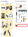
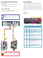
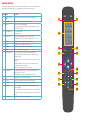
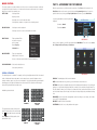
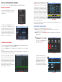
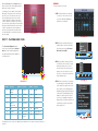
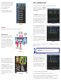
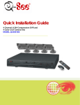
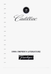
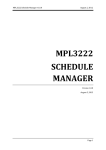
Quick Installation
Guide
For Bundles Featuring the QC444
H.264 Network DVR
QC444-403/411/426
4 Channel H.264 Compression DVR with
Variable CIF and D1 Recording Options
PART 1 - PACKAGE CONTENTS
PART 2 - DVR CAMERA AND POWER CONNECTIONS
4 Color Cameras with Stands
(403 & 411)
QC444 DVR
2 Color Cameras with Stands
2 Decoy Cameras (426)
Manual and
Software CD
STEP 1: Connect the Cameras
to the Cables
1A Connect both camera leads to the matching
ends on the power/video cable.
Repeat for all cameras.
1B
manuals and
software
QC Series
Attach the BNC connector on the power/video cable to a
Video In port on the DVR. Repeat for all cameras.
1C
Pre-Installed
Hard Drive
Connect the remaining
connector to one of the
ends on the power
splitter. Repeat for all
cameras.
Ethernet
Cable
2 BNC(M) to RCA(F)
Adapters
STEP 2:
Connect the single end
of the power splitter to
the included power supply.
AUDIO OUT
2
4
2
1
3
1
DC 12V
VGA
VIDEO OUT
STEP 3:
Connect the other power supply to the DVR .
STEP 5:
Connect thesurge protector
to an outlet.
Power Supply & 4-Way Splitter
(403 & 411)
Power Supply
for DVR
STEP 4:
Video and Power
Camera Cable
2-Way Splitter
(426)
Connect both power supplies to
a surge protector.
IMPORTANT! It is STRONGLY recommended to use a surge protector that
is UL-1449 rated. Look for a clamping voltage of 330 or lower, a Joule rating
of at least 400 and a response time of 10 nanoseconds or less.
USB 2.0
Mouse
The appearance
of contents may
differ from images
shown.
Remote
Control
Revised
5/18/11
PART 3 - CONNECTING THE DVR TO YOUR DISPLAY
PART 4 - DVR CONTROLS
To Connect to a TV:
This DVR can be controlled through the USB mouse, the remote control or by using the buttons on
the front panel of the device. We have found that the majority of our customers prefer to operate
their DVRs using the USB mouse because of its ease of use and flexibility and our manual is set up
with this in mind. The remote control allows you to perform most of the day-to-day functions from a
convenient distance. It functions as a typical remote control with additional buttons allowing you to
navigate through menus and control functions. We recommend that you configure your DVR using
the mouse controls, reserving the remote control for operations such as live viewing, file search and
playback.
1.
2.
Plug the BNC to RCA adapter in to Video Out port then connect the RCA cable
(not included) to the DVR.
Connect the other end of the RCA cable to the Video Input on the TV.
To Connect to a Computer Monitor:
3.
4.
Plug the VGA cable (not included) to the VGA port on the DVR.
Connect the other end of the VGA cable to the monitor.
FRONT PANEL
NOTE! You may use both a video monitor and a television
simultaneously with this DVR.
1
2
3
4
5
6
AUDIO OUT
2
4
2
1
3
1
DC 12V
VGA
7
8
VIDEO OUT
1
2
3
4
Number
Item
Function
1
Function
Button
Single Channel Viewing Mode: Opens Color Adjustment
2
IR Sensor
Infrared Receiver for Remote Control
3
Escape Button Exit any menu or current operation
4
Enter Button
5
Directional
Buttons
6
Power Button
Virtual Keyboard: Backspace function
Viewing Mode: Go To Menu
In Menu: Acts as mouse click
Navigate through menus.
Change selections in pull down menus (Up/Down buttons)
Toggle settings (Up/Down buttons)
Puts DVR into Standby mode or wakes it up.
Alarm: Not functional on this model
7
Status Lights
Net: Red light indicates that network connection is lost
HDD: Red light indicates that hard drive is operating
Power: Red light indicates that DVR is powered up
8
IMPORTANT! The default resolution of this DVR is 1024x768 pixels. Some
monitors smaller than 19” may have problems displaying this resolution.
USB Port
For use with flash drive when backing up or updating
firmware. Not for use with mouse.
REMOTE CONTROL
The buttons on the Remote Control operate in the same manner as on a conventional DVR remote.
Some buttons have multiple functions depending on which menu is being accessed.
Num
Name
Function
1
Multiple-window
switch
Switch between multiple-window and one-window view
2
0-9 number key
Input password, channel or switch channel.
3
Record
Start or stop recording manually
1
Enter /Menu key
5
Direction keys
Go to default button
Go to the menu
2
Switch current activated control, go to left or right.
Add
.,
ABC
DEF
GHI
JKL
MNO
4
5
6
PQRS
TUV
WXYZ
7
8
9
0
-/--
1
In record interface, working with the direction buttons to select
the channel to record
4
Mult
2
9
3
In playback mode, it is to control the playback process bar.
6
Previous
In playback mode, playback the previous video.
7
Next
In playback mode, playback the next video.
8
Slow Play
Multiple slow play speeds or normal playback.
9
Address
Click to input device serial number
10
Function/Aux Key
In 1-channel monitor mode: pop up assistant function
In motion detection interface, functions as a directional key to
complete setup
3
4
Record
Fn
Enter/Menu
Esc
10
11
Backspace: Press for 1.5 seconds to clear all contents in current
text box.
In HDD information interface, used to switch between HDD
record time and other information
5
Special combined operation in some menus.
11
Escape/Cancel
Go back to previous menu or cancel current operation (close
upper interface or control)
In playback mode, it goes to real-time monitor mode.
12
Stop
In playback mode, stop current playback.
13
Forward
Various forward speeds and normal speed playback.
14
Backward
Various backward speeds and normal speed playback.
15
Play/Pause
Reverse playback or paused mode, click this button to realize
normal playback.
In normal playback click this button to pause or resume playback.
In real-time monitor mode, click this button to enter video search
menu.
16
Fast Forward
Various fast speeds and normal playback.
6
12
13
7
14
8
DVR
15
16
MOUSE CONTROL
The mouse operates in a manner similar to how it is used on a conventional computer; point-andclick, right-click, double click and so on. How these functions are used is based on the context of
where they are used. Some examples are:
LEFT CLICK:
Selecting an item
Opening a menu
Checking a box or motion detection status
Selecting letters, numbers or symbols on the virtual keyboard.
Selecting an event for playback
Selecting a screen to zoom into from multi-screen mode
Exits any window. Exits
any menu or reopens
previous menu.
Opens Pop-Up
Shortcut Menu
When the system boots up, it will be in multi-screen mode. Press Enter on the front panel, the
Enter/Menu button on the remote control to bring up the System Login window. You can also
right-click the mouse to bring up the Pop-Up Shortcut menu where you select Main Menu.
Log in using the Admin account using the virtual
keyboard.
DOUBLE CLICK:
RIGHT CLICK
PART 5 - ACCESSING THE DVR’S MENUS
SYSTEM LOGIN
Username: admin
User Name
Password: admin
Password
OK
View 1
View 4
4 5 6
7 8 Cancel
9
0
PICTURE 5-1
Color Setting
Once you have logged in, you will be presented with the Main Menu. There are 6 icons; Search,
Info, Setting, Advanced, Backup and Shutdown.
Search
Record
Main Menu
Page up or page down
Switch items in check box
Increase or decrease numerical value in numerical input box
CLICK-AND-DRAG
Select motion detection zone
Select privacy mask zone
VIRTUAL KEYBOARD
The virtual keyboard is contextual. For example, it will only show digits when the field is for numeral
entries. In fields where letters and symbols can be entered, users can switch between various
formats – numbers, upper case, lower case and symbols – by selecting the white keyboard symbol
that will appear to the right of a field where text can be entered. The symbol itself will change to
show which keyboard format is available next.
1 2 3
4 5 6
7 8 9
0
a
h
o
u
b
i
p
v
NUMBERS
The keyboards are used by clicking on the
desired character. Spaces are entered using
the
symbol and characters are deleted
with the
key. Clicking outside of the
keyboard will close it.
123
1 2 3
MOUSE WHEEL
Available keyboards include:
admin
1/ 2: 3. A
4? 5- 6_ H
7 @ 8 # 9% O
0&
U
SYMBOLS
c
j
q
w
d
k
r
x
e
l
s
y
f g
m n
t
z
UPPER CASE
LETTERS
B
I
P
V
C
J
Q
W
D
K
R
X
E
L
S
Y
LOWER CASE
LETTERS
PICTURE 5-2
SEARCH: Find and playback files from the hard drive.
INFO: Contains hard drive info, system log, version information, and online users.
SETTING: Most system configuration takes place in this window and its submenus. Access General
settings to set system time, language, hard drive overwrite, file size, and video display format. The
Encode submenu is where you set compression, frame rate, bit rate, audio, and sub stream. You will
also find chedule setup, network setup, motion detection setup, display setup, and default settings
here.
ADVANCED: Used for hard drive management, manual recording, account setup, auto maintenance, and TV output adjustment.
BACKUP: Backup files from the hard drive.
SHUTDOWN: Use this icon to safely shut down the system.
F G
MN
T
Z
PART 6 - SETTING DVR TO RECORD
There are two modes for recording: Manual Recording and Scheduled Recording.
MANUAL RECORDING
You can get to the Manual Record menu by right
clicking on the screen with the mouse and selecting Record.
View 1
View 4
Color Setting
Search
Record
Main Menu
This will take you to the Record menu. You can
click the All option on the Manual row to start
recording on all channels, or you can select only
the cameras that you want to begin recording.
To stop recording, select the Stop option under
each camera to cause that camera to cease recording, or you can selecting the All option in the
Stop row to cause all cameras to stop.
PICTURE 6-1
An example of such a mixed schedule is shown
in Picture 6-4. In this example, Camera 1 is
scheduled to record if motion is detected (MD)
from midnight to 8am and then records continuously from 8am to noon (Regular) followed by a
one-hour motion detection recording segment
until 1pm before returning to continuous recording after that. Then, at the end of the day, it is in
motion detection mode from 5pm to midnight.
The scale running along the bottom of the menu
ranges from 0 to 24, representing the hours of
a day. You can set starting and ending times to
any specific minute you choose.
SCHEDULE
Channel
1
PreRecord 4
sec.
Week Day Wed
Period 1 00 :00
Record Type Regular MD
Period 2
08 :00
-12 :00
Period 3
12 :00
-13 :00
Period 4
13 :00
-17 :00
Period 5
17 :00
-24 :00
Period 6
00 :00
-24 :00
MD
Regular
0
3
Copy
Alarm MD/Alarm
-08 :00
6
Alarm
9
Paste
12
15
Default
MD/Alarm
18
Save
21
24
Cancel
PICTURE 6-4
Please note that this DVR does not support external alarms. Schedule settings utilizing Alarm recording will not produce any recordings.
MOTION DETECTION RECORDING
There are three steps to scheduling the DVR to record on motion.
STEP 1. Return to the Record menu (Picture 6-2) and designate which cameras will be
recording in Motion Detection mode.
STEP 2. Next, go to the Schedule (Picture 6-3) menu as described above and set schedule
for each camera.
PICTURE 6-2
SCHEDULED RECORDING
STEP 3. After setting up the schedule go to
the Main Menu and select the Setting
menu. Inside, select the Detect window
(Red square in Picture 6-5)
To record on a schedule you will need to get to the Record menu as described above and select the
cameras on the Schedule row instead of the Manual row.
Next, go to the Main Menu, and click on Settings, and select Schedule. This will open the Schedule menu.
The DVR is programmed with all cameras set to record constantly by default. You may set up your
own schedule to meet your specific requirements.
There are six blocks of time you can use to
schedule recording and each camera can be
individually configured or they all may share the
same schedule. In addition, you may set up individual schedules for each day, or you may share
the same schedule across every day.
Cameras may be scheduled to record in different
modes at different times of the day.
PICTURE 6-5
The Detect window will allow you to
configure your camera and the actions
the DVR will perform when motion is
detected. Under Event Type select
Motion Detect, Select your Channel,
or All, and select the enable option to
enable the camera for motion detection.
PICTURE 6-3
DETECT
Event Type
Motion Detect
Channel
1
Enable
Region
Select
Sensitivity
3
Period
Set
Anti-dither
0
Show Message
Alarm upload
Record Channel 1 2 3 4
Delay
10
Tour
1 2 3 4
Snapshot
1 2 3 4
Buzzer
Copy
Paste
sec.
Send Email
sec.
Default
PICTURE
6-7
PICTURE 6-6
Save
Cancel
Next under Region click the Select button to
set up the area of the camera display that you
want to be sensitive to motion.
SEARCH
To begin a search for an event:
You will then see the camera’s view overlaid
with a grid. The green box is the current location of the cursor. The red area is the sensitive area and the black area is not sensitive
to motion. Click the Fn button on the remote
control to adjust the sensitivity of your mouse
as you move the cursor. After you have finished
the setup click the Enter button on the remote
control to exit. Next set your sensitivity level
from 1 to 6 (6 being the most sensitive), then
click the Save button on the Detect screen to
save the setting.
STEP 1. Enter the date to be searched.
You can also click on the clock icon
to open the Calendar. Highlighted
dates have recorded files.
PICTURE 6-7
PICTURE 7-2
PART 7 - PLAYING BACK FILES
1
The Search and Playback window
can be accessed through the Shortcut
menu. You can view the playback from
any camera that was activate during the
recording session.
2
1p
2p
3p
4p
StartTime Type
11:37:22 M
11:48:00 R
11:54:00 A
12:10:00 M
13:00:00 R
14:00:00 R
15:00:00 R
16:00:00 R
17:00:00 R
All
Alarm
MD
Alarm/MD
STEP 2. Enter the start time (if known) or
skip this field to search the entire day.
Select the type of event; All, Alarm, or
Motion Detection (MD).
All
CH
1
PICTURE 7-3
3
4
5
08-19-2010 00: 00: 00
7
Start Time
08-19-10 13:20:00
6
End Time
08-19-10 13:26:00
All
CH
1
2
3
4
15
13
Size(KB) 52736
14 16
ALL
9 11
8 10 12
17 19 21
18 20
PICTURE 7-1
Number
Function
Number
1
Playback
Window
8
Function
Reverse
Number
15
Function
Backup
2
File List
9
Fast Play
16
Search
3
File Information
10
Previous
Frame
17
Next Channel
4
Playback
Progress Bar
11
Next Frame
18
Next File
5
Stop
12
Volume
19
Video Clip
6
Slow Play
13
Previous File
20
Repeat Playback
7
Play
14
Previous
Channel
21
Full Screen
The playback screen can be set to display the recordings from one camera or as many channels as
you have.
STEP 3. Select which channels you wish
to view. Each of the four slots is a pulldown which allows you to select a
specific channel. You can leave these
empty to view 1-3 channels. You can
also choose to view all four channels at
a time simultaneously.
STEP 4. Click on the Search icon and any
records fitting your criteria will be listed
in the column to the right of the screen.
Up to 128 files can be displayed and
multiple tabs (pages) may be displayed
in the search results depending on the
number of cameras you have as well
as how you configured your playback
display. In the event that a camera is set
to manually record, the events will be
broken up by hour.
CH
13
11:37:22 M
14
11:48:00 R
15
11:54:00 A
16
112:10:00
2 M3
13:00:00 R
PICTURE 7-4
14:00:00
R
15:00:00 R
16:00:00 R
17:00:00 R
Start Time
08-19-10 15:00:00
End Time
08-19-10 15:59:00
Size(KB) 52736
PICTURE 7-5
4
PART 8 - BACKING UP FILES
Files will be listed by their start time. In addition,
when the DVR records a file, it also indicates
the type of recording and it will indicate this
one-letter code after the file name.
1p
2p
3p
4p
The DVR supports backing up to USB flash drives, hard drives, burners, and SD cards.
StartTime Type
11:37:22 M
11:48:00 R
11:54:00 A
12:10:00 M
13:00:00 R
14:00:00 R
15:00:00 R
16:00:00
R
PICTURE 7-6
17:00:00 R
R = Regular recording
A = External alarm triggered recording
M = Motion detection triggered recording
Plug in a USB device and go to the Main Menu
and then clicking on the Backup icon will open
the Backup window.
The Backup window will display any connected
devices along with available space and status.
If you have a device connected to the USB port
on the side of the DVR and it does not appear,
press the Detect button. If it still does not
appear, then use a different USB device.
PICTURE 7-9
PLAYBACK
Once you’ve run your search, you may select which videos you wish to review.
Start, Stop and Play
Double-click on the desired video file and
playback will begin. The playback controls
operate as with a normal DVD player or
computer media player with pause, rewind,
etc. In the case of multiple views, the channel
with the green outline around its video is the
one that is being controlled. You can switch
between channels by clicking on the one you
wish to control.
Stop
Fast Next
Play Frame
Playback
Slider
Once an external USB device is detected,
pressing the Backup button will open a new
window allowing you to select which files to
back up. You can select by channel, start and
end times, as well as which type of event;
regular recording, alarm, motion detection or all
of them.
Only files with a check mark in front of them will
be backed up. You can deselect whichever files
you choose or select them all by selecting the
box at the top of the list.
PICTURE 7-10
If you need to clear space on your external drive, you can use the Erase button. This will delete
ALL files on that device.
Volume
Play Slow
Play
Reverse Previous
Frame
IMPORTANT! USB hard drives must be formatted as FAT 32.
PICTURE 7-7
1p
While all channels will display video from the
same event, individual playbacks can be
controlled separately. A single channel can be
paused, rewound or sped up without affecting
the playback of other channels.
Selecting the Stop button will end playback of
that channel while the others (if any) continue
to play back. To end playback on all channels,
simply right-click the mouse or move to
another file using the buttons to the right of the
playback bar.
2p
3p
4p
StartTime Type
11:37:22 M
11:48:00 R
11:54:00 A
12:10:00 M
13:00:00 R
14:00:00 R
15:00:00 R
16:00:00 R
17:00:00 R
Once you have selected the files, press Start
to begin the download. A progress bar will be
displayed showing estimated time remaining.
During the download, the Start button will
change to Stop. You can stop the process at
any time by pressing the button again.
You can also right-click out of the menu once
the file transfer has begun to go on to other
activities without cancelling the download.
Start Time
08-19-10 13:20:00
PICTURE 7-11
End Time
08-19-10 13:26:00
Size(KB) 52736
08-19-2010 00: 00: 00
All
CH
1
2
3
4
ALL
PICTURE 7-8
The files will be saved with the following naming format:
SN_CH(channel number)_TYPE_TIME(Year, Month, Date, Hour, Minute, Second)
Therefore, a file shown on the DVR as being a regular record (R), being recorded on 01/04/11
starting at 2:00:00 would have a file name of: 1_01_R_010411020000.dav
The files can be played back using the software included on the CD accompanying this DVR.
QUESTIONS OR COMMENTS? CONTACT US
Q-See Products
Digital Peripheral Solutions, Inc.
PRODUCT SUPPORT, DOWNLOADS,
FIRMWARE UPDATES
& MANUALS
8015 E. Crystal Drive
www.Q-See.com
MAILING ADDRESS
Anaheim, CA 92807
CUSTOMER SUPPORT
FAX
714-998-3509
WEBSITE
www.Q-See.com
Live Chat at www.Q-See.com (M-F, 9-5 PST)
Email: [email protected]
Phone: 877-998-3440 (M-F, 9-5 PST)