1
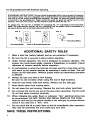
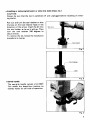
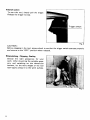
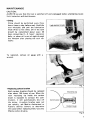
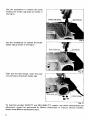
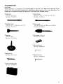
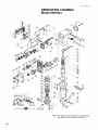
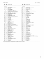
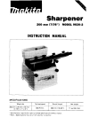
Demolition Hammer
MODEL HM1301
INSTRUCTION MANUAL
SPEC1F ICATIONS
Blows per minute
1,200
I
Overall length
Net weight
6 4 3 mm (25-5/16")
16.3 kg ( 3 6 Ibs)
IMPORTANT
SAFETY INSTRUCTIONS
(For All Tools)
WARNING: WHEN USING ELECTRIC TOOLS,
BASIC SAFETY PRECAUTIONS SHOULD ALWAYS BE FOLLOWED TO
REDUCE THE RISK OF FIRE, ELECTRIC SHOCK, AND PERSONAL INJURY, INCLUDING THE FOLLOWING:
READ ALL INSTRUCTIONS.
1. KEEP WORK AREA CLEAN. Cluttered areas and benches invite injuries.
2. CONSIDER WORK AREA ENVIRONMENT. Don't use power tools in damp
3.
4.
5.
6.
7.
8.
9.
IO.
11.
12.
13.
2
or wet locations. Keep work area well lit. Don't expose power tools t o rain.
Don't use tool in presence of flammable liquids or gases.
KEEP CHILDREN AWAY. All visitors should be kept away from work area.
Don't let visitors contact tool or extension cord.
STORE IDLE TOOLS. When not in use, tools should be stored in dry, and
high or locked-up place - out of reach of children.
DON'T FORCE TOOL. It will do the job better and safer at the rate for which
it was intended.
USE RIGHT TOOL. Don't force small tool or attachment to do the job of
a heavyiduty tool. Don't use tool for purpose not intended.
DRESS PROPERLY. Don't wear loose clothing or jewelry. They can be caught
in moving parts. Rubber gloves and non-skid footwear are recommended
when working outdoors. Wear protective hair covering t o contain long hair.
USE SAFETY GLASSES. Also use face or dust mask if cutting operation
is dusty.
DON'T ABUSE CORD. Never carry tool by cord or yank it t o disconnect from
receptacle. Keep cord from heat, oil, and sharp edges.
SECURE WORK. Use clamps or a vise t o hold work. It's safer than using
your hand and it frees both hands t o operate tool.
DON'T OVERREACH. Keep proper footing and balance at all times.
MAINTAIN TOOLS WITH CARE. Keep tools sharp and clean for better and
safer performance. Follow instructions for lubricating and changing accessories. Inspect tool cords periodically and if damaged, have repaired by
authorized service facility. Inspect extension cords periodically and replace
if damaged. Keep handles dry, clean, and free from oil and grease.
DISCONNECT TOOLS. When not in use, before servicing, and when changing accessories, such as blades, bits, cutters.
14. REMOVE ADJUSTING KEYS AND WRENCHES. Form habit of checking to
15.
16.
17.
18.
19.
20.
21.
see that keys and adjusting wrenches are removed from tool before turning it on,
AVOID UNINTENTIONAL STARTING. Don't carry plugged-in tool with finger
on switch. Be sure switch is OFF when plugging in.
OUTDOOR USE EXTENSION CORDS. When tool is used outdoors, use only
extension cords intended for use outdoors and so marked.
STAY ALERT. Watch what you are doing, use common sense. Don't operate tool when you are tired.
CHECK DAMAGED PARTS. Before further use of the tool, a guard or other
part that is damaged should be carefully checked t o determine that it will
operate properly and perform its intended function. Check for alignment
of moving parts, binding of moving parts, breakage of parts, mounting, and
any other conditions that may affect its operation. A guard or other part
that is damaged should be properly repaired or replaced by an authorized
service center unless otherwise indicated elsewhere in this instruction manual. Have defective switches replaced by authorized service center. Don't
use tool if switch does not turn it on and off.
GUARD AGAINST ELECTRIC SHOCK. Prevent body contact with grounded
surfaces. For example; pipes, radiators, ranges, refrigerator enclosures.
PROPER GROUNDING. This tool should be grounded while in use t o protect the operator from electric shock.
EXTENSION CORDS: Use only three-wire extension cords which have threeprong grounding-type plugs and three-pole receptacles which accept the
tool's plug. Replace or repair damaged or worn cord immediately.
VOLTAGE WARNING: Before connecting the tool t o a power source (receptacle,
outlet, etc.) be sure the voltage supplied is the same as that specified on the
nameplate of the tool. A power source with voltage greater than that specified
for the tool can result in SERIOUS INJURY t o the user - as well as damage t o
the tool. If in doubt, DO NOT PLUG IN THE TOOL. Using a power source with
voltage less than the nameplate rating is harmful t o the motor.
3
For all grounded tools with American type plug.
GROUNDING INSTRUCTIONS: Thistool should be grounded while i n use t o protect the operator
from electric shock. The tool i s equipped with a threetonductor cord and three-prong groundingtype plug to fit the proper grounding-type receptacle. The green (or green and yellow) conductor
in the cord i s the grounding wire. Never connect the green (or green and yellow) wire t o a live
terminal. Your unit is for use on 115 volts and has a plug that looks like Fig. " A .
An adapter Fig. "B' and "C" i s available for connecting Fig. "A" type plugs t o two-prong receptacles. The green-colored rigid ear, lug, etc., extending from the adapter must be connected t o a
permanent ground, such as a properly grounded outlet box.
Grounding Blade
Cover of Grounded Outlet Box
ADDITIONAL SAFETY RULES
1. Wear a hard hat (safety helmet) and an ear protector if necessary.
2. Be sure the bit is secured in place before operation.
3. Under normal operation, the tool is designed t o produce vibration. The
screws can come loose easily, causing a breakdown or accident. Check
tightness of screws carefully before operation.
4. In cold weather or when the tool has not been used for a long time, let the
tool warm up for several minutes by operating it under no load. This will
loosen up the lubrication. Without proper warm-up hammering operation
is difficult.
5. Always be sure you have a firm footing.
Be sure no one is below when using the tool in high locations.
6. Hold the tool firmly with both hands. Always use the side grip.
7. Keep hands away from moving parts.
8 . Do not leave the tool running. Operate the tool only when hand-held.
9. Do not point the tool at any one in the area when operating. The bit could
fly out and injure someone seriously.
IO. When chipping into walls, floors or wherever "live" electrical wires may
be encountered, DO NOT TOUCH ANY METAL PARTS OF THE TOOL!
Hold the tool only by the plastic handle or the side grip t o prevent electric
shock if you chip into a "live" wire.
11. Do not touch the bit or parts close t o the bit immediately after operation;
they may be extremely hot and could burn your skin.
SAVE THESE INSTRUCTIONS.
4
I
0
Installing or removing'hull point or other bits (cold chisel, etc.)
CAUTION :
Always be sure that the tool i s switched off and unplugged before installing or removing the bit.
Pull out and turn the tool retainer so that
the boss on the tool retainer faces in the
direction of the arrow. Insert the bit into
the tool holder as far as it will go. Then
turn the tool retainer 180 degrees to
secure the bit.
To remove the bit, follow the installation
procedure in reverse.
Fig. 1
Fig.
0
:
Swivel handle
The easy-grip handle swivels a full 360".
This makes the demolition hammer extremely handy for all kinds of operation.
I
Fig. 3
5
Switch action
To start the tool, simply pull the trigger.
Release the trigger to stop.
Trigger switch
Fig. 1
CAUTION :
Before plugging in the tool, always check to see that the trigger switch actuates properly
and returns to the “OFF” position when released.
-
Demolishing . Chipping Scaling
Choose the right accessories for your
work. After mounting the suitable accessory and switching on the demolition
hammer, l e t the mere weight of the tool
itself apply pressure to the work surface.
Fig. 5
6
MAINTENANCE
CAUTION :
ALWAYS be sure that the tool is switched off and unplugged before attempting to perform inspection and maintenance.
e Oiling
Oiling should be performed every three
hours (once a day before use). Hold the
tool vertically and pull the lubrication
knob three to five times. Oil in the tank
should be replenished about every 20
days, presuming 3 - 4 hours’ operation
daily, or when oil is out of sight through
the window after placing the tool vertically.
Fig. 6
To replenish, remove oil gauge with a
wrench.
0
Replacing carbon brushes
Both carbon brushes should be replaced
after about 150 hours of use. When the
resin insulating tip inside the carbon
brush i s exposed to contact the commutator, it will automatically shut off
the motor. If carbon brushes wear out
too quickly, ask Makita Authorized or
Factory Service Centers to determine
the cause before replacing them. Use only
Makita carbon brushes.
Insulating tip
>f--
Fig. 8
7
Use the screwdriver to remove the screw
holding the holder cap plate as shown in
the figure.
Fig. 9
Use the screwdriver to remove the brush
holder cap as shown in the figure.
Take out the worn brush, insert the new
one and secure the brush holder cap.
Fig. 1
To maintain product SAFETY and RELIABILITY, repairs, any other maintenance and
adjustment should be performed by Makita Authorized or Factory Service Centers,
always using Makita replacement parts.
8
ACCESSORIES
CAUTION :
These accessories or attachments are recommended for use with your Makita tool-specified in this
manual. The use of any other accessories or attachments might present a risk of injury t o persons. The
accessories or attachments should be used only in the proper and intended manner.
Bull point
410 mm (16-118”)
Part No. 751407-0
Cold chisel
36 mm (1-318”) x 4 1 0 mm (16-118“)
Part No. 751207-8
Scaling chisel
100 mm ( 4 “ ) x 310 mm (12-114”)
Part No. 751211-7
Clay spade
1 2 0 mm (4-314“) x 500 mm (19.518”)
Part No. 751 604-8
Rammer
200 mm (8”)
Par? No. 751 702-8
Oil supply (100 cc)
Part No. 181118-7
Hex wrench 5
Part No. 783203-8
Wrench 23
Part No. 781012-9
Hex wrench 6
Part No. 783204-6
Steel carrying case
Part No. 18 1805-8
9
July-16-'84
US
DEMOLITION HAMMER
Model HM1301
Note: The switch and other part configurations
may differ from country to country.
10
MODEL HM1301
Nov-09-'84
SDDESCRIPTION
"0"
2
3
4
5
6
7
8
9
10
11
12
13
14
15
16
19
20
21
22
23
24
25
26
27
28
29
30
31
32
33
34
35
36
37
38
39
40
41
42
43
44
45
46
47
48
49
50
51
52
53
2
2
I
1
1
1
1
1
1
4
4
4
1
1
1
1
1
1
1
1
1
1
1
1
1
2
3
2
1
1
2
2
1
1
1
1
1
4
4
4
1
1
I
1
1
1
4
4
2
1
1
-
DESCRIPTION
MACHINE
MACHINE
~
~
1
At,
US
Hex Socket Head Bolt M6x16
Spring Washer 6
Rear Cover
Motor Housing
CORD ASSEMBLY
IAssembled Cord Plug & Item 61
Cord Guard
Pan Head Screw M 4 ~ 1 8(With Washer1
Strain Relief
Pan Head Screw M4x8 (With Washerl
Hex Socket Head Bolt M6x30
Spring Washer 6
Flat Washer 6
Handle Set (With Item 191
Switch
Pan Head Screw M4x16 IWith Washerl
D",t
Cover
Handle Set IWith Item 131
0 Ring 3 5
Screw Sea1
Ball Bearing 6202LLB
Dust Seal 15
Fan 92
ARMATURE ASSEMBLY
(Wrth Item 22 - 271
Dust Seal 10
Ball Bearing 620oL18
Hex Bolt M5x15 IWith Washer1
Pan Head Screw M5x25 IWith Washerl
Insul8tmn Washer
011Seal 3 0
Gear Housing
Spring Washer 6
Hex Socket Head Bolt M6x25
Pin 6
Ball Bearing 6201118
Helical Gear 43
B ~ I Bearing
I
6201~~8
Gear Housing Cover
Spring Washer 6
Hex Socket Head Bolt M6x60
Rivet 0 - 5
Name Plate
Ball Bearing 6302LLB
Helical Gear 68
Ring
25
Ball Bearing 6205110
Bearing BOX
Spring Washer 6
Hex Socket Head Bolt M6x 18
Woodruff key 4
Crank Shaft
011 Gauae
54
55
56
57
58
59
60
61
6
1
1
1
1
1
2
1
1
1
62
63
64
65
66
67
68
69
70
71
72
73
74
75
76
77
78
79
80
81
02
83
84
6
6
1
1
1
I
1
1
1
1
1
1
1
4
4
1
1
1
2
2
2
2
85
86
87
88
89
90
91
92
93
94
95
96
97
98
99
IO0
101
1
1
1
1
1
1
1
1
1
1
1
1
1
4
2
2
2
2
102
103
I04
105
I06
__
1
1
1
-
Hex 0011 M5x14 (With Washer)
011Tank Cover
081 Tank Packing
Compression Spring 4
Steel Ball 4 8
Plunger
Pan Head Screw M4x14 IWith Washer)
Tool Retainer
Steel Ball 7 9
Compression Spring 5
Hex Socket Head Boll Max30
Spring Washer 8
Tool Holder
Urethane Ring 44
0 Ring 24
0 Ring 24
Seal Holder
0 Ring 65
Idler
Rubber Ring 68
Flat Washer 60
Nylon Rmg 60
Cylinder Packing
Spring Washer 8
Hex Socket Head Bolt Max35
Cylinder
Side Handle
Plafe
Her Socket Head Bolt Max25
Spring Washer 8
Hex U Nul Max13
Split Pin 4 - 25
Grip 30
Hammer
Piston Ring 46
Inner Ring 42
Piston Ring 46
Inner Ring 42
P1StO"
Pl" 1 0
Connecting Rod
Needle Bearing 1716
Crank Sleeve
Spring Washer 10
Hex Socket Head Bolt M10x35
Countersunk Head Screw M4x10 (With Washerl
Holder Cap Plate
Cap Rubber
Holder Cap
Carbon Brush
FIELD ASSEMBLY
Rubber Pin 4
Rubber Pin 4
Note The switch and other part Specifications may differ from Country Io country
11
MAKITA LIMITEDONE YEAR WARRANTY
Warranty Policy
Every Makita tool is thoroughly inspected and tested before leaving the factory. It is warranted to
be free of defects from workmanship and materials for the period of ONE YEAR from the date of
original purchase. Should any trouble develop during this one-year period, return the COMPLETE
tool, freight prepaid, to one of Makita’s Factory or Authorized Service Centers. If inspection shows
the trouble is caused by defective workmanship or material, Makita will repair (or at our option,
replace) without charge.
This Warranty does not apply where:
repairs have been made or attempted by others:
repairs are required because of normal wear and tear:
The tool has been abused, misused or improperly maintained;
alterations have been made to the tool.
IN NO EVENT SHALL MAKITA BE LIABLE FOR ANY INDIRECT, INCIDENTAL OR CONSEQUENTIAL DAMAGES FROM THE SALE OR USE OF THE PRODUCT. THIS DISCLAIMER
APPLIES BOTH DURING AND AFTER THE TERM OF THIS WARRANTY.
MAKITA DISCLAIMS LIABILITY FOR ANY IMPLIED WARRANTII:S, INCLUDING IMPLIED
WARRANTIFS 01 “MERCHANTABILITY” AND ‘WTNESS FOR A SPFClFlC PURPOSE,”
AFTER THE ONE-YEAR TERM OF THIS WARRANTY.
This Warranty gives you specific legal rights, and you may also have other rights which vary from
state to state. Some states do not allow the exclusion or Limitation of incidental or consequential
damages, so the above limitation or exclusion may not apply to you. Some states do not allow
Makita Corporation
3-11-8, Sumiyoshi-cho,
Anjo, Aichi 446 Japan
883445A067
PRINTED IN JAPAN
1991 - 11 - N