1
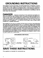
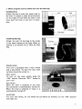
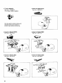
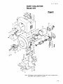
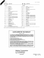
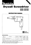
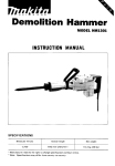
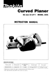
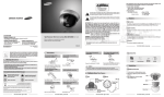
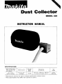
Dust Collector
MODEL 410
INSTRUCTION MANUAL
SPECIFICAT I0NS
Peak air flow when
hose and dust bag
are installed
8.7 mJ/min.
1307 cu. ft./min.)
1
1
No load
Sealed suction l d; ; ; ;
510 mm (20")
of water
,o,ooo
1
Dimensions
IL
Hj
287 mm x 285 mm x 280 mm
( 1 1-114''
x 11.114" x 11")
~
* Manufacturer reserves t h e right t o change specifications w i t h o u t notice
* Note: Specifications may differ f r o m country t o country.
1
Net
weight
9.3 kg
120.4Ibs)
IMPORTANT
SAFETY INSTRUCTIONS
Wh n sing an electrical appliance, basic precaution sha rld
always be followed, including the following:
READ ALL INSTRUCTIONS
BEFORE USING THIS APPLIANCE
WARNING-TO
reduce the risk of fire, electric shock, or
injury:
1. Do not leave appliance when plugged in. Unplug from outlet when not in
use and before servicing.
2. Electric shock could occur if used on wet surfaces. Do not expose to rain.
Store indoors.
3. Do not allow to be used as a toy. Close attention is necessary when used
by or near children.
4. Use only as described in this manual. Use only manufacturer's recommended attachments.
5. Do not use with damaged cord or plug. If appliance is not working as it
should, has been dropped, damaged, left outdoors, or dropped into water,
return it to a service center.
6. Do not pull or carry by cord, use cord as a handle, close a door on cord,
or pull cord around sharp edges or corners. Do not run appliance over cord.
Keep cord away from heated surfaces.
7. Do not unplug by pulling on cord. To unplug, grasp the plug, not the cord.
8. Do not handle plug or appliance with wet hands.
9. Do not put any object into openings. Do not use with any opening blocked;
keep free of dust, lint, hair, and anything that may reduce air flow.
10. Keep hair, loose clothing, fingers, and all parts of body away from openings
and moving parts.
11. This tool is for collecting dust or shavings exhausted from wood shop tools.
Do not attempt to cdlect wood chips, metal, rocks, string, liquids or the like.
12. Do not pick up anything that is burning or smoking, such as cigarettes,
matches, or hot ashes.
13. Turn off all controls before unplugging.
2
14. Use extra care when cleaning on stairs.
15. Do not use t o pick up flammable or combustible liquids such as gasoline
or use in areas where they may be present.
16. EXTENSION CORDS: Use only three-wire extension cords which have threeprong grounding-type plugs and three-pole receptacles which accept the
tool's plug. Replace or repair damaged or worn cord immediately.
17. OUTDOOR USE EXTENSION CORDS. When tool is used outdoors, use only
extension cords intended for use outdoors and so marked.
18. Connect to a properly grounded outlet only. See Grounding Instructions.
19. AVOID UNINTENTIONAL STARTING. Be sure switch is OFF when plugging in.
20. GUARD AGAINST ELECTRIC SHOCK. Prevent body contact with grounded
surfaces. For example; pipes, radiators, ranges, refrigerator enclosures.
VOLTAGE WARNING: Before connecting the tool to a power source (receptacle,
outlet, etc.) be sure the voltage supplied is the same as that specified on the
nameplate of the tool. A power source with voltage greater than that specified
for the tool can result in SERIOUS INJURY to the user - as well as damage t o
the tool. If in doubt, DO NOT PLUG IN THE TOOL. Using a power source with
voltage less than the nameplate rating is harmful to the motor.
ADDITIONAL SAFETY RULES
1. Always use protective goggles, a cap and mask when using as a blower.
2. Never point the nozzle at anyone in the vicinity when using as a blower.
3. Do not block cooling vents. These vents permit cooling of the motor. Blockage should be carefully avoided lest the motor burn out from lack of ventilation.
4. Do not fold, tug nor step on the hose.
5. Always switch off and wait for the fan to come to a complete stop before
installing or removing the hose.
6. Never stick your hands into the inlet or outlet.
3
GROUNDING INSTRUCTIONS
This appliance must be grounded. If it should malfunction or breakdown, grounding provides a path of least resistance for electric current to reduce the risk of
electric shock. This appliance is equipped with a cord having an equipmentgrounding conductor and grounding plug. The plug must be plugged into an appropriate outlet that is properly installed and grounded in accordance with all
local codes and ordinances.
DANGER
- Improper connection of the equipment-grounding conductor can result in a risk of electric shock. The green (or green and yellow) conductor in the cord is the grounding wire. Never connect the grounding wire to
a live terminal. Check with a qualified electrician or service person i f you are in
doubt as to whether the outlet is properly grounded. Do not modify the plug
provided with the appliance - if it will not fit the outlet, have a proper outlet
installed by a qualified electrician.
This appliance is for use on a nominal 115-volt circuit, and has a grounding plug
that looks like the plug illustrated in Fig. A. A temporary adapter that looks like
the adapter illustrated in Fig. B and C may be used to connect this plug to a 2-pole
receptacle as shown in Fig. B if a properly grounded outtet is not available. The
temporary adapter should be used only until a properly grounded outlet (Fig. A)
can be installed by a qualified electrician. The green colored rigid ear, lug, or the
like extending from the adapter must be connected to a permanent ground such
as a properly grounded outlet box cover. Whenever the adapter is used, it must
be held in place by a metal screw.
GROUNDING METHODS
TAB FOR
GROUNDED
OUTLET BOX
GROUNDED SCREW
GROUNDING’
PIN
Fig. A
QMV
L
I I ILQL IIYQ
Fig. B
I
nu-
This appliance is intended for commercial use.
4
Fig. C
I IWIYQ.
1. When using this tool to collect dust into the dust bag
Installing hose
Attach the end of hose (the metal end) to
the inlet. To attach it, align the protrusions
on the inside of hose with the slots in the
inlet, push the hose in and turn it clockwise.
Switch action
This tool is equipped with a main switch
and a sub-switch. To start the tool, both
switches should be turned on.
Main switch:
To turn on the main switch, press the
"ON" button. Press the "OFF" button to
turn it off.
Sub-switch:
When the hose i s attached to the inlet,
the sub-switch is automatically turned on.
When the hose is removed or loose, it is
automatically turned off.
CAUTION :
For your own safety, do not defeat the sub-switch by holding it in the "ON" position
with tape, etc.
5
Overload protector
The overload protector automatically cuts out to break the circuit whenever heavy work
is prolonged. If this occurs, first turn off the main switch and unplug the tool. Then detach the hose and the inlet from the tool and remove the foreign matter clogging the fan.
Now attach the inlet and the hose and press the restart button.
CAUTION :
Before pressing the restart button, always be sure to wait 20 seconds after the tool
stopped.
Operation
Avoid using the tool with the end of hose buried in a pile of dust, or the tool may become clogged.
Emptying dust bag
Inspect the insides of the dust bag through
the window.
When the dust bag is about 213 (two thirds)
full, turn off the main switch and remove
the dust bag from the tool. Unzip the
fastener and empty the dust bag of i t s
contents, tapping it lightly so as to remove
particles adhering to the insides.
CAUTION :
Empty the dust bag of its contents before
the dust bag is full, or the tool may become clogged.
6
2. When exhausting dust from indoors to outdoors
Installing hoses
Attach one hose to the inlet and another
hose to the outlet in the same manner as
mentioned in page. 5.
CAUTION :
The total length of exhaust hose and suction hose should be less than 10 meters
(32 feet). Otherwise the tool may become
cIogged.
”
MAINTENANCE
CAUTION :
Always be sure that the tool i s switched’off and unplugged before attempting to perform
inspection or maintenance.
The tool will stop when the carbon brushes wear to a certain length. When this occurs,
both carbon brushes should be replaced.
To maintain product SAFETY and RELlABl LITY, reparis, maintenance or adjustment
including brush inspection and replacement should be performed by Makita Authorized
or Factory Service Centers, always using Makita replacement parts.
7
ACCESSORIES
CAUTION :
These accessories or attachments are recommended for use with your Makita tool specified in this
manual. The use of any other accessories or attachments might present a risk of injury to persons. The
accessories or attachments should be used only in the proper and intended manner.
When using this tool as blower
Nozzle 81Cover
Part No. 191716-9
Installing cover and nozzle
Attach the cover to the inlet and the hose
to the outlet in the same manner as mentioned in page 5.
Attach the nozzle to the hose.
CAUTION :
Never let anything to get into the inlet during blower operation.
8
If you connect this dust collector to a Makita planer or planer-jointer, you can perform
clean, dust-free operation. To do so, use shaving hoods.
CAUTION:
.When dust or shavings exhausted from the planer or planer-jointer are large or wet,
run the planer or the planer-jointer under light load. Otherwise the tools may become
clogged.
.The total length of exhaust hose and
suction hose should be tess than the max.
length shown in the Table right. Otherwise the tools may become clogged.
Table
Max, length of hoses
For Model
2004
20 m ( 6 6 feet)
2030
2.5 m (8.2 feet)
2040
.These shaving hoods are for planing operation. You cannot use them for jointing operation.
Dust bag
Part No. 166023-9
0
Floor nozzle assembly
Part No. 122361-9
0
Flexible hose
2m
Part No.
2.5 m Part No.
5m
Part No.
1 0 m Part No.
191779-5
191711-9 ( w i t h metal end)
191712-7
191713-5
Hose joint
Part No. 191757-5
Can be used t o collect chips
and sawdust o n floor.
0
Joint 100 assemMy
Part No. 122336-8
Clamp 90
Part No. 191715-1
Can be connected w i t h other
hood makes ( l o o @ )
9
0
Y-joint assembly
Part No. 122342-3
(For Model 2030, 2030N)
0
Hood for Model 2012
Part No. 192010-2
Can be used t o collect chips and
sawdust from auto-planer or
jointer feed side by switching.
0
Hood for Model 2030N
Part No. 191 71 9-3
0
Hood for Model 2004
Part No. 191717-7
0
Hood for Model 2040
Part No. 191721-6
0
Hood for Model 2030
Part No. 191720-8
10
Oct -31-85
EN
DUST COLLECTOR
Model 410
Note: The switch, noise suppressor and other part configurations
may differ from country to country.
11
July-17-'86
$.D
O"', M
DESCRIPTION
O
',:'M
US
,& DESCRIPTION
MACHINE
~
1
1
Name Plafe
2
2
2
2
1
1
1
1
Rivet
3
4
5
6
7
'8
9
10
11
12
13
14
15
16
17
18
19
20
21
22
23
24
25
26
27
28
29
4
1
1
1
2
2
1
1
6
4
2
1
1
1
1
1
1
1
1
1
1
Hex Nut M12
Washer 12
Switch Protector
Relay Cover
Cowling
Inlet
Pan Head Screw M4x6 IWifh Washeri
Torsion Spring 10
Hex Nut M12
Switch Holder
Pan Head Screw M4x6 lWiih Washeri
Pan Head Screw M4x6 IWith Washerl
Switch Guard
Switch
Pan Head Screw M4xB IWilh Washer1
Pan Head Screw M5x70 IWnh Washeri
Pan Head Screw M4xB lWith Washeri
Bracket A
Ball Bearing 6202LLB
Motor Cover
FIELD ASSEMBLY
Fan 106
End Bell
Ball Bearing 6200LLB
50
51
52
53
54
57
58
59
Dust Seal 10
ARMATURE ASSEMBLY
Item 21 22 27
33
34
35
36
37
38
40
41
42
43
44
45
46
47
48
49
55
56
Dust Seal 1 5
IWith
30
31
32
0-5
~
291
4
4
Hex Nut M 5
Spring Washer 5
4
Pan Head Screw M4x6 [With Warheri
60
61
62
63
64
65
4
1
1
1
1
1
1
1
1
1
1
1
Mount
Over Current Relay KM 152
Relay Holder
Hex Nut M12
Switch
Pan Head Screw M4x6 IWith Washeri
Sponge Sheet
Scroll
Seal
Fan 130
Lock Washer 12
Hex Nu1 M10
Switch Cover
1
Grommet
3
2
1
1
1
3
2
1
4
4
1
1
1
2
1
2
2
2
Pan
Pan
Pan
Pan
2
Head Screw
Head Screw
Head Screw
Head Screw
Strain Relief
Pan Head Screw
M4x6 (With Warheri
M4x6 IWith Washed
M4xB (With Warheri
M 5 x l 2 IWith Warheri
M4x6 (With Warheri
Grommet
Bare
Pan Head Screw M4x16 (With Washeri
Cushion
Cord Guard
Cord
Strain Relief
Pan Head Screw M 5 x l 2 (With Washer1
Band
Pan Head Screw M4x10 (With Washer)
Brush Holder
Carbon Brush
Note The SWmh and other part specifccationS m a y differ f r o m country to country
MAKITA LIMED O N E YEAR WARRANTY
Warranty Policy
Every Makita tool is t h o r o u L l y inspected and tested before leaving the factory. It is warranted to
be free of defects from wor-hanship and materials for the period of ONE YEAR from the date of
original purchase. Should any trouble develop dunng this one-year period, retum the COMPLETE
tool, frelBht prepaid. to one of Makita's FactoN or Authorized Service Centers. If tnmectmn shows
the trouble h caused by defective workmanship or material, Makita will repail, (or i t our option,
replace) without charge.
This Warranty does not apply where:
repairs have been made or attempted by others:
repairs are required because of normal wear and tear:
The tool has been abused, misused or improperly maintained;
alterations have been made to the tool.
IN NO EVENT SHALL MAKITA BE LIABLE FOR ANY INDIRECT, INCIDENTAL OR CONSEQUENTIAL DAMAGES FROM THE SALE OR USE O F THE PRODUCT. THIS DISCLAIMER
APPLIES BOTH DURING AND AFTER THE TERM O F THIS WARRANTY.
MAKITA DISCLAIMS LIABILITY FOR ANY IMPLIED WARRANTIES, INCLUDING IMPLIED
WARRANTIES O F "MERCHANTABILITY" AND "FITNESS FOR A SPECIFIC PURPOSE,"
AFTER THE ONE-YEAR TERM O F THIS WARRANTY.
This Warranty gives you specific legal rights, and you may also have other nghts which vary from
state to state. Some States d o not allow the exclusion or limitation of incidental or consequential
damages, so the above limitation or exclusion may not apply to you. Some states d o not allow
limitation on how long an implied warranty lasts, so the above limitation may not apply to you.
Makita Corporation
3-11-8, Sumiyoshi-cho,
Anjo, Aichi 446 Japan
883487A061
PRINTED IN JAPAN
1991 - 6 - N