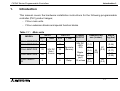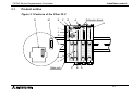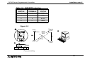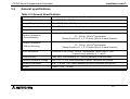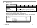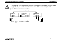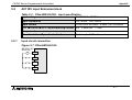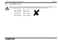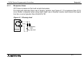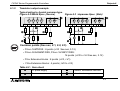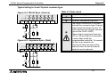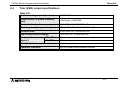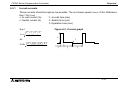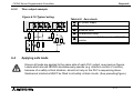
1
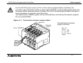
DSS/DS HARDWARE MANUAL FX2NC (DSS/DS) SERIES PROGRAMMABLE CONTROLLERS FX2NC Series Programmable Controllers Foreword • This manual contains text, diagrams and explanations which will guide the reader in the correct installation and operation of the FX2NC and should be read and understood before attempting to install or use the unit. • If in doubt at any stage during the installation of the FX2NC always consult a professional electrical engineer who is qualified and trained to the local and national standards. If in doubt about the operation or use of the FX2NC please consult the nearest Mitsubishi Electric distributor. • This manual is subject to change without notice. FX2NC Series Programmable Controllers FX2NC (DSS/DS) Series Programmable Controllers Manual number : JY992D76401 Hardware Manual Manual revision : D Date : DEC. 2000 i FX2NC Series Programmable Controllers Guidelines for the safety of the user and protection of the FX2NC. This manual provides information for the installation and use of the FX2NC. The manual has been written to be used by trained and competent personnel. The definition of such a person or persons is as follows; a) Any engineer who is responsible for the planning, design and construction of automatic equipment using the product associated with this manual should be of a competent nature, (trained and qualified to the local and national standards required to fulfill that role). These engineers should be fully aware of all aspects of safety with regards to automated equipment. b) Any commissioning or service engineer must be of a competent nature, trained and qualified to the local and national standards required to fulfill that job. These engineers should also be trained in the use and maintenance of the completed product. This includes being completely familiar with all associated documentation for the said product. All maintenance should be carried out in accordance with established safety practices. c) All operators of the completed product should be trained to use that product in a safe and co-ordinated manner in compliance to established safety practices. The operators should also be familiar with documentation which is connected with the actual operation of the completed equipment. Note : The term ‘completed equipment’ refers to a third party constructed device which contains or uses the product associated with this manual. ii FX2NC Series Programmable Controllers Note’s on the symbols used in this manual At various times through out this manual certain symbols will be used to highlight points which are intended to ensure the users personal safety and protect the integrity of the equipment. Whenever any of the following symbols are encountered, its associated note must be read and understood. Each of the symbols used will now be listed with a brief description of its meaning. Hardware warnings 1) Indicates that the identified danger WILL cause physical and property damage. 2) Indicates that the identified danger could POSSIBLY cause physical and property damage. 3) Indicates a point of further interest or further explanation. Software warning 4) Indicates special care must be taken when using this element of software. 5) Indicates a special point which the user of the associate software element should be aware of. 6) Indicates a point of interest or further explanation. iii FX2NC Series Programmable Controllers MEMO iv FX2NC Series Programmable Controllers Contents. 1. Introduction .........................................................................................1-1 1.1 1.2 1.3 1.4 1.5 Unit accessories............................................................................................. 1-10 World Spec. ................................................................................................... 1-10 Model name ................................................................................................... 1-11 Serial numbers .............................................................................................. 1-12 Configuration.................................................................................................. 1-13 1.5.1 1.5.2 1.5.3 1.5.4 1.5.5 Summary ........................................................................................................... 1-15 Current consumption and input/output points.................................................... 1-17 Rules ................................................................................................................. 1-21 System configuration example .......................................................................... 1-24 Quick judgment ................................................................................................. 1-27 2. Terminal layouts..................................................................................2-1 2.1 2.2 2.3 Main units......................................................................................................... 2-1 FX2NC Extension blocks ................................................................................. 2-3 FX2N and FX0N Extension blocks ................................................................... 2-4 3. Installation notes .................................................................................3-1 3.1 3.2 3.3 3.4 3.5 3.6 3.7 3.8 3.9 3.10 Product outline ................................................................................................. 3-2 FX2NC RUN/STOP Control .............................................................................. 3-4 General specifications...................................................................................... 3-6 PLC mounting arrangements ........................................................................... 3-7 Connection of extension blocks to main unit.................................................... 3-9 DIN rail mounting ............................................................................................. 3-9 Direct mounting ............................................................................................. 3-10 Extension cable installation............................................................................ 3-12 General notes ................................................................................................ 3-13 Memory Board installation ............................................................................. 3-14 v FX2NC Series Programmable Controllers 3.11 3.12 3.13 3.14 3.15 Contents. Wiring techniques .......................................................................................... 3-15 Termination of connector style I/O ................................................................. 3-16 Termination of Terminal style I/O................................................................... 3-16 Termination of screw terminals ...................................................................... 3-19 Termination of connector style I/O cables...................................................... 3-20 4. Power supply.......................................................................................4-1 4.1 4.2 Power supply cautions ..................................................................................... 4-4 Earthing / Grounding........................................................................................ 4-6 5. Inputs ..................................................................................................5-1 5.1 24V DC input specifications ............................................................................. 5-1 5.1.1 5.1.2 5.1.3 5.1.4 5.2 Typical wiring....................................................................................................... 5-2 Input circuit connection........................................................................................ 5-4 Diodes and inputs connected in series;............................................................... 5-5 Resistors and inputs connected in parallel;......................................................... 5-6 AC110V input Extension block......................................................................... 5-7 5.2.1 5.2.2 Input circuit connection........................................................................................ 5-7 Programming caution .......................................................................................... 5-8 6. Outputs ...............................................................................................6-1 6.1 Transistor output specification ......................................................................... 6-1 6.1.1 6.1.2 6.2 Response times................................................................................................... 6-2 Transistor output example ................................................................................. 6-3 Relay output specification ................................................................................ 6-5 6.2.1 6.2.2 Reliability tests .................................................................................................... 6-6 Relay output example.......................................................................................... 6-7 vi FX2NC Series Programmable Controllers 6.3 Triac (SSR) output specifications..................................................................... 6-9 6.3.1 6.3.2 6.4 Contents. In-rush currents ................................................................................................. 6-10 Triac output example......................................................................................... 6-11 Applying safe loads........................................................................................ 6-11 7. Diagnostics..........................................................................................7-1 7.1 7.2 Preliminary checks........................................................................................... 7-1 Basic diagnostics ............................................................................................. 7-2 7.2.1 7.2.2 7.2.3 7.3 7.4 7.5 7.6 7.7 7.8 7.9 BATT LED ON..................................................................................................... 7-2 ERROR LED flashes (PROGRAM ERROR) ....................................................... 7-2 ERROR LED ON (CPU ERROR) ........................................................................ 7-3 Common errors ................................................................................................ 7-4 Replacing the battery ....................................................................................... 7-4 Maintenance .................................................................................................... 7-4 Error flags ON indicates error. ......................................................................... 7-5 Error registers .................................................................................................. 7-7 Error codes ...................................................................................................... 7-9 Instruction list ................................................................................................. 7-10 vii FX2NC Series Programmable Controllers Contents. viii FX2NC Series Programmable Controllers 1 INTRODUCTION 2 TERMINAL LAYOUTS 3 INSTALLATION NOTES 4 POWER SUPPLY 5 INPUTS 6 OUTPUTS 7 DIAGNOSTICS Introduction 1. FX2NC Series Programmable Controllers Introduction 1. FX2NC Series Programmable Controllers 1. Introduction 1. Introduction This manual covers the hardware installation instructions for the following programmable controller (PLC) product ranges; - FX2NC main units. - FX2NC extension blocks and special function blocks Table 1.1 : Main units MODEL INPUT QTY TYPE OUTPUT QTY FX2NC-16MT-DSS 8 8 FX2NC-32MT-DSS 16 16 FX2NC-64MT-DSS 32 FX2NC-96MT-DSS 48 FX2NC-16MR-TDS 8 24V DC Sink / Source 32 TYPE Transistor (Source) 48 8 Relay POWER SUPPLY 24V DC +20% -15% DIMENSIONS mm (inches) MASS kg (lbs) 0.2 (0.44) 35 (1.4) 60 (2.4) Ripple 86 Voltage (3.4) (p-p) 5% or less 35 (1.4) 90 (3.5) 87 (3.4) 0.35 (0.77) 0.45 (0.99) 89 (3.5) 1-1 FX2NC Series Programmable Controllers Introduction 1. Figure 1.1 :Main unit dimensions UNITS: mm (inches) FX2NC-96M 86(3.39) FX2NC-64M 60(2.36) FX2NC-32M FX2NC-16MT 35(1.38) Y0 Y1 Y2 Y3 Y4 Y5 Y6 Y7 Y10 Y11 Y12 Y13 Y14 Y15 Y16 Y17 X0 1 2 RUN STOP FX2NC-16MR-T Y0 1 2 Y0 Y1 Y2 7 Y3 6 7 COM1 5 6 X0 5 X1 Y4 X2 3 X4 X3 3 COM STOP 13 (0.5) DIN Rail: 35mm (1.38) 15 (0.6) 13 (0.5) Power supply cable Power supply cable DIN Rail:35mm (1.38) 89(3.50) 74(2.91) 74(2.91) 87(3.43) 13 (0.51) COM X7 X6 X5 X4 X0 X1 X2 X3 X4 X5 X6 X7 X10 X11 X12 X13 X14 X15 X16 X17 35(1.38) POWER RUN BATT ERROR RUN 90(3.54) 90(3.54) POWER RUN BATT ERROR FX2NC-16MR-T 1-2 FX2NC Series Programmable Controllers Introduction 1. Table 1.2 : Extension blocks MODEL FX2NC-16EX-DS FX2NC-16EYT-DSS FX2NC-32EX-DS FX2NC-32EYT-DSS FX2NC-16EX-T-DS FX2NC-16EYR-T-DS INPUT OUTPUT DIMENSIONS mm (inches) QTY TYPE QTY DEVICE TYPE 16 24V DC Sink/ Source - - - - - 16 Transistor Source 32 24V DC Sink/ Source - - - - - 32 Transistor Source 16 24V DC Sink/ Source - - - 20.2 (0.8) - - 16 Relay - 24.2 (0.95) MASS kg (lbs) 0.15 (0.33) 14.6 (0.6) 87 (3.4) 26.2 (1.0) 0.2 (0.44) 90 (3.5) 89 (3.5) 0.2 (0.44) 1-3 FX2NC Series Programmable Controllers Introduction 1. Table 1.2 : Extension blocks MODEL INPUT OUTPUT QTY TYPE QTY DEVICE TYPE FX0N-8EX-UA1/UL 8 110V AC inputs - - - FX0N-8EX-ES/UL 8 - - - FX0N-8ER-ES/UL 4 24V DC Sink/ Source 4 FX0N-8EYR-ES/UL - - 8 FX0N-8EYT-ESS/UL - - 8 Transistor Source 16 24V DC Sink/ Source - - - FX0N-16EX-ES/UL Relay - - - 16 Relay - FX0N-16EYT-ESS/UL - - 16 Transistor Source 16 24V DC Sink/ Source - - - FX2N-16EYR-ES/UL - - 16 Relay - FX2N-16EYT-ESS/UL - - 16 Transistor Source MASS kg (lbs) 43 (1.7) - FX0N-16EYR-ES/UL FX2N-16EX-ES/UL DIMENSIONS mm (inches) 0.2 (0.44) 90 (3.5) 87 (3.4) 70 (2.8) 40 (1.6) 0.3 (0.66) 90 (3.5) 87 (3.4) 1-4 0.3 (0.66) FX2NC Series Programmable Controllers Introduction 1. Table 1.3 : Connector conversion adapter MODEL FX2NC-CNV-IF DESCRIPTION Extension blocks and special functions blocks of FX2N and FX0N are connected by this adapter DIMENSIONS mm (inches) 14.6 (0.6) 90 (3.5) MASS kg (lbs) 74 (2.9) 1-5 0.15 (0.33) FX2NC Series Programmable Controllers Introduction 1. Figure 1.2 :Extension block dimensions UNITS: mm (inches) FX2NC-32E 26.2(1.03) FX2NC-16E 14.6(0.57) FX2NC-16EYR-T 24.2(0.95) FX2NC-16EX-T 20.2(0.80) FX2NC-16EX-T X0 X1 X2 X3 X4 X5 X6 X7 COM X0 X1 X2 DIN Rail: 35mm (1.38) 74(2.91) 15 (0.6) DIN Rail: 35mm (1.38) 89(3.50) 74(2.91) 87(3.43) 13 (0.51) COM X7 X6 X5 X4 X0 1 2 3 X4 5 6 7 X0 1 2 3 X4 5 6 7 X3 PW X0 X1 X2 X3 X4 X5 X6 X7 X0 X1 X2 X3 X4 X5 X6 X7 90(3.54) 90(3.54) POWER FX0N, FX2N Extension block dimensions →(See sec. 3.7) 1-6 FX2NC Series Programmable Controllers Introduction 1. Figure 1.3 :Connector conversion adapter 90(3.54) UNITS: mm (inches) 14.6(0.57) 74(2.91) DIN Rail: 35mm (1.38) 1-7 FX2NC Series Programmable Controllers Introduction 1. Table 1.4 :Special function blocks NUMBER OF I/O MODEL POWER SUPPLY DESCRIPTION I O Internal External 5V DC 24V DC FX2N-2DA Digital to analog converter - 8 - 30mA 85mA*1 FX2N-2AD Analog to digital converter - 8 - 20mA 50mA*1 FX2N-2LC Temperature control - 8 - 70mA 55mA FX2N-4DA Digital to analog converter - 8 - 30mA 200mA FX2N-4AD Analog to digital converter - 8 - 30mA 55mA FX2N-8AD Analog to digital converter - 8 - 50mA 80mA FX2N-4AD-PT PT 100 probe interface - 8 - 30mA 50mA FX2N-4AD-TC Thermo-couple interface - 8 - 30mA 50mA FX2N-1HC High speed counter - 8 - 90mA - FX2N-1PG Pulse output, Position control - 8 - 55mA 40mA FX2N-232IF RS232 Interface block - 8 - 40mA 80mA FX2N-32CCL CC-Link Interface block - 8 - 130mA 50mA MELSEC-I/O LINK FX2N-16LNK-M Remote I/O system master block *2 8 *2 200mA 90mA DIMENSIONS mm (inches) 43 (1.7) 55 (2.1) 75 (3.0) 55 (2.1) kg (lbs) 0.2(0.44) 87 (3.4) 0.3(0.66) 75 0.4(0.88) (3.0) 90 55 (3.5) (2.1) 43 (1.7) MASS 0.3(0.66) 0.2(0.44) 87 (3.4) 0.3(0.66) 0.2(0.44) 43 (1.7) 0.5(1.1) 1-8 FX2NC Series Programmable Controllers Introduction 1. Table 1.4 :Special function blocks NUMBER OF I/O MODEL POWER SUPPLY DESCRIPTION I FX0N-3A Analog / Digital converter FX0N-16NT Net-mini interface FX0N-32NT-DP Profibus DP Interface FX2N-10GM - O 8 8 8 Internal External 5V DC 24V DC 30mA 90mA*1 20mA 60mA FX2N-1RM-ESET Programmable cam switch MASS kg (lbs) 0.2(0.44) 43 (1.7) - 8 - 170mA 20mA - 8 - - 5W 60 (2.4) - 8 - - 10W 86 (3.4) 0.4(0.88) - 8 - - 210mA 55 111 97 (2.1) (4.4) (3.8) 0.5(1.1) Positioning controller FX2N-20GM DIMENSIONS mm (inches) 90 87 0.3(0.66) (3.5) (3.4) 0.3(0.66) *1 : Internal 24V DC *2 : The value depends on the switch setting. 1-9 FX2NC Series Programmable Controllers 1.1 Introduction 1. Unit accessories MPU-Main unit : FX2NC-100MPCB power supply cables. Extension block : I / O label kit. 1.2 World Spec. Table 1.5 : World / Japanese Spec. Input Sink / Source World spec models : SINK / SOURCE. Japanese models : ALWAYS SINK. Outputs Transistor World spec models : ALWAYS SOURCE. Japanese models : ALWAYS SINK. 1-10 FX2NC Series Programmable Controllers 1.3 Introduction 1. Model name F X 2 N C - 1 6 M T- ¨ - D S S / ¨ A) B) C) G) F) E) D) Table 1.6 : Model table A) PLC type : FX2NC, FX2N, FX0N B) Total number of I / O channels E) Omit AC, Japanese spec. M MPU - main unit E D Powered extension unit EX Extension block, input DS F) EY Extension block, output R Relay S Triac (SSR) T Transistor 24V DC Japanese spec. 24V DC World spec. DSS 24V DC World spec., DC source transistor ES Output type D) Terminal style I/O. ,Only FX2NC. Features Unit type C) T ESS AC Power Supply World spec.,DC sink transistor AC Power Supply World spec., DC source transistor UA1 AC Power Supply, AC inputs G) UL CE,UL registered product 1-11 FX2NC Series Programmable Controllers 1.4 Introduction 1. Serial numbers S E R I A L N O. : 9 X 3 2 6 7 3) 1) e.g. 9=1999 0=2000 2) 1-9 X Y Z = Jan - Sept = Oct = Nov = Dec Table 1.7 : Notes on serial numbers 1) Production year 2) Production month 3) Production serial number 1-12 FX2NC Series Programmable Controllers 1.5 Introduction 1. Configuration Figure 1.4 :Schematic system FX0N-232ADP FX0N-485ADP F FX2NC-EEPROM-16 FX2NC-RTC FX2NC-EEPROM-4C FX2NC-EEPROM16C 1 2 FX2NC-16MT-DSS 5 FX2NC-32MT-DSS FX2NC-64MT-DSS FX2NC-96MT-DSS FX2NC-16MR-T-DS G 3 4 FX2NC-16EX-DS FX2NC-16EYT-DSS FX2NC-32EX-DS FX2NC-32EYT-DSS FX2NC-16EX-T-DS FX2NC-16EYR-T-DS 6 A B FX2NC-CNV-IF FX2N-16EX-ES/UL FX2N-16EYR-ES/UL FX2N-16EYT-ESS/UL FX0N-8EX-ES/UL FX0N-8EX-UA1/UL FX0N-8ER-ES/UL FX0N-8EYR-ES/UL FX0N-8EYT-ESS/UL FX0N-16EX-ES/UL FX0N-16EYR-ES/UL FX0N-16EYT-ESS/UL D C RS 422/RS 232 CONVERTER FX-232AW(C) J FX-16E-TB/UL FX-32E-TB/UL FX-16EYR-ES-TB/UL FX-16EYS-ES-TB/UL FX-16EYT-ESS-TB/UL FX-16EYT-ES-TB/UL MELSEC MEDOC FX-PCS/AT-EE L MELSEC MEDOC PLUS FX-PCS/WIN-E K FX-10P-E FX-20P-E A6 GPP/PHP + FX-A6GPP-E-KIT I FX-10DU-E FX-20DU-E FX-25DU-E FX-30DU-E FX-40DU-ES FX-40DU-TK -ES FX-50DU-TKS-E F930GOT F940GOT H FX2N-2DA FX2N-4DA FX2N-2AD FX2N-4AD FX2N-4AD-PT FX2N-4AD-TC FX2N-2LC FX2N-8AD FX2N-1HC FX2N-1PG FX2N-232IF FX2N-32CCL FX2N-16LNK-M FX0N-3A FX0N-16NT FX0N-32NT-DP FX2N-1RM-E-SET FX2N-10GM FX2N-20GM E 1-13 FX2NC Series Programmable Controllers Introduction 1. Table 1.8 : Configuration notes A MPU-Main unit (Main Processing Unit) B Extension block C Connector conversion adapter D Extension block E Special function block F Function adapters G Memory board (Real time clock) H Data access units I Dedicated programming J Computer interface K Computer software L Terminal block • Left hand side port ‚ Memory port ƒ Programming port „ I/O port … MPU bus port † Unit bus port 1-14 FX2NC Series Programmable Controllers 1.5.1 Introduction 1. Summary Connection of FX2NC series extension blocks only The FX2NC series input extension blocks and FX2NC series output extension blocks can be directly connected to the FX2NC series main unit. These input/output extension blocks can be connected in the desired order. After connection, octal numbers will be assigned to the input/ output points of the extension blocks. These octal numbers are regarded as the input/output numbers. The smallest number will be assigned to the input/output point next to the main unit, and then sequentially increased for the subsequent input/output points. Before connection, calculate the number of connectable input/output points by referring to Sec. 1.5.3, or quickly obtain this number using the table shown in Sec. 1.5.5. X020 X060 X100 - - - - X 0 0 0 -X 0 1 7 X040 X037 X057 X077 X117 F X 2N C -3 2 M T-D S S X : 1 6 p o in ts Y : 1 6 p o in ts Y 0 0 0 -Y 0 1 7 16EX 16EX 16EYT 16EX 16EYT 16EYT 16EX 16EYT 1 6 p o in ts 1 6 p o in ts 1 6 p o in ts 1 6 p o in ts 1 6 p o in ts 1 6 p o in ts 1 6 p o in ts 1 6 p o in ts Y020 Y040 Y060 Y100 - - - - Y037 Y057 Y077 Y117 1-15 FX2NC Series Programmable Controllers Introduction 1. Connection of FX0N and FX2N series extension blocks and function adapter To connect an FX2NC series main unit to FX0N or FX2N series extension blocks, be sure to connect an FX2NC-CNV-IF connector conversion adapter first. Following the adapter, up to 4 blocks can be connected. In addition, one special adapter can be connected to the left side of the base unit. Before connection, calculate the number of connectable input/output points by referring to Sec. 1.5.3. F X 0N -2 3 2 A D P (F u n ctio n a d a p te r) F X 2N C -3 2 M T -D S S F X 2N C S e rie s e xte n s io n b lo ck s F X 2N C -C N V -IF (C o n n e cto r co n ve rsio n a d a p te r) F X 2N -1 6 E Y R -E S /U L re la y o u tp u t b lo ck F X 2N -2 3 2 IF R S -2 3 2 C b lo c k F X 2N -1 P G p u ls e o u tp u t b lo ck F X 2N -4 A D a n a lo g b lo ck 4 b lo ck s, m a xim u m 1-16 FX2NC Series Programmable Controllers 1.5.2 Introduction 1. Current consumption and input/output points The following tables show current consumption and input/output points of various types of FX2NC series main units, extension blocks, and special function blocks. While referring to Sec. 1.5.3, calculate the total current consumption and input/output values using the following main unit values (values Œ through •), extension block values, and special function block values. Table 1.9 : Base units MODEL Œ CURRENT CAPACITY • INPUT Ž OUTPUT FX2NC-16MT-DSS FX2NC-16MR-T-DS 600mA 8 8 16 FX2NC-32MT-DSS 560mA 16 16 32 FX2NC-64MT-DSS 480mA 32 32 64 FX2NC-96MT-DSS 400mA 48 48 96 5V DC X Y • TOTAL 1-17 FX2NC Series Programmable Controllers Introduction 1. . Table 1.10: Extension blocks CURRENT CONSUMPTION 5V DC INPUT X OUTPUT Y TOTAL FX2NC-16EX-DS 30mA 16 - 16 FX2NC-16EX-T-DS 30mA 16 - 16 FX2NC-16EYT-DSS 50mA - 16 16 FX2NC-16EYR-T-DS 50mA - 16 16 FX2NC-32EX-DS 60mA 32 - 32 FX2NC-32EYT-DSS 100mA - 32 32 FX0N-8ER-ES/UL 25mA 4(8) 4(8) 16*1 FX0N-8EX-ES/UL 25mA 8 - 8 FX0N-8EX-UA1/UL 25mA 8 - 8 FX0N-8EYR-ES/UL 30mA - 8 8 FX0N-8EYT-ESS/UL 30mA - 8 8 FX0N-16EX-ES/UL 40mA 16 - 16 FX0N-16EYT-ESS/UL 40mA - 16 16 FX0N-16EYR-ES/UL 40mA - 16 16 FX2N-16EX-ES/UL 45mA 16 - 16 FX2N-16EYR-ES/UL 40mA - 16 16 FX2N-16EYT-ESS/UL 180mA - 16 16 MODEL *1:8 points are used for actual input/output, however, this block should occupy 16 input/output points. 1-18 FX2NC Series Programmable Controllers Table 1.11: Special function block Introduction 1. Function adapters CURRENT CONSUMPTION 5V DC INPUT X TOTAL X/Y OUTPUT Y FX0N-3A 30mA - 8 - 8 FX0N-16NT 20mA 8 - 8 16 FX0N-32NT-DP 170mA - 8 - 8 FX2N-2AD 20mA - 8 - 8 FX2N-4AD 30mA - 8 - 8 FX2N-8AD 50mA - 8 - 8 FX2N-4AD-PT 30mA - 8 - 8 FX2N-4AD-TC 30mA - 8 - 8 FX2N-2DA 30mA - 8 - 8 FX2N-4DA 30mA - 8 - 8 FX2N-2LC 70mA - 8 - 8 FX2N-1HC 90mA - 8 - 8 FX2N-1PG 55mA - 8 - 8 FX2N-232IF 40mA - 8 - 8 FX2N-32CCL 130mA - 8 - 8 MODEL 1-19 FX2NC Series Programmable Controllers Introduction 1. CURRENT CONSUMPTION 5V DC INPUT X TOTAL X/Y OUTPUT Y 200mA *2 8 *2 *2 FX2N-10GM - - 8 - 8 FX2N-20GM - - 8 - 8 FX2N-1RM-ESET *3 - - 8 - 8 FX0N-232ADP 200mA - - - - FX0N-485ADP 30mA - - - - FX-2PIF 290mA - - - - MODEL FX2N-16LNK-M *2:Value depends on the switch setting. *3:Maximum of 1 unit can be connected. 1-20 FX2NC Series Programmable Controllers 1.5.3 Introduction 1. Rules 1) Add the input/output points of the extension blocks and special functions blocks to the input/ output points of the main unit. The total number of input and output points should be no more than 256 points. However, the total number of input points should be 184 points or less, and the total number of output points should also be 184 points or less. 2) The FX2NC series main unit supplies control power (5V DC) to the extension blocks and special function blocks. For this reason, the total current consumption of all the blocks connected to the main unit should not exceed the current capacity of the main unit. 3) Next to the FX2NC-CNV-IF, up to 4 blocks can be connected. To connect a special function unit, such as the FX-10GM or FX2N-1RM-E-SET, refer to the instruction manual of the corresponding special function block. Calculation form for system configuration Enter current consumption values and input/output points of the extension blocks and special function blocks while referring to Sec. 1.5.2, and then calculate the total current value • and total input and output points ‘ through ”. From the obtained values, judge whether the blocks can be connected. 1-21 FX2NC Series Programmable Controllers Introduction 1. Table 1.12 : Calculation form Block Model FX2NC series FX2NC-16EX-DS input FX2NC-16EX-T-DS extension FX2NC-32EX-DS block Current Number of consublocks mption connected Current consumption × number of blocks INPUT X OUTPUT Y X/Y 30 mA blocks mA points points 60 mA blocks mA points points 50 mA blocks mA points points 100 mA blocks mA points points FX0N/FX2N series extension block (4 blocks, maximum) mA blocks mA points points points mA blocks mA points points points mA blocks mA points points points mA blocks mA points points points Function adapter mA blocks mA - mA blocks mA - FX2NC series FX2NC-16EYT-DSS output FX2NC-16EYR-T-DS extension FX2NC-32EYT-DSS block 2-port interface FX-2PIF ‘ Total input points: • Total current ’ Total output points: consumption: “ Total input/output common points: mA ” Total points: 1-22 points points points points FX2NC Series Programmable Controllers Introduction 1. Judgment form a) 5V DC control current capacity check 5 V D C c u rre n t ca p a c ity o f m a in u n it (va lu e Œ s h o w n in S e c. 1 .5 .2 ): mA ≥ To ta l cu rre n t co n s u m p tio n o f a ll c o n n e c te d b lo c ks (va lu e • w ritte n in c a lcu la tio n fo rm ): mA b) Input/output point connection upper limit check In p u t p o in t c o n n e c tio n u p p e r lim it : 1 8 4 p o in ts O u tp u t p o in t c o n n e c tio n u p p e r lim it: 1 8 4 p o in ts In p u t/o u tp u t p o in t c o n n e c tio n u p p e r lim it: 2 5 6 p o in ts ≥ In p u t p o in ts o f m a in u n it (va lu e • s h o w n in S e c . 1 .5 .2 ): p o in ts ≥ O u tp u t p o in ts o f m a in u n it (va lu e Ž s h o w n in S e c . 1 .5 .2 ): p o in ts ≥ In p u t/o u tp u t p o in ts o f m a in u n it (va lu e • s h o w n in S e c . 1 .5 .2 ): p o in ts + To ta l in p u t p o in ts o f a ll c o n n e c te d b lo ck s (va lu e ‘ w ritte n in c a lc u la tio n fo rm ): p o in ts = p o in ts + To ta l o u tp u t p o in ts o f a ll c o n n e c te d b lo ck s (va lu e ’ w ritte n in c a lc u la tio n fo rm ): p o in ts = p o in ts + To ta l in p u t/o u tp u t p o in ts o f a ll c o n n e c te d b lo ck s (va lu e ” w ritte n in c a lc u la tio n fo rm ): p o in ts = p o in ts If all the above conditions are met, the extension and special function blocks can be connected to the base block. If one of the above conditions is not met, reduce the number of input/output points or number of blocks, or change the types of blocks to be connected. 1-23 FX2NC Series Programmable Controllers 1.5.4 Introduction 1. System configuration example F X 0N -4 8 5 A D P (F u n ctio n a d a p te r) F X 2N C -3 2 M T -D S S M a in u n it F X 2N C 16EXDS F X 2N C 32EXDS F X 2N C -C N V -IF (C o n n e cto r co n ve rsio n a d a p te r) F X 2N C 32EYTDSS F X 2N C 32EYTDSS F X 2N C se rie s e xte n sio n b lo ck s F X 2N 16EYR E S /U L F X 2N 1PG F X 2N 4AD F X 2N 4DA 4 b lo ck s, m a xim u m 1-24 FX2NC Series Programmable Controllers Introduction 1. Table 1.13 : Calculation (Example) Block Model FX2NC series FX2NC-16EX-DS input FX2NC-16EX-T-DS extension FX2NC-32EX-DS block Current Number of consublocks mption connected Current consumption × number of blocks INPUT X OUTPUT Y X/Y 30 mA 1 blocks 30 mA 16 points points 60 mA 1 blocks 60 mA 32 points points FX2NC series FX2NC-16EYT-DSS output FX2NC-16EYR-T-DS extension FX2NC-32EYT-DSS block 50 mA 0 blocks 0 mA points points 100 mA 2 blocks 200 mA points 64 points FX2N-16EYR-ES/UL 40 mA 1 blocks 40 mA points points 16 points FX2N-1PG 55 mA 1 blocks 55 mA points 8 points points FX2N-4AD 30 mA 1 blocks 30 mA points 8 points points FX2N-4DA 30 mA 1 blocks 30 mA points 8 points points Function adapter FX0N-485ADP 30 mA 1 blocks 30 mA - 2-port interface FX-2PIF mA 0 blocks 0 mA - FX0N/FX2N series extension block (4 blocks, maximum) ‘ Total input points: • Total current ’ Total output points : consumption: “ Total input/output common points: 475 mA ” Total points: 48 points 80 points 24 points 152 points 1-25 FX2NC Series Programmable Controllers Introduction 1. Judgment (Example) a) 5V DC control current capacity check 5 V D C c u rre n t ca p a c ity o f m a in u n it (va lu e Œ s h o w n in S e c. 1 .5 .2 ): 5 6 0 m A ≥ To ta l c u rre n t co n s u m p tio n o f a ll c o n n e c te d b lo ck s (va lu e • w ritte n in c a lcu la tio n fo rm ): 4 7 5 m A OK b) Input/output point connection upper limit check In p u t p o in t c o n n e c tio n u p p e r lim it : 1 8 4 p o in ts O u tp u t p o in t c o n n e c tio n u p p e r lim it: 1 8 4 p o in ts In p u t/o u tp u t p o in t c o n n e c tio n u p p e r lim it: 2 5 6 p o in ts ≥ In p u t p o in ts o f m a in u n it (va lu e • s h o w n in S e c . 1 .5 .2 ): 1 6 p o in ts ≥ O u tp u t p o in ts o f m a in u n it (va lu e Ž s h o w n in S e c . 1 .5 .2 ): 16 p o in ts ≥ In p u t/o u tp u t p o in ts o f m a in u n it (va lu e • s h o w n in S e c . 1 .5 .2 ): 3 2 p o in ts + To ta l in p u t p o in ts o f a ll c o n n e c te d b lo ck s (va lu e ‘ w ritte n in c a lc u la tio n fo rm ): 4 8 p o in ts = 64 p o in ts OK + To ta l o u tp u t p o in ts o f a ll c o n n e c te d b lo ck s (va lu e ’ w ritte n in c a lc u la tio n fo rm ): 8 0 p o in ts = 96 p o in ts OK + To ta l in p u t/o u tp u t p o in ts o f a ll c o n n e c te d b lo ck s (va lu e ” w ritte n in c a lc u la tio n fo rm ): 1 5 2 p o in ts = 184 p o in ts OK Calculation result: The 5V DC power total current consumption value and total input/output points are in the specified ranges, therefore the above system configuration is possible. 1-26 FX2NC Series Programmable Controllers 1.5.5 Introduction 1. Quick judgment To connect FX2NC series extension blocks only, use the following tables to quickly obtain the connectable input/output points. Example of quick judgment: • If 96 input points are connected to an FX2NC-32MT-DSS main unit, up to 112 output points can be connected. • If the number of output points are determined first, select the same number or a slightly larger number from the output points (Y) area (marked with *1). In this case, note that you cannot increase the corresponding number of input points shown above even if the determined number of output points is slightly smaller than the number shown in the table. However, if the same number of output points are listed twice, you can select the larger number of input points. Table 1.14: FX2NC-16M main unit (input: 8 points / output: 8 points) Input points of FX2NC series input extension block (X) Output points of FX2NC series output extension block (Y) Total points including those of main unit 0 16 32 48 64 80 96 112 128 144 160 176 176 176 160 160 144 144 128 112 112 96 80 64 ←*1 192 208 208 224 224 240 240 240 256 256 256 256 1-27 FX2NC Series Programmable Controllers Introduction 1. Table 1.15: FX2NC-32M main unit (input: 16 points / output: 16 points) Input points of FX2NC series input extension block (X) 0 16 32 48 64 80 96 112 128 144 160 Output points of FX2NC series 168 160 160 144 128 128 112 112 output extension block (Y) Total points including those of main unit 96 80 64 ←*1 200 208 224 224 224 240 240 256 256 256 256 Example of quick judgment Table 1.16: FX2NC-64M main unit (input: 32 points / output: 32 points) Input points of FX2NC series input extension block (X) Output points of FX2NC series output extension block (Y) Total points including those of main unit 0 16 32 48 64 80 96 112 128 144 144 144 128 112 112 96 96 80 64 48 ←*1 208 224 224 224 240 240 256 256 256 256 Table 1.17: FX2NC-96M main unit (input: 48 points / output: 48 points) Input points of FX2NC series input extension block (X) Output points of FX2NC series output extension block (Y) Total points including those of main unit 0 16 32 48 64 80 96 112 128 128 112 96 96 80 80 64 48 32 ←*1 224 224 224 240 240 256 256 256 256 1-28 FX2NC Series Programmable Controllers 1 INTRODUCTION 2 TERMINAL LAYOUTS 3 INSTALLATION NOTES 4 POWER SUPPLY 5 INPUTS 6 OUTPUTS 7 DIAGNOSTICS Terminal layouts 2. FX2NC Series Programmable Controllers Terminal layouts 2. FX2NC Series Programmable Controllers 2. Terminal layouts 2. Terminal layouts The following selection of terminal layouts are taken from the FX2NC product range. Note: All layouts are diagrammatic and are only intended to aid the creation of wiring diagrams. 2.1 Main units FX2NC-16MT-DSS IN X0 X1 X2 X3 X4 X5 X6 X7 COM0 COM0 OUT Y0 Y1 Y2 Y3 Y4 Y5 Y6 Y7 +V0 +V0 FX2NC-16MR-T-DS IN OUT X0 X1 X2 X3 COM Y0 Y1 Y2 Y3 COM1 X4 X5 X6 X7 COM Y4 Y5 Y6 Y7 COM2 2-1 FX2NC Series Programmable Controllers Terminal layouts 2. FX2NC-32MT-DSS IN X0 X10 X1 X11 X2 X12 X3 X13 X4 X14 X5 X15 X6 X16 X7 X17 COM0 COM0 FX2NC-64MT-DSS OUT Y0 Y1 Y2 Y3 Y4 Y5 Y6 Y7 +V0 Y10 Y11 Y12 Y13 Y14 Y15 Y16 Y17 +V0 IN OUT X0 X10 X1 X11 X2 X12 X3 X13 X4 X14 X5 X15 X6 X16 X7 X17 COM0 COM0 Y0 Y1 Y2 Y3 Y4 Y5 Y6 Y7 +V0 Y10 Y11 Y12 Y13 Y14 Y15 Y16 Y17 +V0 IN X20 X21 X22 X23 X24 X25 X26 X27 COM1 OUT X30 X31 X32 X33 X34 X35 X36 X37 COM1 Y20 Y21 Y22 Y23 Y24 Y25 Y26 Y27 +V1 Y30 Y31 Y32 Y33 Y34 Y35 Y36 Y37 +V1 FX2NC-96MT-DSS IN X0 X10 X1 X11 X2 X12 X3 X13 X4 X14 X5 X15 X6 X16 X7 X17 COM0 COM0 OUT Y0 Y1 Y2 Y3 Y4 Y5 Y6 Y7 +V0 Y10 Y11 Y12 Y13 Y14 Y15 Y16 Y17 +V0 IN X20 X21 X22 X23 X24 X25 X26 X27 COM1 X30 X31 X32 X33 X34 X35 X36 X37 COM1 OUT Y20 Y21 Y22 Y23 Y24 Y25 Y26 Y27 +V1 Y30 Y31 Y32 Y33 Y34 Y35 Y36 Y37 +V1 IN X40 X50 X41 X51 X42 X52 X43 X53 X44 X54 X45 X55 X46 X56 X47 X57 COM2 COM2 OUT Y40 Y41 Y42 Y43 Y44 Y45 Y46 Y47 +V2 Y50 Y51 Y52 Y53 Y54 Y55 Y56 Y57 +V2 2-2 FX2NC Series Programmable Controllers FX2NC Extension blocks Y0 Y1 Y2 Y3 Y4 Y5 Y6 Y7 +V0 OUT Lower Y0 Y1 Y2 Y3 Y4 Y5 Y6 Y7 +V0 Upper Lower OUT Y0 Y1 Y2 Y3 Y4 Y5 Y6 Y7 +V0 Y0 Y1 Y2 Y3 Y4 Y5 Y6 Y7 +V0 OUT Y0 Y1 Y2 Y3 Y4 Y5 Y6 Y7 +V1 Y0 Y1 Y2 Y3 Y4 Y5 Y6 Y7 +V1 FX2NC-16EYR-T-DS OUT X0 X1 X2 X3 X4 X5 X6 X7 COM COM Y0 Y1 Y2 Y3 Y4 Y5 Y6 Y7 COM1 COM1 X0 X1 X2 X3 X4 X5 X6 X7 COM COM Lower IN Upper FX2NC-32EYT-DSS Upper FX2NC-16EYT-DSS IN X0 X0 X0 X0 X1 X1 X1 X1 X2 X2 X2 X2 X3 X3 X3 X3 X4 X4 X4 X4 X5 X5 X5 X5 X6 X6 X6 X6 X7 X7 X7 X7 COM0 COM0 COM1 COM1 Lower Lower IN Upper Lower IN X0 X0 X1 X1 X2 X2 X3 X3 X4 X4 X5 X5 X6 X6 X7 X7 COM0 COM0 FX2NC-16EX-T-DS FX2NC-32EX-DS Upper FX2NC-16EX-DS Upper 2.2 Terminal layouts 2. Y0 Y1 Y2 Y3 Y4 Y5 Y6 Y7 COM2 COM2 2-3 FX2N and FX0N Extension blocks 2.3 Y0 Y2 Y4 Y2 Y4 Y6 +V1 Y3 Y5 Y6 Y7 Y0 Y1 Y3 Y5 Y7 +V0 Y1 FX2N-16EYT-ESS/UL Y0 Y2 Y4 Y2 Y4 Y6 COM2 Y1 Y3 Y5 Y6 Y7 Y0 Y1 Y3 Y5 Y7 COM1 X2 X4 X6 X0 X1 X3 X5 X7 FX2N-16EYR-ES/UL X0 X2 X4 S/S X1 X3 X5 X6 X7 X5 X7 X4 X6 FX2N-16EX-ES/UL COM1 X1 X3 X0 X2 COM1 Y1 Y3 Y0 Y2 FX0N-8EX-UA1/UL S/S X1 X3 X0 X2 +V1 Y5 Y7 Y4 Y6 FX0N-8ER-ES/UL +V0 Y1 Y3 Y0 Y2 COM2 Y5 Y7 Y4 Y6 FX0N-8EYT-ESS/UL COM1 Y1 Y3 Y0 Y2 X5 X7 X4 X6 FX0N-8EYR-ES/UL S/S X1 X3 X0 X2 FX0N-8EX-ES/UL Y0 Y2 Y4 Y6 +V2 Y1 Y3 +V3 Y5 Y7 Y4 Y6 COM4 Y5 Y7 Y0 Y2 COM3 Y1 Y3 X0 X2 X4 X6 S/S X1 X3 X5 X7 FX0N-16EYT-ESS/UL FX0N-16EYR-ES/UL FX0N-16EX-ES/UL +V0 Y1 Y3 +V1 Y5 Y7 Y0 Y2 Y4 Y6 Y5 Y7 Y4 Y6 Y1 Y3 Y0 Y2 COM2 COM1 S/S X1 X3 X5 X7 X0 X2 X4 X6 Terminal layouts 2. FX2NC Series Programmable Controllers 2-4 FX2NC Series Programmable Controllers 1 INTRODUCTION 2 TERMINAL LAYOUTS 3 INSTALLATION NOTES 4 POWER SUPPLY 5 INPUTS 6 OUTPUTS 7 DIAGNOSTICS Installation notes 3. FX2NC Series Programmable Controllers Installation notes 3. FX2NC Series Programmable Controllers 3. Installation notes 3. Installation notes The installation of FX2NC products has been designed to be safe and easy. When the products associated with this manual are used as a system or individually, they must be installed in a suitable enclosure. The enclosure should be selected and installed in accordance to the local and national standards. 3-1 FX2NC Series Programmable Controllers 3.1 Installation notes 3. Product outline Figure 3.1:Features of the FX2NC PLC N M E F D Extension block A H I J G POWER RUN BATT ERROR X0 X1 X2 X3 X4 X5 X6 X7 X10 X11 X12 X13 X14 X15 X16 X17 RUN POWER STOP Y0 Y1 Y2 Y3 Y4 Y5 Y6 Y7 Y10 Y11 Y12 Y13 Y14 Y15 Y16 Y17 X0 X1 X2 X3 X4 X5 X6 X7 X0 X1 X2 X3 X4 X5 X6 X7 POWER Y0 Y1 Y2 Y3 Y4 Y5 Y6 Y7 Y0 Y1 Y2 Y3 Y4 Y5 Y6 Y7 K L Main unit C B A 3-2 FX2NC Series Programmable Controllers Installation notes 3. Table 3.1 : Feature table A Slide lock for extension I/O block B Power supply connector (Uses the 24V DC) C Din rail clip D Backup battery E Status indicators (POWER, RUN, BATT, ERROR) F Run / Stop switch G Programming port H Extension port I Output indicators J Input indicators K Output connector or Output terminal L Input connector or Input terminal M Function adapter port N Memory board / Real time clock board, port 3-3 FX2NC Series Programmable Controllers 3.2 Installation notes 3. FX2NC RUN/STOP Control RUN or STOP of the FX2NC can be controlled by: ŒThe RUN/STOP switch mounted next to the programming port. •A standard input (X0 to X17; X0 to x7 for FX2NC-16M★ units) defined by the system parameters. ŽRemotely from a personal computer or other programming peripheral. Note:The FX2NC RUN/STOP switch Œ works in parallel with the RUN-input terminal •. Please refer to table 3.2. During remote operation the FX2NC RUN/STOP status is determined by the most recently operated control. E.g. If the RUN/STOP switch is in RUN and a remote STOP is made from a personal computer the RUN/STOP switch must be switched to STOP then back to RUN to switch the MPU back to RUN mode. 3-4 FX2NC Series Programmable Controllers Installation notes 3. Table 3.2 : RUN/STOP selection Œ RUN/STOP • RUN INPUT FX2NC MPU SWITCH TERMINAL STATUS ü ü RUN ü û RUN û û STOP û ü RUN Figure 3.2: STOP POWER RUN BATT ERROR X0 X1 X2 X3 X4 X5 X6 X7 X10 X11 X12 X13 X14 X15 X16 X17 ŽRUN RUN STOP Y0 Y1 Y2 Y3 Y4 Y5 Y6 Y7 Y10 Y11 Y12 Y13 Y14 Y15 Y16 Y17 Œ•Ž RUN Œ• R e m o te STOP Ž Ž Ž S TO P RUN • R e m o te RUN RUN COM0 COM0 X0 X1 Parameter setting 3-5 FX2NC Series Programmable Controllers 3.3 Installation notes 3. General specifications Table 3.3: General Specifications Item Description Operating Temperature 0 to 55 °C (32 to 131 °F) Storage Temperature -20 to 70 °C (-4 to 158 °F) Operating Humidity 35 to 85% Relative Humidity, No condensation storage Humidity 35 to 90% Relative Humidity, No condensation Vibration Resistance - Direct Mounting Vibration Resistance - DIN rail Mounting Conforms to JIS C0040; 10 - 57 Hz: 0.075 mm Half Amplitude 57 - 150 Hz: 9.8 m/s2 Acceleration Sweep Count for X, Y, Z: 10 times (80 min in each direction) Conforms to JIS C0040; 10 - 57 Hz: 0.035 mm Half Amplitude 57 - 150 Hz: 4.9 m/s2 Acceleration Sweep Count for X, Y, Z: 10 times (80 min in each direction) Shock Resistance Conforms to JIS C0041: 147m/s2 Acceleration, Action Time: 11 ms 3 times in each direction X, Y, and Z Noise Immunity 1000 Vp-p, 1microsecond, 30 - 100 Hz, tested by noise simulator Dielectric Withstand Voltage 500 V AC > 1 min, tested between all points, terminals and ground Insulation Resistance 5 MΩ > at 500 V DC, tested between all points, terminals and ground Ground Class D (100 Ω or less) 3-6 FX2NC Series Programmable Controllers PLC mounting arrangements To prevent a rise in temperature, mount the units to walls. Never mount them to the floor or ceiling of an enclosure. Single row arrangement Double row arrangement using extension cable FX0N-65EC (650mm (25.59 inches); supplied separately). Figure 3.4 : A A F X 2N C CPU FX2NC-32EX-DS A F X 2N C CPU A A A A A A > 50m m (1.97 inches) FX2NC-CNV-IF Figure 3.3 : FX2NC-16EX-DS Figure 3.3 Figure 3.4 FX2NC-16EX-DS 3.4 Installation notes 3. A F X 0N ,F X 2N E xtension blocks A A A > 50m m (1.97 inches) 3-7 FX2NC Series Programmable Controllers Installation notes 3. Caution • Units should mot be installed in areas subject to the following conditions: excessive or conductive dust, corrosive or flammable gas, moisture or rain, excessive heat, regular impact shocks or excessive vibration. • Take special care not to allow debris to fall inside the unit during installation e.g. cut wires, shavings etc. Once installation is complete remove the protective paper band: to prevent overheating. 3-8 FX2NC Series Programmable Controllers 3.5 Installation notes 3. Connection of extension blocks to main unit 1) Remove the port cover from the right side of the main unit. Figure 3.5 : Slide lock 2) Push up the slide lock of the main unit, and then connect an extension block. Slide lock 3) Slide down the lock to secure the extension block. Connect other extension blocks in the same way. Main unit 3.6 Extension block DIN rail mounting DIN 46277 rail (35 mm, 1.4 inches) can be directly installed on the FX2NC series programmable controller. (Do not use any screws for this installation.) To remove the main body, slightly pull down the DIN rail mounting clip. Slide the clip further, and the rail will be locked with the clip left open. Figure 3.6 : Remove Locks the clip. To connect the FX2N series extension blocks, slide the DIN rail mounting clip in the arrow direction as shown to the right. When DIN rail is installed When directly installed (before shipment) 3-9 FX2NC Series Programmable Controllers Direct mounting Figure 3.7 :Group1 80(3.15) *: FX2N-1RM is 111(4.37) 90(3.54)* 3.7 Installation notes 3. POWER S T D P O O G P G 0 ∅ = 4.5mm (0.18) F R C E P P L R R R 4(0.16) UNITS: mm (inches) A Table 3.4 : MODEL A MODEL A MODEL FX2N-4DA FX2N-2DA FX0N-32NT-DP FX2N-4AD FX2N-2AD FX0N-232ADP FX2N-4AD-PT FX2N-32CCL FX0N-485ADP FX2N-4AD-TC FX2N-1HC 55 (2.16) FX2N-16LNK-M FX0N-8E FX2N-232IF FX0N-3A FX2N-1RM FX0N-16NT FX2N-2LC FX2N-1PG 43 (1.69) A 43 (1.69) FX0N-8E¨ FX2N-8AD 75(2.95) 3-10 FX2NC Series Programmable Controllers Installation notes 3. Figure 3.8:Group2 20(0.79) FX2N-16E¨ COM2 Y5 Y7 Y4 Y6 POWER IN 0 1 2 3 4 5 6 7 OUT 0 1 2 3 4 5 6 7 0 1 2 3 4 5 6 7 Y0 Y2 COM3 Y1 Y3 Y4 Y6 COM4 Y5 Y7 60(2.36) 70(2.76) 40(1.57) 80(3.15) 90(3.54) POWER FX0N-16E¨ COM1 Y1 Y3 Y0 Y2 80(3.15) 90(3.54) IN 0 1 2 3 4 5 6 7 UNITS: mm (inches) Figure 3.9:Side view 87(3.42)* 9(0.35) * : FX2N-232IF is 85 (3.35) FX2N-1RM is 97(3.82) FX0N-232ADP is 68(2.68) FX2N-8AD is 75(2.95) UNITS: mm (inches) 3-11 FX2NC Series Programmable Controllers 3.8 Installation notes 3. Extension cable installation To connect extension blocks next to the FX2NC-CNV-IF block, use the FX0N-30EC or FX0N65EC extension cable. Note that only one extension cable can be used for one system. In addition, to connect extension blocks, use the FX2N-CNV-BC connector conversion adapter as shown below. Figure 3.10: C onnection exam ple 1 F X 0N -30E C /FX 0N -65E C F X 2N C series m ain u nit or F X 2N C series extension block F X 0N /FX 2N series extension block F X 2N C -C N V -IF F X 2N -C N V -B C Figure 3.11: C onnection exam ple 2 F X 0N -30E C /FX 0N -65E C F X 2N C series m ain unit or F X 2N C series extension block F X 0N /FX 2N series extension block F X 2N C -C N V -IF F X 0N /FX 2N series extension block F X 2N -C N V -B C 3-12 FX2NC Series Programmable Controllers 3.9 Installation notes 3. General notes Always ensure that mounted units and blocks are kept as far as possible from high-voltage cables, high-voltage equipment and power equipment. 3-13 FX2NC Series Programmable Controllers 3.10 Installation notes 3. Memory Board installation Figure 3.12:Installation Figure 3.13:Removal 1) Turn off the power to the programmable 1) Turn off the power to the programmable controller. controller. 2) Remove the cover from the memory 2) Remove the cover from the memory board board installation section. installation section. 3) Slowly pull up the lower section of the 3) Connect the memory board while carefully memory board, and completely remove inserting the pins. the board. • Before removing or installing the memory board, be sure to turn off the power. • If the memory board is removed or installed with the power on, it may be damaged. • During memory board removal or installation, be careful not to directly touch any electronic parts. 3-14 FX2NC Series Programmable Controllers 3.11 Installation notes 3. Wiring techniques The wiring of FX2NC products has been designed to be safe and easy. If during the installation of these products or associated products concern is felt, please contact a professional electrician who is trained to the local and national standards applicable to the installation site. Wiring cautions • Do not run input signals in the same multicore cable as output signals or allow them to share the same wire. • Do not lay I/O signal cables next to power cables or allow them to share the same trunking duct. Low voltage cables should be reliably separated or insulated with regard to high voltage cabling. • Where I/O signal lines are used over an extended distance consideration for voltage drop and noise interference should be made. 3-15 FX2NC Series Programmable Controllers 3.12 Installation notes 3. Termination of connector style I/O I/O connectors should be 20-pin type and conform to MIL C 83503 of Military Standard. This type of connector is also used for FX2C series programmable controllers. The output connectors of the main unit and the connector-type 16-point output extension blocks are 16-point common type (8-point common type for the FX2NC-16MT). These output connectors have two +V0 to +V2 pins that are connected to each other inside the programmable controller. To connect the line to an external unit, shortcircuit these two pins at the external circuit so that the load of each pin can be reduced. 3.13 Termination of Terminal style I/O Observe the following cautions, and properly wire the I/O cables of the terminal style FX2NC PLC. If you do not observe the following cautions, electrical shock, shortcircuit, disconnection and damages in the unit may be caused. • Make sure that the end of each cable is treated into the size shown in Fig. 3.14. • Twist the end of each stranded cable so that barbed wires are not present. • Never solder the end of any cables. • Never connect cables whose size is not allowed. Make sure that the number of connected cables is not more than a specified number. • Fix cables so that the stress is not directly applied on the terminal block and the cable connection area. 3-16 FX2NC Series Programmable Controllers Installation notes 3. The output connectors of FX2NC-16MR-T-DS are 4-point common type. The output connectors of FX2NC -16EYR-T-DS are 8-point common type. The output terminal block in the FX2NC-16EYR-T-DS has two COM1 or COM2 pins that are connected to each other inside the main unit. To connect the line to an external unit, shortcircuit these two pins at the external circuit so that the load applied on each pin can be reduced. Table 3.5 :Applicable cables Model Cable size Tightening (stranded/single) torque One cable 0.3 to 0.5 mm2 (AWG 22 to 20) Two cables 0.3 mm2(AWG 22) × 2 cables Ferrules, with plastic insulating sleeve 0.3 to 0.5 mm2 (AWG 22 to 20) (Refer to outline drawing of ferrule shown later.) 0.22 to 0.25 N⋅m Terminal • Stranded cable: Rip off sheath, twist core wires, then connect cable as it is. • Single cable: Rip off sheath, then connect cable as it is. • Ferrule with insulating sleeve (recommended) AI 0, 5-8WH (manufactured by PHOENIX CONTACT) • Caulking tool CRIMPFOX UD6(manufactured by PHOENIX CONTACT) Figure 3.14:Cable end treatment size Stranded cable/single cable Treat the end of a cable in accordance with the hardware warning shown in the previous page. Approx. 9 mm (0.35in) 3-17 FX2NC Series Programmable Controllers Installation notes 3. Figure 3.15:Specifications of terminal block tightening screwdriver 0.4 mm (0.016) Screwdriver Use a small commercial screwdriver of the size shown on the left. with straight Make sure that the tip is straight, and is not broadened. tip 2.5mm (0.1) Recommended dedicated screwdriver: Model SZS 0, 4 × 2, 5 (manufactured by PHOENIX CONTACT) ( ):inches Figure 3.16 :Outline drawing of ferrule with insulating sleeve (manufactured by PHOENIX CONTACT) Contact area 2.6mm (0.1) Insulating sleeve ( ):inches • Recommended ferrule: Model AI 0, 5-8WH • Caulking tool: CRIMPFOX UD6 8mm (0.3) 14mm (0.6) A cable may not be smoothly inserted into the insulating sleeve if the sheath of the cable is thick. Select a proper cable while referring to the outline drawing. Point of contact of PHOENIX CONTACT: Web page http://www.phoenixcontact.com/ 3-18 FX2NC Series Programmable Controllers 3.14 Installation notes 3. Termination of screw terminals Cables terminating at a screw terminal of an FX 2N or FX 0N product should be fitted with insulated crimp terminals, see example shown. Terminal screws should be tightened to between 0.5 to 0.8 N m. Screw terminals must be secured to prevent a loose connection from causing a malfunction. Figure 3.17: Max. 6.2mm 0.24 in Max. 6.2mm 0.24 in To suit M3 (0.12in) screw terminals 3-19 FX2NC Series Programmable Controllers 3.15 Installation notes 3. Termination of connector style I/O cables Standard, pre-terminated cables are available from Mitsubishi in 1.5, 3 and 5 meter (4.9, 9.8 and 16.4 ft) lengths. However, users are encouraged to make their own cables to the lengths they require. The following table identifies connectors and cable requirements; Figure 3.18: F X 2N C Œ Ž • • Table 3.6 : MODEL ( LENGTH FX-16E-500CAB-S 5m (16.4) FX-16E-150CAB Œ • Ž 20 Pin No connector Single wire connector 1.5m (4.9) FX-16E-300CAB 3m (9.8) FX-16E-500CAB 5m (16.4) 20 Pin 20 Pin connector connector Flat cables 20 Pin 20 Pin connector connector Round cables FX-16E-150CAB-R 1.5m (4.9) FX-16E-300CAB-R 3m (9.8) FX-16E-500CAB-R 5m (16.4) ): ft • Input switch or Loads TERMINAL BLOCK žFX-16E-TB/UL žFX-32E-TB/UL žFX-16EYR-ES-TB/UL žFX-16EYT-ESS-TB/UL žFX-16EYT-ES-TB/UL žFX-16EYS-TB/UL 3-20 FX2NC Series Programmable Controllers 1 INTRODUCTION 2 TERMINAL LAYOUTS 3 INSTALLATION NOTES 4 POWER SUPPLY 5 INPUTS 6 OUTPUTS 7 DIAGNOSTICS Power supply 4. FX2NC Series Programmable Controllers Power supply 4. FX2NC Series Programmable Controllers 4. Power supply 4. Power supply Table 4.1 : Power requirements FX2NCFX2NCFX2NCFX2NC16MR-T-DS 16MT-DSS 32MT-DSS 64MT-DSS 24V DC +20%, -15% Ripple Voltage (p-p) 5% or less FX2NC96MT-DSS Power supply Max. allowable momentary power 5ms (5ms > PLC = RUN, 5ms < PLC = STOP) failure period Fuse (size) rating 125V 2.5A 250V 3.15A (3A) 5φ×20mm (0.2×0.79 inches) In-rush current 30A or less 0.5ms/24V DC Power consumption *1 6W 6W 8W 11W 14W *1 Includes input current (7 or 5 mA per point). Table 4.2 :Power consumption of FX2NC extension blocks When connecting extension blocks, add the values shown below to the power consumption value of the main unit. Type Input extension Output extension Special extension Model Power consumption FX2NC-16EX-DS, FX2NC-16EX-T-DS 2.2W *2 FX2NC-32EX-DS 4.2W *2 0.35W 2.2W 0.7W FX2NC-16EYT-DSS FX2NC-16EYR-T-DS FX2NC-32EYT-DSS See sec. Table 1.4 *2 Includes input current (5 mA per point). 4-1 FX2NC Series Programmable Controllers Power supply 4. For the 24V DC power source of FX or FX2N series programmable controllers, the correction value should be written in data register D8008; a special data register that sets the power failure detection period. However, for FX2NC series programmable controllers, it is not necessary to write the correction value. The data stored in D8008 register will be automatically corrected by the system program. Do not modify D8008. Figure 4.1 : Connection of power supply cables Main unit FX2NC-100MPCB Extension blocks Terminal layout of power supply connector Main unit 1 + 2 - 3 Ground Red + Black Green Ground 4-2 FX2NC Series Programmable Controllers Power supply 4. Figure 4.2 : EX.wiring EX.FX2NC-16M Power supply 24V DC +20% -15% Œ Ripple voltage (p-p) 5% or less • Circuit protector or Fuse “ DC/DC Œ 5V DC 24V DC ” ’ Ž Emergency stop • Power supply switch • EX.FX2NC-16EX • Power ON pilot indicator MC MC • EX.FX2NC-16EYT • ‘ Power supply for loads ’ Grounding resistor 100Ω or less (class D) • Ž “ Fuse PL ” Main unit • • Extension blocks MC MC ‘ ‘ 4-3 FX2NC Series Programmable Controllers 4.1 Power supply 4. Power supply cautions As shown in the following figure, supply 24V DC to the main unit, special function blocks, and data access unit from the same power source. Figure 4.3 : Use of same power source C om m unication cable M ain U nit E xtension blocks D ata access unit F X 2N C -C N V -IF 24V D C +20% -15% 5% ripple (p-p) or less 4-4 FX2NC Series Programmable Controllers Power supply 4. If the power has to be supplied from two power sources due to low capacity of the DC power supply unit, etc., be sure to connect the minus lines of the two power supply units. Figure 4.4: Connection of minus lines C om m unication cable M ain U nit E xtension blocks D ata access unit F X 2N C -C N V -IF 24V D C +20% -15% 5% ripple (p-p) or less 4-5 FX2NC Series Programmable Controllers 4.2 Power supply 4. Earthing / Grounding Use a cable at least 0.2mm2 (AWG24) to ground equipment. Ground resistance must be less than 100Ω (class D). Note that the ground cable must not be connected to the same ground as the power circuits. Grounding is recommended but if a proper ground cannot be provided the PLC will still operate correctly. 4-6 FX2NC Series Programmable Controllers 1 INTRODUCTION 2 TERMINAL LAYOUTS 3 INSTALLATION NOTES 4 POWER SUPPLY 5 INPUTS 6 OUTPUTS 7 DIAGNOSTICS Inputs 5. FX2NC Series Programmable Controllers Inputs 5. FX2NC Series Programmable Controllers Inputs 5. 5. Inputs 5.1 24V DC input specifications Table 5.1 :FX2NC input specifications FX2NC main unit, extension block X0 à X7 Input voltage X10 à ∞ 24V DC +20%, -15% Input current Input switching current FX0N, FX2N Extension block OFF à ON ON à OFF Response time Variable response time Circuit isolation Operation indication 24V DC, 7mA 24V DC, 5mA 24V DC, 5mA >4.5mA >3.5mA >3.5mA <1.5mA 10ms X000-X017 0-60ms (FX2NC-16M« : X000-X007) --- Photocoupler LED is lit 5-1 FX2NC Series Programmable Controllers 5.1.1 Inputs 5. Typical wiring Figure 5.1: source ➋ PNP ➊ ➏ ➌ COM0 COM0 X0 ➍ X1 X2 ➎ X3 ➌ COM0 COM0 ➐ X0 ➎ X1 S/S ➑ X0 ➒ X1 X2 X3 ➓ Figure 5.2: sink ➋ ➏ NPN ➊ COM0 COM0 ➌ X0 ➐ ➍ X1 X2 ➎ X3 ➌ COM0 COM0 X0 ➑ ➎ X1 S/S ➒ X0 X1 X2 ➓ 5-2 X3 FX2NC Series Programmable Controllers Inputs 5. Table 5.2 : Item check External power supply 24V DC +20% -15% Œ • PNP (NPN) proximity sensor Ž Switch • Push button • Contact ‘ Rotary switch ’ MPU main processing unit (main unit) “ FX2NC Extension block ” FX2NC-CNV-IF Connector conversion adapter • FX0N, FX2N Extension block 5-3 FX2NC Series Programmable Controllers 5.1.2 Inputs 5. Input circuit connection Figure 5.3: FX2NC Main unit and FX2NC Extension block Source Sink 3.3 kΩ* 3.3 kΩ* X 24V DC +20% -15% X 24V DC +20% -15% COM0 COM0 *: X10→X 4.3 kΩ COM0 COM0 *: X10→X 4.3 kΩ Figure 5.4: FX2N and FX0N Extension block Source Sink 4.3 kΩ 4.3 kΩ X 24V DC +20% -15% S/S X 24V DC +20% -15% S/S 5-4 FX2NC Series Programmable Controllers 5.1.3 Inputs 5. Diodes and inputs connected in series; Vdrop across the diode Max. 4V No more than 2 LEDs should be connected in series. Figure 5.5: Series diodes FX2NC Main unit FX2NC Extention block X COM0 COM0 FX0N, FX2N Extention block X S/S 5-5 FX2NC Series Programmable Controllers 5.1.4 Inputs 5. Resistors and inputs connected in parallel; Parallel resistance Rp: FX2NC = 15kΩ. If resistance Rp is less than the stated value, then add Rb. See equation 1 for Rb calculation. Alternatively; Current leakage: FX2NC = 1.5mA. If the current leakage is greater than the stated value, then add Rb. See equation 2 for Rb calculation. Figure 5.6: Parallel LED X Eqn 1 : Rb ≤ Eqn 2 : Rb ≤ 4Rp 15 - Rp 6 I - 1.5 Rp Rb COM0 COM0 5-6 FX2NC Series Programmable Controllers 5.2 Inputs 5. AC110V input Extension block Table 5.3 : FX0N-8EX-UA1/UL input specification Input voltage 85-132V AC 50/60Hz Input impedance 21kΩ/50HZ 18kΩ/60Hz Input current 4.7mA 100V AC/50Hz 6.2mA 110V AC/60Hz OFF à ON/ON à OFF; input switching current 80V 3.8mA/30V 1.7mA 5.2.1 Response time 25ms Circuit isolation / Operation indication Photocoupler/LED is lit Input circuit connection Figure 5.7: FX0N-8EX-UA1/UL 85-132 V AC 50/60 Hz COM1 X0 X1 X2 5-7 FX2NC Series Programmable Controllers 5.2.2 Inputs 5. Programming caution When using 110V AC units, high speed counter and interrupt routines are not suitable for use due to the long 'ON/OFF' times. The following instructions are also not suitable. FNC 51 REFF FNC 70 TKY FNC 52 MTR FNC71 HKY FNC 56 SPD FNC 72 DSW FNC 68 ROTC FNC 75 ARWS ✘ 5-8 FX2NC Series Programmable Controllers 1 INTRODUCTION 2 TERMINAL LAYOUTS 3 INSTALLATION NOTES 4 POWER SUPPLY 5 INPUTS 6 OUTPUTS 7 DIAGNOSTICS Outputs 6. FX2NC Series Programmable Controllers Outputs 6. FX2NC Series Programmable Controllers 6. Outputs 6.1 Transistor output specification Outputs 6. Table 6.1 : Switched voltage (resistive load) 5-30V DC Rated current / N points (resistive load) FX2NC Main unit, Extension block: 0.1A/1point, 0.8A/8point, 0.3A/1point (Y0-Y3) FX0N, FX2N Extension block: 0.5A/1point, 0.8A/4point, 1.6A/8point Max. Inductive load FX2NC Main unit, Extension block: 2.4W/24V DC, 7.2W/24V DC (Y0-Y3) FX0N, FX2N Extension block: 12W/24V DC Max. lamp load (tungsten load) FX2NC Main unit, Extension block: 0.3W/24V DC, 0.9W/24V DC (Y0-Y3) FX0N, FX2N Extension block: 1.5W/24V DC Response time (approx.) OFF à ON <0.2ms (100mA/24V DC), <15µs (100mA/5V DC) (Y0,Y1) ON à OFF <0.2ms (100mA/24V DC), <30µs (100mA/5V DC) (Y0,Y1) Open circuit current leakage 0.1mA/30V DC Circuit isolation Photocoupler Operation indication LED is lit when photocoupler is driven 6-1 FX2NC Series Programmable Controllers 6.1.1 Outputs 6. Response times OFF times increase as the load current decreases. For improved response times use a 'dummy' resistor, see Figure 6.1. If a response time of 0.5 ms or better is required when using 'light loads' use a 'dummy' resistor and ensure the signal line has a current greater than 60mA/24V DC. Figure 6.1 :Dummy load Y Load +Y Source Dummy load 5 to 30V DC 6-2 FX2NC Series Programmable Controllers 6.1.2 Outputs 6. Transistor output example Typical wiring to 4-point common type. Figure 6.2:World Spec. (Source) Figure 6.3 :Japanese Spec. (Sink) ➍ +V0 Y0 Y1 Y2 Y3 +V1 Y ➍ Y COM1 Y0 Y1 ➌ ➋ MC2 MC1 M C 1 Y2 Y3 COM2 Y Y ➌ ➋ ➋ MC2 MC1 M C 2 M C 1 ➋ M C 2 ➊ ➊ Common points (See sec, 2.1, 2.2, 2.3) • FX2NC-16MT-DSS : 8 points (+V0 See sec, 3.12) • FX2NC-32/64/96MT-DSS, FX2NC-16/32EYT-DSS : 16 points (+V0 to +V2 See sec, 3.12) • FX2N Extension blocks : 8 points (+V0, +V1) • FX0N Extension blocks : 4 points (+V0 to +V3) Table 6.2 : Item check Œ • DC power supply Ž External, mechanical inter-lock Fuse • Internal noise suppressor 6-3 FX2NC Series Programmable Controllers Outputs 6. Typical wiring to 8 and 16-point common type. Table 6.3:Item check Figure 6.4 :World Spec. (Source) ... +V0 +V0 Y0 Y1 ➍ Y2 Y3 Y4 Y5 Y6 ➊ DC power supply ➋ Fuse ➌ External, mechanical inter-lock ➌ ➋ MC2 MC1 M C 1 ➍ M C 2 ➊ Figure 6.5 :Japanese Spec. (Sink) ... COM1 COM1 Y0 Y1 ➍ Y2 Y3 Y4 Y5 Y6 The output connectors of the main unit and the connector-type 16-point output extension blocks are the 16point common type (8-point common type for the FX2NC-16MT). These output connectors have two +V0 to +V2 pins that are connected to each other inside the programmable controller. To connect the line to an external unit, shortcircuit these two pins at the external circuit so that the load of each pin can be reduced. ➌ ➋ MC2 MC1 M C 1 M C 2 ➊ 6-4 FX2NC Series Programmable Controllers 6.2 Outputs 6. Relay output specification Table 6.4 : Switched voltages (resistive load) ≤ 240V AC, ≤ 30V DC • FX2NC:Main units and Extension blocks 2A/1point, 4A/1COM(8A/2COM) (See sec, 3.13, 6.2.2) • FX2N ,FX0N:Extension blocks 2A/1point, 8A/COM Rated current / N points (resistive load) Max. Inductive load 80VA See table 6.5 Max. lamp load (tungsten load) 100W (1.17A/85V AC, 0.4A/250V AC) Minimum load When supply voltage < 24V DC allow at least 5mA flow Response time (approx.) OFF à ON 10ms ON à OFF 10ms Circuit isolation by relay Operation indication LED is lit when coil is energized 6-5 FX2NC Series Programmable Controllers 6.2.1 Outputs 6. Reliability tests The test results in table 6.4 were gathered from a 1 sec ON/OFF test cycle. Please note that the over current induced by in-rush greatly reduces the relay contacts service life. The rated life for an inductive AC load such as a contactor or solenoid valve is 500,000 operations at 20VA. Table 6.5 : Load capacity Life of contact (cycles) Example load (Mitsubishi contactor) 20VA 35VA 80VA 0.2A/100VAC 0.1A/200VAC 0.35A/100V AC 0.17A/240V AC 0.8A/100V AC 0.4A/240V AC 3,000,000 1,000,000 200,000 S-K10 to S-K95 S-K100 to S-K150 S-K180,S-K400 6-6 FX2NC Series Programmable Controllers 6.2.2 Outputs 6. Relay output example Table 6.6 : Item check AC power supply Œ Figure 6.6:Typical wiring to the 4-point common type COM1 ➋ ➊ Y0 Y1 Y2 Y3 COM2 ➋ MC2 MC1 ➍ M C 1 M C 2 Y4 Y5 Y6 ➒ ➌ ➓ ➐ ➎ ➏ ➑ • Fuse Ž Solenoid valve • Incandescent lamp • Neon lamp ‘ Contactor ’ Noise suppressor 0.1µF capacitor + 100-120Ω resistor “ DC power supply ” • LED Surge absorbing diode Common points (See sec, 2.1, 2.2, 2.3) • FX2NC-16MR-T-DS : 4points (COM1, COM2) • FX2NC-16EYR-T-DS : 8points (Tow COM1, Tow COM2 See sec, 3.13) • FX2N Extension blocks : 8points (COM1, COM2) • FX0N Extension blocks : 4points (COM1 to COM4) 6-7 FX2NC Series Programmable Controllers Outputs 6. Table 6.7 :Item check Figure 6.7 :Typical wiring to the 8-point common type COM1 COM1 ➌ Y0 Y1 Y2 M C 1 M C 2 Y3 Y4 Y5 Y6 Y7 ➊ AC power supply ➋ Fuse ➌ ➋ ➊ ➍ ➍ The output terminal block in the FX2NC-16EYR-T-DS has two COM1 or COM2 pins that are connected to each other inside the main unit. To connect the line to an external unit, shortcircuit these two pins at the external circuit so that the load applied on each pin can be reduced. Incandescent lamp 6-8 FX2NC Series Programmable Controllers 6.3 Outputs 6. Triac (SSR) output specifications Table 6.8 : Switched voltages (resistive load) 85-242V AC Rated current / N points (resistive load) 0.3A/1point, 0.8A/COM Max. Inductive load 15VA/100V AC, 36VA/240V AC Max. lamp load (tungsten load) 30W (0.35A/85V AC, 0.12A/242V AC) Minimum load 0.4VA/100V AC, 2.3VA/240V AC Open circuit current leakage 1mA/100V AC, 2.4mA/240V AC Response time (approx.) OFF→ → ON <1ms ON→ → OFF <10ms Circuit isolation by photocoupler Operation indication LED is lit when photocoupler is driven 6-9 FX2NC Series Programmable Controllers 6.3.1 Outputs 6. In-rush currents These currents should be kept as low possible. The root mean square (Irms) <0.2A. Reference Eqn 1 for (Irms) Tr -In-rush time (sec) Ir -In-rush current (A) Ts -Switch time (sec) Is -Switch current (A) Tf -Operation time (sec) Figure 6.9 :Current graph Eqn 1 Irms = I 2r × Tr + I2s × Ts Tr+ Ts + T f Ir Ex. 0.2A= Is 42 × 0.02 + 0.42 × 0.7 0.02+0.7+10 Tr Ts Tf 6-10 FX2NC Series Programmable Controllers 6.3.2 Outputs 6. Triac output example Figure 6.10:Typical wiring Table 6.9: Item check Œ AC power supply COM1 ➋ Y0 Y1 Y2 MC2 MC1 ➍ M C 1 Y3 COM2 Y4 Y5 ➋ M C 2 ➌ • Fuse Ž Solenoid valve • Incandescent lamp • Noise suppressor 0.1µF capacitor+100-120Ω resistor • ➊ 6.4 Applying safe loads Ensure all loads are applied to the same side of each PLC output, see previous figures. Loads which should NEVER simultaneously operate (e.g. direction control of a motor), because of a safety critical situation, should not rely on the PLC's sequencing alone. Mechanical interlocks MUST be fitted to all safety critical circuits. (See preceding figure.) 6-11 FX2NC Series Programmable Controllers Outputs 6. MEMO 6-12 FX2NC Series Programmable Controllers 1 INTRODUCTION 2 TERMINAL LAYOUTS 3 INSTALLATION NOTES 4 POWER SUPPLY 5 INPUTS 6 OUTPUTS 7 DIAGNOSTICS Diagnostics 7. FX2NC Series Programmable Controllers Diagnostics 7. FX2NC Series Programmable Controllers 7. Diagnostics 7.1 Preliminary checks POWER RUN BATT ERROR Check power supply, ground and I/O cables are wired correctly. POWER RUN BATT ERROR Turn the power supply on. Check the power LED is lit. Down load a small test program into the PLC using a handheld programmer or MEDOC. Verify the program to ensure it has been written to the PLC correctly. Using the programming device force ON/OFF each output. Check the output LEDs for operation. POWER RUN BATT ERROR Put the PLC into RUN. Check the RUN LED is lit. Check the previously down loaded program works correctly. Once all check are complete take the PLC out of run and turn OFF the power supply. Diagnostics 7. During this testing stage take extrem care not to touch any live or hazardous parts. 7-1 FX2NC Series Programmable Controllers 7.2 Diagnostics 7. Basic diagnostics The following diagnostic functions will help identify, common faults. 7.2.1 BATT LED ON M8006:ON Remedy POWER RUN BATT ERROR 7.2.2 Fault BATT LED ON Monitor Possible M8006 with a results programming tool. If the current program and/or date is stored only in the PLCs RAM, copy and store this immediately. Proceed to replace the PLCs battery. Monitor D8005. This is the current battery voltage (in 0.1V units). M8006:OFF Contact a Mitsubishi service center for further consideration of the problem. ERROR LED flashes (PROGRAM ERROR) POWER RUN BATT ERROR Fault ERROR LED flashes Remedy Check BATT LED. Possible results LED OFF Is the BATT OK? Work through BATT diagnostic. If the BATT LED is cured yet the ERROR LED still flashes check for a programming problem. LED is lit Check for programming problem. 7-2 FX2NC Series Programmable Controllers 7.2.3 Diagnostics 7. ERROR LED ON (CPU ERROR) POWER RUN BATT ERROR Fault ERROR LED ON Remedy Reset PLC. Possible Power results OFF,ON and trigger RUN input. Remedy LED is lit Power OFF A Disconnect earth/ ground terminal Possible results LED is lit A B Check for programming error. Ensure the earth/ ground cable is correctly rewired. LED is flashing Power ON B LED OFF Has the memory cassette been installed or removed while the units has still been powered? Remedy Possible program/scan time error. Check D8012 for program scan time, (units 0.2 msec must be less than 0.2 sec, i.e data value <2000). PLC M/C ü PLC M/C PLC ü M/C û Possible results D8012 > D8000 7-3 FX2NC Series Programmable Controllers 7.3 Diagnostics 7. Common errors - Corroded contact points at some point in an I/O line. - An I/O device has been used outside its specified operating range. - An input signal occurs in a shorter time period that taken by one program scan. 7.4 Replacing the battery Turn OFF PLC's power supply. Remove sidecover from the PLC. Remove batter y from holderdisconnect and replace (this should be carried out in 20 sec if the current data held in the PLC’s RAM is not to be lost). Refit battery and cover. 7.5 Figure 7.1: Battery (FX2NC-32BL) Maintenance - Battery has a 3 year life. - Check interior temperature of the panel. - Check panel air filters if fitted. - Check for loosening of terminals or mounting facilities (due to vibration). 7-4 FX2NC Series Programmable Controllers 7.6 Diagnostics 7. Error flags ON indicates error. M8004 (ref. 8004) Error occurance (ON when M8060-7 are ON) M8060 (ref. D8060) I/O configuration error M8005 Battery voltage abnormally low M8061 (ref. D8061) PLC hardware error M8006 (ref. D8005/6) Latched low battery voltage flag M8062 (ref. D8062) PLC/programming device communication error M8007 (ref. D8007/8) Momentary power failure M8063 (ref. D8063) Parallel link error M8008 (ref. D8008) Power failure (see Figure 7.2) M8064 (ref. D8064) Parameter error M8009 (ref. D8009) 24V DC OFF M8065 Syntax error (ref. D8065, D8069) M8030 Battery LED OFF - Battery voltage low M8066 Program (circuit) error (ref. D8066, D8069) M8035 Forced RUN mode M8067 Program execution error (ref. D8067, D8069) M8036 Forced RUN signal M8068 (ref. D8068) Execution error latch M8037 Forced STOP signal M8069 (ref. D8069) I/O bus check M8039 (ref. D8039) Constant scan mode 7-5 FX2NC Series Programmable Controllers Diagnostics 7. Figure 7.2: Power down and its associated flags POWER ON OFF M8000 (RUN) RUN STOP M8007 ON OFF M8008 ON OFF 5 msec D8008 (10 msec) 7-6 FX2NC Series Programmable Controllers 7.7 Diagnostics 7. Error registers D8000 Watchdog timer (default 200msec) M8001 M8002 M8003 M8004 M8005 D8006 (default 3.0V) D8007 PLC version 24201=FX2NC/FX2N V2.01 (24=FX2NC/FX2N, 201=V2.01) D8008 Power failure detection period (Automatically corrected) D8009 Lowest device affected by 24V DC power failure Memory capacity 02=2K steps, 04=4K steps, 08=8K(16K) steps Memory type 02H=EEPROM protect switch OFF 0AH=EEPROM protect switch ON 10H=MPU memory Error flag number 8060=M8060, (8060-8068) Battery voltage 36=3.6V (uniits 0.1V) Low battery detection level Number of momentry power failures - reset on full power OFF 7-7 FX2NC Series Programmable Controllers D8060 Reports location of I/O configuration error (see Figure 7.3) D8061 Error code for PLC hardware error D8062 Error code number for programmer communications fault D8063 Error code for parallel link fault D8064 Parameter error code D8065 Systax error code D8066 Program (circuit) error code D8067 Program execution error code D8068 Latched step number of execution error D8069 Step number of errors associated with error flags M8065-M8067 Diagnostics 7. Figure 7.3: I/O configuration error, A) number, B) type. 1 0 7 0 A) No.10 to 370 B) 1=X 2=Y 7-8 FX2NC Series Programmable Controllers 7.8 Diagnostics 7. Error codes D8061 0000 6101 6102 6103 D8062 0000 6201 6202 6203 6204 6205 Check cable connections No error RAM error Operation circuit error I/O bus error (M8069 = ON) Check the programmer / PLC connections No error Parity/overrun/framing error Character error Data sum check error Data format error Command error D8063 0000 6301 6302 6303 6304 6305 6306 Check both power and communications connections No error Parity/overrun/framing error Character error Data sum check error Data format error Command error Watchdog timer error 7-9 FX2NC Series Programmable Controllers 7.9 Diagnostics 7. Instruction list Table 7.1: Numerically sorted 000 010 020 030 040 050 060 070 080 0 PROGRAM FLOW CJ TRANSFERS, COMP CMP +-×÷, LOGICS ADD ROTATION, SHIFT ROR DATA OPERATION 1 ZRST HIGH-SPEED REF HANDY INSTR. 1 IST FX I/O DEVICES TKY FX SER DEVICES RS 1 CALL ZCP SUB ROL DECO REFF SER HKY PRUN 2 SRET MOV MUL RCR ENCO MTR ABSD DSW ASCI 3 IRET SMOV DIV RCL SUM HSCS INCD SEGD HEX 110 120 130 140 FLOATING POINT 1 ECMP EZCP FLOATING POINT 2 EADD ESUB EMUL EDIV FLOATING POINT 3 SIN COS TAN DATA OPERATION 2 - 160 REAL TIME CLOCK 170 GREY CODES TCMP TZCP TADD TSUB GRY GBIN - 220 230 IN-LINE COMPARE 240 LD≥ OR= OR> 4 5 EI CML INC SFTR BON HSCR TTMR SEGL CCD DI BMOV DEC SFTL MEAN HSZ STMR ARWS VRRD 6 FEND FMOV WAND WSFR ANS SPD ALT ASC VRSC - - - - - LD= LD> AND= AND> AND< OR< OR≠ OR≤ TRD - 7 WDT XCH WOR WSFL ANR PLSY RAMP PR - 8 9 FOR NEXT BCD BIN WXOR NEG SFWR SFRD SQR FLT PWM PLSR ROTC SORT FROM TO PID - EBCD EBIN ESQR INT SWAP TWR - - - LD< LD≠ LD≤ AND≠ AND≤ AND≥ OR≥ - 7-10 FX2NC Series Programmable Controllers Diagnostics 7. Table: 7.2 Alphabetically sorted Symbol FNC No. D P ABSD 062 ADD 020 ALT 066 AND¨ 232-238 A ANR 047 ANS 046 ARWS 075 ASC 076 ASCI 082 BCD 018 BIN 019 B BMOV 015 BON 044 CALL 001 CCD 084 CJ 000 C CML 014 CMP 010 COS 131 Symbol FNC No. D P DEC 025 DECO 041 D DI 005 DIV 023 DSW 072 EADD 120 EBCD 118 EBIN 119 ECMP 110 EDIV 123 E EI 004 EMULL 122 ENCO 042 ESQR 127 ESUB 121 EZCP 111 FEND 006 FLT 049 F FMOV 016 FOR 008 FROM 078 G H I L M N O Symbol FNC No. D P GBIN 171 GRY 170 HEX 083 HKY 071 HSCR 054 HSCS 053 HSZ 055 INC 024 INCD 063 INT 129 IRET 003 IST 060 LD¨ 224-230 MEAN 045 MOV 012 MTR 052 MUL 022 NEG 029 NEXT 009 OR¨ 240-246 7-11 FX2NC Series Programmable Controllers Symbol FNC No. D P PID 088 PLSR 059 PLSY 057 P PR 077 PRUN 081 PWM 058 RAMP 067 RCL 033 RCR 032 REF 050 R REFF 051 ROL 031 ROR 030 ROTC 068 RS 080 SEGD 073 SEGL 074 SER 061 S SFRD 039 SFTL 035 SFTR 034 Diagnostics 7. Symbol FNC No. D P SFWR 038 SIN 130 SMOV 013 SORT 069 SPD 056 S SQR 048 SRET 002 STMR 065 SUB 021 SUM 043 SWAP 147 TADD 162 TAN 132 TCMP 160 TKY 070 TO 079 T TRD 166 TSUB 163 TTMR 064 TWR 167 TZCP 161 V W X Z Symbol FNC No. D P VRRD 085 VRSC 086 WAND 026 WDT 007 WOR 027 WSFL 037 WSFR 036 WXOR 028 XCH 017 ZCP 011 ZRST 040 7-12 FX2NC Series Programmable Controllers Diagnostics 7. FX2NC Built-in memory(RAM) = 8K steps FX2NC-EEPROM-4C = 2K - 4K steps FX2NC-EEPROM-16 = 2K - 16K steps FX2NC-EEPROM16C = 2K - 16K steps Program capacity Input (X) relay X0 - 267 (184 pnts) Output (Y) relay Y0 - 267 (184 pnts) M0-M499 (500 pnts) Auxiliary relay (3072 pnts, + 256 pnts) State relay (1000 pnts) Timer (256 pnts) Battery backup M500-M1023 (524 pnts) (X + Y) ≤ 256 pnts Max. Battery backup by Parameters Battery backup M1024-M3071 (2048 pnts) Special function M8000-M8255 (256 pnts) S0-S499 (500 pnts) Battery backup S500-S999 (500 pnts) (S900-S999 ANS FNC46) Battery backup by Parameters 100 ms T0-T199 (200 pnts) 10 ms T200-T245 (46 pnts) 1 ms 100 ms Battery backup T246-T249 (4 pnts) T250-T255 (6 pnts) 7-13 FX2NC Series Programmable Controllers Diagnostics 7. FX2NC Counter (256 pnts) 16 bit C0-C99 (100 pnts) 16 bit C100-C199 (100 pnts) 32 bit C200-C219 (20 pnts) 32 bit C200-C234 (15 pnts) Battery backup by Parameters Battery backup by Parameters C235-C245 C246-C250 C251-C255 D0-D199 (200 pnts) Data register (8000 pnts, + 256 pnts) Battery backup D200-D511 (312 pnts) Battery backup D512-D7999 (7488 pnts) Special function Index Pointer Nesting Battery backup by Parameters D1000-D7999 File register by Parameters D8000-D8255 (256 pnts) V0-V7, Z0-Z7 (16 pnts) CALL (FNC 01) EI (FNC 04) MC /MCR P0-P127 (128 pnts) I00¨ - I50¨, I6¨¨ - I8¨¨, I010 - I060 (6, 3, 6 pnts) N0 - N7 (8 pnts) Numbers 16 bit 32 bit K -32,768 to 32,767 -2,147,483,648 to 2,147,483,647 H 0 to FFFFH 0 to FFFFFFFFH Float - 0, ±1.175 × 10-38 to ±3.403 × 1038 7-14 FX2NC Series Programmable Controllers Under no circumstances will MITSUBISHI ELECTRIC be liable or responsible for any consequential damage that may arise as a result of the installation or use of this equipment. All examples and diagrams shown in this manual are intended only as an aid to understanding the text, not to guarantee operation. MITSUBISHI ELECTRIC will accept no responsibility for actual use of the product based on these illustrative examples. Owing to the very great variety in possible application of this equipment, you must satisfy yourself as to its suitability for your specific application. HARDWARE MANUAL FX2NC (DSS/DS) SERIES PROGRAMMABLE CONTROLLERS HEAD OFFICE: MITSUBISHI DENKI BLDG MARUNOUCHI TOKYO 100-8310 TELEX: J24532 CABLE MELCO TOKYO HIMEJI WORKS: 840, CHIYODA CHO, HIMEJI, JAPAN JY992D76401D (MEE0012) Effective DEC. 2000 Specification are subject to change without notice.