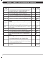
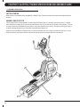
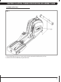
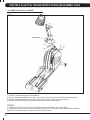
1
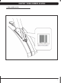
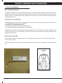
E1X Elliptical
S E R V IC E M A N U A l
table of contents
CHAPTER 1: Serial number location . .................................................................. 1
CHAPTER 2: Important Safety instructions
2.1
2.2
2.3
Before Getting Started ............................................................................................... 2
Read and Save These Instructions . .......................................................................... 3
Electrical Requirements ............................................................................................. 4
CHAPTER 3: Preventative Maintenance
3.1
3.2
3.3
Recommended Cleaning Tips . .................................................................................. 5
Check for Damaged Parts ......................................................................................... 5
Care and Maintenance Instructions ........................................................................... 6
CHAPTER 4: CONSOLE OVERLAY AND WORKOUT DESCRIPTION
4.1
4.2
4.3
4.4
Console Description ...................................................................................................
Workout Overview.......................................................................................................
Workout Setup Steps..................................................................................................
Using Fitness Network................................................................................................
7
8
9
11
CHAPTER 5: Manager MODE
5.1
5.2
Using Manager Mode ................................................................................................ 12
Manager Mode Overview............................................................................................ 13
CHAPTER 6: Troubleshooting
6.1
6.2
6.3
6.4
6.5
6.6
6.7
Electrical Diagram ......................................................................................................
Console Power Issues................................................................................................
Keypad Issues.............................................................................................................
Resistance Issues.......................................................................................................
Pedal Slipping.............................................................................................................
Noise Issues................................................................................................................
Heart Rate Issues.......................................................................................................
14
19
20
21
22
23
24
CHAPTER 7: PART REPLACEMENT GUIDE
7.1
7.2
7.3
7.4
7.5
7.6
7.7
7.8
7.9
7.10
7.11
7.12
7.13
7.14
7.15
Front Shroud Removal................................................................................................
Console Replacement . ..............................................................................................
Heart Rate Handlebar Replacement . ........................................................................
Heart Rate Grip Replacement.....................................................................................
Cup Holder Replacement............................................................................................
Console Keypad / Overlay Replacement....................................................................
Lower Board Replacement.........................................................................................
Drive Belt Replacement .............................................................................................
ECB Belt Replacement...............................................................................................
ECB Replacement .....................................................................................................
Crank Axle Set Replacement .....................................................................................
Drive Axle Set Replacement.......................................................................................
Level Button Replacement . .......................................................................................
Dual Action Handlebar Replacement..........................................................................
Pedal Replacement.....................................................................................................
25
26
27
28
29
30
32
33
34
35
37
38
40
41
43
i
table of contents
7.16
7.17
7.18
7.19
7.20
7.21 Link Arm Replacement ................................................................................................... 44
Pedal Arm Replacement.................................................................................................. 46
Rear Roller Replacement............................................................................................ 49
Roller Track Replacement........................................................................................... 50
Front Roller Replacement........................................................................................... 51
Test the Elliptical Trainer............................................................................................. 52
CHAPTER 8: elliptical TRAINER specifications and assembly guide
8.1
8.2
8.3
8.4
8.5
8.6
ii
iv
Elliptical Trainer Specifications...................................................................................
Unpacking the Elliptical Trainer...................................................................................
Fasteners and Assembly Tools...................................................................................
Assembly Instructions ................................................................................................
Leveling the Elliptical Trainer......................................................................................
TV Bracket Installation................................................................................................
53
54
55
56
62
63
Chapter 1: Serial number location
1.1 Serial Number Location
1
Chapter 2: Important Safety Instructions
2.1 Before Getting Started
The Matrix E1x Elliptical Trainer is intended for commercial use. To
ensure your safety and protect the equipment, read all instructions
before operating the elliptical trainer.
CHOOSING A SITE
The site should be well lit and well ventilated. Locate the Matrix
Elliptical Trainer on a structurally solid and flat surface. The elliptical
trainer should have a clearance of 20" on one side and behind the
unit, and 12" on the other side from the wall or other equipment.
This zone is to allow easy access to the elliptical trainer and gives
the user an easy exit path from the machine. If the site has a heavy
plush carpet, to protect the carpeting and machinery, you should
place a rigid plastic base under the unit.
Please do not place the Matrix Elliptical Trainer in an area of high
humidity, such as the vicinity of a steam room, indoor pool, or sauna.
Exposure to intensive water vapor or chlorine could adversely affect
the electronics, as well as other parts of the machine.
2
Chapter 2: Important Safety Instructions
2.2 Read and Save these instructions
To ensure your safety and protect the equipment, read all
instructions before operating the MATRIX E1x Elliptical. Trainer
To ensure proper use and safety of the Matrix E1x Elliptical Trainer,
make sure that all users read this manual. Remind the users
that before undertaking any fitness program, they should obtain
complete physical examinations from their physicians. If, at any
time while exercising, the user experiences dizziness, pain, or
shortness of breath, nausea or feels faint, he or she must stop
immediately.
CAUTION! If you experience chest pains, nausea, dizziness,
or shortness of breath, stop exercising immediately and consult your physician before continuing.
CAUTION! Any changes of modifications to this equipment
could void the product warranty.
* Do not use this product outdoors, near swimming pools or in areas
of high humidity.
* Do not allow children or those unfamiliar with its operation on or
near the elliptical trainer. Do not leave children unsupervised around
the unit.
* Never drop or insert objects into any opening. Keep hands away
from moving parts. If the item cannot be reached, contact a Matrix
authorized dealer for assistance.
* Do not wear any clothing that might catch on any moving parts of
the elliptical trainer.
* Do not turn pedals by hand, and do not use this product in bare
feet.
* Do not dismount the elliptical trainer until the pedals are at a complete stop.
* When mounting or dismounting the elliptical trainer, use the stationary handlebar whenever additional stability is required. While
exercising, hold onto the moving arms.
* Never use the elliptical trainer while facing backwards.
* Keep the area around the elliptical trainer clear of any obstructions,
including walls and furniture.
* Assemble and operate the elliptical trainer on a solid, level surface.
* If you plan to move the unit, obtain help and use a hand truck. Do
not grasp any plastic part while lifting or moving the unit. The unit is
too heavy and the plastic parts will break.
* Never operate the unit if it is damaged, not working properly, when
it has been dropped, or has been dropped in water.
* Do not step on or set any object on the top of the pedal covers or
the rear platform.
3
Chapter 2: Important Safety Instructions
2.3 Electrical Requirements
SELF POWERED FEATURES:
On the Matrix E1x Elliptical Trainer, the users pedaling generates the power to initialize and display information on the console. A minimum of
30 RPMs is required to start and maintain enough power to keep the console functional. If the minimum RPMs are not maintained, the console
will begin to shut down. The elliptical trainer is able to extend the time to show a display on the console if the elliptical trainer is equipped with
an optional battery (Figure A).
SYMPTOMS OF A LOW BATTERY
If the elliptical trainer has not been used for an extended period of time, the battery may require recharging. Symptoms of a low battery include:
1) A "LOW BATTERY" message will appear on the display.
2) Backlighting on the LCD display will be disabled.
3) No one has used the elliptical trainer for an extended period of time.
4) The elliptical trainer powers off immediately after the user stops pedaling.
If the battery must be recharged, use the optional power adaptor to charge the unit. The charger should be connected to the elliptical trainer for
a minimum of eight hours to ensure a thorough charge. If "LOW BATTERY" still appears on the display after full charging, the battery could be
expired and should be replaced.
REPLACING THE BATTERY
The unit's battery is built to last for a long time. However, if you feel the battery may need replacing, it is located behind a plate on the back
side of the console (Figure B).
CAUTION: The battery stored inside the console contains hazardous materials to the environment. Proper disposal of the battery is required by
law.
4
Chapter 3: PREVENTATIVE MAINTENANCE
3.1 recommended cleaning tips
3.2 Check for damaged parts
Preventative maintenance and daily cleaning will prolong the life and look of
your MATRIX E1x Elliptical Trainer
DO NOT use any equipment that is damaged or has worn or
broken parts. Use only replacement parts supplied by Matrix
Fitness Systems.
Please read and follow these tips.
• P
osition the equipment away from direct sunlight. The intense UV light
can cause discoloration on plastics.
• L
ocate your equipment in an area with cool temperatures and low
humidity.
• Clean with a soft 100% cotton cloth.
• C
lean with soap and water or other non-ammonia based all purpose
cleaners.
• W
ipe pedals, console, heart rate grips, and handlebars clean after each
use.
MAINTAIN LABELS AND NAMEPLATES. Do not remove labels
for any reason. They contain important information. If unreadable
or missing, contact Matrix Fitness Systems for a replacement at
866-693-4863 or www.matrixfitness.com.
MAINTAIN ALL EQUIPMENT. Preventative maintenance is the
key to smoothly operating equipment. Equipment needs to be
inspected at regular intervals. Defective components must be
kept out of use until they are repaired. Ensure that any person(s)
making adjustments or performing maintenance or repair of any
kind is qualified to do so. Matrix Fitness Systems will provide
service and maintenance training at our corporate facility upon
request or in the field if proper arrangements are made.
• D
o not pour liquids directly onto your equipment. This can cause damage to the equipment and in some cases electrocution.
• Adjust leveling feet when equipment wobbles or rocks.
• Maintain a clean area around the equipment, free from dust and dirt.
5
Chapter 3: PREVENTATIVE MAINTENANCE
3.3 Care and maintenance instructions
In order to maximize life span, and minimize down time, all MATRIX
equipment requires regular cleaning, and maintenance items
performed on a scheduled basis. This section contains detailed
instructions on how to perform these items and the frequency of
which they should be done. Some basic tools and supplies will be
necessary to perform these tasks which include (but may not be
limited to):
* Metric Allen wrenches
* #2 Phillips head screwdriver
* Adjustable wrench
* Torque wrench (capability to read foot lbs and inch lbs)
* Lint free cleaning cloths
* Teflon based spray lubricant such as "Super Lube" or other Matrix
approved products.
* Mild water soluable detergent such as "Simple Green" or other
Matrix approved products
* Vacuum cleaner with an extendable hose and crevasse tool
attachment.
You may periodically see addendums to this document, as the
Matrix Technical Support Team identifies items that require specific
attention, the latest version will always be available on the Matrix
web site at www.matrixfitness.com.
DAILY MAINTENANCE ITEMS
1) Look and listen for loose fasteners, unusual noises, and any
other indications that the equipment may be in need of service.
2) Clean the elliptical trainer before and after each use, including:
a. Use a damp, soft cloth with water or mild liquid detergent
to clean all exposed surfaces. DO NOT use ammonia, chlorine, or
any acid based cleaners.
b. Keep the console display free of fingerprints and salt build
up caused by sweat.
c. Frequently vacuum the floor beneath the unit to prevent the
accumulation of dust and dirt which can affect the smooth operation
of the unit.
MONTHLY MAINTENANCE ITEMS
1) Inspect the console, handrails, link arms, pedal arms, and
pedals for damage.
2) Check the link / pedal arms for loose joints, tighten hardware as
needed.
3) Check pedal motion and stability.
4) Adjust leveling feet if the equipment rocks or wobbles. 5) Remove the rear shroud, and clean the rollers / tracks to prevent
flat spots caused by dust / dirt.
QuARTERLY MAINTENANCE ITEMS
1) Remove the front shrouds and check belts for damage,
alignment, and proper tension.
6
Chapter 4: Console Overlay and workout description
4.1 Console Description
D
A
B
C
E
G
F
H
A. WORKOUT PROFILE WINDOW:
During a workout, this window displays shapes, made of triangle columns of light, which represent the levels of intensity in a workout
in progress. The height of the furthest column is proportional to the current level of the intensity.
B. INSTRUCTION CENTER:
This window displays step by step instructions for setting up a workout.
C. INFORMATIONAL DISPLAY:
During a workout, three sets of numbers, including Speed, Time, and Distance, display statistics about the progress of the workout.
D. PROGRAM PLUS KEYS:
Press any program key to select one of the workouts. The program keys with a symbol of plus '+' include additional workout options.
Press these keys repeatedly for similar workout options.
E. LEVEL ARROW KEYS:
During a workout, pressing the UP or DOWN ARROW can adjust intensity levels.
F. RIGHT / LEFT ARROW KEYS:
A pair of RIGHT and LEFT ARROW keys are located on the side of SELECT. Use the arrows when setting up a workout to change
workout parameters displayed on the LCD console, such as length of workout, weight, age, heart rate, and intensity level. In addition,
the pair of RIGHT and LEFT ARROW keys are corresponding to the arrows in the LCD display.
G. QUICK START:
Press QUICK START to begin your workout immediately, without having to select a workout program.
H. HOLD TO RESET:
If you need to reset the console during your workout, you can do so by holding down the HOLD TO RESET key for 3 seconds, or until
the display resets.
7
Chapter 4: Console overlay and workout description
4.2 WORKOUT OVERVIEW
Program
Name
8
Description
Default
TIME
Prompt
INPUT
QUICK START
Quick Start is the fastest way to begin exercising and bypasses the setup prompts.
After pressing the QUICK START key, a constant level workout begins.
n/a
N/A
WARM UP
Warm up is a low intensity phase that brings the heart rate into the lower end of the
target zone and increases respiration and blood flow to working muscles.
n/a
Time
COOL DOWN
Cool Down is a low intensity phase that allows the body to begin removing lactic fluid,
and other exercise by-products, which build up in muscles and contribute to soreness. n/a
Time
MANUAL
Manual is a constant intensity level unless it is manually changed.
20 min
Time, Weight
HILL INTERVAL
Hill Intervals is an efficient workout by alternating work intervals and recovery intervals.
20 min
Level, Time,
Weight
RANDOM HILL
Random Hill is an interval training workout that occurs in no regular pattern or
progression.
20 min
Time, Weight
CONSTANT
WATTS
Constant Watts is designed to maintain your watts expenditure at a constant level by
controlling pedaling resistance and prompting you to pedal at a specified RPM. Watts
level may vary above and below your target watts level during this program.
20 min
Watts, Time,
Weight
RANDOM
Random is a workout of constantly changing intensity levels that occur in no regular
pattern or progression.
20 min
Level, Time,
Weight
TIME GOAL
Time Goal sets exercise duration as the workout goal. Once the objective is met, the
workout automatically goes into a cool down phase and ends afterward.
20 min
Time, Weight
DISTANCE GOAL
Distance Goal is designed to build endurance to a certain distance. Once the objective
is met, the workout automatically goes into a cool down phase and ends afterward.
n/a
Distance,
Weight
CALORIES GOAL
Calories Goal is designed to burn a certain number of selected calories. Once the
objective is met, the workout automatically goes into a cool down phase and ends
afterward.
n/a
Calories,
Weight
TARGET HR
Target HR is a higher intensity workout for maintaining a heart rate to achieve maximum
exercise results. The user must wear a heart rate chest strap or keep hands on the
contact heart rate grips continuously. The program adjusts the intensity level, based on
the actual heart rate, to maintain the rate at 80% of the theoretical maximum.
20 min
Age, HR, Time,
Weight
WEIGHT LOSS
Weight Loss is a low intensity workout for burning the body's fat reserves. The user
must wear a heart rate chest strap, or keep hands on the contact heart rate grips
continuously. The program adjusts the intensity level, based on the actual heart rate to
maintain the rate at 65% of the theoretical maximum. 20 min
Age, HR, TIme,
Weight
FIT TEST
Fit Test measures cardiovascular fitness and can be used to monitor improvements in
your endurance.
12 min
Gender, Age,
Level, Weight
Chapter 4: Console Overlay and workout description
4.2 Workout OVERview - Continued
WORKOUT TIPS
1. Matrix Fitness strongly recommends seeing your physician for
a complete physical examination before beginning any fitness
program. Know your physician's recommended heart rate target
zone. If at any time while exercising, you experience faintness,
dizziness, pain, or shortness of breath, you must stop immediately.
2. To mount the elliptical trainer, grasp the front stationary
handlebars and place your feet on the pedals. When you are
comfortably situated, begin pedaling. To dismount the elliptical
trainer, stop pedaling, grasp the front stationary handlebars and get
off the unit.
3. It is highly recommended that you always incorporate the warm
up and cool down period into your workout. Warm up brings the
heart rate into the lower end of the target zone and increases
respiration and blood flow to working muscles. Cool down takes
time for a user's heart rate to return to resting state after vigorous
exercise and reduces the amount of lactic acid in muscle tissue.
PAUSE OPTION
On the Matrix E1x Elliptical Trainer, the users pedaling generates
the power to initialize and display information on the console. A
minimum of 30 RPMs are required to start and maintain enough
power to keep the console functional. If the minimum RPM is not
maintained, the console will begin to shut down. The elliptical
trainer is able to extend the time to show a display on the console
if the elliptical trainer is equipped with an optional battery. If
the console is equipped with a battery, the pause feature will
automatically pause the unit for 30 seconds after the user stops
pedaling. After 30 seconds, the unit will reset.
SYMPTOMS OF A LOW BATTERY
If the elliptical trainer has not been used for an extended period
of time, the battery may require recharging. Symptoms of a low
battery include:
1) A "LOW BATTERY" message will appear on the display.
2) Backlighting on the LCD display will be disabled.
3) No one has used the elliptical trainer for an extended period of
time.
If the battery must be recharged, use the optional power adaptor to
charge the unit. The charger should be connected to the elliptical
trainer for a minimum of eight hours to ensure a thorough charge. If
"LOW BATTERY" still appears on the display after full charging, the
battery could be expired and should be replaced.
4.3 wORKOUT sETUP sTEPS
1. Begin to pedal the elliptical trainer.
2. Use the PROGRAM PLUS keys to enter the program, or use the
RIGHT / LEFT ARROW keys to scroll to the desired program. The
program name is displayed in the PROMPT AREA.
3. Use the RIGHT / LEFT ARROW keys to scroll to desired
parameter values displayed in the PROMPT AREA.
4. Press the SELECT key to confirm each selection. Follow the
steps to set up each workout.
QUICK START
Press the QUICK START key and the Workout Profile Window will
display "3, 2, 1, GO!" The workout begins at the default intensity
level, and the workout time counts up from 0 to the maximum
workout time.
WARM UP
1) Press the WARM UP key to enter the program.
2) Select Time using the RIGHT / LEFT ARROW keys, and the
press SELECT.
3) Press START to begin a warm up.
COOL DOWN
1) Press the COOL DOWN key to enter the program.
2) Select Time using the RIGHT / LEFT ARROW keys, and then
press SELECT.
3) Press START to begin a cool down.
MANUAL
1) Press the MANUAL key to enter the program.
2) Select Time using the RIGHT / LEFT ARROW keys, and then
press SELECT.
3) Select Weight using the RIGHT / LEFT ARROW keys, and then
press SELECT.
4) Press START to begin the workout.
HILL INTERVAL
1) Repeatedly press the INTERVAL+ key to select Hill Interval and
the press SELECT.
2) Select Level using the RIGHT / LEFT ARROW keys, and then
press SELECT.
3) Select Time using the RIGHT / LEFT ARROW keys, and then
press SELECT.
4) Select Weight using the RIGHT / LEFT ARROW keys, and then
press SELECT.
9
Chapter 4: Console overlay and workout description
4.3 WORKOUT SETUP STEPS - CONTINUED
RANDOM HILL
1) Repeatedly press the INTERVAL+ key to select Random Hill and
then press SELECT.
2) Select Time using the RIGHT / LEFT ARROW keys, and then
press SELECT.
3) Select Weight using the RIGHT / LEFT ARROW keys, and then
press SELECT.
4) Press START to begin the workout.
CONSTANT WATTS
1) Repeatedly press the MULTI FX- key to select Constant Watts
and then press SELECT.
2) Select Watts using the RIGHT / LEFT ARROW keys, and then
press SELECT.
3) Select Time using the RIGHT / LEFT ARROW keys, and then
press SELECT.
4) Select Weight using the RIGHT / LEFT ARROW keys, and then
press SELECT.
5) Press START to begin the workout.
RANDOM
1) Repeatedly press the MULTI FX+ key to select Random, and
then press SELECT.
2) Select Level using the RIGHT / LEFT ARROW keys, and then
press SELECT.
3) Select Time using the RIGHT / LEFT ARROW keys, and then
press SELECT.
4) Select Weight using the RIGHT / LEFT ARROW keys, and then
press SELECT.
5) Press START to begin the workout.
TIME GOAL
1) Repeatedly press the GOAL+ key to select Time Goal, and then
press SELECT.
2) Select Time using the RIGHT / LEFT ARROW keys, and then
press SELECT.
3) Select Weight using the RIGHT / LEFT ARROW keys, and then
press SELECT.
4) Press START to begin the workout.
DISTANCE GOAL
1) Repeatedly press the GOAL+ key to select Distance Goal, and
then press SELECT.
2) Select Calories using the RIGHT / LEFT ARROW keys, and then
press SELECT.
3) Select Weight using the RIGHT / LEFT ARROW keys, and then
press SELECT.
4) Press START to begin the workout.
10
CALORIES GOAL
1) Repeatedly press the GOAL+ key to select Calories Goal, and
then press SELECT.
2) Select Calories using the RIGHT / LEFT ARROW keys, and then
press SELECT.
3) Select Weight using the RIGHT / LEFT ARROW keys, and then
press SELECT.
4) Press START to begin the workout.
TARGET HR / WEIGHT LOSS
1) Repeatedly press the HEART RATE + key to select Target HR
or Weight Loss, and then press SELECT.
2) Select Age using the RIGHT / LEFT ARROW keys, and then
press SELECT.
3) Select HR using the RIGHT / LEFT ARROW keys, and then
press SELECT.
4) Select Time using the RIGHT / LEFT ARROW keys, and then
press SELECT.
5) Select Weight using the RIGHT / LEFT ARROW keys, and then
press SELECT.
6) Press START to begin the workout.
FIT TEST
1) Select Gender using the RIGHT / LEFT ARROW keys, and then
press SELECT.
2) Select Age using the RIGHT / LEFT ARROW keys, and then
press SELECT.
3) Select Level using the RIGHT / LEFT ARROW keys, and then
press SELECT.
4) Select Weight using the RIGHT / LEFT ARROW keys, and then
press SELECT.
5) Press START to begin the workout.
THE TABLES ON PAGE 11 LIST FIT TEST RESULTS.
Chapter 4: Console overlay and workout description
4.3 Workout Setup steps - continued
FIT TESt'S RESULT FOR MALE
Male
Estimated VO2 Max (ml/kg/min) Per Age Category
Age-Rating
Very Poor
Poor
Fair
Good
Excellent
Superior
15-19
<35.0
35.0-38.3
38.4-45.1
45.2-50.9
51.0-55.9
>55.9
20-29
<33.0
33.0-36.4
36.5-42.4
42.5-46.4
46.5-52.4
>52.4
30-39
<31.5
31.5-35.4
35.5-40.9
41.0-44.9
45.0-49.4
>49.4
40-49
<30.2
30.2-33.5
33.6-38.9
39.0-43.7
43.8-48.0
>48.0
50-59
<26.1
26.1-30.9
31.0-35.7
35.8-40.9
41.0-45.3
>45.3
60+
<20.5
20.5-26.0
26.1-32.2
32.3-36.4
36.5-44.2
>44.2
Fit TEst's Result for FEMALE
Female
Estimated VO2 Max (ml/kg/min) Per Age Category
Age-Rating
Very Poor
Poor
Fair
Good
Excellent
Superior
15-19
<25.0
25.0-30.9
31.0-34.9
35.0-38.9
39.0-41.9
>41.9
20-29
<23.6
23.6-28.9
29.0-32.9
33.0-36.9
37.0-41.0
>41.0
30-39
<22.8
22.8-26.9
27.0-31.4
31.5-35.6
35.7-40.0
>40.0
40-49
<21.0
21.0-24.4
24.5-28.9
29.0-32.8
32.9-36.9
>36.9
50-59
<20.2
20.2-22.7
22.8-26.9
27.0-31.4
31.5-35.7
>35.7
60+
<17.5
17.5-20.1
20.2-24.4
24.5-30.2
30.3-31.4
>31.4
4.4 USING Fitness NETWORKING
The two RJ45 networking ports are equipped in the Matrix E1x Elliptical Trainer. These ports allow the elliptical trainer to be connected to a
fitness entertainment system and / or a fitness network such as FitLinxx®.
C-SAFE / CARDIO PORT
The ports are located on the back of the console. The C-SAFE port enables the elliptical trainer to upload user workout statistics to a fitness
network database. The CARDIO port is compatible to entertainment protocol such as Cardio Theater® or Broadcast Vision™.
11
Chapter 5: MANAGER MODE
5.1 Using Manager Mode
The Manager's Custom Mode allows the club owner to customize
the elliptical trainer for the club.
1) To enter Manager Mode, press and hold down the LEVEL
ARROW keys. Continue to hold down these two keys until the display reads Manager Mode
2) To scroll through the list of options in Manager Mode, use the
LEFT / RIGHT ARROW keys, or LEVEL ARROW keys. Each of the
custom settings will show on the display.
3) To select a custom setting, press the SELECT key when the
desired setting is shown.
4) To change the value of the setting, use the LEFT / RIGHT
ARROW keys or the LEVEL ARROW keys.
5) To confirm and save the value of the setting, press the QUICK
START key. Setting saved will appear on the display. To exit the
setting without saving, press the HOLD TO RESET key, or wait 5
seconds, the system will resume normal function.
12
Chapter 5: MANAGER MODE
5.2 Manager mode overview
Custom
Settings
Default
Minimum
Maximum
Unit
description
Maximum Time
60
5
95
Minute
Maximum workout duration.
Default Time
60
5
95 (limited
to max time
setting)
Minute
Default start time in all programs.
Default level
1
1
10
Level
Default start level in all programs.
MAXIMUM LEVEL
20
1
20
N/A
Maximum allowable resistance level.
Default Weight
150 lb. / 68 kg
80 lb. / 36 kg
400 lb. / 182 KG
Pound /
Kilogram
Default weight used in calorie calculations
and HR programs.
default Age
30
15
100
Age
Default age used in HR programs.
accumulated
distance
N/A
N/A
65,000 Miles /
104,000 KM
Mile / Kilometer
Total distance on treadmill., not editable.
TO RESET: Press and hold INCLINE
DOWN and SPEED DOWN for 3-5
seconds.
accumulated
time
N/A
N/A
65,000 hours
Hour
Total time on treadmill, not editable. TO
RESET: Press and hold INCLINE DOWN
and SPEED DOWN for 3-5 seconds. Pause Time
30 Sec
30 Sec
180 Sec
Second
This is the maximum time during which
a workout can remain in pause mode.
Restrictions exist for the machine not
equipped with a battery.
Model
EL
N/A
N/A
N/A
CB - Upright bike, RB - Recumbent Bike,
EL - Elliptical Trainer, SI - Stepper
Language
English
N/A
N/A
N/a
The native language prompts in the
display.
Software
version
N/A
N/A
N/A
N/A
Software version is not editable.
units
Metric
Metric
English
N/A
The measurement unit prompts for weight,
distance, and speed.
error log
N/A
N/A
N/A
N/A
Error log is not editable. Hold the RIGHT
and LEFT ARROW keys simultaneously to
erase error log.
METS
Off
on
off
n/a
If this option is on, the METS prompt
becomes an individual display in PROMPT
AREA. If this option is off, there will be
an alternate prompt in RPM and METS at
the lower right corner of the WORKOUT
PROFILE WINDOW.
Reset All
N/A
N/A
N/A
N/A
This function will clear all custom settings
stored on the unit and returns them to
factory settings. Hold the RIGHT and
LEFT ARROW keys simultaneously to
reset.
13
Chapter 6: TROUBLESHOOTING
6.1 Electrical Diagrams
Electrical Block Diagram
14
Chapter 6: Troubleshooting
6.1 Electrical Diagrams
Wiring diagram INstruction
15
Chapter 6: TROUBLESHOOTING
6.1 Electrical Diagrams
P01 - Console Cable
16
Chapter 6: Troubleshooting
6.1 Electrical diagrams
P02 - Pulse sensor wire
17
Chapter 6: Troubleshooting
6.1 Electrical Diagrams
P03 - Generator Wire
18
Chapter 6: TROUBLESHOOTING
6.2 Troubleshooting - CONSOLE POWER issues
NO Display on the console or the display is dim
Possible Causes:
1)
2)
3)
4)
The console is damaged or the console cable is not connected properly.
Poor connection to the terminals on the lower board.
The lower board is damaged.
The ECB is damaged.
SOLUTION
1) Check the console cable connections at the console and lower board.
2) Unplug the console cable at the console. Use a multi-meter to check if the voltage between the 1 (VCC) and 7 (Ground) pins of the console
cable is greater than 12 (Figure A).
a. If the voltage is greater than 12, replace the console.
3) Unplug the ECB wiring harness from the lower board and pedal the machine. Use a multi-meter to check to see if the voltage from the ECB
is variable (voltage should vary depending on the RPM used).
a. If the voltage is variable, replace the lower board.
b. If the voltage is not variable, replace the ECB.
c. If the issue is still not resolved after replacing the ECB and lower board, replace the console cable.
Figure A
19
Chapter 6: Troubleshooting
6.3 troubleshooting - Keypad Issues
All or Some of the Function keys do not respond
Possible Causes:
1) The keypad connecting ribbon cable has not been properly fit to the console connector.
2) The keypad is damaged.
3) The console control board is damaged.
SOLUTION:
1) Remove the back of the console and check to see if the keypad connecting ribbon cable is connected properly to the console control board.
Reconnect the cable and test the keypad for function (Figures A, B, & C).
a. If the keypad still does not respond, replace the affected keypad.
b. If the keypad does not resolve the issues, replace the console.
Figure B
Figure A
Figure C
20
Chapter 6: troubleshooting
6.4 Troubleshooting - Resistance issues
NO RESISTANCE CHANGE OR ALWAYS HIGH RESISTANCE
POSSIBLE CAUSES:
1)
2)
3)
4)
The
The
The
The
console is damaged or the console cable is not connected properly.
console cable is damaged.
ECB is damaged.
lower board is damaged.
SOLUTION:
1) Check the console cable connections at the console and lower board.
2) Unplug the ECB wiring harness from the lower board and pedal the machine. Using a multi-meter, check the ohm readout from the ECB
wiring harness (Figure A).
a. If the ohm reading is between 10 and 15, replace the lower board.
b. If the ohm reading is not between 10 and 15, replace the ECB.
c. If the issue is not resolved by the lower board or ECB, replace the console.
d. If the issue is not resolved by the lower board, ECB, or console, replace the console cable.
Figure A
21
Chapter 6: Troubleshooting
6.5 Troubleshooting - Pedal Slipping
SLIPPING WHILE PEDALING
POSSIBLE CAUSES
1) Belt tension is not enough.
2) The one way bearing is damaged.
SOLUTION:
1) Check the drive belt tension. The drive belt should have 120 ft. / lbs of tension for a used belt and 150 ft. / lbs of tension for a new belt.
2) If the belt tension is correct and the belt is still slipping, the one way bearing is damaged. Replace the drive assembly (Figure A).
Figure A
22
Chapter 6: Troubleshooting
6.6 troubleshooting - Noise issues
KNOCKING OR CREAKING NOISES
POSSIBLE CAUSES:
1)
2)
3)
4)
5)
The pedal is connected to the link arm too loosely.
The pedal arm is connected to the link arm too loosely or the connection is missing the washers.
Belt tension is too loose, or belt is dirty.
The crank bearings are damaged or worn out.
The link arm bearings are damaged or worn out.
SOLUTION:
1) Clean and tighten the belts.
2) Tighten the connections between the pedal and link arm (Figure A).
3) Tighten the connections between the pedal arm and link arm, and check to see that the washers are not missing (Figures B & C).
4) Replace the crank.
5) Replace the link arms.
Figure A
Figure B
Figure C
23
Chapter 6: Troubleshooting
6.7 TROUBLESHOOTING - HEART RATE ISSUES
Heart Rate does not work
POSSIBLE CAUSES:
1)
2)
3)
4)
5)
There is not a good contact between the user and HR grips or HR strap.
The HR strap is at a low battery status.
The HR strap is damaged.
The HR grips are damaged.
The HR board in the console is damaged.
SOLUTION:
1) Re-center the HR strap on the user's chest as shown in Figure A. 2) Replace the battery in the HR Strap.
3) Wet the user's hand, then reestablish contact with the HR grip.
4) Replace the HR strap.
5) Replace the HR grips.
6) Replace the console.
FIgure A
24
Chapter 7: Part replacement guide
7.1 Front Shroud Removal
1) Remove the 18 screws holding the shrouds in place using a #2 Phillips Screwdriver.
2) There should be 8 screws on the left side (Figure A) and 10 screws on the right side (Figure B).
Figure A
Figure B
3) Once the screws are removed, the shroud will split into 2 pieces to be removed.
4) Figure C shows the elliptical trainer with both shrouds removed.
Figure C
25
Chapter 7: Part Replacement Guide
7.2 CONSOLE REPLACEMENT
1) Remove the 4 screws holding the console to the frame (Figure A & B).
Figure A
Figure B
2) Disconnect the console cable, HR, and level wire connections from the defective console and remove the console (Figure C).
Figure C
3) Reinstall the wire connections to the new console.
4) Carefully push the wires into the console and mast until they are clear of the console / mast connection and attach the new console to the
mast using the 4 screws you removed in Step 1.
5) Test the elliptical trainer for function as outlined in Section 7.21.
26
CHAPTER 7: PART REPLACEMENT GUIDE
7.3 HEART RATE HANDLEBAR REPLACEMENT
1) Remove the 4 screws holding the heart rate handlebar to the console mast being careful to support the handlebar (Figure A).
Figure A
2) Carefully pull the wires from the console mast until the connectors are showing, and then disconnect the 2 wires from the handlebar and
remove the defective handlebar (Figure B).
Figure B
3) Reconnect the 2 wires to the new heart rate handlebar (the wires are not side specific).
4) Carefully push the 2 wires back into the console mast, and attach the handlebar to the console mast using the 4 screws removed in Step 1.
5) Test the elliptical trainer for function as outlined in Section 7.21.
27
Chapter 7: Part Replacement Guide
7.4 HEART RATE GRIPS REPLACEMENT
1) Using a flat screwdriver, pry the silver metal heart rate plate away from the plastic of the HR grip (Figure A).
2) Remove the 2 screws holding the HR grip together (Figure B). NOTE: You may need to remove the console to give access to the HR grip
screws.
Figure A
Figure B
3) Disconnect the HR Grip wire and remove the cap and the two halves of the HR grip (Figures C, D, & E).
Figure C
Figure D
4) Reverse Steps 1-3 to install new HR grips.
5) Test the elliptical trainer for function as outlined in Section 7.21.
28
Figure E
Chapter 7: Part Replacement Guide
7.5 CUP HOLDER REPLACEMENT
1) Remove the 2 screws holding the cup holder to the console mast (Figure A).
Figure A
2) Remove the cup holder (Figure B).
Figure B
3) Reverse Steps 1-2 to install a new cup holder. 29
Chapter 7: Part Replacement Guide
7.6 CONSOLE KEYPAD / OVERLAY REPLACEMENT
1) Remove the console as outlined in Section 7.2.
2) Remove the 6 screws holding the console back to the front (Figure A). NOTE: If just replacing an overlay, only complete Steps 4, 8, & 9. 3) Remove the wire connections holding the console back to the front (Figure B).
Figure A
Figure B
4) Disconnect the console back from the front (Figure C).
5) Using a razor blade, carefully peel up one corner of the overlay and then remove the whole overlay (Figure D). Remove any access
adhesive from the plastic.
Figure C
30
Figure D
Chapter 7: Part Replacement Guide
7.6 CONSOLE KEYPAD / OVERLAY REPLACEMENT - CONTINUED
6) Disconnect the appropriate ribbon cable for the keypad that you are replacing (Figures E - G).
Figure E
Figure F
7) Again using a razor blade, carefully peel up one corner of the defective keypad and the remove it from the console.
8) Remove the backing from the new keypad (Figure H). Install the new keypad by sliding the ribbon cable through the slot in the console and
plug it in to the appropriate console housing. Be careful to seat the ribbon cable correctly.
Figure G
Figure H
9) Remove the backing from the new overlay. Install the new overlay into the console housing over the keypad. Be careful to avoid air bubbles
and misalignment.
10) Reverse Steps 1-4 to re-install the console.
11) Test the elliptical trainer for function as outlined in Section 7.21.
31
Chapter 7: Part Replacement Guide
7.7 LOWER BOARD REPLACEMENT
1) Remove the front shrouds as outlined in Section 7.1.
2) Disconnect the 3 wire connections to the lower board (Figure A).
Figure A
3) Remove the 2 screws holding the lower board to the frame (Figure B).
Figure B
4) Remove the lower board.
5) Reverse Steps 1-4 to install a new lower board. 6) Test the elliptical trainer for function as outlined in Section 7.21.
32
Chapter 7: Part Replacement Guide
7.8 DRIVE BELT REPLACEMENT
1) Remove the front shrouds as outlined in Section 7.1.
2) Remove the idler tension eye bolt nut (Figure A).
3) Once the eye bolt nut is removed, it will allow you to pivot the idler, loosening tension on the belt (Figures B & C).
fIGURE a
fIGURE b
4) Now that tension has been loosened, remove the drive belt (Figure D).
fIGURE c
fIGURE d
5) Reverse Steps 1-4 to reinstall a new belt. 6) Tighten the idler eye bolt so that the drive belt is tensioned to 120 ft. / lbs for a used belt and 150 ft. / lbs for a new belt.
7) Test the elliptical trainer for function as outlined in Section 7.21.
33
Chapter 7: Part Replacement Guide
7.9 ECB (ELECTRONIC BRAKE) BELT REPLACEMENT
1) Remove the front shrouds as outlined in Section 7.1.
2) Loosen the 2 nuts holding the ECB to the ECB mounting bracket (Figure A).
3) Remove the 2 tension eye bolts on the ECB mounting bracket (Figure B).
fiGURE a
fIgure b
4) Remove the screw holding the ECB wire harness in place (Figure C).
5) Now that the tension has been loosened, pull the ECB up and remove the ECB belt (Figure D).
fIGURE c
6) Reverse Steps 1-5 to install a new ECB belt. 7) Test the elliptical trainer for function as outlined in Section 7.21.
34
fIgure D
Chapter 7: Part Replacement Guide
7.10 ECB (ELECTRONIC BRAKE) REPLACEMENT
1) Remove the front shrouds as outlined in Section 7.1.
2) Disconnect the ECB wire harness (Figure A).
3) Remove the 2 nuts holding the ECB to the ECB mounting bracket (Figure B).
Figure A
Figure B
4) Disconnect the 2 tension eye bolts from the ECB mounting bracket (Figure C).
5) Remove the 4 screws holding down the ECB (Figure D). When reinstalling the ECB frame, torque the screws to 12 N-m. Figure C
Figure D
35
Chapter 7: Part Replacement Guide
7.10 ECB (ELECTRONIC BRAKE) REPLACEMENT - CONTINUED
6) Remove the screw holding the ECB wire harness in place (Figure E).
Figure E
7) Remove the defective ECB (Figure F).
Figure F
8) Reverse Steps 1-7 for installing a new ECB. 9) Tighten the eye bolts on the ECB mounting bracket so that the ECB belt is tensioned to 60 ft. / lbs for a used belt and 75 ft. / lbs for a new
belt.
10) Test the elliptical trainer for function as outline in Section 7.21.
36
Chapter 7: Part Replacement Guide
7.11 Crank axle set replacement
1)
2)
3)
4)
Remove
Remove
Remove
Remove
the
the
the
the
front shrouds as outlined in Section 7.1.
drive belt as outlined in Section 7.8.
ECB belt as outlined in Section 7.9.
large nut holding the crank axle set to the frame (Figure A).
Figure A
5) Use a hammer to push the crank axle set to the left side and out of the frame (Figure B). NOTE: A piece of wood or other material should
be used between the drive axle set and the hammer to prevent damage to the drive axle threads.
Figure B
6) Reverse Steps 1-5 to install a new crank axle set. 7) Test the elliptical trainer for function as outlined in Section 7.21.
37
Chapter 7: Part Replacement Guide
7.12 drive axle set replacement
1) Remove the front shrouds as outlined in Section 7.1.
2) Remove the drive belt as outlined in Section 7.8.
3) Pull the cap off of the crank / pedal arm connection (Figure A).
4) Remove the large nut holding the pedal arm to the crank (Figure B). NOTE: Be sure to notice the order of the washers as you remove
them for reinstallation (Figure C).
Figure A
Figure B
5) The front of the link arm can now be lifted away (Figure D).
Figure C
38
Figure D
chapter 7: part replacement guide
7.12 drive axle set replacement - continued
6) Remove the screw / nut holding the crank to the drive axle set (Figure E), and remove the crank (Figure F).
Figure E
Figure F
7) Remove the large nut holding the drive axle set to the frame (Figure G).
8) Use a hammer to push the drive axle to the right side and out of the frame (Figure H). NOTE: A piece of wood or other material should be
used between the drive axle set and the hammer to prevent damage to the drive axle threads.
Figure G
Figure H
9) Test the elliptical trainer for function as outlined in Section 7.21.
39
Chapter 7: Part Replacement Guide
7.13 lEVEL button ASSEMBLY replacement
1) Remove the 2 screws holding the level button assembly to the dual action handlebar (Figure A).
2) Remove the cap on the pivot of the dual action handlebar (Figure B).
Figure A
Figure B
3) Disconnect the level button wire within the pivot tube (Figure C).
4) Carefully pull the wire up through the dual action handlebar and remove the defective level button assembly (Figure D).
FiguRe C
5) Reverse Steps 1-4 to install a new level button assembly. 6) Test the elliptical trainer for function as outlined in Section 7.21.
40
Figure D
Chapter 7: Part Replacement Guide
7.14 Dual action handlebar replacement
1) Remove the two caps covering the screw / nut holding the dual action handlebar to the link arm (Figure A & B).
Figure A
Figure B
2) Remove the screw / nut holding the dual action handlebar to the link arm (Figure C). This will allow one side of the link arm to be moved
away from the dual action handlebar.
3) Remove the cap on the pivot of the dual action handlebar (Figure D).
Figure C
Figure D
41
Chapter 7: Part Replacement Guide
7.14 Dual action handlebar replacement - CONTINUED
4) Remove the 4 screws holding the dual action handlebar to the pivot tube (Figure E).
Figure E
5) You can now remove the dual action handlebar (Figure F).
Figure F
6) Reverse Steps 1-5 to install a new dual action handlebar. NOTE: When reinstalling the dual action handlebar, tighten the 4 screws removed
in Step 5 to 34 N-m torque. 7) Test the elliptical trainer for function as outlined in Section 7.21.
42
Chapter 7: Part Replacement Guide
7.15 Pedal Replacement
1) Remove the 4 screws holding the link arm assembly to the pedal arm (Figure A).
2) Remove the 3 screws holding the pedal assembly to the pedal arm (Figure B). Remove the hardware and 3 hole plate.
Figure A
Figure B
3) Slide the link arm assembly off of the pedal arm (Figure C). NOTE: Make sure to notice the order of the washers for reinstallation (wavy,
Teflon, pedal assembly, Teflon, 3 hole plate, screws).
4) Peel up the pedal foot pad, and remove the 4 screws holding the pedal to the link arm (Figure D).
Figure C
Figure D
5) Reverse Steps 1-4 to install a new pedal. 6) Test the elliptical trainer for function as outlined in Section 7.21.
43
Chapter 7: Part Replacement Guide
7.16 LINK ARM REPLACEMENT
1) Remove the two caps covering the screw / nut holding the dual action handlebar to the link arm (Figure A & B).
Figure A
Figure B
2) Remove the screw / nut holding the dual action handlebar to the link arm (Figure C). This will allow one side of the link arm to be moved
away from the dual action handlebar.
3) Remove the 4 screws holding the link arm assembly to the pedal arm (Figure D).
Figure C
44
Figure D
Chapter 7: Part Replacement Guide
7.16 Link ARM REPLACEMENT - CONTINUED
4) Remove the 3 screws holding the pedal assembly to the pedal arm (Figure E). Remove the hardware and 3 hole plate.
5) Slide the link arm assembly off of the pedal arm (Figure F). NOTE: Make sure to notice the order of the washers for reinstallation (wavy,
Teflon, pedal assembly, Teflon, 3 hole plate, screws).
Figure E
Figure F
6) Peel up the pedal foot pad, and remove the 4 screws holding the pedal to the link arm (Figures G & H).
Figure G
Figure H
7) Reverse Steps 1-6 to install a new link arm. 8) Test the elliptical trainer for function as outlined in Section 7.21.
45
Chapter 7: Part Replacement Guide
7.17 Pedal Arm REPLACEMENT
1) Remove the front shrouds as outlined in Section 7.1.
2) Pull the cap off of the crank / pedal arm connection (Figure A).
3) Remove the large nut holding the pedal arm to the crank (Figure B). NOTE: Be sure to notice the order of the washers as you remove
them for reinstallation (Figure C).
Figure A
FIgure B
4) The front of the link arm can now be lifted away (Figure D).
Figure C
46
Figure D
Chapter 7: Part Replacement Guide
7.17 Pedal ARM REPLACEMENT - CONTINUED
5) Remove the 4 screws holding the link arm assembly to the pedal arm (Figure E), move the link arm out of the way (Figure F).
FIgure E
Figure F
6) Remove the 6 screws holding the rear shroud in place and move the shroud out of the way (Figures G & H).
FIgure G
Figure H
47
Chapter 7: Part Replacement Guide
7.17 Pedal ARM REPLACEMENT - CONTINUED
7) Remove the 5 screws holding down the roller cover, remove the cover (Figure I).
Figure I
Figure H
8) Move the pedal arm so that the rollers are below the hole created by removing the roller cover, remove the pedal arm (Figures J & K).
Figure J
9) Reverse Steps 1-8 to install a new pedal arm. 10) Test the elliptical trainer for function as outlined in Section 7.21.
48
Figure K
Chapter 7: Part Replacement Guide
7.18 Rear Roller Replacement
1) Follow Steps 1-8 from Section 7.17 to remove the pedal arm. 2) Remove the screw holding the rear roller to the pedal arm (Figure A).
Figure A
3) Press a large tie rod fork between the 2 rear rollers forcing them off of the pedal arm (Figures B & C).
Figure B
Figure C
4) Reverse Steps 1-2 to install new rear rollers.
5) Test the elliptical trainer for function as outlined in Section 7.21.
49
Chapter 7: Part Replacement Guide
7.19 Roller Track Replacement
1) Follow Steps 1-8 from Section 7.17 to remove the pedal arm.
2) Remove the 8 screws holding down the covering plate and remove it (Figure A).
Figure A
3) Remove the 12 screws holding down the roller track and remove it (Figure B).
Figure B
4) Reverse Steps 1-3 to install a new roller track. 5) Test the elliptical trainer for function as outlined in Section 7.21.
50
Chapter 7: Part Replacement Guide
7.20 front roller replacement
1) Remove the screw holding the front roller to the stabilizer (Figure A).
Figure A
2) Remove the front roller (Figure B).
Figure B
3) Reverse Steps 1-2 to install a new front roller. 51
Chapter 7: Part Replacement Guide
7.21 Testing the elliptical trainer
Once the unit or replacement part is fully installed and assembled and
properly placed on the floor, use the following instructions to test
the machine:
1) Without hitting start or entering any program modes, stand on the machine and hold the handlebars while initiating movement to simulate
exercising. While moving, listen for any odd noises or squeaks.
2) After stopping movement, press the QUICK START button and begin using the machine.
3) Grasp the hand grips to check for proper heart rate response.
4) Press the level up and down buttons both on the hand grips and on the console to make sure resistance is fully functional.
5) If everything functions properly, stop pedaling and the unit will reset to normal operation after 30 seconds.
52
Chapter 8: elliptical trainer Specifications and Assembly Guide
8.1 ELLIPTICAL SPECIFICATIONS
CONSOLE
Display Screen
Workout Profile Window - 7" blue backlit graphic LCD display
Instruction Center - 14 character red LED alphanumeric display
Informational Display - 3 numeric 7 segment display (3 sets)
Display Readout
Time, Distance, Calories, Speed, Level, Watts, METS, Heart Rate, Profile
Programs
Manual, Hill Interval, Random Interval, Time Goal, Distance Goal,
Calories Goal, Constant Watts, Random, Target HR, Weight Loss, Fit
Test, Warm Up, Cool Down.
On-the-fly Program Change
Yes
Telemetric HR Receiver
Yes
Contact HR Sensors
Yes
Program Quick Keys
Yes
One-Touch Quick Start
Yes
Pause Time
30 Seconds
Language Options
English, Italian, German, Spanish, French, Dutch, Portuguese, Japanese
Technical Data
Resistance Technology
JID™ Hybrid Generator
Resistance Levels
20
Drive System
Two stage belt driven
Stride Drive System
Forward and Reverse
Stride Length
19" / 48 cm
Dimensions (L x W x H)
83" x 31" x 67" / 211 x 79 x 170 cm
Product Weight
333 lbs / 151 kg
Max User Weight
400 lbs / 182 kg
Power Requirements
Self Powered
Special Features
Handlebar Design
Multi position dual action arms and ergo bend stationary
Thumb Switch Controls
Yes, equipped in the dual action arms
Pedals
Auto positioning pedals with front safety fences
Integrated Reading Rack
Yes
Q-factor
3.75"
Entertainment Solutions
FITCONNEXION™ Ready
Yes
Networking Capabilities
CSAFE Ready, Fitlinxx™ certified
53
Chapter 8: Elliptical trainer SPECIFICATIONS AND ASSEMBLY GUIDE
8.2 Unpacking the elliptical trainer
The Matrix E1x Elliptical Trainer is carefully inspected before shipment, so it should arrive in good operating condition. Matrix Fitness ships the
unit in the following pieces:
NOTE: If these parts are missing from the package, please contact Matrix Fitness at once.
54
Chapter 8: Elliptical trainer SPECIFICATIONS AND ASSEMBLY GUIDE
8.3 Fasteners and Assembly Tools
55
chapter 8: elliptical trainer specifications and assembly guide
8.4 ASSEMBLY INSTRUCTIONS
GETTING STARTED
Read the owner's manual before setting up the Matrix E1x Elliptical Trainer. Place the unit where it will be used before beginning the setup
procedure.
MAKING A CHOICE OF SITE
The site should be well lit and well ventilated. Locate the Matrix E1x Elliptical Trainer on a structurally solid and flat surface. The elliptical
trainer should have a clearance of 20" on one side and behind the unit, and 12" on the other side from the wall or other equipment. This zone
is to allow easy access to the elliptical trainer and gives the user an easy exit path from the machine. If the site has a heavy plush carpet, to
protect the carpeting and machinery, you should place a rigid plastic base under the unit.
Please do not place the Matrix E1x Elliptical Trainer in an area of high humidity, such as the vicinity of a steam room, indoor pool, or sauna.
Exposure to intensive water vapor or chlorine could adversely affect the electronics, as well as other parts of the machine.
20"
20"
56
12"
Chapter 8: ELLIPTICAL trainer SPECIFiCATIONS and ASSEMBLY GUIDE
8.4 Assembly Instructions
STEP 1
1) LIft up the Main Body at the front end. Insert a wooden or hard box underneath the Main Body while you lift it up.
2) Fasten the Front Foot to the Main Body using two screws (Z10).
57
Chapter 8: elliptical trainer specifications and assembly guide
8.4 ASSEMBLY INSTRUCTIONS - CONTINUED
STEP 2
CONSOLE MAST
1)
2)
3)
4)
Thread the Console Mast through the Console Mast Boot.
Feed the Console Cable through the Console Mast. Tape the Console Cable to the top of the Console Mast to secure it temporarily.
Attach the Console Mast to the Base Frame using two screws (Z03), four washers (Z04), and two nylon nuts (Z07).
Attach the Cup Holder Bracket to the Console Mast using the existing screws in the Console Mast.
CONSOLE
1) Connect the Console Cable inside the Console, and unscrew the four screws attached to the back of the Console.
2) Carefully push the wires into the Console and Console Mast until they are clear of the Console / Console Mast connection and attach the
Console to the Console Mast using the 4 screws taken from the back of the Console.
58
Chapter 8: elliptical trainer specifications and assembly guide
8.4 ASSEMBLY INSTRUCTIONS - CONTINUED
STEP 3
HR Handlebar
1) Plug in the heart rate wires to the wires from the Console Mast.
2) Attach the Heart Rate Handlebar to the Console Mast using four screws (Z25) and four washers (Z24).
CUP HOLDER
Attach the Cup Holder to the Cup Holder Bracket using two screws (Z22).
59
Chapter 8: Elliptical trainer specifications and assembly guide
8.4 Assembly Instructions - Continued
STEP 4
1) Attach the Dual Action Handlebars (R) and (L) to the Console Mast using eight screws (Z18), and place the handlebar caps (G24) around the
handlebars.
2) Fasten the Link Arms (R) and (L) to the Pedal Arms using eight screws (Z01) and eight washers (Z02).
3) Attach the Dual Action Handlebars to the Link Arms using two bolts (Z06), four bushings (Z05), and two nylon nuts (Z07).
4) Align the cut out inside the Link Arm Caps (Z08) with the link arm mounting hole. Apply pressure to the cap until it snaps into place.
60
Chapter 8: elliptical trainer specifications and assembly guide
8.4 Assembly instructions - continued
61
Chapter 8: elliptical trainer specifications and assembly guide
8.5 LEVELING THE ELLIPTICAL
STABILIZING the MATRIX E1x Elliptical Trainer
After placing the unit where it will be used, check its stability. If the elliptical trainer is placed on an uneven surface, adjusting the adjustable
levelers located underneath the base frame can help, but will not compensate for extremely uneven surfaces. To adjust, loosen the nut, and
turn the leveler until the rocking motion ceases, and both levelers rest firmly on the floor. Retighten the nut.
62
chapter 8: elliptical specifications and assembly guide
8.6 tv Bracket installation
1) Remove the 4 screws and plate from the front side of the console mast (Figure A).
2) Fish the TV power wire and coax cable from within the console mast and push it out the hole in the front of the console mast (Figure B).
NOTE: You may need to remove the console to get these 2 wires out.
3) Remove the protective coating from around the coax cable (Figure C).
4) Connect the coax cable and power wire from the console mast with the cables coming from the TV bracket (Figure D). NOTE: You will need
to use a coax adaptor sent with the bracket (Figure E). Be sure to orientate the TV bracket the correct way when installing.
5) Attach the TV bracket to the console mast using the 4 screws removed in Step 1 (Figure F).
6) Attach the small bracket to the TV bracket using the hardware provided. There should be 1 lock washer and 3 flat washers on each side
(Figure G).
7) Attach the TV to the TV bracket using 4 silver screws sent with the TV (Figure H).
8) Connect the coax and TV power wire to the TV (Figure I).
9) Unbox the power cord from the TV box and plug into the port at the bottom front of the elliptical trainer (Figure J).
10) Run a coax cable to the elliptical trainer and plug it into the port at the bottom front of the elliptical trainer (Figure K).
11) Remove the protective film from the TV screen (Figure L).
12) Test the TV for function, program for channels as needed.
Figure A
figure C
Figure B
figure d
63
chapter 8: elliptical specifications and assembly guide
8.6 tv bracket installation - continued
Figure E
Figure G
64
Figure F
Figure H
chapter 8: elliptical specifications and assembly guide
8.6 tv bracket installation - continued
Figure I
Figure K
Figure J
Figure L
65
NOTES
66
M ATr i x F i t ness s y s t ems c o r p.
1610 Landmark Drive C ottage G rove wi 5 3 5 2 7 U S A
TO LL FREE 866. 693. 4863
w w w. m a t r i x f i t n e s s . c o m
FA X 6 0 8 . 8 3 9 . 1 7 1 7
KO
REV. 1
67