1
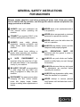
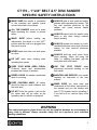
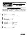
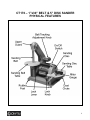
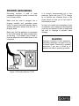
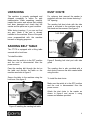
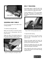
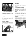
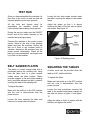
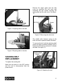
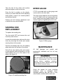
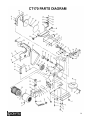
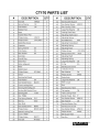
CT170 1”x30” BELT & 5” DISC SANDER User Manual TABLE OF CONTENTS General Safety Instructions for Machines ............................................................... 3 Specific Safety Instructions..................................................................................... 4 CT170 Features ...................................................................................................... 5 Physical Features ................................................................................................... 6 Proper Grounding ................................................................................................... 7 Un-Packing ............................................................................................................. 8 Sanding Belt Table.................................................................................................. 8 Dust Chute.............................................................................................................. 8 Sanding Disc Table................................................................................................. 9 Belt Tracking ........................................................................................................... 9 Upper Guard ........................................................................................................... 10 Mounting ................................................................................................................. 10 Test Run ................................................................................................................. 11 Belt Sander Platen .................................................................................................. 11 Squaring the Table.................................................................................................. 11 Sanding Belt Replacement ..................................................................................... 12 Sanding Disc Replacement..................................................................................... 13 Miter Gauge ............................................................................................................ 13 Maintenance ........................................................................................................... 13 Parts Breakdown.....................................................................................................14 Parts List................................................................................................................. 15 Warranty ................................................................................................................. 16 2 GENERAL SAFETY INSTRUCTIONS FOR MACHINES Extreme caution should be used when operating all power tools. Know your power tool, be familiar with its operation, read through the owner’s manual and practice safe usage procedures at all times. ALWAYS read and understand the user manual before operating the machine. CONNECT your machine ONLY to the matched and specific power source. ALWAYS wear safety glasses respirators, hearing protection and safety shoes, when operating your machine. NEVER leave a tool unattended while it is in operation. NEVER allow unsupervised or untrained personnel to operate the machine NEVER reach over the table when the tool is in operation. ALWAYS keep blades, knives and bits sharpened and properly aligned. DO NOT wears loose clothing or jewelry when operating your machine. Wear protective hair covering. ALL OPERATIONS MUST BE performed with the guards in place to ensure safety. A SAFE ENVIRONMENT is important. Keep the area free of dust, dirt and other debris in the immediate vicinity of your machine. ALWAYS use push sticks and feather boards to safely feed your work through the machine. BE ALERT! DO NOT use prescription or other drugs that may affect your ability or judgment to safely use your machine. DISCONNECT the power source when changing drill bits, hollow chisels, router bits, shaper heads, blades, knives or making other adjustments or repairs. ALWAYS make sure that any tools used for adjustments are removed before operating the machine. ALWAYS keep bystanders safely away while the machine is in operation. NEVER attempt to remove jammed cutoff pieces until the blade has come to a full stop. 3 CT170 – 1”x30” BELT & 5” DISC SANDER SPECIFIC SAFETY INSTRUCTIONS MAKE SURE the sander is connected to the matched and specific power source instructed in the manual. ALL THE GUARDS must be in place while operating the sander to ensure safety. MAKE SURE before making any adjustments, the switch is in the “OFF” position and the cord is un-plugged from the power source. NEVER sand more than one work piece at a time. ALWAYS wear a dust mask and safety glasses while operating the sander. The tiny dust particles produced by the sander can cause serious health problems. ALWAYS inspect stock for staples, nails knots or any other foreign material before sanding. ALWAYS operate the sander in a wellventilated area and use a dust collection system for dust removal whenever possible. DO NOT wear loose clothing while operating this sander. ALWAYS hold the work piece firmly when sanding. When not using the table, i.e. sanding free-hand, grip the work piece with both hands. KEEP YOUR WORK AREA CLEAN. Cluttered areas and workbenches increase the chance of accident. USE THE STOP FENCE when performing horizontal sanding on the belt sander. NEVER LEAVE the sander unattended while it is running. MAINTAIN AND SERVICE your sander regularly as instructed in the user manual. KEEP CHILDREN AWAY. All visitors should be kept at a safe distance from the work area. DO NOT force the sander. It will do the job better and will be safer at the operating rate for which it is designed. MAKE SURE you have read and understood all the safety instructions in the manual and you are familiar with your CT170 sander, before operating it. If you fail to do so, serious injury could occur. WARNING The safety instructions given above can not be complete because the environment in every shop is different. Always consider safety first as it applies to your individual working conditions. 4 CT170 – BELT & DISC SANDER FEATURES MODEL CT170 – 1”x30” BELT & 5” DISC SANDER As part of the growing line of Craftex woodworking equipment, we are proud to offer the CT170, a 1”x30” Belt and 5” Disc Sander. The Craftex name guarantees Craft Excellence. By following the instructions and procedures laid out in this user manual, you will receive years of excellent service and satisfaction. The C170 is a professional tool and like all power tools, proper care and safety procedures should be adhered to. Motor Type .......................... .......... Induction Motor Ratings ...................... .......... 1/3-HP, 120-Volts, 60-Hz No Load Speed.................... .......... 3400 RPM Amps ................................... .......... 2.3 Sanding Disc Diameter ........ .......... 5” Sanding Disc Grit................. .......... 80 Sanding Belt Size ................ .......... Length 30” x Width 1” Sanding Belt Grit ................. .......... A 100 Dust Port.............................. .......... Two 1-3/4” Dust Ports Weigh .................................. .......... 16 lbs Warranty .............................. .......... 2 Years 5 CT170 – 1”x30” BELT & 5” DISC SANDER PHYSICAL FEATURES 6 PROPER GROUNDING Grounding provides a path of least resistance for electric current to reduce the risk of electric shock. Make sure the cord is plugged into a properly installed and grounded power outlet. To prevent electrical hazards, have a qualified electrician ensure that the line is properly wired. Make sure that the appliance is connected to an outlet having the same configuration as the plug. If an adaptor plug is used, it must be attached to the metal screw of the receptacle. It is strongly recommended not to use extension cords with your CT170. Always try to position your machine close to the power source so that you do not need to use extension cords. In case if you really find it necessary to use an extension cord, make sure the extension cord does not exceed 50-feet in length and the cord is 14-gauge to prevent motor damage. WARNING Improper connection of the equipmentgrounding conductor can result in a risk of electric shock. Check with a qualified electrician if you are in doubt as to whether the outlet is properly grounded. Figure-1 120-Volts outlet for CT170 7 UNPACKING DUST CHUTE The machine is properly packaged and shipped completely in carton for safe transportation. When unpacking, carefully inspect the carton and ensure that nothing has been damaged and check that the sander and the parts are in good condition. For optimum dust removal the sander is equipped with two dust chutes featuring 13/4” opening. The sanding belt dust chute with the side guard is mounted to the machine using a lock knob and two screws. See figure-3. While doing inventory, if you can not find any part, check if the part is already installed on the machine. Some of the parts come preassembled with the machine because of shipping purposes. SANDING BELT TABLE The CT170 is equipped with a tilting table secured with a lock lever. To install the table: Make sure the switch is in the OFF position and the cord is disconnected from the power sources. Figure-3 Sanding belt dust port with side guard Pass the sanding belt through the slot on the table and position the table on the machine as shown in figure-2. The sanding disc is also provided with a dust chute to remove the dust created while using the disc. Secure the table to the machine using the lock lever. See figure-2. To install the dust chute: Make sure the switch is in the OFF position and the cord is disconnected from the power source. Attach the dust chute to the sander as shown in figure-4 and secure it using screws and washers provided. Figure-2 Installing the sanding belt table 8 BELT TRACKING Belt tracking means to adjust the belt in the center of the rollers so that it runs true and does not wander left or right off the rollers. The belt tracking on CT170 is very simple and easy. The sander is provided with a belt tracking adjustment knob as shown in figure-6. Figure-4 Installing sanding disc dust chute SANDING DISC TABLE CT170 is provided with a work table for disc sanding operation. To install the sanding disc table: Make sure the switch is in the OFF position and the cord is disconnected from the power sources. Attach the table to the sander, above the dust chute as shown in figure-5 and secure it using two lock knobs from both sides. Figure-6 Belt Tracking adjustment knob To adjust the belt tracking: Make sure the switch is in the OFF position and the cord is disconnected from the power sources. Remove the upper guard lock knob, the screws holding the side cover and remove the side cover to expose the rollers. Rotate the sanding disc with your hand which will rotate the sanding belt and watch where the belt rides on the rollers. Keep rotating the disc with one hand the use the other hand to turn the belt tracking adjustment knob. Figure-5 Installing the sanding disc table 9 MOUNTING The CT170 is provided with 4 pre-drilled holes on its base to allow mounting on a workbench. To mount the sander on a workbench: Figure-7 Adjusting the belt tracking Once the belt is in the center of the rollers, stop turning the adjustment knob and the disc. Reinstall the side cover and connect the cord to the power source. Turn the sander ON and then quickly OFF and watch if the belt is riding true in the center of the rollers. Remove the rubber feet in the holes and place the machine on the workbench and use a pencil marking on the bench surface through the 4 holes on the base of the machine. Remove the machine and drill the 4 holes on the marked points using a proper size drill bit. Position the machine on the table with the holes on the base aligned with the holes on the workbench. Use bolts (not provided) that exceed the thickness of the base plus the thickness of the bench top and secure the machine to the workbench. UPPER GUARD Install the upper bracket to the belt sanding arm and secure it with the lock knob as shown in figure-8. Figure-9 Mounting holes Figure-8 Installing the upper guard 10 TEST RUN Once you have assembled the machine it is then time to do a test run and see that the machine powers up and runs properly. Loosen the two hex screws located under the table, securing the platen to the sander frame. All the tools and objects used for assembling the machine should be removed and cleared away during test run. Adjust the platen so that it is almost touching the back of the belt and re-tighten the screws. See figure-10. During the test run make sure the ON/OFF button and all the safety features on the machine are working properly. Connect the machine to the correct power source. Stand to the side of the grinding wheel and start the machine. During the test run if there is any unusual noise or vibration, disconnect the machine from the power source immediately. Check all the parts you have assembled, once again and try to find out the problem. Figure-10 Sanding platen BELT SANDER PLATEN The platen is a steel support plate that is positioned behind the sanding belt, rising from the table level to a point several inches above the table surface. Platen provides support to the work when sanding and it should be adjusted so that it is almost touching the back of the sanding belt. To adjust the platen: Make sure the switch is in the OFF position and the cord is disconnected from the power source. Loosen the lever securing the table and remove it to access the hex screws. SQUARING THE TABLES A better result can be provided when the table is at 90° with the belt/disc. To square the table: Make sure the switch is in the OFF position and the cord is disconnected from the power sources. Loosen the lock knobs/lever securing the table to the machine and place a square on the table as shown in figure-11 and figure12. Adjust the table so that it is square with the belt/disc and tighten the knobs. 11 Remove the upper guard and the side cover by removing the lock knob and loosening the two screws securing the upper guard and the side cover. See figure13. Figure-11 Squaring table to the belt Figure-13 Removing the side cover The middle roller features spring at the back and can be pushed towards the table. To remove the belt, hold the adjusting shaft guard and apply moderate pressure just to loosen the belt tension and push it towards the table. See figure-14. Figure-12 Squaring table to the disc SANDING BELT REPLACEMENT To replace the sanding belt: Make sure the switch is in the OFF position and the cord is disconnected from the power source. Figure-14 Replacing the belt 12 Take the belt off the rollers with another hand and replace it with a new one. Once the belt is position on the wheels, remove your hand and the let the adjusting shaft guard to come in its normal position and tension the belt. Perform the belt tracking adjustment and re-install the cover and the table. MITER GAUGE CT170 is provided with a miter gauge and can be used on the disc table. The miter gauge head can be set anywhere up to 45° right or left, by loosening the lock knob, setting the miter gauge ahead to the desired angle and tightening the lock knob. SANDING DISC REPLACEMENT To replace the sanding disc: Turn the switch OFF and remove the cord from the power source. Loosen the sanding disc table and the dust chute by removing the knobs and screws securing them to the sander. Peel the old sanding disc from the sanding wheel and clean the surface of the wheel. Peel off the new sanding disc and expose its self adhesive back and position it on the wheel. Make sure it is on the center of the wheel. See figure-15. Figure-16 Miter gauge MAINTENANCE All ball bearings are sealed and permanently lubricated and do not any lubrication. WARNING Turn the switch OFF and make sure the cord is disconnected from the power source before installing, servicing, removing any parts. Failure to do so may result serious personal injury. Figure-15 Installing sanding disc Check the sander for loose mounting hardware, worn or damaged wires, damaged abrasive belt and disc or any other unsafe condition before each use. 13 14 15 WARRANTY CRAFTEX 2 YEARS LIMITED WARRANTY Craftex warrants every product to be free from defects in materials and agrees to correct such defects where applicable. This warranty covers two years for parts and 90 days for labor (unless specified otherwise), to the original purchaser from the date of purchase but does not apply to malfunctions arising directly or indirectly from misuse, abuse, improper installation or assembly, negligence, accidents, repairs or alterations or lack of maintenance. Proof of purchase is necessary. All warranty claims are subject to inspection of such products or part thereof and Craftex reserves the right to inspect any returned item before a refund or replacement may be issued. This warranty shall not apply to consumable products such as blades, bits, belts, cutters, chisels, punches etceteras. Craftex shall in no event be liable for injuries, accidental or otherwise, death to persons or damage to property or for incidental contingent, special or consequential damages arising from the use of our products. RETURNS, REPAIRS AND REPLACEMENTS To return, repair, or replace a Craftex product, you must visit the appropriate Busy Bee Tools showroom or call 1800-461-BUSY. Craftex is a brand of equipment that is exclusive to Busy Bee Tools. For replacement parts directly from Busy Bee Tools, for this machine, please call 1-800-461-BUSY (2879), and have your credit card and part number handy. All returned merchandise will be subject to a minimum charge of 15% for re-stocking and handling with the following qualifications. Returns must be pre-authorized by us in writing. We do not accept collect shipments. Items returned for warranty purposes must be insured and shipped pre-paid to the nearest warehouse Returns must be accompanied with a copy of your original invoice as proof of purchase. Returns must be in an un-used condition and shipped in their original packaging a letter explaining your reason for the return. Incurred shipping and handling charges are not refundable. Busy Bee will repair or replace the item at our discretion and subject to our inspection. Repaired or replaced items will be returned to you pre-paid by our choice of carriers. Busy Bee reserves the right to refuse reimbursement or repairs or replacement if a third party without our prior authorization has carried out repairs to the item. Repairs made by Busy Bee are warranted for 30 days on parts and labour. Any unforeseen repair charges will be reported to you for acceptance prior to making the repairs. The Busy Bee Parts & Service Departments are fully equipped to do repairs on all products purchased from us with the exception of some products that require the return to their authorized repair depots. A Busy Bee representative will provide you with the necessary information to have this done. For faster service it is advisable to contact the nearest Busy Bee location for parts availability prior to bringing your product in for repairs. 16