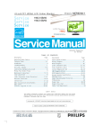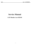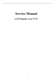
1
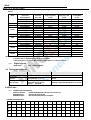
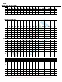
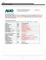
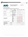
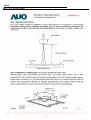
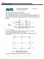
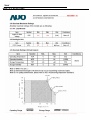
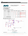
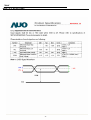
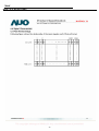
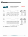
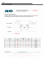
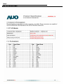
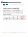
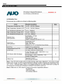
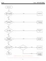
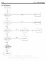
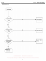
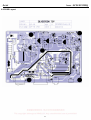
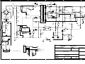
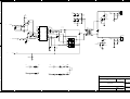
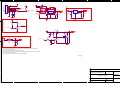
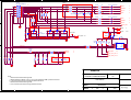
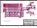
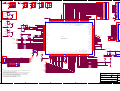
Acer
Acer –LCD-X193HQ
Service Manual
LCD Monitor Acer X193HQ
-0-
1
Table of Contents
Important Safety Notice
.....................................................................................01
01 Product Specification ......................................................................................03
02
Flat Panel Specification ..................................................................................18
03 Exploded Diagram ...........................................................................................37
04 Troubleshooting ................................................................................................39
05 Spare Parts List ...............................................................................................44
06 Schematics and Layouts ..................................................................................45
07
Assembly and Disassembly ...........................................................................48
Appendix : User’s manual
Copyright
Copyright 2006 InnoLux Tech. Corp. Ltd
All Rights Reserved
This manual may not, in whole or in part, be copied, Photocopied, reproduced, translated, or
converted to any electronic or machine readable form without prior written permission of InnoLux
Tech. Corp. Ltd.
Acer X193HQ Service Manual
1
Acer
Acer –LCD-X193HQ
Important Safety Notice
1.
Safety precautions
This monitor is manufactured and tested on a ground principle that a user’s safety comes first.
However, improper used or installation may cause damage to the monitor as well as to the
user.
Warning:
This monitor should be operated only at the correct power sources indicated on the label
on the rear of the monitor. If you’re unsure of the power supply in you residence, consult
your local dealer or Power Company.
Do not try to repair the monitor by yourself, as it contains no user-serviceable parts. This
monitor should only be repaired by a qualified technician.
Do not remove the monitor cabinet. There are high-voltage parts inside that may cause
electric shock to human bodies.
Stop using the monitor if the cabinet is damaged. Have it checked by a service technician.
Put your monitor only in a lean, cool, dry environment. If it gets wet, unplug the power
cable immediately and consult your closed dealer.
Always unplug the monitor before cleaning it. Clean the cabinet with a clean, dry cloth.
Apply non-ammonia based cleaner onto the cloth, not directly onto the class screen.
Do not place heavy objects on the monitor or power cord.
2.
Product safety notice
Many electrical and mechanical parts in this chassis have special safety visual inspections
and the protection afforded by them cannot necessarily be obtained by using replacement
components rated for higher voltage, wattage, etc. Before replacing any of these components
read the parts list in this manual carefully. The use of substitute replacement parts, which do
not have the same safety characteristics as specified in the parts list, may create shock, fire,
or other hazards.
3.
Service notes
When replacing parts or circuit boards, clamp the lead wires around terminals before
soldering.
Keep wires away from high voltage, high temperature components and sharp edges.
Keep wires in their original position so as to reduce interference.
Adjustment of this product please refers to the user’ manual.
2
Acer
Acer –LCD-X193HQ
01 Product Specification
1. General:
Acer X193HQ is designed with LVDS interface and dual (analog and digital signal) input, it featured with embedded
universal AC power supplies and audio input. It’s a green product and meets all ROHS standard. The power button
and display control buttons are on the front of the monitor. The monitors shall automatically to display lower
resolution video modes into 1366x768 full screen display. The image can be adjusted through OSD control.
1.1 Main Features
Features
Specifications
Panel source
M185XW01-V0
Maximum resolution
1366x768 @ 60Hz
Back light system
2 CCFL
Actual Resolution display
WXGA(1366x768)
Pixel pitch
0.3(H) x 0.3(V)
Display area
409.8 ( H ) x230.4 ( V ) , 18.5” diagonal
Contrast ratio
10000:1(ACM ON)
Response time (Tr+Tf)
5ms (typ.)
Viewing angle
85°°(L)/ 85°°(R), 80°°(U)/80°°(D) typ. CR>=10)
Input interface
Analog(D-sub 15 pin)
Digita(DVI-D connector )----option
Audio system
≧ 1W+1W
Power management
Compatible with VESA,EPA,NUTEK,DPMS
Plug & Play
VESA
University AC power supply
YES
OSD language
1.2
For Non-EMEA
For EMEA
English, Deutsch, Español, 简体中文,
简体中文 繁體中文,
繁體中文 Français, Italiano, 日本語
English, Deutsch, Español, Dutch, Russian, Français, Italiano, Finnish
Accessories
Items
VGA cable
DVI
cable
Audio cable
User’s
manual
Warranty card
Quick-start Guide
Description
1.8m
1.8m
1.8m
Multi
Multi
Multi
●
●
●
●
●
●
2. Operation Specifications
The unit should suffer no visible cosmetic damage and should operate with no degradation in display quality during
exposure to the operating conditions and after exposure to the non-operating conditions, in any sequence.
2.1 Environmental conditions
Operating
Specification
Temperature range
5°C to 40°C
Relative humidity
20% to 80%
Altitude
0 to 3657M (12000 ft)
Storage
3
Acer
Acer –LCD-X193HQ
Temperature range
-20°C to 60°C
Relative humidity
5% to 80%
Altitude
0 to 12191M (40000 ft)
2.2 Safety, EMC, Ergonomics and Compatibility Requirements
Items
Description
Safety
EMC
Ergonomics
UL/cUL
CB
TUV/GS
CCC
BSMI
●
●
●
●
●
FCC-B
CE/EMC
CCC
VCCI
C-Tick
BSMI
●
●
●
●
●
●
TCO99
TCO03
Nemko/Erg
o
●
●
Compatibility
Other
Windows 95/98/Me
Windows 2000
Windows XP
Vista
●
●
●
●
Energy Star
Power
Management
●
2.3 Electrostatic Discharge Requirements
Item
Condition
Spec
Contact discharge : +4KV
Electrostatic Discharge
IEC61000-4-2(EN55024)
●
Contact discharge : +8KV
Air discharge : +8KV
●
Air discharge : +15KV
2.4 Reliability
Items
Condition
MTBF
Operating condition is 40°°C
CCFL Life time
Luminance becomes 50%
Spec
Note
≧ 50,000 Hours
Excluding the
LCD, CCFL
≧ 40,000 Hours(min)
Note1
Note1. Display an all WHITE field at mid Brightness and Contrast settings.
3. Electrical and Optical Characteristics and Performance
3.1 Main Power Supply
Items
Condition
Spec
Universal input full range
100~240VAC /50~60Hz
AC Input Current
100Vac
240Vac
1.2A(max)
0.6A(max)
AC Frequency Range
100Vac
240Vac
50Hz – 60Hz
120Vac,cold star,0°C
240Vac,cold star,0°C
30A (max)
60A(max)
DC output full loading
≥75%
+14.2V output
+5.2Vcc output
<400mv
<150mv
AC Input Voltage Range
Inrush Current
Regulator Efficiency
Ripple and Noise
4
Note
Note4
Acer
Acer –LCD-X193HQ
DC Output Voltage and Current
Power consumption
+5.2V audio output
VCC14.2V(13.5~16.3V);
VCC5.2V(4.95~5.45V);
Audio VCC5.2V(4.95~5.45V)
with Audio
<200mv
0.8A(typ.),1.0A(max)
0.8A(typ.),1.0A(max)
0.5A(typ.),0.6A(max)
≤25W
Protection
See Table-1
Power management
See Table-2
Note2.
Before each test, the buck capacitor need to be discharged.
Before each test, it must be 10 minutes at least after the latest test.
Note4. ested by DC loading side parallel with a 47uF/EC and 0.1uF/Ceramic , Capacitors and measured
band-width with DC-20MHz, the sine wave signal that the frequency is 1K Hz input when testing the ripple for the
5V of audio.
Table-1
Protection
OPP(Over power protection)
Condition
Spec
nominal AC input
32W ( min )
Table-2
H-syn
c
Status
Power On
Power Saving
Power Off
V-syn
c
Video
Power
LED
on
on
active
≥ 25W
Blue
off
on
blanked
< 2W
Amber
on
off
blanked
< 2W
Amber
off
off
blanked
< 2W
Amber
--
--
--
< 1W
Off
3.2 Backlight Power Supply
Panel:
AUO M190PW01 V0
Items
Specification
Lamp
2 CCFL
Input Voltage
13.5V~ 16.3 V
Input current
0.8A (Typ.), 1.0A (Max.)
On/Off switch level
5.5V≧
≧Von≧
≧ 2.0 V (on)
-0.3v ≤ Voff ≤ 0.8 V (off)
Brightness PWM duty
Extra PWM duty:18%~100%(DCR);35%~100%(CR);
PWM:High=3.3V(3.0~3.30V),Low=0.0V
CCFL operating Voltage
734Vrms (Typ.),
DCR:1.6 mA (min.); CR:3.0 mA (min)
CCFL Current
7.5mA (Typ.)
8.0mA (Max.)
≧1700 Vrms
CCFL startup voltage
(0˚C)
Operating frequency
40~80 KHz
Protect delay time
> 1 second
Lamp
2 CCFL
3.3 Brightness output
5
Acer
Acer –LCD-X193HQ
The test to verify specifications in this section shall be performed under the following standard conditions
unless otherwise noted.
Temperature
Test pattern
Video Resolution
Video input level
Warm-up time
: 25 ± 5°C
: white
: 1366 x 768
: 700 mV ± 2%
: 30 minutes
LCD Module
BL
≥250 cd/m
M185XW01-V0
2
Set brightness control and also contrast control at maximum, to measure the screen center, the light output
shall ≥ BL cd/m2 (as panel spec)
3.4 White balance
Chromaticity Coordinate
Mode
x
y
Cool
9300K
0.283 ± 0.030
0.297 ± 0.030
Warm
6500K
0.313 ± 0.030
0.329 ± 0.030
Panel While x
Panel While y
User
The test standard conditions refer to Sec 3.3. (Brightness and contrast are under default value)
3.5 Brightness uniformity
The test standard conditions refer to Sec 3.3.
Min. luminance of nine points (backlight )
≡ 75%
Max. luminance of nine points (backlight)
4. Input / Output Signal Specifications
4.1 Video signals
Items
Condition
Specification
Analog RGB signal
Input impedance
= 75 Ohm
0.7Vp-p
Sync
Input impedance
≧ 1k Ohm
TTL level, Separate H/V-sync(+/-)
4.2 Signal Timing
6
Acer
Acer –LCD-X193HQ
Through D-SUB/DVI connectors, this unit can support FH= 31~80 KHz, Fv=55~76Hz, Modes details as
below:
Mode
MAC
VESA
SVGA
MAC
XGA
MAC
VESA
SXGA
VESA
WXGA
Note:
4.2.1
Resolution
(active dot)
640x480@60Hz
640x480@72Hz
640x480@75Hz
[email protected]
720x400@70Hz
800x600@56Hz
800x600@60Hz
800x600@72Hz
800x600@75Hz
[email protected]
1024x768@60Hz
1024x768@70Hz
1024x768@75Hz
1152x870@75Hz
1152x864@75Hz
1280x960@60Hz
1280x1024@60Hz
1280x1024@75Hz
Resolution
(total dot)
800 x 525
832 x 520
840 x 500
864x525
900x449
1024 x 625
1056 x 628
1040 x 666
1056x625
1152x667
1344x806
1328x806
1312x800
1568x909
1600x900
1800x1000
1688x1066
1688x1066
Horizontal
Frequency (KHz)
31.469
37.861
37.500
35
31.469
35.156
37.879
48.077
46.875
49.722
48.363
56.476
60.023
68.700
67.5
60
63.981
79.976
Vertical
Frequency (Hz)
59.941
72.809
75.000
66.66
70.087
56.250
60.317
72.188
75.000
74.55
60.004
70.069
75.029
75.000
75
60
60.020
75.025
Nominal Pixel
Clock (MHz)
25.175
31.500
31.500
30.24
28.322
36.000
40.000
50.000
49.500
57.28
65.000
75.000
78.750
84.520
108
108
108.000
135.000
1280x720@60Hz
1280x800@60Hz
1650x750
1680x831
44.955
49.702
59.940
59.810
74.176
83.500
1366x768@60Hz
1792x798
47.712
59.790
85.500
1. Non-interlace signals only (An interlace signal cannot be display)
2. Please refer to F/W specification for more detail
3. Each frequency of Power Macintosh and Sun Ultra is a reference value
Digital signals
TMDS Signal:
(min) ±200mVpp@24Bit
4.3 Timing requirements
Scan Frequency
Condition
Specification
Horizontal
Sync polarity: (+) or (-)
31 ~ 80 KHz.
Vertical
Sync polarity: (+) or (-)
55-76Hz
Out of range
Excluding
Horizontal 31~80 KHz or
Vertical
55-76 Hz
Message “Input Not Supported” on screen
4.4 DDC data
4.4.1
EDID Standard Compliance
EDID File Format
: VESA’s EDID Standard Version1.0, Revision 12,
EDID Structure
: Version #1, Revision #3.
EDID Data Table
: See the attached table (for example)
X193HQ VGA EDID table
0
1
2
3
4
5
6
7
8
9
A
B
C
D
E
F
0
00
FF
FF
FF
FF
FF
FF
00
04
72
67
00
00
00
00
00
1
00
00
01
03
08
29
17
78
EA
3D
85
A6
56
4A
9A
24
2
12
50
54
BF
EF
90
81
C0
81
00
81
80
81
40
71
4F
3
01
01
01
01
01
01
66
21
56
AA
51
00
1E
30
46
8F
7
Acer
Acer –LCD-X193HQ
4
33
00
9A
E6
10
00
00
1C
00
00
00
FF
00
30
30
30
5
30
30
30
30
30
30
30
30
30
0A
00
00
00
FD
00
37
6
4C
1F
50
0E
00
0A
20
20
20
20
20
20
00
00
00
FC
7
00
58
31
39
33
48
51
0A
20
20
20
20
20
20
00
39
X193HQ DVI EDID table
0
1
2
3
4
5
6
7
8
9
A
B
C
D
E
F
0
00
FF
FF
FF
FF
FF
FF
00
04
72
67
00
00
00
00
00
1
00
00
01
03
80
29
17
78
EA
3D
85
A6
56
4A
9A
24
2
12
50
54
BF
EF
90
81
C0
81
00
81
80
81
40
71
4F
3
01
01
01
01
01
01
66
21
56
AA
51
00
1E
30
46
8F
4
33
00
9A
E6
10
00
00
1C
00
00
00
FF
00
30
30
30
5
30
30
30
30
30
30
30
30
30
0A
00
00
00
FD
00
37
6
4C
1F
50
0E
00
0A
20
20
20
20
20
20
00
00
00
FC
7
00
58
31
39
33
48
51
0A
20
20
20
20
20
20
00
C1
X183H VGA EDID table
0
1
2
3
4
5
6
7
8
9
A
B
C
D
E
F
0
00
FF
FF
FF
FF
FF
FF
00
04
72
68
00
00
00
00
00
1
00
00
01
03
08
29
17
78
EA
3D
85
A6
56
4A
9A
24
2
12
50
54
BF
EF
90
81
C0
81
00
81
80
81
40
71
4F
3
01
01
01
01
01
01
66
21
56
AA
51
00
1E
30
46
8F
4
33
00
9A
E6
10
00
00
1C
00
00
00
FF
00
30
30
30
5
30
30
30
30
30
30
30
30
30
0A
00
00
00
FD
00
37
6
4C
1F
50
0E
00
0A
20
20
20
20
20
20
00
00
00
FC
7
00
58
31
38
33
48
0A
20
20
20
20
20
20
20
00
6A
X183H VGA EDID table
0
1
2
3
4
5
6
7
8
9
A
B
C
D
E
F
0
00
FF
FF
FF
FF
FF
FF
00
04
72
68
00
00
00
00
00
1
00
00
01
03
80
29
17
78
EA
3D
85
A6
56
4A
9A
24
2
12
50
54
BF
EF
90
81
C0
81
00
81
80
81
40
71
4F
3
01
01
01
01
01
01
66
21
56
AA
51
00
1E
30
46
8F
4
33
00
9A
E6
10
00
00
1C
00
00
00
FF
00
30
30
30
5
30
30
30
30
30
30
30
30
30
0A
00
00
00
FD
00
37
6
4C
1F
50
0E
00
0A
20
20
20
20
20
20
00
00
00
FC
7
00
58
31
38
33
48
0A
20
20
20
20
20
20
20
00
6A
4.5 Audio signal
8
Acer
Acer –LCD-X193HQ
Items
Specification
Input impedance
≧ 10K ohm
Frequency response range
200Hz – 20kHz
Signal to noise ratio
≧ 40 dB
Output power
≧ 1.0 W + 1.0 W ( 10%THD )
5. Function Specifications
All the tests to verify specifications in this section shall be performed under the following standard conditions
unless otherwise noted. The standard conditions are:
Temperature
: 25 ± 5°C
Warm-up time
: 30 minutes minimum
Checking display modes
: All the specified modes
5.1 Panel general specifications
5.1.1 General specifications
AUO
M185XW01-V0
Supplier
Model name
Display Area
Pixel Pitch
409.8 ( H ) x230.4 ( V ) , 18.5” diagonal
0.3(H) x 0.3(V)
Display Colors:
16.7 Million (RGB 6-bit + HiFRC)
Number of Pixel
Pixel Arrangement
Brightness
Contrast Ratio
Viewing Angle
Display Mode
Frame rate
Response Time
1366x768 pixels
RGB vertical stripe
2
2
300cd/m (Typ.) 250cd/m (Min.)
1000:1 Typical
85°°(L)/ 85°°(R), 80°°(U)/80°°(D) typ. CR>=10)
Surface Treatment
Lamp
Outline Dimension
Normally White
60Hz
Tr + Tf = 5ms Typical
Anti-glare, Haze = 25%,
Hard coating (3H)
2 CCFL
430.37(W)x254.6(H)x16.5(D)
Typ
5.1.2 LCD module defects
LCD module defects check follow to the IIS.
5.2 Keypad Function
5.2.1 Control buttons on the front bezel
CONTROL KEY
[AUTO]
KEYS FUNCTION
A. When OSD un-displays, press [AUTO] to perform auto-adjustment
B. When OSD displays, press [AUTO] to return to previous level menu
C. When “e Color OSD” OSD displays, press [AUTO] to exit the OSD
9
Acer
Acer –LCD-X193HQ
A. When OSD isn’t shown on screen, press [MENU] to enter OSD interface. The
OSD interface uses “ACER e Color Management” and “User” to instead
“Contrast” and “Brightness” separately. When press “ACER e Color
Management” to show “e Color OSD”, and press “User” to show OSD interface
before. The translations of “ACER e Color Management” and “User” are always
English.
B. When OSD displays, press [MENU] to perform function of menu icon that is
highlight or enter next level menu
[MENU]
A. When “MENU OSD” displays, press these keys to change the contents of an
adjustment item, or change an adjustment value
B. When “MENU OSD” un-displays, if it is with audio, press [►] to show “Audio”
OSD and increase the volume, press [◄] to show “Audio” OSD and decrease
the volume; else it has no use to press these keys.
A. When OSD un-displays, press [e Color] to show “e Color OSD”, and press again
the OSD can not disappear, but the time of “e Color OSD” disappearing is reset
10 second again.
B. When OSD disappear not including “e Color OSD”, press [e Color] to show “e
Color OSD” OSD, the OSD before disappears, but the parameters of it should be
saved
[►], [◄]
[e Color ]
[POWER]
5.2.2
Power on or power off the monitor
Hot Key Operation
HOT KEY OPERATION
FUNCTION
AUTO
e Color
◄
●
FACTORY MODE
►
MENU
POWER
●
ON
Press [e Color ] & [MENU] at the
same time, and then press [POWER]
for DC power on. OSD menu will be
shown with “F” on the left top.
Select “F” for entering factory
mode.
5.3 OSD Structure
The On-Screen Display (OSD) shall be an easy to use icon based menu through keypad OSD buttons or
remote control unit. The unit shall leave the factory with all OSD controls set to their default values.
First
Brightness
Second
ACER eColor
Management
Third
empowering
Control Range
---
Technology
User
Contrast
0 ~ 100
10
Default Value
Standard mode
User mode
50
Text mode
Standard
mode
Graphics
mode
Movie mode
50
50
60
56
Acer
Acer –LCD-X193HQ
Brightness
0 ~ 100
User mode
77
Text mode
Standard
mode
Graphics
mode
Movie mode
44
ACM
Image
Position
Focus
Clock
H. Position
V. Position
Warm (6500K)
Cool (9300K)
Color
User
77
97
77
OFF
-------------
0 ~ 100
Depend on each timing
0 ~ 100
50 ○
1
0 ~ 100
50
0 ~ 100
Depend on each timing
Red
0 ~ 100
80
Green
0 ~ 100
80
Blue
0 ~ 100
80
-----
02. Flat Panel Specification
11
Acer
Acer –LCD-X193HQ
12
Acer
Acer –LCD-X193HQ
13
Acer
Acer –LCD-X193HQ
14
Acer
Acer –LCD-X193HQ
15
Acer
Acer –LCD-X193HQ
17
Acer
Acer –LCD-X193HQ
18
Acer
Acer –LCD-X193HQ
19
Acer
Acer –LCD-X193HQ
20
Acer
Acer –LCD-X193HQ
22
Acer
Acer –LCD-X193HQ
23
Acer
Acer –LCD-X193HQ
24
Acer
Acer –LCD-X193HQ
25
Acer
Acer –LCD-X193HQ
27
Acer
Acer –LCD-X193HQ
28
Acer
Acer –LCD-X193HQ
29
Acer
Acer –LCD-X193HQ
30
Acer
Acer –LCD-X193HQ
32
Acer
Acer –LCD-X193HQ
33
Acer
Acer –LCD-X193HQ
34
Acer
Acer –LCD-X193HQ
35
Acer
Acer –LCD-X193HQ
36
Acer
Acer –LCD-X193HQ
37
Acer
Acer –LCD-X193HQ
38
Acer
Acer –LCD-X193HQ
40
Acer
Acer –LCD-X193HQ
41
Acer
Acer –LCD-X193HQ
42
Acer
Acer –LCD-X193HQ
43
Acer
Acer –LCD-X193HQ
45
Acer
Acer –LCD-X193HQ
03
Exploded
Diagram
3.1 Screw List
Item
Part No.
Description
Qty
1
509146305300R
2
509000000700R BOLT,#4-40x11.8,Ni ROHS
3
509112612500R
4
509216608110R
5
509212606110R
6
509112308100R
SCREW,P,CROSS
W/WAS,M3*5,Zn ROHS
SCREW P T4*12 Zn-BLK
ROHS
SCREW,F,CROSS,M4*8,Zn,
ROHS
SCREW,F,CROSS,T4*6,Zn,
ROHS(5.8~6.2)
SCREW,P,CROSS,T.T-3*8,Z
n,ROHS
46
Fixed
T(kg*cm)
Remark
Power Board to
3
4.5~5.0
2
4.0±0.5
D-SUB CON*2
3
8±0.5
Hinge to Stand
4
6.5±0.5
Hinge to backcover
10
6.5±0.5
Base Plate to Base
1
3.0~4.0
Chassis*3
Back cover to Front
bezel
Acer
Acer –LCD-X193HQ
3.2 . LCD Exploded drawing (All)
47
Acer
Acer –LCD-X193HQ
04 Troubleshooting
4.1 No Power & LED Off
No power
Check primary
rectifier voltage
Check
circuit if
short
Check IC802,
C805, T801,
Check F801, P801,
RT801, D801
Check pin2 of
IC802 voltage
about 16V
CheckC815,D806,
Check primary OVP,
OLP and secondary
feedback, OVP
Check pin1 of IC802
voltage about 9.0V
circuit
Check R803, R807,
R824, R825,R812
Check pin1 of IC802
voltage is below
1.5V
END
48
Acer
Acer –LCD-X193HQ
4.2 Unstable Power
Unstable power
Check sampling
Circuit
Check R811,
R818, R810,
R811, R818,
R810, R825,
Check the C
pin voltage of
Check the R
pin voltage of
IC803 about
Change IC803
IC803 if 3V
Check
Check pin2
of IC802
voltage is 16V
Check D806 , C815 is hort
Change
D803
Check pin1 of
IC802 voltage below
Change R803, R 807
R824, R825, R812
HRN LVDS FFC *1
1.4V
END
49
Acer
Acer –LCD-X193HQ
4.3 DC output voltage is unstable
Output voltage unstable
Check Vbe of
Q801below 0.3V
Checkcircu
it if
Check ZD801,
D803, D805
Check Q801, Q802
Check
reference
voltage
Check Pin R of
IC803 voltage
about 2.5V
Check R832,, IC801,
Check R822,
R823.R825
Check feedback
circuit
Check
Vpin2.4of IC801
about 1V
Check Vpin6 of
IC801have output
Change IC
END
50
CheckR815, c814,
R816
Acer
Acer –LCD-X193HQ
4.4 No Raster
No raster?
Yes
LED Blue?
Yes
Backlight can’t
be turned on.
Yes
Is there 16Vdc
voltage on pin9
of IC501?
No
Check power
supply
Yes
Is there high-level
voltage on pin8 of
IC501?
No
Is Ok R510?
Yes
Check I/F
board
No
Yes
R501 open
Are connected rightly
CN501, CN502, CN503
and CN504?
Connecting the output
connector again
No
Yes
Is there instantaneously
pulse wave on pin14,
pin11 of IC501 at the
moment of restart?
No
Is Ok IC501?
Yes
U501, U502 fail
No
IC501 fail
Yes
Is T501, T502
ok?
No
T501, T502 fail
Yes
END
Check feedback circuit
Isen,Vsen.(pin 1.2)
pin2,D508,D509.)
51
Acer
Acer –LCD-X193HQ
4.5 Black Screen
52
Acer
Acer –LCD-X193HQ
4.6. White screen
53
Acer
Acer –LCD-X193HQ
4.7 Bad Screen
54
Acer
Acer –LCD-X193HQ
05 Spare parts List
ACER PART
NO.
DESCRIPTION
UNIT PRICE
(US$)
ET.LEH0C.024
55.LEH0J.001 791931300702R
PCBA,I/F BOARD,W/SPK,LE18K3-712 ROHS
6.20
1
19.LEH0J.001 791931400700R
PCBA,P/I BOARD,W/SPK,LE18K3-712 ROHS
10.00
1
55.LAU0J.002 790061500000R
PCBA,KEYPAD BOARD,LE1983-X10 ROHS
1.00
1
50.LEH0J.001 430300802230R
HRN ASSY 2x4P to 8P 190mm UL1571#28
0.29
1
50.LEH0J.002 430303001970R
HRN LVDS FFC 30P 147MM
0.50
1
50.LBQ0J.001 453010100380R
CABLE,D-SUB 15P MALE 6FT BLACK/BLUE,
ROH
1.00
1
50.L63VF.003 453030300120R
CABLE AUDIO 1P 6FT BLACK/GREEN
CP03B06P0
0.40
1
50.LA10J.003 453030300370R
CABLE,DVI-D 18+1P MALE 6FT BLACK ,
ROHS
1.30
1
27.L46VF.005 453070800230R
PWRCORD 5A/250V BLK 6FT
UK3Gx.75mm(SP60/
1.40
1
42.LEH0J.001 501020225700R
COVER HINGE,BLACK RIGHT,LE18K3
0.05
1
42.LEH0J.002 501020225701R
COVER HINGE,BLACK LEFT,LE18K3
0.14
1
60.LEH0J.003 701000011703R
ASSY,CHASSIS,ALL,AUO ,LE18K3
1.60
1
60.LAU0J.005 714011201500R
ASSY,STAND LE1990
1.80
1
60.LAS0J.004 714020010600R
ASSY,BASE, LE1990 ROHS
1.50
1
60.LEH0J.004 714030020501R
ASSY, BEZEL,BLACK,INL,LE18K3
3.00
1
114.00
1
OEM PART NO
LK.18005.002 631102092170RA LCP 18.5" M185XW01-V1-0A(A)(AUO)ROHS
55
Acer
Acer –LCD-X193HQ
06 Schematics and Layouts
6.1 PI BD Layout
56
Acer
Acer –LCD-X193HQ
6.2 PI BD Layout
57
Acer
Acer –LCD-X193HQ
6.3 IF BD Layout
58
Acer
Acer –LCD-X193HQ
6.4 IF BD Layout
6.2 Switching Mode Power Supply circuit
59
5
4
3
2
C820
4700P Y1
C805
68u/450V
7
2
2
3
1
1
Q801
MMBT4401
R835
1.0R 1/2W
F802
+5V
SB540
4A/125V
1
6
1
R817 D806
6R8 A02
2
9
C812
R829
4.7R
C826
1n 500V
R825
2.7M
R839
150R NC
C
D808
1N4003
R816
6R8
1
C816
0.1u 100V
MEB
LTV817M
NC 9.1V
ZD806
D809
C
SN4148
A
C818
47u/25V
C822
C821
2200P Y1
250V
250V
C801-1
R814
1K
10u/16V
R
IC803
TL431
C824
R818
3.3K
1
2
R841
2
3
R815
1K
2 1
1
2
1
5
8
7
1
R810
5K1 1%
1
1
2
4
2
2
S
S
S
S
6
1
R812
2 1
2
C817
0.1u 50V
2
0.33u X2
F801
2A/250V
C
10K 1%
275V C804
B
1
D
IC802
TOP258P
C819
NA
IC801
2
51K 1%
R811
1
R813
10K
M
4
RT801 R830
330K
5R
R840
NC
+ C709
220u/16V
2
2
R809
150R
1
R821
330K
2
1
C815
47u/25V
20mH
330K
Audio5V
R822
10K
5
C
R820
C814
220uF 10V
680u 10V
680u10V
2
1
2
4
C823
2
10
1
3
2
R824
2.7M
1
2
L801
D
3
R819 200R
1
1
4
L8035uH
D807 SB540
D807-1
3
ZD801
9V1
Q802
MMBT4401 NC
ZD802
14V NC
8
D804
MUR1100
1
R823
100R 1W
2
R807
2.7M
10K NC
C811
C808
1n 500V 470uF 25V
R832
NC
2
R806
4.7R
1 2
2
-
2
1
3
R837
24K
4n7/1KV
C803
R833
R838
24K
+
2
24K
68ohm
+14V
D805
SB5150
1
1
68ohm
12
2
+ 1
2.7M
11
2
R803
BL4-06
C802
1n 500V
1
R836
R842
D801
T801
SPW-093
400V
R843
D
R802
10R
1 2
1
NC
B
NC 10u/16V
PGND
C806
1000P Y1
NC 1000P/250V Y2
CN801
1
2
N
L
SW801
SW DPST
3
P801
A
AC IN
TO SCALER BD CN101
1
2
3
4
5
6
7
8
60mm 8P
InnoLux
+5V
Document Number :
ON/OFF
BRIGHTNESS
VOL
Audio_MUTE
C827
NA
C825
0.1/50V
3
3
4
4
CHECK BY :
Power SCH
NA
SHEET
4
APPRO BY :
SIZE :
A4
TITLE :
C829
2008-05-21
DATE :
5
Acer18.5
3
2
OF
2
4
DRAWN BY :
Rev :
V01
1
A
5
4
3
2
1
D
OL2
VIN
C516
10p/3KV
VIN
C510
C509
2.2u/25V NC
R520
20K
3
C522
1
R502
100K
C502
220p/50V
1
R503
100K
OV21
OV2
OV1
LI1 2
LI1
GND
LI2 3
LI2
BG
14
VCC
13
SW
12
TG
11
C504
2.2u/16V
4
COMP
5
FT
C
R505
105K 1%
BRIGHTNESS
REF
R526
NC
R504
10K
C505
220p/50V
C520
3300p/50V
680pF/50V
L<2.cm
16 OV1
C508
1u/16V
15
W=2.0mm
T501
2
3
FSET
7
BOSC
BT
10
8
DBRT
VIN
9
C514
NC
R506
10
REF
6
8
C513
0.1/50V
5
6
7
C
SPW-078
4100-D02
C506
0.047/50V
U501
OL1
IC501
MP1009
1
8
2
7
3
6
4
5
C517
10p/3KV
R507
10
C507
0.1/50V
R508
100
1
H
2
L
CN501
R516
390 1% R518
10K 1%
LV1
2
D
Q502
MMBT4401
C503
3300p/50V
2
R519
20K
L
2
3
ON/OFF
2
2
C511
C512
2.2u/25V NC
Q501
MMBT4401
H
2
CN504
4100-D02
R515
R517
390 1% 10K 1%
LV2
R501
100K
1
C523
C521
3300p/50V
680pF/50V
AP9971NN
VIN
+14V
+
B
B
C501
470u/25V
LI1
OL1
R509
2K
LV1
OV1
D503
SN4148
R512
2K
R511
10K
D501
SN4148
REF
LI2
OL2
LV2
OV2
R510
2K
D504
SN4148
R514
2K
R513
10K
D502
SN4148
InnoLux
Document Number :
A
SIZE :
doc
APPRO BY :
A3
TITLE :
CHECK BY :
Inverter SCH
DATE :
SHEET
5
4
3
2
DRAWN BY :
2008-05-21
3
OF
4
Rev :
01
1
A
5
4
3
2
1
VCC5V
VCC5V
GND
NC
C101
+
100u/16V/NC
R101
0/NC
C104
R0805 0.1/16V
Note 6
PAD
U102
LD1117AL-1.8V
+3.3V
+3.3V
3
+3.3V
5
4
VIN
+1.8V
2
VOUT
+1.8V
5
D
4
PAD
+
C106
0.1/16V
+
C175
NC
R199 100
10P 2.0mm
D101
SSM24APT
DIO--SMA
DCR_CONTROL 5
Note 5
R104 0/NC
Note 3
U101
LD1117AL-3.3V
3 VIN VOUT 2
1
BRIGHTNESS 5
VOLUME 5
MUTE
5
Note 2
R110
10K
ADJ
2
CCFL_ON/OFF
C102
100u/16V
C105
0.1/16V
C103
22u/25V
1
D107
BAT750-LF/NC
3
1
DVI5V
ADJ
VGA5V
+3.3V
1
2
3
4
5
6
7
8
9
10
C160
D
To Power/Inverter
Board
CN101
C107
0.1/16V
GND
+3.3V
GND
GND
R102
10K
R103
10K
CCFL_ON/OFF
3
R105
4K7
1
Q103
PMBT3904
Q101
AP2305GN
2
3
VCC5V
C
GND
VLCD
R112
51/NC
R0603
1
C108
0.1/16V
R109
100K
3
Note 4
VLCD
C
5
0.1/16V
2
R106
100K
100u/16V
5 CCFL_ENABLE
1
5 PANEL_ENABLE
R113
0/NC
R0805
C111
0.1/16V/NC
C112
1u/16V
ZD107
R108
47K
Q102
2N7002/NC
2
Q104
PMBT3904
C110
1
GND
R107
100K
VCC_ESD
3
VCC_ESD
3,4
2
ZD101
6V2/NC
C109
+
VCC5V
6V2
GND
GND
GND
B
Note:
1. CN101 is no locked packgae for normal model.CN101 is locked packgae for special model(Dell).
2. D101 must be co-layed with R101
3. U101 must contain TO263, TO252 and SOT223 package
4. ZD101 must be co-layed with R113. ZD101 is used for ESD back drive.Reserved C111 for EMI issue.
5. U101 must be co-layed with R104
6. Using embedded 3.3 to 1.8 LDO NC U102 and C106 for NT68667
B
Anxing
InnoLux
Document Number :
A
SIZE :
NT68667 COMMON BOARD
TITLE :
POWER (DC TO DC)
5
4
3
2
CHECK BY :
2008-06-23
DATE :
SHEET
APPRO BY :
A3
2
OF
5
DRAWN BY :
Rev :
V03
1
A
5
1
75 1%
0
R114
75
C113 0.047u/16V
0
R115
75
C114 0.047u/16V
0
R116
75
C115 0.047u/16V
C116
10p/50V/NC
R159
C117
C118
10p/50V/NC 10p/50V/NC
470 1%
R0603
C134 0.047u/16V
R122
75
C119 0.047u/16V
R123
75
C120 0.047u/16V
R124
75
C121 0.047u/16V
VGA_DET
2
D103
BAV99
1
2
D104
BAV99
1
2
3
D102
BAV99
1
VCC5V
5
GREEN+
5
BLUE+
5
SOG
5
RED-
5
GREEN-
5
BLUE-
5
D105
BAV99
1
VGA_DET
R126
0/NC
VCC_ESD 2,4
1
C125
0.1/16V/NC
2
C124
0.1/16V/NC
5
D106
BAV70
VGA5V
2
VCC5V
2,4,5
C
C128
0.1/16V
3
C123
0.1/16V/NC
VCC_ESD
D
VGA5V
Note 4
C127
0.1/16V/NC
C122
0.1/16V/NC
RED+
VGA_DET
3
3
C126 0.1/16V
6V2
ZD102
2
RB101
R0603
RB102
R0603
RB103
R0603
3
Note 3
GND
C
R121
R120 0/NC
17
16
0
15
R119
14
75 1%
D
75 1%
13
2
Note 2
R118
12
CN102
DZ11AA1-H5W6-4F
R
1
6
G
2
7
B
3
8
VGA5V
4
Note 1
9
5
10
3
R117
11
4
GND
GND
R127
4K7
R131
R132
VGA_SCL
VGA_SDA
2K2
33p/50V
33p/50V
C130
GND
R136
GND
C129
2K2
R135
6V2
R129
10K
U103
R130
1K
8
7
6
5
100
100
VCC
WP
SCL
SDA
A0
A1
A2
GND
AT24C02BN
R133
R134
ZD106
6V2
6V2
ZD105
ZD104
ZD103
B
6V2
FB101
120Ω
R128
4K7
1K
1K
HSYNC
VSYNC
5
5
WP_EDID
GND
4,5
DDC_SCL_VGA 5
DDC_SDA_VGA 5
Note 5
C131
33p/50V/NC
1
2
3
4
B
C132
33p/50V/NC
InnoLux
Document Number :
A
4
3
CHECK BY :
2008-06-23
DATE :
SHEET
APPRO BY :
A4
NT68667 COMMON BOARD
TITLE :
VGA-INPUT
Note:
1. R120 is reserved for Samsung model.
2. R0603 package for Bead. C116,C117,C118 are reserved for EMI or performance issue.
3. C122,C123,C124,C125 are reserved for ESD or EMI issue.
4. R126 is reserved for Samsung model.
5. C131,C132 are reserved for tuning performance issue.
5
SIZE :
3
OF
2
5
DRAWN BY :
Rev :
V03
Anxing
1
A
5
4
3
2
1
VCC5V
DVI5V
CN201
DVI-D_CON
DVI_RX1DVI_RX1+
R203
R204
10
10
DVI_RX0DVI_RX0+
R205
R206
10
10
DVI_RXC+
DVI_RXC-
R207
R208
10
10
SCL
SDA
VS
6
7
8
DVI_SCL
DVI_SDA
5V
GND
HP
RX4RX4+
GND
RX3RX3+
RX5RX5+
14
15
16
4
5
11
12
13
20
21
RX2RX2+
5
5
RX1RX1+
5
5
RX0RX0+
5
5
RXC+
RXC-
5
5
R209
R210
R215
0/NC
R211
4K7
D201
BAV70 C201
0.1/16V
R212 R213
4K7 10K
U201
R214
1K
8
7
6
5
100
100
VCC
WP
SCL
SDA
A0
A1
A2
GND
1
2
3
4
AT24C02BN
WP_EDID
3,5
DDC_SCL_DVI 5
DDC_SDA_DVI 5
DVI_DET
5
DVI_DET
HPD_DVI
GND
C
R217
10K
R218
100
HPD_DVI
3
6V2
C213 0.1/16V
6V2
DVI5V
Q201
PMBT3904/NC
1
2
C204
0.1/16V/NC
C206
0.1/16V/NC
C208
0.1/16V/NC
C210
0.1/16V/NC
2
Note 2
ZD202
D209
BAV99/NC
1
0.1/NC
C211
0.1/16V/NC
DVI5V
ZD204
2
3
3
3
2
D207
BAV99/NC
1
C209
0.1/16V/NC
2
D210
BAV99
1
6V2
D205
BAV99/NC
1
D208
BAV99/NC
1
C212
2
C207
0.1/16V/NC
2
3
C205
0.1/16V/NC
2
D206
BAV99/NC
1
ZD203
2
D203
BAV99/NC
1
D204
BAV99/NC
1
3
3
C203
0.1/16V/NC
2
3
3
2
D202
BAV99/NC
1
3
DVI5V
DVI5V
ZD201
D
Note 1
DVI_DET
HPD_DVI
B
2,3,5
1
10
10
2
R201
R202
2
VCC5V
3
DVI_RX2DVI_RX2+
6V2
C
1
2
3
9
10
19
17
18
22
23
24
RX2RX2+
GND
RX1RX1+
GND
RX0RX0+
GND
RXC+
RXC-
C202 0.1/16V
D
DVI5V
VCC_ESD
R219
4K7/NC
HPD_CTRL
5
HDCP Function
GND
B
VCC_ESD 2,3
GND
InnoLux
Note:
1. R215 is reserved for Samsung model.
2. R218 is reserved for some model.
Document Number :
4
3
CHECK BY :
2008-06-23
DATE :
SHEET
APPRO BY :
A4
NT68667 COMMON BOARD
TITLE :
DVI-INPUT
A
5
SIZE :
4
OF
2
5
DRAWN BY :
Rev :
V03
Anxing
1
A
GND
GND
C138
22u/25V
GND
+
RXO0RXO0+
RXO1RXO1+
RXO2RXO2+
C153 0.1/16V
60Ω
1
CN107
FFC-CON/NC
Note8
C135 0.1/16V
C139
1u/16V
Note 1
C144 0.1/16V
60Ω
Note 1
FB106
2
+1.8V
RXE1RXE1+
RXE2RXE2+
RXECRXEC+
RXE3RXE3+
VCC5V
R161
2K2/NC
Q106
PMBT3906/NC
1
LED_B
DVDD_3V3
LED_B_C
R162
10K/NC
3
R163
330/NC
R0603
LPIN6
LPIN5
VSO
HSO
GND
PANEL_ENABLE 2
R164
R0603
2
LED_A_C
100/NC
Note7
30
29
28
27
26
25
24
23
22
21
20
19
18
17
16
15
14
13
12
11
10
9
8
7
6
5
4
3
2
1
RXOCRXOC+
RXO3RXO3+
RXE0RXE0+
GND
Note 2
2
D
+
Note 1
FB107
3
VAA_3V3
+3.3V
C154 0.1/16V
C150
22u/25V
C143 0.1/16V
60Ω
C156 0.1/16V
+
Note 1
FB104
C155 0.1/16V
C142 0.1/16V
60Ω
C141
22u/25V
PVCC_3V3
C159 0.1/16V
Note 1
FB102
C152 0.1/16V
+3.3V
4
AVCC_3V3
+3.3V
C137 0.1/16V
5
DVDD_3V3
+3.3V
VLCD
30
29
28
27
26
25
24
23
22
21
20
19
18
17
16
15
14
13
12
11
10
9
8
7
6
5
4
3
2
1
RXO0RXO0+
RXO1RXO1+
RXO2RXO2+
RXOCRXOC+
RXO3RXO3+
VLCD
R150
66
67
68
69
70
71
72
73
74
75
76
77
78
65
PA0/PWM2
PA2/PWM4
PA1/PWM3
RSGA2P/T7P
RSGA2M/T7M
RSGA3P/TCLK2P
RSGA3M/TCLK2M
RSRA1P/T6P/RSBB0P
RSRA1M/T6M/RSBB0M
RSRA2P/T5P/RSGB0P
RSRA2M/T5M/RSGB0M
RSRA3P/T4P/RSRB0P
RSRA3M/T4M/RSRB0M
80
81
82
79
RSBB1P/T3P
DGND/CGND
RSBB1M/T3M
RSBB2P/TCLK1P
84
85
83
RSBB3P/T2P
RSBB3M/T2M
86
88
87
RSGB1P/T0P
90
91
92
93
94
95
96
97
98
89
SP
DVDD
RSGB2P
RSGB2M
RSGB3P
RSGB3M
RSRB1P
RSRB1M
RSRB2P
RSRB2M
99
RSRB3P
100
RSRB3M
62
RSCLKAM/V7
61
SPI_CLK
RSCLKAP/V6
60
108
PD4
RSBA3M/V5
59
109
GND
RSBA3P/V4
58
110
GPO1
RSBA2M/V3
57
111
AD0/GPO2
RSBA2P/V2
56
112
AD1/GPO3
RSBA1M/V1
55
VSO
R147
100
113
INT_VSO/GPO4
RSBA1P/V0
54
HSO
R148
100
114
INT_HSO/GPO5
DVDD
53
115
CVDD
CVDD
52
116
GPO6
DVDD
51
117
PWMA/GPO7
118
PWMB/GPO8
119
CVDD
120
U105
RXO0RXO0+
RXO1RXO1+
RXO2RXO2+
RXE1RXE1+
+1.8V
Note6
DVDD_3V3
50
IICSCL
49
IICSDA
PD5
48
E2P_WP
PC0*
PB4*/DVI_SCL0
47
121
PC1*
PB5*/DVI_SDA0
46
122
PC3/PWM0
PLL_VDD
45
1K
123
PC4/PWM1
GND
44
PC5
PLL_GND
43
TOUTP/VSYNCI1
42
VSYNC
3
HSYNC
3
41
40
PA6*/PWM8*
39
GND
C151
0.1/16V
LED_G
KEY2
DVDD_3V3
R171
R138
10K/NC 4K7
GND
A
Note:
1. Each bypass capacitor (0.1u/16V) must be respectively closed to pin that is DCpower input of scaler IC.
2. LED blue driving circuit is reserved for BenQ model.
3. Bypass capacitor C167,C168,C169,C170,C171,C172,C173 are for ESD and EMI issue. ESD component
EP101,EP102,EP103 are for GPIO direct driving LED.
4. CN104 is no locked packgae for normal model.CN104 is locked packgae for special model(Dell).
5. RL111,RL112,RL113,RL114 are reserved for some panel spec.
6. CN103 is no locked packgae for normal model.CN103 is locked packgae for special model(Dell).
7. Connector CN105 for 15.6w&18.5w B type single LVDS input panel
8. DIP Connector CN107 for special LVDS input panel
9. U108 can be cost down if use the 68667 which have internal Flash
RX2+
RX2RX1+
RX1RX0+
RX0RXC+
RXC-
AVCC_3V3
3
3
3
3
3
3
3
BLUE+
BLUESOG
GREEN+
GREENRED+
RED-
E2P_WP
IICSCL
IICSDA
B
R145
R142
R143
1K
100
100
8
7
6
5
VCC
WP
SCL
SDA
C140
0.1/16V
A0
A1
A2
GND
AT24C16AN
WP_EDID
3,4
DVDD_3V3
HPD_CTRL
R178
VAA_3V3
1K
R180
1K
R216
1K
R125
1K
1
2
3
4
GND
VCC5V
4
R152
10K
DDC_SCL_VGA 3
R179
10K
AC_DET
RX
TP4
TX
TP5
R144
20K
KEY1
DVI_DET
4
VGA_DET
3
A
InnoLux
Document Number :
SIZE :
NT68667 COMMON BOARD
APPRO BY :
A2
TITLE :
CHECK BY :
Scaler
2008-06-23
DATE :
SHEET
5
R137
4K7
U106
PVCC_3V3
4
4
4
4
4
4
4
4
2
DVDD_3V3
DDC_SDA_VGA 3
C173 0.1/16V
C172 0.1/16V
C171 0.1/16V
C170 0.1/16V
5P35V
EP103
5P35V
C169 0.1/16V
EP102
5P35V
C168 0.1/16V
EP101
To Keypad
Board
LED_B
LED_GREEN
POWER
KEY1
ADC_KEY1
ADC_KEY2
LED_B
LED_A
CON--PI-AL230C
C136
0.1/16V
+
DCR_CONTROL
470 1%
R0603
OTHER_KEY
ENTER&PLUS
EXIT/MINUS
LED_BLUE/OTHER_KEY
LED_AMBER
VLCD
DDC_SDA_DVI 4
C133
22u/25V
R146
Note 3
1
2
3
4
5
6
7
8
C167 0.1/16V
CON--CLX-CI0108P1VDL-1
CN104
2x4P 2.0mm
0
C
DDC_SCL_DVI 4
Note4
R175
100K
LPIN6
LPIN5
0/NC
0/NC
0/NC
RL114
R0603
2
PA5*/PWM7*
PA4*/PWM6*
PA3/PWM5
HSYNCI1
PA7*/PWM9*
RL111
RL112
RL113
38
37
36
PB6*/DDC_SCL1
35
PB7*/DDC_SDA1
34
RIN1+
GIN1-
RIN125
24
23
GIN1+
22
BIN1-
BIN1+
SOG1I
21
20
19
PGND
18
PVCC
17
AVCC
RXC-
REXT
16
15
14
RXC+
13
RX0-
RX0+
AGND
12
11
10
AGND
9
DVDD_3V3
RX1-
C158
22p/50V
RX1+
X101
12MHz
1
C157
22p/50V
8
B
2
AVCC
1
PB2/ADC2/INT0
OSCO
1M
P30/RXD
128
R160
33
OSCI
P31/TXD
PB0/ADC0
127
32
126
31
1K
PB3/ADC3/INT1
R158
30
PB1/ADC1
ADC_KEY2
PD6
125
PC2
124
1K
29
1K
R157
ADC_GNDA
R156
ADC_KEY1
28
KEY2
27
R155
ADC_VAA
LED_B_C
26
1K
2 CCFL_ENABLE
NT68667/NT68670B
RX2-
1K
RXE2RXE2+
RXECRXEC+
RXE3RXE3+
DVDD_3V3
SCL/P34
1K
R153
30
29
28
27
26
25
24
23
22
21
20
19
18
17
16
15
14
13
12
11
10
9
8
7
6
5
4
3
2
1
RXOCRXOC+
RXO3RXO3+
RXE0RXE0+
SDA/P35
R151
R154
MUTE
RSGA1P/VCKI
SPI_SI
7
2
SPI_SO
6
VOLUME
63
5
2
+1.8V
CN103
FFC-CON/NC
64
RX2+
2 BRIGHTNESS
R174
R173
R0603
CON--PI-AL230C
Note6
RSGA1M
4
R170
100/NC
10K
DVDD_3V3
RSCLKBP/T1P
107
WP_FW
RSCLKBM/T1M
106
RSGB1M/T0M
105
SDI
SCK
D
GND
CGND/DGND
GND
R169
10K
10K/NC
R168
330
R0603
SDO
GND
LED_G_C
10K
LED_G
2 SDO
1 SCS
6 SCK
5 SDI
PM25LV010A-100SCE
10K
2
R176
2K2
1
3
Q108
PMBT3906
R191
1K
SO
CS#
SCK
SI
SPI_CE
DVDD
R192
10K
VCC
HOLD#
WP#
GND
PC7
104
3
VCC5V
C
8
7
3
4
WP_FW
103
SCS
2
100/NC
U108
R196
R167
R0603
GND
RSBB2M/TCLK1M
R189
R190
10K/NC 10K
LED_G_C
DGND/CGND
102
PC6
C165
0.1/16V
10K
LED_A
DVDD_3V3
R166
10K
3
R165
330
R0603
LED_A_C
RSTB
1
R172
2
R177
2K2
Q107
PMBT3906
101
CON--HR-200PHD2X15ST
VCC5V
CN105
FFC-CON
4
3
2
5
OF
5
DRAWN BY :
Rev :
1
V03
Anxing
Acer
Acer –LCD-X193HQ
7.0 Assembly and Disassembly
Sequence
S1
Ite m
P la c e p a n e l
S2
A s s e m b le
fro n t b e z e l
S3
P la c e
c h a s s is
P h o to
P roc e dure s
(1 ).T a k e p a n e l o u t o f b o x a n d p la c e it o n
th e fo a m .
(2 ).T e a r o p e n th e P E b a g a n d p u t it in
th e d e s ig n a te d c a rto n .
(3 ).P la c e p a n e l o n th e fo a m lik e th e
a tta c h e d p ic tu re .
R e m a rk :D o n o t to u c h th e la m p c o rd a n d
p la c e th e s u rfa c e o f p a n e l d o w n s id e s o n
th e c u s h io n .
P /N
D e s c rip tio n
6 3 1 1 0 2 0 9 1 8 5 0 R A U O V 0 -0 0 P a n e l
1 .R e ve rs e th e p a n e l b y 1 8 0 d e g re e u s in g
b o th h a n d s ,p u t th e s u rfa c e o f p a n e l
d o w n s id e s a n d m a k e s u re F F C in te rfa c e
is c lo s e r to o p e ra to r.
2 .P a s te tin fo il o n th e p o s itio n w h ic h re fe rs
714030020501R
to a tta c h e d p ic tu re ,in o rd e r to c o ve r th e
g a p in th e p a n e l c o m p le te ly.
R e m a rk :M a k e s u re th e fixe d jo b is
fin is h e d p ro p e rly a n d la m p w ire is c lo s e r
to rig h t h a n d ;M a k e th e tin fo il s m o o th in
th e c o rn e r o f p a n e l.
A S S Y,
B E Z E L ,B L A C K ,IN L ,
LE18K3
In s e rt p o w e rb o a rd in to th e d e s ig n a te d
lo c a tio n o f c h a s s is ,lik e th e a tta c h e d
P ic tu re
A S S Y ,C H A S S IS ,W /
O S P K D V I,A U O
,L E 1 8 K 3
52
701000011700R
Acer
Acer –LCD-X193HQ
Assembly and Disassembly (continue)
FFC socket
S4
Keypad cable
socket
Insert FFC
cabel into
mainboard
(1).Insert FFC wire into its relevant
interface of mainboard properly like
attached picture1.
(2).Insert the short keypad into its
relevant interface like picture
(2).Put the fixed mainboard in the right
position.
430303001970R
HRN LVDS FFC
30P 147MM
link main board
and power
S5
1. Link power board and main board ,and
make sure the cable is in the correct
PCBA,P/I
position
791931400700R BOARD,W/SPK,LE
2.put the main board into the chassis
18K3-712 ROHS
and make the FFC cable is OK , as
picture
link power
board and
main board
1
S6
2
3
Fix board
4
Fix 4pcs M3*5 screw into the power
board and main board as picture
53
PCBA,I/F
791931300702R BOARD,W/SPK,LE
18K3-712 ROHS
Acer
Acer –LCD-X193HQ
Assembly and Disassembly (continue)
make sure keypad
cable into the
interface
S7
S8
S9
Pack keypad
cable
Twist
Hexagonal
screws
Assemble
chassis
keypad cable
through chassis
1
2
3
4
Insert the keypad cable into the chassis
as picture
HRN ASSY 2x4P to
430300802230R 8P 190mm
UL1571#28
(1). Handle hexagonal screws and
electric opener
(2). Twist screw in the interface like the
attached Picture1.
(3). Place cushion on the designated
location after iron frame is taken away.
put the chassis into the position of front
bezel and make sure the FFC cable is
OK , as picture
54
ASSY,CHASSIS,W/
701000011701R O DVI,AUO
,LE18K3
Acer
Acer –LCD-X193HQ
Assembly and Disassembly (continue)
S10
Insert the FFC cable into the interface of
HRN LVDS FFC
430303001970R
panel as picture
30P 147MM
Insert FFC
cable
insert FFC
bl
S11
S12
Insert light
cable
Insert speaker
cable
1)Insert 4pcs light wire into the relevant
position
2) put the balance light wire to the
position as picture
Insert the speaker cabler into the
SPEAKER 2W 8Ω
interface of power board as picture, make
618100200360R 290&240mm R/G/B
sure the red cable in right and the green
W/CASE
cable in left
55
Acer
Acer –LCD-X193HQ
Assembly and Disassembly (continue)
Picture 1 left
speaker
S13
Assemble
speaker
picture 2 right
speaker
Put the right and left speaker into the two
SPEAKER 2W 8Ω
position of chassis , remark : put the
speaker with green cable to left ,and put 618100200360R 290&240mm R/G/B
the speaker with red cable to right , you
W /CASE
can find picture 1and picture 2
picture
1
S14
Insert keypad
cable
1) Link keypad cable and keypad as
picture1
2) put the ksypad into the interface of
front bezel as picture 2
PCBA,KEYPAD
790061500000R BOARD,LE1983X10 ROHS
Check if back cover is fixed properly
BACK COVER,W /O
501020225702R DVI SPK
,BLACK,LE18K3-AU
picture
2
S15
Fix back
cover
56
Acer
Acer –LCD-X193HQ
Assembly and Disassembly (continue)
S17
S18
Assemble
cover hinge
Packing
1
2
COVER
Put the right and left cover hinge into the
501020225700R HINGE,BLACK
related position as picture
RIGHT,LE18K3
(1)Release monitor to the packing line
(2)Put monitor into carton like the
attached picture
57