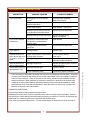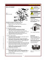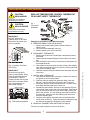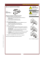
1
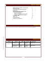
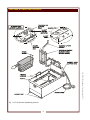
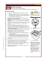
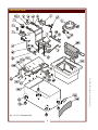
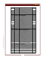
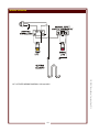
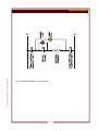
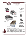
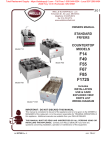
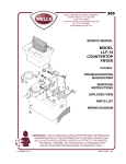
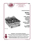
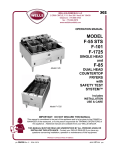
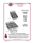
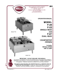
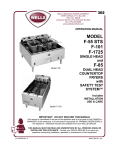
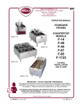
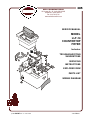
305
WELLS MANUFACTURING
10 Sunnen Dr., St. Louis, MO 63143
telephone: 314-678-6314
fax: 314-781-2714
www.wellsbloomfield.com
SERVICE
SERVICEMANUAL
MANUAL
MODEL
MODEL
AAA-AAA
LLF-14
COUNTERTOP
FRYER
Includes:
TROUBLESHOOTING
SUGGESTIONS
SERVICING
INSTRUCTIONS
EXPLODED VIEW
PARTS LIST
WIRING DIAGRAM
p/n 2M-504367 Rev. C ECN-13391
S305
140522
PRECAUTIONS AND GENERAL INFORMATION
WARNING:
Risk of
personal injury
Installation procedures
must be performed by a
qualified technician with
full knowledge of all
applicable electrical and
plumbing codes. Failure
can result in personal
injury and property
damage.
WARNING:
Electric
Shock hazard
CAUTION:
Risk of
Damage
This appliance is intended to prepare food for human consumption.
No other use is recommended or authorized by the manufacturer or its
agents.
Operators of this appliance must be familiar with the appliance use,
limitations and associated restrictions. Operating instructions must be
read and understood by all persons using or installing this appliance.
Cleanliness of this appliance is essential to good sanitation. Read and
follow all included cleaning instructions and schedules to ensure the
safety of the food product.
Disconnect this appliance from electrical power before performing any
maintenance or servicing.
DO NOT submerge this appliance in water. Do not splash or pour
water on, in or over any controls, control panel or wiring.
The technical content of this manual, including any wiring diagrams,
schematics, parts breakdown illustrations and/or adjustment
procedures, is intended for use by qualified technical personnel.
Any procedure which requires the use of tools must be performed by a
qualified technician.
This manual is considered to be a permanent part of the appliance.
This manual and all supplied instructions, diagrams, schematics, parts
breakdown illustrations, notices and labels must remain with the
appliance if it is sold or moved to another location.
This appliance is made in the USA. Unless otherwise noted, this
appliance has American sizes on all hardware.
DO NOT connect or
energize this appliance
until all installation
instructions are read and
followed. Damage to the
appliance will result if
these instructions are not
followed.
xi
305 504367 Service Manual - Countertop Fryer LLF-14
All servicing requiring
access to non-insulated
electrical components
must be performed by a
qualified technician.
DO NOT open any
access panel which
requires the use of tools.
Failure to follow this
warning can result in severe electrical shock.
This appliance is intended for use in commercial establishments
only.
TABLE OF CONTENTS
PRECAUTIONS & GENERAL INFORMATION
SPECIFICATIONS
FEATURES & OPERATING CONTROLS
OPERATION
TROUBLESHOOTING SUGGESTIONS
SERVICING INSTRUCTIONS
REPLACE ELEMENT
REPLACE THERMOSTAT OR HI-LIMIT
REPLACE SUPPORT ROD SPRING
EXPLODED VIEW
PARTS LIST
WIRING DIAGRAM
ELECTRICAL SCHEMATIC
xi
1
2
3
4
5
6
7
8
9
10
11
INTRODUCTION
305 504367 Service Manual - Countertop Fryer LLF-14
This manual contains the information needed to properly service and repair this equipment.
SPECIFICATIONS
MODEL
VOLTS
AMPS
WATTS
POWER CORD
120 VAC 1ø
15 A
1,800 W
NEMA 5-15P
208 VAC 1ø
240 VAC 1ø
16.2A
18.8A
3,400W
4,500W
NEMA 6-30P
LLF-14
1
FEATURES & OPERATING CONTROLS
305 504367 Service Manual - Countertop Fryer LLF-14
Fig. 1 LLF-14 Features & Operating Controls
2
OPERATION
DANGER: BURN HAZARD
Contact with hot oil will cause severe burns.
Always wear protective clothing and heat resistant gloves when operating the fryer.
NORMAL OPERATION
CAUTION:
1. a. Be sure the TEMPERATURE CONTROL KNOB is turned to
OFF.
b. Lower the ELEMENT HEAD into the frypot by pushing back on
the ELEMENT LIFTING HANDLE, raising the SUPPORT ROD,
then carefully lowering the elements.
HOT SURFACE
Exposed surfaces can be hot
to the touch and may cause
burns.
2. Fill the FRYPOT with commercial-grade liquid shortening to the
MIN OIL line. Capacity: 14 pounds.
IMPORTANT: DO NOT overfill the frypot. Cold oil will expand as it
heats. Adding too much oil will allow the frypot to overflow during
operation.
For best results, always use top grade commercial shortening made
specially for frying. Maintain proper oil level in frypot during
operation.
305 504367 Service Manual - Countertop Fryer LLF-14
3. Turn the TEMPERATURE CONTROL KNOB to the desired
temperature. The HEAT INDICATOR light will glow. When the oil
reaches the desired temperature, the heat indicator will go out. The
heat indicator will go off and on during operation as the thermostat
cycles to maintain temperature.
For best results: DO NOT set temperature control to a temperature
setting higher than is required for the food product.
Fig. 2 Temperature Control
Knob
4. Load baskets no more than 1/2 full with food product.
a. DO NOT overload fry baskets. For best results, load baskets
uniformly to half full.
b. Using the basket handle, lower the baskets into the hot oil.
c. When food is cooked, lift the basket out of the oil by the handle.
Hang the baskets on the BASKET SUPPORT ROD to drain.
5. When the heat indicator light cycles off, the fryer is ready to cook
the next load.
6. Reduce temperature control to 225ºF during idle periods to save
power and extend the life of the oil. The fryer will return to
operating temperature in just a few minutes when needed.
7. Keep the fryer clean at all times. Rinse baskets frequently, and dry
thoroughly, in order to prevent oil contamination.
8. Drain the frypot completely after use. Filter the oil daily, or more
often during heavy use.
3
Fig. 3 Oil Level Marking
NOTE: If the oil temperature
exceeds 440ºF, the hi-limit
safety will shut down the unit,
and light the red TROUBLE
light. To reset:
Allow the oil to cool, then
press the red button on the
back of the element head
until it “clicks” and stays in.
If tripping persists, see
Troubleshooting Suggestions,
page 4.
TROUBLESHOOTING SUGGESTIONS
DESCRIPTION
Fryer will not heat
POSSIBLE PROBLEM
SUGGESTED REMEDY
Not plugged in or circuit breaker
tripped
Plug into proper receptacle
Reset circuit breaker
Temperature control knob not set to
desired temperature
Set to desired temperature
Hi-limit safety tripped
Clean element1, reset hi-limit
Damaged hi-limit safety thermostat
or temperature control thermostat
Replace defective thermostat
Damaged wiring or loose connection
Replace damaged wiring
Tighten connections
Temperature control thermostat
thermobulb contaminated with
cooking debris
Clean element2
Damaged temperature control
thermostat
Replace defective thermostat
Fryer leaks oil
Damaged frypot
Replace frypot
Element head will not
raise, will not stay in the
up position, or will not
lower
Frypot out of position, or has excess
cooking debris in bottom
Check frypot for position
Clean frypot
Damaged hinge bracket or support
rod
Replace damaged bracket, support
rod and/or support rod spring
Element head will not
stay in raised position
Damaged support rod
Replace damaged support rod and/or
support rod spring
Heat indicator does not
light (operation OK)
Defective indicator light
Replace indicator
Loose or defective wiring
Repair wiring, tighten connectors
Fryer will not maintain
temperature
The hi-limit safety is designed to shut down the fryer is the oil temperature exceeds 440ºF. A build-up
of cooking debris between the heating element and the thermobulb of the hi-limit safety will cause the
hi-limit to trip prematurely. Clean the element so that oil may circulate freely between the element
and the thermobulb. Reset the safety by pressing the red button on the back of the element head.
2
A build-up of cooking debris between the heating element and the thermobulb temperature control
thermostat will cause inconsistent temperatures. Clean the element so that oil may circulate freely
between the element and the thermobulb.
COOKING SUGGESTIONS
Keep the fryer baskets, heating element and frypot clean.
Maintaining the quality of the fryer oil is important for the optimum quality of the food product. Start the
day with fresh or freshly-filtered commercial-quality shortening or cooking oil. Filter the oil frequently and
replace the oil if it darkens significantly or develops objectionable odors.
Cook at the recommended temperature. Too high a temperature will shorten the life of the cooking oil.
4
305 504367 Service Manual - Countertop Fryer LLF-14
1
SERVICING INSTRUCTIONS
REPLACE ELEMENT
CAUTION:
BURN HAZARD
Allow fryer to cool before
performing this service.
CAUTION:
Fig. 4
Element Assembly
SHOCK HAZARD
Unplug fryer from electric
power before servicing.
IMPORTANT:
DO NOT damage the
capillary tubes. If the tubes
are pinched or kinked, they
are not repairable.
Unplug fryer and allow to cool before servicing.
A. REMOVE ELEMENT HEAD FROM FRYER
1. Remove two screws holding either element head pivot.
Remove pivot.
2. Lift element head assembly from fryer.
3. Remove bottom cover from control box.
305 504367 Service Manual - Countertop Fryer LLF-14
B. DISCONNECT ELEMENT
1. Remove the handle and clamps from the element.
2. Disconnect the wiring from the element terminals.
3. Note position of each thermobulb and the routing of the
capillary tubes. Remove bulbs from element by removing two
bulb clips and three capillary clips from each bulb.
4. Undo both holding nuts from terminal end of the element.
5. Withdraw the element from the control box.
C. INSTALL NEW ELEMENT
1. Wipe area around element openings in control box to remove
any grease or other cooking debris.
2. Slide one fiber washer over each end of the new element.
3. Insert element into the control box. Slide a lock washer over
each element , then thread on the holding nuts. Make sure the
element is square with the control box. Tighten holding nuts.
4. Reconnect wiring to the element terminals.
5. Reinstall the thermobulbs. Be sure the wire ring is intact and in
place at each end of the thermobulb. Snap a bulb clip over the
element and over each end of bulb to secure the bulb to the
element. The wire rings must be between the bulb clips.
Carefully route the capillary tube and secure with three
capillary clips. Repeat for both bulbs.
6. Reinstall handle and clamps.
D. REINSTALL ELEMENT HEAD ON FRYER
1. Be sure the pivot washer is in place on the pivot brackets.
While holding the support rod in the forward position, slide the
element head assembly onto the pivot. Reinstall the pivot
removed In step A.
Test fryer for proper operation and return to service.
5
Fig. 5 Element Attachment
IMPORTANT:
Be sure wire rings are in
place on thermobulbs. Rings
must be positioned between
the bulb clips. Failure to
properly position the rings will
result in the immediate failure
of the thermostat due to
thermobulb damage.
Fig. 6 Cross-Section View of
Elements
SERVICING INSTRUCTIONS (continued)
CAUTION:
BURN HAZARD
REPLACE TEMPERATURE CONTROL THERMOSTAT
OR HI-LIMIT SAFETY THERMOSTAT
Allow fryer to cool before
performing this service.
CAUTION:
SHOCK HAZARD
Fig. 7
Thermostat
Installation
Unplug fryer from electric
power before servicing.
IMPORTANT:
DO NOT damage the
capillary tubes. If the tubes
are pinched or kinked, they
are not repairable.
Fig. 8 Capillary Tube PassThru Fitting
Fig. 9 Thermobulb Installation
A. REMOVE ELEMENT HEAD FROM FRYER
1. Remove two screws holding either element head pivot.
Remove pivot.
2. Lift element head assembly from fryer.
3. Remove bottom cover from control box.
B. DISCONNECT THERMOSTAT
1. Remove the control knob if replacing the temperature control
thermostat.
2. Remove the two screws holding the thermostat to the control
box.
3. Note the position of the wiring. Disconnect the wiring from the
thermostat terminals.
4. Note position of the thermobulb and the routing of the capillary
tube. Remove the bulb from the element by removing two bulb
clips and three capillary clips.
5. Undo the pass-thru fitting and withdraw the thermostat from the
control box.
C. INSTALL NEW THERMOSTAT
1. Wipe area around pass-thru openings in control box to remove
any grease or other cooking debris.
2. Undo nut and lock washer from pass-thru fitting of the new
element. Insert the bulb from the inside of the control box.
3. Reconnect wiring to the thermostat terminals. Connect wiring
then attach the thermostat to the control box
4. Reinstall the thermobulbs. Be sure the wire spacing rings are
intact and in place at each end of the thermobulb. Snap a bulb
clip over the element and over each end of bulb to secure the
bulb to the element. The wire spacing rings must be between
the bulb clips. Carefully route the capillary tube and secure
with three capillary clips.
5. Carefully route capillary tube away from electrical terminals
inside of the control box. Tighten the pass-thru fitting then seal
the inside of the pass-thru fitting with hi-temp sealant.
D. REINSTALL ELEMENT HEAD ON FRYER (see page 5)
Test fryer for proper operation and return to service.
6
305 504367 Service Manual - Countertop Fryer LLF-14
IMPORTANT:
Be sure wire rings are in
place on thermobulbs. Rings
must be positioned between
the bulb clips. Failure to
properly position the rings will
result in the immediate failure
of the thermostat due to
thermobulb damage.
Unplug fryer and allow to cool before servicing.
SERVICING INSTRUCTIONS (continued)
REPLACE SUPPORT ROD SPRING
CAUTION:
BURN HAZARD
Allow fryer to cool before
performing this service.
Fig. 10
Support Rod
Spring Installation
CAUTION:
SHOCK HAZARD
Unplug fryer from electric
power before servicing.
Unplug fryer and allow to cool before servicing.
A. REMOVE ELEMENT HEAD FROM FRYER
1. Remove two screws holding either element head pivot.
Remove pivot.
2. Lift element head assembly from fryer.
3. Remove bottom cover from control box.
B. REMOVE BROKEN SPRING
1. Using a flat blade screwdriver or other suitable tool, pry the
split end of the support rod to open the slot.
2. Remove and discard the broken spring parts.
305 504367 Service Manual - Countertop Fryer LLF-14
C. INSTALL NEW SPRING
1. Position the support rod toward the back (power cord) side of
the control box, then slide the new spring over the split end of
the support rod.
Note orientation: Long leg of spring at the top and pointing
toward the front; short leg of spring in the slot.
2. Using pliers, squeeze the split end of the support rod to capture
the spring.
3. Tension the spring by swinging the long leg clockwise, and
allowing it to rest against the lip of the control box.
D. REINSTALL ELEMENT HEAD ON FRYER (see page 5)
Test fryer for proper operation and return to service.
Fig. 11 Installation Sequence
7
EXPLODED VIEW
305 504367 Service Manual - Countertop Fryer LLF-14
Fig. 12 LLF-14 Exploded View
8
PARTS LIST
ITEM
1
1a
1b
2
3
4
5
6
7
8
9
10
11
305 504367 Service Manual - Countertop Fryer LLF-14
12
13
14
101
102
103
104
111
112
131
132
133
151
201
a1
a2
b1
b2
b3
P/N.
DESCRIPTION
2N-45725UL ELEMENT, 120V, 1800W
2N-45729UL ELEMENT, 240V, 4500W
NUT, 5/5-18 (part of element)
WASHER, FIBER (part of element)
2T-30133 THERMO, TEMP CTRL
WS-58656 HI-LIMIT MAN RESET 400°F
2J-30516 LIGHT SIGNAL AMBER
2J-31157 LIGHT SIGNAL RED
2R-34066 KNOB, TEMP CONTROL
see kit
CLAMP, UPPER
“”
`
“”
HANDLE ASSEMBLY
2A-45728 RUBBER FOOT
2E-45061 CORDSET, 120V 5-15P
2E-35259 CORDSET, 240V 6-30P
2K-45788 STRAIN RELIEF, 120V
2K-45788 STRAIN RELIEF, 240V
WS-52427 SUPPORT ROD, SHORT
2P-32428 SPRING, SUPPORT ROD
WS-65765 SHELL ASSEMBLY
E7-45767 BRACKET, PIVOT
E7-33436 WASHER, SLOTTED PIVOT
2I-35747 GASKET, FRYER HEAD (pk 12)
DD-65774 CONTROL BOX
E7-35028 COVER, CONTROL BOX
LABEL, HI-LIMIT RESET
LABEL, FACEPLATE
LOGO, WELLS DOMED
2D-301344 FRYPOT
2B-45731 FRY BASKET, HALF-SIZE
2C-35566 SCREW, TRS SS 6x1/4
2C-33890 SCREW, 12-24x3/4
2C-35736 NUT, 8-32 KEP GREEN
2C-35455 NUT, 8-32 SS KEP
NUT, 8-32 KEP (pk 100)
c1
d1
d2
d3
d4
2C-38667
2C-45777
2B-30792
2B-35637
1
2
2
1
1
1
1
1
2
1
1
4
1
1
1
1
1
2
2
2
1
1
1
1
1
1
2
8
4
1
4
4
WASHER, LOCK 5/8ID INT SEMS
2
CLIP, CAPILLARY
CLIP, BULB
RING, WIRE THERMO BULB
RING, WIRE SAFETY THERMO
6
4
2
2
WS-65781 HEAD ASSEMBLY, COMPLETE 120V
WS-65782 HEAD ASSEMBLY, COMPLETE 240V
7,8,9
QTY
DD-65783
KIT, HANDLE AND FRONT CLAMP
DD-65784
KIT, REAR CLAMP
9
WIRING DIAGRAM
10
305 504367 Service Manual - Countertop Fryer LLF-14
LLF-14 FRYER WIRING DIAGRAM, 120V and 240V
305 504367 Service Manual - Countertop Fryer LLF-14
WIRING SCHEMATIC
LLF-14 FRYER SCHEMATIC, 120V and 240V
11
WELLS MANUFACTURING
10 Sunnen Dr., St. Louis, MO 63143
telephone: 314-678-6314
fax: 314-781-2714
www.wellsbloomfield.com