1
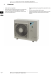
TABLE OF CONTENTS
1. PRECAUTION ÅÅÅÅÅÅÅÅÅÅÅÅÅÅÅÅÅÅÅÅÅÅÅÅÅÅÅÅÅÅÅÅÅÅÅÅÅÅÅÅÅÅÅÅÅÅÅÅÅÅÅÅÅÅÅÅÅÅÅÅÅÅÅÅÅ2
2. GENERAL SPECIFICATIONS ÅÅÅÅÅÅÅÅÅÅÅÅÅÅÅÅÅÅÅÅÅÅÅÅÅÅÅÅÅÅÅÅÅÅÅÅÅÅÅÅÅÅÅÅÅÅÅÅÅÅÅÅÅ3
3. NAMES OF MAJOR COMPONENTS
ÅÅÅÅÅÅÅÅÅÅÅÅÅÅÅÅÅÅÅÅÅÅÅÅÅÅÅÅÅÅÅÅÅÅÅÅÅÅÅÅÅÅÅÅÅÅÅ4
4. FUNCTION OF MAIN COMPONENTS
ÅÅÅÅÅÅÅÅÅÅÅÅÅÅÅÅÅÅÅÅÅÅÅÅÅÅÅÅÅÅÅÅÅÅÅÅÅÅÅÅÅÅÅÅÅÅ5
5. GENERAL INFORMATIONS ÅÅÅÅÅÅÅÅÅÅÅÅÅÅÅÅÅÅÅÅÅÅÅÅÅÅÅÅÅÅÅÅÅÅÅÅÅÅÅÅÅÅÅÅÅÅÅÅÅÅÅÅÅÅ6
6. CARE AND MAINTENANCE ÅÅÅÅÅÅÅÅÅÅÅÅÅÅÅÅÅÅÅÅÅÅÅÅÅÅÅÅÅÅÅÅÅÅÅÅÅÅÅÅÅÅÅÅÅÅÅÅÅÅÅÅÅÅ7
7. TROUBLE SHOOTING GUIDE
8. HOW TO DISASSEMBLE
9. WIRING DIAGRAM
ÅÅÅÅÅÅÅÅÅÅÅÅÅÅÅÅÅÅÅÅÅÅÅÅÅÅÅÅÅÅÅÅÅÅÅÅÅÅÅÅÅÅÅÅÅÅÅÅÅÅÅÅ8
ÅÅÅÅÅÅÅÅÅÅÅÅÅÅÅÅÅÅÅÅÅÅÅÅÅÅÅÅÅÅÅÅÅÅÅÅÅÅÅÅÅÅÅÅÅÅÅÅÅÅÅÅÅÅÅ10
ÅÅÅÅÅÅÅÅÅÅÅÅÅÅÅÅÅÅÅÅÅÅÅÅÅÅÅÅÅÅÅÅÅÅÅÅÅÅÅÅÅÅÅÅÅÅÅÅÅÅÅÅÅÅÅÅÅÅÅÅ11
10. REFRIGERANT CYCLE
ÅÅÅÅÅÅÅÅÅÅÅÅÅÅÅÅÅÅÅÅÅÅÅÅÅÅÅÅÅÅÅÅÅÅÅÅÅÅÅÅÅÅÅÅÅÅÅÅÅÅÅÅÅÅÅ12
11. EXPLODED DIAGRAM AND PARTS LIST
ÅÅÅÅÅÅÅÅÅÅÅÅÅÅÅÅÅÅÅÅÅÅÅÅÅÅÅÅÅÅÅÅÅÅÅÅÅÅÅÅÅ13
1
1. PRECAUTION
Please observe the following instructions.
1. Turn off unit.
Make sure the unit is OFF and the AC cord is unplugged before repairing or servicing.
2. In case of checking the circuit unavoidably while the unit is connected with power source, be careful
not to connect with the part of electric charge.
You may cause electric shock.
3. Use of proper part if you need to replace the part, be sure to use genuine part of servicing model.
Do not repair or replace the electric contact part.
Consumer must not repair the unit, because it is dangerous.
4. Use of proper tool.
You must use the proper tool to repair the unit, and use the measuring appliance adjusted accurately.
5. Damage of electric wire and power cord when servicing.
Check electric wire and a surely replace a damage electric wire and a damage power cord.
6. Never use connecting the middle of wire, after cutting the middle of wire.
It may cause a fire and trouble.
7. Checking the insulation resistance.
After you complete the assembly of unit, surely check the insulation resistance.
Confirm that the insulation resistance of the power line and the ground terminal is over 30MΩ by measuring insulation
resistance.
8. Checking the ground.
After checking the ground, servicing it completely.
9. Checking the installation.
After checking the installation, servicing it completely.
10. Care children.
When servicing, do not make the children approach the air-conditioner.
2
2. GENERAL SPECIFICATIONS
MODEL
DWC-070C
ITEM
Function
DWC-091C
Cooling only
Power source
AC 115V, 60Hz, Single phase
Btu/h
7,390 Btu/h
9,000 Btu/h
Kcal/h
1,862 Kcal/h
2,268 Kcal/h
Btu/wh
10.0 Btu/wh
9,6 Btu/wh
Kcal/wh
2.52 Kcal/wh
2.42 Kcal/wh
Pts/h
2.36 Pts/h
3.04 Pts/h
Power Input
739 W
938 W
Running Current
7.2A
9.6A
Cooling Capacity
Energy Efficiency Ratio
Dehumidification
Electrical Data
Type
Compressor
Rotary
Model
QB110CL12A
QK141CN12A
Capacitor
35µF-370VAC
40µF-370VAC
Model
A9525HS601-1
A9525HS602
Capacitor
4µF-370VAC
7µF-370VAC
Motor
Indoor-Fan
Blower-Fan
Outdoor-Fan
Propeller-Fan
Unit(W x H x D)
18.5(W) x 13.8(H) x 18.9(D) Inch (470(W )x 350(H) x 480(D) mm)
PACKING(W x H x D)
21.3(W) x 17.3(H) x 21.7(D) inch (540(W )x 440(H) x 550(D) mm)
Net Weight
63 lbs (28.5Kg)
65 lbs (29.5Kg)
Gross Weight
66 lbs (30.0 Kg)
68 lbs (31.0Kg)
Dimensions
Weight
3
3.NAMES OF MAJOR COMPONENTS
1
1
2
2
¤
3
3
¤æ
8
5
9
8
5
9
4
7
6
4
7
6
¤
NO
PART NAME
NO
PART NAME
1
CABINET
7
AIR INTAKE
2
BLADE VERTICAL
8
AIR FILTER
3
COOL AIR DISCHARGE
9
CONTROL PANEL
4
GRILL FRONT
10
PLATE WINDOW TOP
5
KNOB SELECTOR
11
FRAME WINDOW KIT
6
KNOB THERMOSTAT
12
SHUTTER WINDOW
4
4. FUNCTION OF MAIN COMPONENTS
1. ROTARY SWITCH (SELECTOR)
Please refer to the part of selector in the chapter 9 (Wiring Diagram).
The rotary switch (selector) controls the fan motor’s rotation speed, and has five positions.
The function of the five position is as follow.
SELECTOR
¡
OFF: This position stops all operations of the air conditioner.
¡
HIGH COOL: This position provides the maximum air flow for rapid
cooling, dehumidifying and dust removing operations.
(Use this position on sultry summer days.)
¡
LOW COOL: This position provides the minimum air flow for quiet
cooling, dehumidifying operations.
(Use this position on suitable for night-time.)
¡
HIGH FAN: This position provides the maximum air fiow alone fan
operation without cooling operation.
LOW FAN: This position provides the minimum air flow air flow alone
fan operation without cooling operation.
OFF
LOW
FAN
LOW
COOL
HIGH
FAN
HIGH
COOL
¡
2. THERMOSTAT (TEMPERATURE CONTROL)
THERMOSTAT
¡
The Thermostat automatically starts and stops operation in order to keep
the room temperature at a proper level, and this results in efficient use of
power and economical cooling.
¡
Turn clockwise for a cooler room temperature.
¡
Turn counter-clockwise for a warmer room temperature.
COOLER
3. MOTOR
The motor is used to rotate the indoor and outdoor fan so that the room air can be recirculated.
4. FAN
¡
¡
BLOEWR FAN: The Blower draws hot air from the room through the Evaporator and then discharges it back into the
cool air. It circulates the room air.
PROPELLER FAN: The propeller draws outdoor air through louvering and cools Condenser, and then blows the hot
air out.
5. CAPACITOR
The Capacitor enlarges the difference of phase between main coil and sub coil so that the Compressor and Fan Motor
starts well.
6. ACCUMULATOR
The Accumulator blocks the unflow of liquid refrigerant and impurities into the Compressor.
5
5. GENERAL INFORMATIONS
1. CHANGING AIR FLOW DIRECTION
Air flow deflectors divert air from center flow to left or right.
Adjust deflectors for desired air flow pattern.
2. AIR FLOW AROUND UNIT
Check in door grill and outdoor louvers for air flow obstructions. Do not block air flow to and from unit. The outdoor coil
should be checked and periodically cleaned for debris that may collect and block unit air flow. If air flow is obstructed
or deflected back into unit, the compressor may cycle on and off rapidly, causing early compressor failure.
3. Electrical Grounding Instructions.
This appliance is equipped with a three-prong(grounding) plug for protection against possible shock hazards. If a twoprong wall receptacle is encountered, the customer is required to contact a qualified electrician and have the twoprong wall receptacle replaced with a properly grounded three-prong wall receptacle in accordance with the National
Electrical Code.
4. USE OF EXTENSION CORDS
Because of potential safety hazards under certain conditions we strongly recommend against the use of an extension
cord. However, if you still elect to use an extension cord, it is absolutely necessary that it be a UL listed 3-wire
grounding type appliance extension cord rated has a 3-blade grounding plug and a 3-slot receptacle that will plug into
appliance. The marked rating of the extension cord should be 115V 15A or more.
5. DRAIN HOLE AND WATER DRIPPING OUTSIDE
Locate drain hole at the rear of unit. Water in base pan is picked up by the fan blade and thrown onto the warm
outdoor coil where it evaporates. The air conditioner must be installed level or tited or slightly to the outside for proper
water disposal. On exceptionally hot and humid days the air conditioner may permit excess water to pass thru rear
drain hole or overflow. This should be considered normal.
6
6. CARE AND MAINTENANCE
1. AIR FILTER
Clean the air filter, which removes dust inside the room.
It should be washed at least once every week during operation.
1. Remove the Air Filter from the front grill by pulling up.
2. Clean Air Filter with a vacuum cleaner or lukewarm, soapy water.
3. Shake it when clean to remove moisture completely. Replace it.
2. CLEANING THE AIR CONDITIONER
1. At least once a year, remove cabinet and thoroughly clean air conditioner. Have the unit inspected by an authorized
servicer to ensure unit is functioning properly.
2. Wash air conditioner with lukewarm, soapy water as needed. Rinse and dry thoroughly.
3. If using concentrated liquid detergent, dilute in warm water first.
4. Front grill may be wiped off with a cloth dampened in a mild detergent solution.
5. Cabinet may be washed with mild soap or detergent and lukewarm water, then polished with liquid wax for
appliances.
6. Condenser and Evaporator coils should be cleaned at the beginning of each cooling season. Use a soft brush or
vacuum cleaner to clean them, making sure that the Condenser and Evaporator coils are not damaged.
7. Do not use abrasive cleaners. These items scratch, crack and discolor surfaces.
7
7. TROUBLE SHOOTING GUIDE
TROUBLE
Fan motor and
compressor do not
run
SITUATION
1. Power failure
ANALYSIS
CAUSE
REMEDY
1) Power plug
1) Power failure
¡
Consult your electric company
2) Circuit breaker
2) Circuit breaker is tripped
¡
In case of a breaker, turn it on
and off a few times
¡
Replace the power plug
¡
Repair or replace the
receptacle
¡
Replace the cord or lead wire
¡
Replace the compressor or
connection wire
¡
Replace
¡
Repair or replace
¡
Turn knob for cooler setting
¡
Repair or replace the swtting
¡
Repair
¡
Repair or replace
¡
Replace
¡
Repair
¡
Consult your electric company
¡
Check the capacity of wire
¡
Ventilate well and remove the
heat source
3) Power plug is not contacting
2. Power is supplied,
but the equipment
does not run
1) receptacle
¡
Disconnection
2) Operation switch
¡
Mechanical failure of switch
3) Cord or lead wire to
the switch
1) Disconnection
2) Malfunction of contact
Switch is in “cool”
position but the
compressor does not
run
1. Not operating at all
Disconnection or burned-out
1) Compressor
¡
2) Thermostat
1) Failure
2) Malfunction
3) Knob is not set to the proper
setting
3) Selector switch
¡
Failure of malfunction of proper
setting
1) Disconnection
4) O.L.P
2) Malfunction of contact
Lack of capacity
¡ Disconnection
5) Capacitor
2. Compressor
¡
1) The voltage exceeded allowed
range (110V-120V)
1) Electricity
2) Capacity of wire is not
sufficient
2) Room temperature
and outside
temperature
¡
Extremely high
¡
Burned-out
¡
Replace
3) Compressor
¡
Malfunction
¡
Replace
4) O.L.P
¡
Lack of capacity
¡
Replace
1) Thermostat
¡
Malfunction
¡
Replace
2) Capacitor
¡
Lack of capacity
¡
Replace
3) O.L.P
¡
Malfunction
¡
Replace
5) Capacitor
3. Frequent start and
stop
8
TROUBLE
SITUATION
The compressor runs
but the motor doesn’t
run
Both fan motor and
compressor are
running but cooling is
bad
ANALYSIS
CAUSE
¡
Blocked by others
¡
Repair
¡
Disconnection or burned-out
electric cord
¡
Replace the fan motor
¡
Failure malfunction of contact
¡
Replace
¡
Disconnection of malfunction of
contact
¡
Check the circuit
1) Refrigerant system is choked
¡
Repair
2) Compressor failure
¡
Repair
3) Leakage of refrigerant gas
¡
Recharge refrigerant gas
1) Refrigerant system
1) Refrigerant system is choked
¡
Check and repair refrigerant
system
2) Filter
2) Compressor failure
¡
Replace
3) Heat exchanger of
condenser
3) Leakage of refrigerant gas
¡
Check a part of Leakage and
repair
¡
Repair and recharge
¡
Clean the air fiter
¡
Clean the unit
1) Fan
2) Fan motor
3) Capacitor
4) Fan motor circuit
Not cooling at all
Insufficient cooling
REMEDY
Refrigerant system
4) Refrigerant charge is too high
¡
Clogged up with dust
1) Fin is cogged up with dust
2) The ventilation is not good
Shade the unit from the
sunlight
¡ Remove the added heat
source
¡
3) The unit is exposed to the
sunlight
4) Other heat source is added in
the room
Vibration & Noise
¡
Install the unit perfectly
1) Fan is contacted with
obstacles
¡
Remove obstacles
2) Fixing bolt
¡
Tighten the bolt
1) Installation place
¡
2) Fan
Installation of the unit is
imperfectly done
3) Fixing screws
4) Electric
components
¡
Have a screw loose
¡
Tighten the screw
¡
Electrical noise
¡
Exchange the components
The front is lower than rear
side
¡
Make rear side of the unit
lower than the front
Water leakage into
room
¡
Installation condition
¡
Electric shock
(Leakage of current)
¡
Insulation of
components
1)Insulation defect of wiring and
lead wire
¡
Check the unit’s Leakage of
current.
2) Leakgae of current due to the
dew or rust
¡
Replace the defective parts or
components
9
8. HOW TO DISASSEMBLE
Please refer to the chapter 11 (Exploded diagram and parts list).
1
2
Before service of
1. Stop the unit, remove the power cord from the receptacles.
any part.
2. Move the unit to the safe location for the suitable work.
Ass’y Fan Motor
1. Remove Front Grill
- Fan Motor
- Remove Filter Pre.
- Propeller Fan
- Remove screw(1 point) in Front Grill.
- Blower Fan
2. Remove Cabinet from the unit.
- Remove screws (8 point) from the unit’s sides.
3. Remove Scroll upper.
4. Remove Plate Scroll
- Remove screws (3 point) from Plate Scroll’s sides.
5. Remove Ass’y Control Box
- Remove screws (3 point).
- Remove wires in the each components.
6. Remove wires in the Panel Housing.
7. Remove screws (7 point) from Ass’y Fan Motor’s sides.
- Ass’y Fan Motor is assembly of Fan Motor, Propeller and Blower Fan, Orifice
and Panel Housing.
8. Lift the Ass’y Fan Motor from the unit.
9. Remove hex-nut (2 point) from the shaft of Fan Motor.
10. Remove Propeller Fan from the shaft of Fan Motor.
11. Remove Blower Fan from the shaft of Fan Motor.
12. Remove Fan Motor from Panel Housing.
- Remove screws (4 point).
3
Ass’y Control Box
1. Same as the procedure 1 to 5 in the Item 2.
- Rotary Switch (selector)
- Thermostat
- Capacitor
- Power Cord
4
O.L.P
1. Same as the procedure 1 to 2 in the Item 2.
2. Remove Terminal Cover from Compressor.
- Remove hex-nut (1 point).
10
9. WIRING DIAGRAM
BK
WH
AC115V/60Hz
SELECTOR SWITCH
1
2
7
HiFAN
GN
LO- OFF LO- HiFAN
COOL COOL
BL
(Lo)
4
YW
(Hi)
8
BR
F.M
CAPACITOR
O.L.P
BR
F
OR
C
COMP
GY
THERMOSTAT
R
S
OR
RD
11
C
H
10. REFRIGERANT CYCLE
Evaporator
Blower fan
M
MOTOR
Accumulator
Compressor
Propeller fan
Condenser
12
Capillary tube
11. EXPLODED DIAGRAM AND PARTS LIST.
§öDWC-070C PARTS LIST
NO.
1
2
3
4
5
6
7
8
9
10
11
12
13
14
15
16
17
18
19
20
21
22
23
24
25
26
27
28
29
30
31
32
33
34
35
36
37
38
39
40
41
42
43
44
45
46
47
48
49
50
51
52
53
54
55
56
57
58
60
61
62
63
64
65
66
67
68
69
70
71
72
73
74
75
COMPONENTS
PAN BASE
BOLT-COMP
SCROLL LOWER
SEALING PUTTY
COMPRESSOR
GROMMET
WASHER PLAN
NUT LOCK
AS CONDENSOR
SCREW TAPPING
PIPE COND IN
AS PIPE CAPILLARY
PIPE CAPI
AS EVAPORATOR
AS PIPE EVA OUT
AS PIPE EVA IN
AS PIPE SUCTION
SCREW TAPPING
MOTOR FAN
PANEL HOUSING
COVER ORIFICE
SCREW TAPTITE
SCRE TAPPING
FAN BLOWER
WASHER PLAIN
NUT HEX(R)
FAN PROPELLER
WASHER PLAIN
NUT HEX(L)
BUSHING GUIDE
LOCK TWIST STANDOFF
BUSHING HOUSING
CONTROL BOX
ROTARY S/W
SCREW MACHINE
THERMOSTAT
CAPACITOR
CLAMP CAPACITOR
SCREW TAPTITE
POWER CORD
SCREW TAPTITE
SCREW TAPTITE
LABEL CIRCUIT
BUSHING COVER
HARNESS ROTARY S/W
SEAL CONT BOX
HARNESS COMP AS
OLP
GASKET
COVER TERMINAL
NUT
SEAL EVA TOP
PLATE SCROLL
SEAL SCROLL
SCREW TAPPING
SCROLL UPPER
SEAL COND TOP
AS CABINET
PLT WINDOW TOP
SCREW TAPPING
SEAL CAB TOP
SEAL CAB SIDE(R)
SEAL CAB SIDE(L)
SEAL CAB FLANGE
SCREW TAPPING
GRILLE FRONT
SEAL FRONT (C)
SEAL FRONT (A)
SEAL FRONT (B)
BLADE
DECO FRONT
SCREW TAPPING
AS KNOB
FILTER PRE
CODE
3100300700
3106002400
3106600400
2221040001
3100039100
3108100000
7400208411
7392801211
3100029400
7112401211
3104414400
3100034300
3104414600
3100029300
3100034500
3100034400
3100034600
7112401211
3108002710
3104201500
3101402400
7S432X4081
7122401211
3101801820
3106000600
3106000500
3101801910
3106000600
3106000400
3100700600
3103800400
3100700900
3100504000
5S10503100
7001400611
5SM0101600
3109501600
3101201600
7S432X4081
3101397900
7S432X4081
7S432X4081
3103520500
3100701100
3102702100
3108502900
3102702000
—
—
—
—
3108502700
3104504800
3108503800
7122401211
3106600300
3108502800
3100034900
3104505600
7112401211
3108503100
3108503400
3108503200
3108503000
7112401211
3102401900
3108503700
3108503500
3108503600
3106501100
3101600400
7112400811
3100035200
3101901800
SPECIFICATION
P.P T30% or P.P CaCl3(40%)
M8XP1.25
E.P.S
JOINT SEALER
QB110CL12A
EPDM 45
IB 8.4ƒTOD22ƒTT1.6
M8P1.25(R)
2RƒTICƒT17S
T1 TRS 4X12
OD7.94ƒTT0.7
DWC-070C
ID1.4
2RƒT2CƒT12S
C122OT-OD0.7
C122OT-OD0.7
OD9.52
T1 TRS 4X12
A9525HS601-1
SGCC(Z-27) T1.0
PP
TT3 TRS SE 4X8
T2S TRS 4X12
ABS+GF20%
M6X19.8
M6(R)
ABS
M6X19.8
M6(L)
NBR
DASTL-3NA
NBR
SGCC T0.8
SRB315-4-7D (DAESUNG)
M/C PAN 4X6
PFA 602D-06B
4+35uF/370VAC
SGCC T0.8
TT3 TRS SE 4X8
SJT AWG #16X3
TT3 TRS SE 4X8
TT3 TRS SE 4X8
P.E T0.05
DACB-008
AWG-16 UL (BR)
F-PE T0.5
AWG-16 UL (BR/RD/OR)
MRA 12061-12026
SILICON
P.C
HEXAGON FLANGE
F-US L350X40XT5
PP+T30%
F-US L115X60XT5
T2S TRS 4X12
EPS
F-US L400X30XT10
SGCC T0.8
SECC T1.2
T2S TRS 4X12
F-US L470X155X10
F-US L310X155XT5
F-US L310X90XT5
F-US L540X10XT5
T2S TRS 4X12
ABS
F-US L80X20XT30
F-US L600X20XT10
F-US L420X20XT10
PP
PC T0.4
T1 TRS 4X8 MFZN
ABS
ABS (MESH #32)
13
Q’TY
1
3
1
0.05
1
3
3
3
1
2
1
1
1
1
1
1
1
2
1
1
1
4
3
1
1
1
1
1
1
1
3
1
1
1
4
1
1
1
1
1
1
1
1
0.4
1
1
1
1
1
1
1
1
1
1
3
1
1
1
1
3
1
1
1
1
6
1
2
1
1
2
1
1
2
1
REMARK
Kg
PAINT
PAINT
§öDWC-070C EXPLODED DIAGRAM
14
4
§öDWC-091C PARTS LIST
NO.
1
2
3
4
5
6
7
8
9
10
11
12
13
14
15
16
17
18
19
20
21
22
23
24
25
26
27
28
29
30
31
32
33
34
35
36
37
38
39
40
41
42
43
44
45
46
47
48
49
50
51
52
53
54
55
56
57
58
60
61
62
63
64
65
66
67
68
69
70
71
72
73
74
75
COMPONENTS
PAN BASE
BOLT-COMP
SCROLL LOWER
SEALING PUTTY
COMPRESSOR
GROMMET
WASHER PLAN
NUT HEX(R)
AS CONDENSOR
SCREW TAPPING
AS PIPE COND IN
AS PIPE CAPILLARY
PIPE CAPI
AS EVAPORATOR
AS PIPE EVA OUT
AS PIPE EVA IN
AS PIPE SUCTION
SCREW TAPPING
MOTOR FAN
PANEL HOUSING
COVER ORIFICE
SCREW TAPTITE
SCRE TAPPING
FAN BLOWER
WASHER PLAIN
NUT HEX(R)
FAN PROPELLER
WASHER PLAIN
NUT HEX(L)
BUSHING GUIDE
LOCK TWIST STAND OFF
BUSHING HOUSING
CONTROL BOX
ROTARY S/W
SCREW MACHINE
THERMOSTAT
CAPACITOR
CLAMP CAPACITOR
SCREW TAPTITE
POWER CORD
SCREW TAPTITE
SCREW TAPTITE
LABEL CIRCUIT
BUSHING COVER
HARNESS ROT S/W
SEAL CONT BOX
HARNESS COMP AS
OLP
GASKET
COVER TERMINAL
NUT
SEAL EVA TOP
PLATE SCROLL
SEAL SCROLL
SCREW TAPP
SCROLL UPPER
SEAL COND TOP
AS CABINET
PLT WINDOW TOP
SCREW TAPPING
SEAL CAB TOP
SEAL CAB SIDE(R)
SEAL CAB SIDE(L)
SEAL CAB FLANGE
SCREW TAPPING
GRILLE FRONT
SEAL FRONT (C)
SEAL FRONT (A)
SEAL FRONT (B)
BLADE
DECO FRONT
SCREW TAPPING
AS KNOB
FILTER PRE
CODE
3100300700
3106002400
3106600400
2221040001
3100049300
3108100000
3106000600
3106000500
3100049700
7112401211
3104414400
3100034300
3104401400
3100049600
3100050000
3100034400
3100050100
7112401211
3108003500
3104201500
3101402400
7S432X4081
7122401211
3101801820
3106000600
3106000500
3101801910
3106000600
3106000400
3100700600
3103800400
3100700900
3100504000
5S10503100
7001400611
5SM0101600
3109502200
3101201600
7S432X4081
3101397900
7S432X4081
7S432X4082
3103512000
3100701100
3102702100
3108502900
3102702000
SPECIFICATION
P.P T30% or P.P CaCl3(40%)
M8XP1.25
EPS
JOINT SEALER
QK141CN12A
NBR
T1.0
M6(R)
3RƒT2CƒT17S
T1 TRS 4X12
C122OT-OL
DWC-091C
ID1.0
3RƒT2CƒT12S
C122OT-OD0.7
C122OT-OD0.7
OD9.52
T1 TRS 4X12
A9525HS602
SGCC T1.0 (Z-27)
PP
TT3 TRS SE 4X8
T2S TRS 4X12
ABS
M6X19.8
M6(R)
ABS+GF20%
M6X19.8
M6(L)
NBR
DASTL-3NA
NBR
SGCC T0.8
SRB315-4-7D
M/C PAN 4X6
PFA 602D-06B
7+40uF/370VAC
SGCC T0.8
TT3 TRS SE 4X8
SJT AWG #16X3
TT3 TRS SE 4X8
TT3 TRS SE 4X8
P.E T0.05
DACB-008
AWG-16 UL (BR)
F-PE T0.5
AWG-16 UL (BR/RD/OR)
MRA 12022-12004
SILICON
P.C
HEXAGON FLANGE
F-US L350X40XT5
PP+T30%
F-US L115X60XT5
T2S TRS 4X12
EPS
F-US L400X30XT10
SGCC T0.8
SECC T1.2
T2S TRS 4X12
F-US L470X155X10
F-US L310X155XT5
F-US L310X90XT5
F-US L540X10XT5
T2S TRS 4X12
ABS
F-US L80X20XT30
F-US L600X20XT10
F-US L420X20XT10
PP
PC T0.4
T1 TRS 4X8 MFZN
ABS
ABS (MESH #32)
3108502700
3104504800
3108503800
7122401211
3106600300
3108502800
3100034900
3104505600
7112401211
3108503100
3108503400
3108503200
3108503000
7112401211
3102401900
3108503700
3108503500
3108503600
3106501100
3101600400
7112400811
3100035200
3101901800
15
Q’TY
1
3
1
0.05
1
3
1
2
1
1
2
1
1
1
1
2
1
1
1
4
3
1
1
1
1
1
1
1
3
1
1
1
4
1
1
1
1
1
1
1
1
0.4
1
1
1
1
1
1
1
1
1
1
3
1
1
1
1
3
1
1
1
1
6
1
2
1
1
2
1
1
2
1
REMARK
Kg
PAINT
PAINT
§öDWC-091C EXPLODED DIAGRAM
1
6
DAEWOO ELECTRONICS CO., LTD.
686, AHYEON-DONG MAPO-GU SEOUL, KOREA
C.P.O. BOX 8003 SEOUL, KOREA
TELEX: DWELEC K28177-8
CABLE: “DAEWOOELEC”
FAX: 02) 590-6291
TEL: 02) 360-7114/590-6151~5
http://www.dwe. daewoo.co.kr
S/M NO.: DWC070C010
PRINTED DATE: NOV.1998
Service Manual
Window Type
Room Air Conditioner
Model: DWC-070C
DWC-091C
R
US
LISTED
ROOM AIR CONDITIONER
39WK
¡sfl
This instrument is listed by Underwriter¡
Laboratories, Inc. It is designed and manufactured to
meet rigid U.L. safety standards against X-radiation,
fire, casualty and electrical hazards.
DAEWOO ELECTRONICS CO., LTD.