1
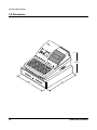
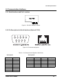
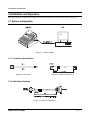
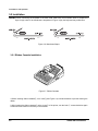
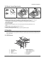
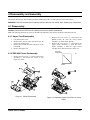
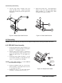
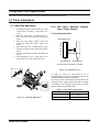
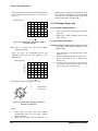
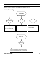
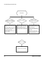
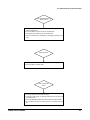
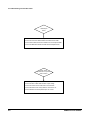
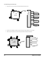
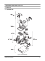
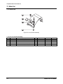
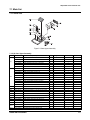
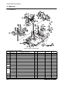
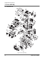
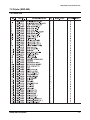
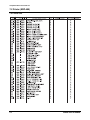
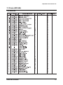
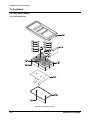
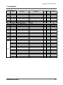
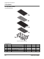
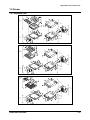
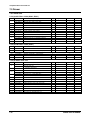
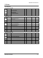
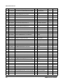
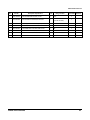
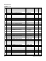
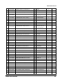
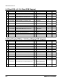
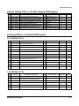
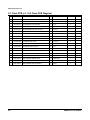
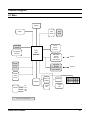
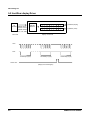
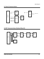
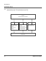
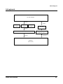
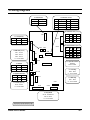
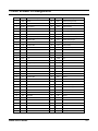
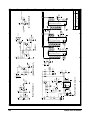
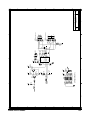
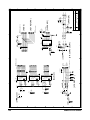
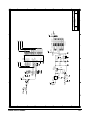
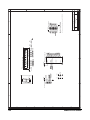
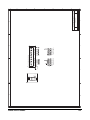
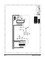
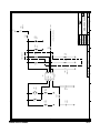
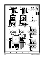
ELECTRONIC CASH REGISTER ER-5100 / ER-5140 ER-5115 / ER-5140FP SERVICE Manual ELECTRONIC CASH REGISTER CONTENTS 1. Precaution Statements 2. Product Specifications 3. Installation and Operation 4. Disassembly and Assembly 5. Alignment and Adjustment 6. Troubleshooting 7. Exploded Views and Parts List 8. PCB Parts List 9. Block Diagram 10. Wiring Diagram 11. ASIC SCR60K Pin Assignment 12. Schematic Diagrams About this Manual This service manual describes how to perform hardware service maintenance for the SAM4S ER-5100 Series Electronic Cash Register. Notes Notes may appear anywhere in the manual. They describe additional information about the item. Precaution symbols . Indicates a Safety Precaution that applies to this part component. . Indicates the part or component is an electro-statically sensitive device. Use caution when handling these parts. Acronym ASIC ECR EPROM ESD Ext. F GND IC N.C. PCB R.. RAM ROM SRAM T.. Definition Application for Specific Integrated Circuit Electronic Cash Register Electric Programmable ROM Electro-statically Sensitive Device Extension Fiscal Ground Integrated Circuit Not Connected Printed Access Memory Receive Random Access Memory Read Only Memory Static Random Access Memory Transmission Copyright ⓒ 2004 by Shin Heung Precision. All right reserved. This manual may not, in whole or in part, be copied, photocopied, reproduced, translated or converted to any electronic or machine readable from without prior written permission of Shin Heung Precision . SAM4S ER-5100 SERIES ER-5100 Service Manual March 2004. V1.0 Printed in KOREA Overview of this System ECR This service manual provides the technical information for many individual component systems, circuits and gives an analysis of the operations performed by the circuits. If you need more technical information, please contact our service branch or R&D center. Schematics and specifications provide the needed information for the accurate troubleshooting. All information in this manual is subject to change without prior notice. Therefore, you must check the correspondence of your manual with your machine. No part of this manual may be copied or reproduced in any form or by any means, without the prior written consent of Shin Heung Precision Note: Before using this System Electronic Cash Register (ECR) for the first time, leave it powered on in the REG mode for at least twenty-four hours. This allows the Ni-MH battery, which maintains the memory of the SECR while the power is off, to charge completely. 1 Precaution Statements Follow these safety, servicing and ESD precautions to prevent damage and to protect against potential hazards such as electrical shock. 1-1 Safety Precautions 1. Be sure that all of the built-in protective devices are replaced. Restore any missing protective shields. 2. When reinstalling the chassis and its assemblies, be sure to restore all protective devices, including nonmetallic control knobs and compartment covers. 3. Make sure there are no cabinet openings through which people-particularly children-might insert fingers and contact dangerous voltages. Such openings include excessively wide cabinet ventilation slots and improperly fitted covers and drawers. 4. Design Alteration Warning: Never alter or add to the mechanical or electrical design of the ECR. Unauthorized alterations might create a safety hazard. Also, any design changes or additions will void the manufacturer’s warranty. 5. Components, parts and wiring that appear to have overheated or that are otherwise damaged should be replaced with parts that meet the original specifications. Always determine the cause of damage or over- heating, and correct any potential hazards. SAM4S ER-5100 SERIES 6. Observe the original lead dress, especially near the following areas: sharp edges, and especially the AC and high voltage supplies. Always inspect for pinched, out-of-place, or frayed wiring. Do not change the spacing between components and the printed circuit board. Check the AC power cord for damage. Make sure that leads and components do not touch thermally hot parts. 7. Product Safety Notice: Some electrical and mechanical parts have special safety-related characteristics which might be obvious from visual inspection. These safety features and the protection they give might be lost if the replacement component differs from the original - even if the replacement is rated for higher voltage, wattage, etc. Components that are critical for safety are indicated in the circuit diagram by shading, ( ) or ( ). Use replacement components that have the same ratings, especially for flame resistance and dielectric strength specifications. A replacement part that does not have the same safety characteristics as the original might create shock, fire or other hazards. 1-1 1 Precaution Statements 1-2 Servicing Precautions WARNING: First read the-Safety Precautions-section of this manual. If some unforeseen circumstance creates a conflict between the servicing and safety precautions, always follow the safety precautions. WARNING: An electrolytic capacitor installed with the wrong polarity might explode. 1. Servicing precautions are printed on the cabinet. Follow them. 2. Always unplug the units AC power cord from the AC power source before attempting to: (a) Remove or reinstall any component or assembly (b) Disconnect an electrical plug or connector (c) Connect a test component in parallel with an electrolytic capacitor 3. Some components are raised above the printed circuit board for safety. An insulation tube or tape is sometimes used. The internal wiring is sometimes clamped to prevent contact with thermally hot components. Reinstall all such elements to their original position. 4. After servicing, always check that the screws, components and wiring have been correctly reinstalled. Make sure that the portion around the serviced part has not been damaged. 5. Check the insulation between the blades of the AC plug and accessible conductive parts (examples: metal panels and input terminals). 6. Insulation Checking Procedure: Disconnect the power cord from the AC source and turn the power switch ON. Connect an insulation resistance meter (500V) to the blades of AC plug. The insulation resistances between each blade of the AC plug and accessible conductive parts (see above) should be greater than 1 megohm. 7. Never defeat any of the B+ voltage interlocks. Do not apply AC power to the unit (or any of its assemblies) unless all solid-state heat sinks are correctly installed. 8. Always connect an instrument’s ground lead to the instrument chassis ground before connecting the positive lead ; always remove the instrument’s ground lead last. 1-3 Precautions for Electrostatically Sensitive Devices (ESDs) 1. Some semiconductor (solid state) devices are easily damaged by static electricity. Such components are called Electrostatically Sensitive Devices (ESDs); examples include integrated circuits and some fieldeffect transistors. The following techniques will reduce the occurrence of component damage caused by static electricity. 2. Immediately before handling any semiconductor components or assemblies, drain the electrostatic charge from your body by touching a known earth ground. Alternatively, wear a discharging wrist-strap device. (Be sure to remove it prior to applying power - this is an electric shock precaution.) 3. After removing an ESD-equipped assembly, place it on a conductive surface such as aluminum foil to prevent accumulation of electrostatic charge. 4. Do not use Freon-propelled chemicals. These can generate electrical charges that damage ESDs. 5. Use only a grounded-tip soldering iron when soldering or unsoldering ESDs. 6. Use only an anti-static solder removal device. Many solder removal devices are not rated as anti-static; these can accumulate sufficient electrical charge to damage ESDs. 1-2 7. Do not remove a replacement ESD from its protective package until you are ready to install it. Most replacement ESDs are packaged with leads that are electrically shorted together by conductive foam, aluminum foil or other conductive materials. 8. Immediately before removing the protective material from the leads of a replacement ESD, touch the protective material to the chassis or circuit assembly into which the device will be installed. 9. Minimize body motions when handling unpackaged replacement ESDs. Motions such as brushing clothes together or lifting a foot from a carpeted floor can generate enough static electricity to damage an ESD. SAM4S ER-5100 SERIES 2 Product Specifications Specifications are correct at the time of printing. Product specifications are subject to change without notice. See below for product specifications. 2-1 Specifications Item Description AC Power Source Power Consumption Remark AC 120V, 60Hz USA AC 230V, 50Hz Europe 35W max USA and Europe 1 pair, 9-pin Dot matrix R/J Printer Printing speed; 3.0 lines per second Receipt / Journal paper sensor Processor SCR60K Memory * Main PCB Default : SRAM(KM681000*1) : 128kbyte EPROM(27C010*1) : 128kbyte or EPROM(27C020*1) : 256kbyte Ext. : SRAM(KM681000*1) : 128kbyte * Fiscal(ER-5140FP) Default : EPROM(27C512*1) : 64kbyte Ext. : EPROM(27C010*1) 128kbyte Data Storage 60 Days Battery Ni-MH,3.6V,70mAh Charging time Display Keyboard When battery fully charged : 24 hours Front : 10-digit display (Front display) Rear : 10-digit display (Real display) 160-Key ER-5100 90-Key ER-5140/5140FP 60-Key Default Interface Ext. Drawer Packing Carton ER-5115 - RS-232C : 1 port (Optional Board I) or Modular Jack : 1 ports (Optional Board I) - RS-232C : 2 port (Optional Board II) 5C5B USA 8C4B Europe EURO 8C7B Weight : 9.3 Kg Dimensions : 400(W) x 450(L) x 111(H) Weight : 17.6 Kg Dimensions : 498(W) x 564(L) x 384(H) When packed millimeters millimeters Equipment specifications are subject to change without notice. SAM4S ER-5100 SERIES 2-1 2 Product Specifications 2-2 Dimensions 305 40 0 2-2 5 45 SAM4S ER-5100 SERIES 2 Product Specifications 2-3 Communication Interfaces 2-3-1 Serial Interfaces and Port Locations Figure 2-1. RS-232C Interface Locations 2-3-2 Pin Descriptions for Serial Interfaces (Optional P.C.B.) Figure 2-2. Pin Number Assignment Table 2-1. Pin Descriptions and Signals of Serial Ports Serial port #1 Serial port #2 Pin # Signal Pin # Signal Pin # Signal 1 N.C. 1 DTR 1 DTR 2 RxD 2 N.C. 2 N.C. 3 TxD 3 TxD 3 TxD 4 DTR 4 N.C. 4 N.C. 5 GND 5 RxD 5 Rxd 6 N.C. 6 GND 6 gnd 7 N.C. 8 DTR 9 N.C. SAM4S ER-5100 SERIES 2-3 2 Product Specifications Memo 2-4 SAM4S ER-5100 SERIES 3 Installation and Operation 3 Installation and Operation This chapter describes the method for installing the ECR system and shows the locations of the various feature items. 3-1 System configuration Figure 3-1. Terminal System 3-1-1 Terminator Specification Figure 3-2. Terminator Figure 3-4. Cable for Serial Port 2 3-1-2 Cable Specifications Figure 3-3. Cable for Serial Port 1 SAM4S ER-5100 SERIES 3-1 3 Installation and Operation 3-2 Installation WARING: When connecting the keyboard to the Main PCB, made sure the membrane sheet is shaped as in figure 3-6(a), below. If the membrane is shaped as in Figure 3-6(b), the keyboard may malfunction. Figure 3-6. Membrane Shape 3-2-1 Ribbon Cassette Installation Figure 3-7. Ribbon Cassette 1.Before inserting ribbon cassette②, turn. knob①(see Figure 4-4) counterclockwise to prevent twisting the ribbon. 2.After inserting the ribbon cassette② at the center③ of the printer, turn the knob ① counterclockwise again to make sure the ribbon moves freely in the cassette 3-2 SAM4S ER-5100 SERIES 3 Installation and Operation 3-2-2 Receipt / Journal Paper Insertion Figure3-8 Folding Paper for Insertion Figure3-9 Inserting the paper Figure3-10 Inserting the Journal Paper 1. Using a new roll of paper, unroll the paper about 150mm and fold the paper as shown in Fig 3-8 2. Insert fold paper into the chute ② of the printer. While holding the lever ① down, pull the paper out until the fold point ③ is completely out of the printer. And turn the knob ④ like an arrow. (Fig 3-9) 3. Cut the receipt paper. 4. Insert the journal into paper the silt ③ of the rewind spindle. Wind the spindle three or four times. 5. Push end disk ⑥ into the spindle as shown in Fig 3-10. 6. Insert the spool to the printer part ⑤. 7. When the journal paper is loose, rewind the spindle to tighten the paper. 3-3 Operation Note: Before using this Electronic Cash Register (ECR) for the first time, leave it powered ON in the REG mode for at least twenty-four hours. This allows the Ni-Cad battery, which maintains the ECRs memory while the power is OFF, to fully charge. 3-3-1 ECR Features 1 4 3 2 5 3 6 8 ① ② ③ ④ ⑤ Cover Printer Impact dot Printer Keyboard Drawer Drawer Lock Key SAM4S ER-5100 SERIES 7 ⑥ ⑦ ⑧ ⑨ Serial Interface Port Serial 1 (D-sub 9 Pin) *2 Serial 2 (Modular Jack) *1 Mode Key Switch Rear Display Clerk Key 3-3 3 Installation and Operation 3-3-2 Mode switch This position of the Key in the Mode Switch determines the action of the SECR. Table 3-1 shows the various modes that are available. Table 3-1. ECR Modes Mode Function VOID Cancel operation OFF Operation Stop REG Sales operation X X-level report generation Z Z-level report generation P Program mode MC Manager control Figure 3-14. Mode Switch 3-3-3 Keyboard Matrix 3 The ER-5100, ER-5140, ER-5115 and ER-1551F ECRs offer three different types of keyboards; 160-key, 90-key or 60-key as shown in Table 3-2. Table 3-2. Keyboard Types SAM4S ER-5100 SERIES Model Keys Type ER-5100 160 Membrane (Flat) ER-5140 90 Membrane ER-5115 60 Membrane Er-5115F/FP 60 Membrane 3-4 4 Disassembly and Assembly This chapter describes the Disassembling and Reassembling procedures for ER-5100, electronic cash registers. WARNING: This ECR contains electro-statically sensitive devices. Use caution when handling any components. 4-1 Disassembly Caution: Disconnect the ECR from the external power source before Disassembly. Note: The following directions are given for the ER-5100. differences between the models are identified in the text. 4-1-1 Upper Case Disassembly 1. 2. 3. 4. Lift off the Printer cover. Remove three screws ((B-6) and (B-11))on the Upper Case and loft it up. Remove the red and the white connectors on the main PCB. Remove the Upper Case. 4-1-2 ERP-400 Printer Disassembly 1. 2. 3. Remove the two screws, ⓑ, and remove the Ribbon Frame, B, from the Lower Frame assembly I, as shown in the drawing. Remove the four screws, ⓒ, and separate the Upper Frame Assembly, C, from the Lower Frame assembly, I. Pull the Upper Frame assembly in the direction shown in figure 4-2. PULLING DIRECTION UP Remove the four screws ⓐ on the Upper Frame Assembly, C, and remove the Cover, A. See Figure 4-1, below. FRONT Figure 4-1. Printer Disassembly SAM4S ER-5100 SERIES Figure 4-2. Separating Upper Frame from the Lower Frame. 4-1 4 Disassembly and Assembly 4. Turn the upper Frame Assembly, down and remove the three screws, . Remove the Stamp Paper Guide Assembly D, from the Upper Frame Assembly C. 5. Remove the left-side screw, , on the Platen Paper Guide, E. This screw connects the Platen Paper Guide Assembly E, -to Stamp Paper Guide Assembly, D. See figure 4-4, below. e E D Figure 4-3. Stamp Paper Guide Removal Figure 4-4. Platen Guide Removal 4-2 Assembly Caution: Adjust the Head Gap )see Alignment and Adjusts chapter) before returning the ECR to the owner. 4-2-1 ERP-400 Printer Assembly 1. 2. 3. Position the Platen Paper Guide Assembly, E, on the Stamp Paper guide Assembly, D, and replace the screw -ⓔ (see Figure 4-4, above). With the Upper Frame Assembly C, upside-down, position the Stamp Paper Guide Assembly, D, and replace the three screws –ⓓ (see Figure 4-3, above). Position the Upper Frame Assembly, C, on the Lower Frame Assembly, I, and replace the four screws ⓒ (see Figure 4-5, to the fight). Caution: Locate Stamp Pusher ⓕ on the hatched area as shown in the figure. 4. 5. 4-2 Position the Ribbon Frame, B, on the Lower Frame Assembly, I, and replace the two screws ⓑ (see Figure 4-1, above) Position the cover, A, on the Upper Frame Assembly, C, and replace the four screws_-ⓐ. C F Hatched area D Figure 4-5. Stamp Pusher Position SAM4S ER-5100 SERIES 4 Disassembly and Assembly 4-2-2 Upper Case Assembly 1. 2. 3. Position the Upper Case so that the connectors are within reach of the Main PCB. Replace the red and the white connectors. Position the Upper Case on the Lower Case and replace the three screws ((B-6) and (B-11)) Replace the Printer Cover. SAM4S ER-5100 SERIES 4-3 4 Disassembly and Assembly Memo 4-4 SAM4S ER-5100 SERIES 5 Alignment and Adjustments This chapter describes the methods for aligning and adjusting components in this ECR. 5-1 Printer Adjustments 5-1-1 Head Gap Adjustment 1. 2. 3. 4. 5. 6. Assemble the Upper Frame Assembly, A, to the Lower Frame Assembly, I and loosely fox screws . Wind the Head Gear counterclockwise to; move the Head to the right end of the Platen Guide. Insert the Gap Gauge (width 0.5mm) and tighten the Head and Platen. Tighten the screws . Wind the Head Gear counterclockwise again and move the Head to the left end of the Platen Guide. Insert the Gap Gauge (0.5mm) and tighten the screws. After tightening al screws , apply Nej-Lock (a brand of grease) on each of the four screws . 5-1-2 Roll Paper Near-End Detector (Type 1 Paper Sensor) 5-1-2-(a) Adjustment Point ADJUSTMENT SCALE #5 #4 #3 #2 #1 ADJUSTMENT POINT BRACKET P/END SLIDE BRACKET (SET FOR PAPER THICKNESS = 0.075MM) Figure 5-2. Adjustment Point As Figure 5-2 shows, the slide bracket is set at Adjustment Scale #3. This is the appropriate scale for the recommended paper thickness (0.075mm). The accuracy of the Near-End Detector depends on the Adjustment Scale setting and the Roll Paper Winding Core diameter. The only paper approved for use in this ECR has the following characteristics: Table 5-1. Roll Paper characteristics Characteristic Paper Thickness Figure 5-1. Head Gap Adjustment SAM4S ER-5100 SERIES Paper Width Measurement 0 075mm 44.5mm ± 0.5mm 5-1 5 Alignment and Adjustments The relationship between the Adjustment Scale and the paper remnant remaining on the core is as shown in figure 5-3. Winding Core may pull out of its holder due to the paper sticking to Winding Core, If the Winding Core pulls out of its holder, the Paper Sensor may indicate an inaccurate remnant length. Remnant of (m): 5-1-3 Clearing a Paper Jam 5 4 3 2 1 5-1-3-(a) Paper Jamming Causes 1. #1 #2 #3 #4 #5 Figure 5-3. Relationship: Adjustment Scale to Remnant Length Note: figure 5-3 applies only when using SAM4S recommended papers. Figure 5-4 shows the relationship between the Adjustment Scale and the outer diameter of the Winding Core. Adjusting Scale: 2. 5-1-3-(b) Clearing Procedure Caution: Always disconnect the power cord from the power outlet before working on the Paper Cutter. 1. 2. 3. 4. #5 #4 #3 #2 #1 When more than two papers have entered the paper path. When paper cutting remnants remain in the paper exit space. Open the Printer cover and remove the AutoCutter Cover 2. Remove all jammed paper at the Auto-Cutter. Replace Auto-Cutter Cover 2 and close the Printer cover. The Auto-Cutter will operate as soon as power is restored to the ECR. After cutting once, the Auto-Cutter goes to its normal state. 10 15 20 25 30 Outer diameter of paper winding core (Φ :mm ) D: d: Outer Diameter Inner Diameter Figure 5-4. relationship: Adjustment Scale to Winding core diameter Note: 1. 2. 5-2 When using roll paper other than SAM4S recommended paper, the roll paper remnant lengths will differ. When using roll paper with a red end mark, the SAM4S ER-5100 SERIES 6 Reference Information This chapter describes the methods for determining the source of malfunctions in this ECR. 6-1 Troubleshooting Key Board Problem Key Input Failure 1. Check the fuse on the Main PCB. 2. Check all Voltage states. 3. Check/Change the related circuit (IC9 ~IC11) on the Main PCB. Specific Key Buzzer Failure Malfunction 1. Check the affected keys and the data bus. 2. Check the diodes (D16~D35) 1. Check the related circuit with the buzzer(Q4,Q17,IC2,R10,R12,R23,R 24,R100,CC3,Buzzer) 4. Check whether the Printer (ERP400) is out of order. Drawer Failure Drawer does not Automatically open 1. Check the drawer Solenoid and the connector (both the ECR side and the Drawer side. 2. Check the manual open and closed states using the Drawer Key. 3. Check the IC4,TA3,TA4 and the related circuit on the Main PCB. SAM4S ER-5100 SERIES 6-1 6 Troubleshooting and Test Procedure Printer failure Motor, Stamp, Auto-cutter Printer head failure Or Paper feed Failure 1. Check whether the Printer is out of order. 2. Check whether the harness (CN7~CN9) are disconnected. 3. Check TA1 to TA4 and related circuits on the Main PCB. 1. Check the Head Pin and the Coil. 2. Check whether the harnesses (CN7~CN9) are disconnected. 3. Check or change the TA1~TA4 and the related circuits on the Main PCB. 4. Check whether the paper jam of the ribbon is twisted. Receipt/Journal Paper Sensing Failure 1. Check whether the dummy of the Paper Near End Sensor (Optional Item) is not working. 2. Check the Spring of the Sensor. 3. Check the switch operation status of the Sensor. 4. Check the wire soldering state. 5. Check the connection between the Main PCB and the Printer. Real Time Clock Failure Check the IC8, CC35, CC36 and X2 6-2 SAM4S ER-5100 SERIES 6 Troubleshooting and Test Procedure Front/Rear(Window/Turret) Display Failure. 1. Check/change the solder points and the connection harness of the Window Display PCB. 2. Check the CN6 connection harness on the Main PCB. 3. Check/change the related circuits on the Main PCB. 4. Check the HV5812P and the Digitron on the Display PCB and Turret PCB. Mode Key failure 1. Check the key-locked status and the connector insertion in the lock. 2. Check the RA3 on the Main PCB. Serial 1,2(Optional) Failure 1. Check the Cable connection with the CN18. 2. Check the solder points on Optional PCB (IC14,Q15 and Q16) and the related circuits. 3. Check the Bead Wire between the Main PCB and the Optional PCB. 4. Do Loop Back Test with the male D-sub 9Pin connected pin #2 and #3. SAM4S ER-5100 SERIES 6-3 6 Troubleshooting and Test Procedure Modular jack failure. 1. Check whether the Cable is short, open or etc. 2. Check the connection status between the CN19 and the cable. 3. Check the IC4,Q15,Q16 and the related circuit on the Optional PCB. 4. Check the Bead wire between the Main PCB and Optional PCB. System failure: System does not operate When all clear 1. Confirm input voltage is 120V/230V 2. Check the fuse on Main PCB and each output voltage. 3. Check the contact of the mode switch connector state.. 4. Check whether the FPC of Key Board is connected or not. 5. Check Whether the Printer (ERP-400) is out of order. 6-4 SAM4S ER-5100 SERIES 6 Troubleshooting and Test Procedure 6-2 Change the ASIC SCR60K (IC4) 6-2-1 When change the IC4, follow next procedure if the IC4 or out of order certainly 1. Cut the ASIC-side end of the top of ASIC’s pin with a sharp-tip knife, one by one by one carefully. There may be some Pattern under the IC4, so it is necessary that you cut carefully them. Knife SEC 627D SCR6CK Cutting Direction 2. After cutting, desolder the lead dummy at the pins using a shield wire or flux. Shield Wire / Flux SEC 627D SCR6CK 3. 4. 5. Then remove the pins one by one the soldering iron. Desolder the lead dummy on the PCB one more time before soldering the new ASIC SCR60k. Take the Position of SCR60K on the Land of the Main PCB. 6. Solder the 4 points first like first like the left side of the following Figure. SAM4S ER-5100 SERIES 6-5 6 Troubleshooting and Test Procedure 7. Solder the IC4 one top to bottom with much lead under the PCB erected. SEC 627D SCR6CK 8. 9. Desolder the lead dummy around the end pin of the square using a shield wire of Flux liquid. When using Flux liquid, after paint the Flux liquid and then desolder the lead dummy. Shield Wire / Flux SEC 627D SCR6CK 6-6 SAM4S ER-5100 SERIES 6 Troubleshooting and Test Procedure 6-3 Test Procedure 6-3-1 Initial Clear Procedure 1. 2. Turn key to P-Mode. Unplug Register. 3. 4. Hold down the SULTL on keyboard and plug in the Register, again. The Register issues an Initial Clear receipt. 3. 4. Hold down the Key 00 on the Key board, turn. The Register issues an All Clear receipt. 6-3-2 All Clear 1. 2. Turn the Mode Key to S-Mode. Turn off the power. 5 6 CHECK 2 3 SBTL 00 . CASH USE THIS KEY FOR ALL CLEAR PROCEDURE REGARDLESS OF WHAT KEY FUNCTION ID PROGRAMMED AT THAT LOCATION 6-3-3 Loop Back Connections 1. Turn the Mode Key to S-Mode. 7 CASH For the jig for the communication test Serial 1, serial 2 (Main PCB, D-sub 9) TxD (3) ---- RxD (2) Serial 3, serial 4 (Option PCB, Modular) TxD (3) ---- RxD (5) 6-3-4 Test 1. 2. Turn the Mode Key to S-Mode. Enter the one key of the following code, and enter the Key CASH. CODE FUNCTION 1 Printer the Several Characters and Display 0~1 and the Several Characters. 2 Test the Key Board. 3 Test the Mode Key Switch. 4 Print the EPROM version and the Check Sum. 5 Test the Display (Display the 6 Print the H Pattern. SAM4S ER-5100 SERIES ). 6-7 6 Troubleshooting and Test Procedure Memo 6-8 SAM4S ER-5100 SERIES 7 Exploded Views and Parts List 7-1 Main Set 7-1-1 Exploded View Figure7-1 Total Disassembly SAM4S ER-5100 SERIES 7-1 7 Exploded Views and Parts List 7-1 Main Set 7-1-2 Parts List Figure7-2 Cover Printer Assembly 7-1-2-(a) Cover Printer Assembly No. A Parts No. JK97-00141E Description / Specification MEA-COVER PRINTER Q`ty 1 Design-Location Serviceable N A-1 JK75-10391A MEC-LOCK:ER-5100,-,- 1 Y A-2 JK72-40223A PMO-WINDOW JOURNAL:PMMA 1 Y A-3 JK97-01069A MEA-COVER PRINTER:ER-5100,BASIC,WORLD 1 Y A-4 JK70-10323A IPR-PLATE CLIP:ER-100,SWP,T0.5,- 1 Y 7-2 Remark SAM4S SAM4S ER-5100 SERIES 7 Exploded Views and Parts List 7-1 Main Set 7-1-2 Parts List Figure7-3 Case Upper Assembly 7-1-2-(b) Case Upper Assembly No. B-1 B-2 Parts No. JK72-40356A Description / Specification PMO-WINDOW DISPLAY:ER-5100,STANDARD Q`ty 1 Design-Location Serviceable Y JK72-40356B PMO-WINDOW DISPLAY:ER-5115/40,STANDARD 1 Y JK72-40356D PMO-WINDOW DISPLAY:ER-5140F,SEPOL 1 Y JK72-40356E PMO-WINDOW DISPLAY:ER-5115/40,ROC 1 Y JK72-40356F PMO-WINDOW DISPLAY:ER-5100,ROC 1 Y JK72-40920A PMO-WINDOW DISPLAY:ER-51XX,CRS 1 Y JK72-40357A PMO-COVER MODE S/W:ER-5100 1 Y JK72-40357B PMO-COVER MODE S/W:ER-5115 1 Y JK72-40357C PMO-COVER MODE S/W:ER-5140 1 Y Y JK72-40357D PMO-COVER MODE S/W:ER-5115F 1 JK72-40357E PMO-COVER MODE S/W:ER-5140F 1 Y JK72-40357F PMO-COVER MODE S/W:ER-5100F 1 Y JK72-40357G PMO-COVER MODE S/W:ER-5140FI 1 Y JK72-40357H PMO-COVER MODE S/W:ER-5115G/SAN 1 Y Y JK72-40357J PMO-COVER MODE S/W:ER-5100G/SAN 1 JK72-40357K PMO-COVER MODE S/W:ER-5100/SAN 1 Y B-3 6002-000319 SCREW-TAPPING:PH,+,2,M3,L8,ZPC(YEL),SM20 2 Y B-4 JK70-10004A IPR-BRKT MODE_S/W:SBHG-1,T1,- 1 Y B-5 6002-000319 SCREW-TAPPING:PH,+,2,M3,L8,ZPC(YEL),SM20 2 Y B-6 6002-000172 SCREW-TAPPING:PH,+,2S,M4,L15,PASS,STS304 3 Y B-7 JK96-00115A ELA ETC-MODE S/W:SER-6500 1 Y B-8 JK72-40359A PMO-WINDOW TURRET:ER-5100,PC,D/BLU,HB,- 1 Y B-9 JK92-01231A PBA TURRET:ER-350F/5100/5200,10G 1 Y B-10 JK72-40358A PMO-TURRET BODY:ER-5100,ABS,IVR,V0,- 1 Y B-11 6001-000367 SCREW-MACHINE:FH,+,M4,L10,NI PLT,SM20C,- 1 Y B-12 JK70-40305A ICT-SHAFT MOLDING:SUM 24L,FISCAL 1 Y JK72-40352A PMO-CASE UPPER;ER5100 1 Y JK72-40352B PMO-CASE UPPER;ER5115F,FISCAL 1 Y JK92-01230A PBA SUB-DISPLAY:ER-5100/5200,STD 1 Y B-13 B-14 SAM4S ER-5100 SERIES Remark Fiscal only 7-3 7 Exploded Views and Parts List 7-1 Main Set 7-1-2 Parts List Figure7-4 Case Lower Assembly 7-1-2-(e) Case Lower Assembly No. Parts No. E-1 6002-000209 E-2 JK73-40201A RMO-PRINTER:NR,BLK 4 Y E-3 JK59-10511A UNIT-PRINTER ASS'Y:ERP-400,ENGLISH 1 Y E-4 JK75-10383A MEC-RIBBON CASSETTE:ERC-18 1 Y E-5 JK39-40021A CBF HARNESS:VLI05,330/130 1 Y E-6 6001-000618 SCREW-MACHINE:PH,+,M4,L8,ZPC(YEL),SM20C, 1 Y E-7 JK72-40353A PMO-CASE LOWER:ER-5100,ABS,IVR,V0,- 1 Y E-8 JK92-00130F PBA MAIN-FISCAL BOAR;ER-5115F 1 Y JK72-40360A PMO-COVER FRONT:ER-5100,ABS,IVR,V0,- 1 Y E-9 Description / Specification SCREW-TAPPING:RWH,+,2,M3,L17.5,ZPC(YEL), Q`ty 4 Design-Location Serviceable Remark Y JK72-40361A PMO-COVER CLERK KEY:ER-5100 1 Y OPTION JK96-00114A ELA HOU-CLERK ASSY;ER-5100 1 Y OPTION JK39-10002A CBF-POWER CORD: AUSTRALIA 1 Y JK39-10003A CBF-POWER CORD: USA 1 Y JK39-10008A CBF-POWER CORD: UK 1 Y JK39-10501A CBF-POWER CORD: EUROPE 1 Y E-12 JK70-10002A IPR-BRKT CASING:SBHG-1,T1.6,- 1 Y E-13 6002-000171 SCREW-TAPPING:PH,+,2S,M4,L10 1 Y E-14 JK70-10417A IPR-GROUND PLATE:SECC,T1,- 1 Y E-10 E-11 7-4 SAM4S ER-5100 SERIES 7 Exploded Views and Parts List 7-1 Main Set 7-1-2 Parts List (Continue) 7-1-2-(e) Case Lower Assembly (Continue) No. Parts No. E-15 6006-000187 E-16 E-17 E-18 Description / Specification Q`ty Design-Location Serviceable SCREW-ASS'Y MACH:WT,BH,+,M4,L6 1 Y 6002-000174 SCREW-TAPPING:PWH,+,2,M3,L10 2 Y 6006-000195 SCREW-ASS'Y TAPP:WS,BH,+,M4,L10,ZPC(YEL) 2 Y JK26-00015A TRANS-POWER:USA: 120V 60Hz 1 Y JK26-00014A TRANS-POWER:EUROPE: 230V 50Hz 1 Y E-19 JK72-40330A PMO-ROLLER PAPER/END:POM 2 Y E-20 JK72-40389A PMO-HOLDER COVER/PRT:ER-5100,ABS,IVR 1 Y E-21 6002-000174 SCREW-TAPPING:PWH,+,2,M3,L10 1 Y E-22 JK92-01054A PBA MAIN-CLK/OPTION;ER-5100,WO 1 Y E-23 6002-000174 SCREW-TAPPING:PWH,+,2,M3,L10 4 E-24 JK39-40306D CBF HARNESS;ER-4615FP,-,UL1007 1 CN7,CN8 Y E-25 JK39-40306C CBF HARNESS;ER-4615FP,-,UL1007 1 CN9 Y E-26 JK64-10301A PMO-KNOB PAPER/END:POM,-,BLK,T2 2 Y E-27 6107-000127 SPRING-ES:PI0.3,D3.7,L10.8 2 Y Y E-28 6003-000221 SCREW-TAPTITE:PWH,+,S,M4,L8,ZPC(YEL) 2 Y E-29 JK70-10384A IPR-BRKT PAPER/END:SECC,T1.5 2 Y E-30 6002-000175 SCREW-TAPPING:PWH,+,2,M3,L8,ZPC(YEL) 2 Y E-31 JK70-10385A IPR-BRKT SLIDE:SECC,T1.5 2 Y E-32 6001-000496 SCREW-MACHINE:PH,+,M2,L12,ZPC(YEL) 2 Y E-33 3405-000103 SWITCH-MICRO:125V,100Ma,25gf,SPST 2 Y E-34 JK39-40303M CBF-HARNESS:2P,630MM,WHT,1061,#26 1 Y E-35 6003-001149 SCREW-TAPTITE:PWH,+,S,M4,L10,ZPC(YEL) 1 Y E-36 JK60-00001A SCREW-ASSY TAPTITE:-,SWRCH18A,M3,L8 2 Y E-37 JK39-40011A CBF HARNESS:ER-350,-,UL1015,250MM 1 Y E-38 JK39-40303G CBF-HARNESS:2P,355MM,RED,1007,#26 1 E-39 JK39-40200A CBF HARNESS;ER-250,FLAT,UL1007 1 DRAWER Y E-40 JK39-40302C CBF HARNESS;ER-350,-,UL1007,18 1 COMPULSORY Y SAM4S ER-5100 SERIES Remark Y 7-5 7 Exploded Views and Parts List 7-2 Printer (ERP-400) 7-2-1 Exploded View 51 39 40-1 39-3 39-6 40 42 39-4 39-2 39-1 41 39-5 51 40-2 49 38 27 36 51 54 59 60 51 28 29 29-4 36-7 36-4 36-5 29-1 29-3 29-2 36-3 54 37 47 32 36-2 26 37 36-1 33-1 31 47 36-6 33 51 26-1 35 30-2 34-2 34-3 34 33-2 26-2 30-3 30-1 30 26-4 34-5 26-3 34-1 24 20 58 34-4 18 35 6 57 44 51 25 24-1 6-3 24-2 6-1 13 24-3 24-4 18-1 47 53 18-3 21 22 18-6 44 18-2 12 18-4 18-6 6-2 6-4 11-4 3 46 48 43 11-2 52 18-5 44 19 11-1 18-7 24-5 51 11-4 54 11-3 4 45 5 11 52 14 23 44 51 1 7 50 16 17 16-4 16-7 51 56 51 8 54 15 10 2 50 55 51 9 16-5 16-3 56 47 16-6 16-2 16-1 16-8 51 Figure7-5 Printer (ERP-400) 7-6 SAM4S ER-5100 SERIES 7 Exploded Views and Parts List 7-2 Printer (ERP-400) 7-2-2 Parts List SAM4S ER-5100 SERIES 7-7 7 Exploded Views and Parts List 7-2 Printer (ERP-400) 7-2-2 Parts List 7-8 SAM4S ER-5100 SERIES 7 Exploded Views and Parts List 7-2 Printer (ERP-400) 7-2-2 Parts List SAM4S ER-5100 SERIES 7-9 7 Exploded Views and Parts List 7-4 Key Board 7-4-1 Key Board (60Key) 7-4-1-(a) Exploded View Figure7-6 Key Board (60 Key) 7-10 SAM4S ER-5100 SERIES 7 Exploded Views and Parts List 7-4 Key Board 7-4-1-(b) Parts List No. F Code No. JK59-30006A Description UNIT-KBD ASS'Y Specification MEMBRANE,60 KEY:ER-5215 Q`ty 1 Remark Serviceable Y F-1 JK72-40230A PMO-KBD HOUSING HIPS(VO),60 KEY 1 F-2 JK81-10286D AS-KEY CAP S(1*1) PC,S-Z0513-71#01 1 Y F-3 JK59-30006A LABEL KEY TOP - 1 N F-4 JK81-10286C AS-KEY TOP S(1*2) ABS,302KAS-014-01 1 Y F-5 JK81-10286B AS-CONTACT SPRING SUS304,601KAS-001-01 1 Y Y F-6 JK81-10286A AS-RETURN SPRING(1*1) SWP-A,601KAS-005-01 1 Y F-7 JK72-40310A PMO-COVER BLANK(1*1) HIPS(VO) 1 Y F-8 JK72-40311A PMO-COVER BLANK(1*5) HIPS(VO) 1 Y F-9 JK81-10286E AS-KEY CAP L(1*2) PC,S-Z0513-75#01 1 Y F-10 JK72-40327A AS-KEY TOP L(1*1) ABS,302KAS-032-00 1 Y F-11 JK61-70301A AS-RETURN SPRING(1*2) SWP-A,601KAS-016-01 1 Y F-12 JK72-40324A PMO-HOLDER HOOK(A) POM,541KAS-001-01 1 Y F-13 JK70-10382A IPR-SPACER KEYBOARD SUS304,321KAS-019-90 1 Y F-14 JK72-40325A PMO-HOLDER HOOK(B) POM,541KAS-002-01 1 Y F-15 JK72-40309A PMO-FRAME KEYBOARD POM,60 KEY,101KAS-054-01R 1 Y F-16 6002-000175 SCREW-TAPPING PWH,+,2,M3,L8,ZPC(YEL) 8 Y F-17 JK41-10100F FPC(60 KEY) 402KAS-101~102-01R 1 Y F-18 JK70-10379A IPR-BASE PLATE(60 KEY) SECC T0.8,501KAS-032-01R 1 Y F-19 6002-000147 SCREW-TAPPING PH,+,2,M3,L10,ZPC(YEL) 2 Y JK72-40250A PMO-KEY CAP/1 ABS,302KAS-017-21 1 Y JK72-40251A PMO-KEY CAP/2 ABS,302KAS-017-22 1 Y JK72-40252A PMO-KEY CAP/3 ABS,302KAS-017-23 1 Y JK72-40253A PMO-KEY CAP/4 ABS,302KAS-017-24 1 Y JK72-40261A PMO-KEY CAP/5 ABS,302KAS-018-05 1 Y JK72-40254A PMO-KEY CAP/6 ABS,302KAS-017-26 1 Y JK72-40255A PMO-KEY CAP/7 ABS,302KAS-017-27 1 Y JK72-40256A PMO-KEY CAP/8 ABS,302KAS-017-28 1 Y JK72-40257A PMO-KEY CAP/9 ABS,302KAS-017-29 1 Y JK72-40262A PMO-KEY CAP/0 ABS,302KAS-017-30 1 Y JK72-40258A PMO-KEY CAP/00 ABS,302KAS-017-31 1 Y JK72-40259A PMO-KEY CAP/. ABS,302KAS-017-32 1 Y F-20 SAM4S ER-5100 SERIES 7-11 7 Exploded Views and Parts List 7-4 Key Board 7-4-2 Key Board (90Key) 7-4-2-(a) Exploded View Figure7-7 Key Board (90 Key) 7-12 SAM4S ER-5100 SERIES 7 Exploded Views and Parts List 7-4 Key Board 7-4-2-(b) Parts List No. F Parts No. JK59-30004A UNIT-KBD ASS'Y: MEMBRANE,90 KEY;ER-5240/USA F-1 JK72-40231A PMO-KBD HOUSING: HIPS(VO),90 KEY 1 Y F-2 JK81-10286D AS-KEY CAP S(1*1): PC,S-Z0513-71#01 1 Y F-3 JK59-30004A LABEL KEY TOP: ER-5240/USA 1 N F-4 JK81-10286C AS-KEY TOP S(1*1): ABS,302KAS-014-01 1 Y F-5 JK81-10286B AS-CONTACT SPRING: SUS304,601KAS-001-01 1 Y F-6 JK81-10286A AS-RETURN SPRING(1*1): SWP-A,601KAS-005-01 1 Y F-7 JK72-40310A PMO-COVER BLANK(1*1): HIPS(VO) 1 Y F-8 JK72-40311A PMO-COVER BLANK(1*5): HIPS(VO) 1 Y F-9 JK81-10286E AS-KEY CAP L(1*2): PC,S-Z0513-75#01 1 Y F-10 JK72-40327A AS-KEY TOP L(1*2): PC,S-Z0513-75#01 1 Y F-11 JK61-70301A AS-RETURN SPRING(1*2): SWP-A,601KAS-016-01 1 Y F-12 JK72-40324A 1 Y F-13 JK70-10382A 1 Y F-14 JK72-40325A 1 Y F-15 JK72-40312A F-16 6002-000175 PMO-HOLDER HOOK(A): POM,541KAS-001-01 IPR-SPACER KEYBOARD: SUS304,321KAS-01990 PMO-HOLDER HOOK(B): POM,541KAS-002-01 PMO-FRAME KEYBOARD: POM,90 KEY,101KAS055-01R SCREW-TAPPING: PWH,+,2,M3,L8,ZPC(YEL) F-17 JK41-10100K F-18 JK70-10380A F-19 F-20 Description / Specification Q`ty 1 Design-Location Serviceable Y 1 Y 12 Y 1 Y 1 Y 6002-000147 FPC(90 KEY): 402KAS-103~104-01R IPR-BASE PLATE(90 KEY): SECC T0.8,501KAS032-01R SCREW-TAPPING: PH,+,2,M3,L10,ZPC(YEL) 3 Y JK72-40250A PMO-KEY CAP/1: ABS,302KAS-017-21 1 Y JK72-40251A PMO-KEY CAP/2: ABS,302KAS-017-22 1 Y JK72-40252A PMO-KEY CAP/3: ABS,302KAS-017-23 1 Y JK72-40253A PMO-KEY CAP/4: ABS,302KAS-017-24 1 Y JK72-40261A PMO-KEY CAP/5: ABS,302KAS-018-05 1 Y JK72-40254A PMO-KEY CAP/6: ABS,302KAS-017-26 1 Y JK72-40255A PMO-KEY CAP/7: ABS,302KAS-017-27 1 Y JK72-40256A PMO-KEY CAP/8: ABS,302KAS-017-28 1 Y JK72-40257A PMO-KEY CAP/9: ABS,302KAS-017-29 1 Y JK72-40262A PMO-KEY CAP/0: ABS,302KAS-017-30 1 Y JK72-40258A PMO-KEY CAP/00: ABS,302KAS-017-31 1 Y JK72-40259A PMO-KEY CAP/.: ABS,302KAS-017-32 1 Y SAM4S ER-5100 SERIES Remark 7-13 7 Exploded Views and Parts List 7-4 Key Board 7-4-3 Key Board (160Key) 7-4-3-(a) Exploded View Figure7-8 Key Board (160 Key) 7-4-3-(b) Parts List No. F Parts No. JK59-30016A Description / Specification UNIT-KEYBOARD,RUBBER-FLAT,160KEY Q`ty 1 Design-Location Serviceable Y F-1 JK73-20216A REX-WATER-PROOF:SILICON,160KEY 1 Y F-2 JK68-40012A LABEL(P)-KBD SHEET: ER-5100, PC T0.125 1 F-3 JK81-20018A PMO-HOUSING:HIPS(V0) IV,RUBBER,160KEY 1 Y Y F-4 JK81-20019A RUBBER-KEY,SILICON,160KEY 1 Y F-5 JK81-20020A ASSY-FPC,RUBBER,160KEY 1 Y F-6 JK81-20005A SCREW-TAP,M2.6*6, 19 Y 7-14 Remark SAM4S ER-5100 SERIES 7 Exploded Views and Parts List 7-5 Drawer 7-5-1 Exploded View a5 a3 a9 a4 a2 a1 a10 c3 a6 a. ASS'Y BILL-COIN (4B8C) c1 a7 c. ASS'Y HOUSING a8 c2 d6 d7 d11 d8 d10 d3 b7 b5 b8 b4 d5 d1 b9 d4 b10 b. ASS'Y TRAY-TILL d. ASS'Y LOCK d9 d2 b6 e3 b2 e4 e6 b3 e2 b1 e7 e. ASS'Y BOTTOM e5 e1 e8 b12 b11 Figure7-9 Drawer (4B/8C) a3 a4 a2 a5 c3 a1 a6 c1 a. ASS'Y BILL-COIN (5B5C) c. ASS'Y HOUSING a7 a8 c2 d6 d7 d11 d8 d10 d3 d9 d2 b7 b5 b8 b4 d. ASS'Y LOCK d5 d1 b9 d4 b10 b6 e3 b. ASS'Y TRAY-TILL b2 e4 e6 b3 e2 e7 b1 e. ASS'Y BOTTOM e5 e1 e8 b12 b11 Figure7-10 Drawer (5B/5C) a3 a1 a. ASS'Y BILL-COIN (7B8C) c3 c1 a2 a4 c. ASS'Y HOUSING c2 d6 d7 d11 d8 a5 d10 d3 d9 d2 b7 b5 b8 b4 d. ASS'Y LOCK d5 d1 b9 d4 b10 b6 e3 b. ASS'Y TRAY-TILL b2 e4 e6 b3 b1 e2 e7 e5 e. ASS'Y BOTTOM e1 e8 b12 b11 Figure7-11 Drawer (7B/8C) SAM4S ER-5100 SERIES 7-15 7 Exploded Views and Parts List 7-5 Drawer 7-5-2 Parts List 7-5-2-(a) ASS’Y BILL-COIN (4B/8C, 5B/5C) No. a Code No. JK97-20014A Description / Specification MEA-UNIT BILL COIN: A-TYPE, 4B8C Q`ty Design-Location Serviceable 1 Y JK97-00407A MEA-UNIT BILL COIN: A-TYPE, 5B5C 1 Y a-1 JK72-40267A PMO-LEVER PRESS: A-TYPE,POM 4 Y a-2 6107-000134 SPRING ES: SUS304 4 Y a-3 JK70-10314A IPR-HOLDER LEVER: A-TYPE,T1.2,ZPC 4 Y a-4 6002-000175 SCREW-TAPPING: PWH,+2,M3,L8,ZPC(YEL) 3 Y a-5 6002-001078 SCREW-TAPPING: PWH,+2,M3,L5 4 Y a-6 JK70-10304A IPR-PLATE HOLDER: A-TYPE,SBHG-1,T1.2 1 Y a-7 JK72-40269A PMO-PANEL PARTITION: A-TYPE,HIPS,BLK 3 Y JK72-20088A PMO-BILL COIN TILL: A-TYPE,4B8C,HIPS,BLK 1 Y JK72-40268A PMO-BILL COIN TILL: A-TYPE,5B5C,HIPS,BLK 1 Y a-9 JK72-20090A PMO-COIN PARTITION: A-TYPE,4B8C 6 Y a-10 JK72-20089A PMO-COIN TILL: A-TYPE,4B8C,- 1 Y a-8 Remark 7-5-2-(a) ASS’Y BILL-COIN (7B/8C) No. Code No. a JK97-01103A Description / Specification MEA-UNIT BILL COIN: A-TYPE, 7B8C Q`ty Design-Location 1 Serviceable Remark Y a-1 6002-000175 SCREW-TAPPING: PWH,+2,M3,L8,ZPC(YEL) 3 Y a-2 JK70-00068A IPR-HOLDER PLATE: A-TYPE,SBHG-1, T1.2 1 Y a-3 JK72-00083A PMO-BILL PARTITION: A-TYPE,HIPS,BLK 5 Y a-4 JK72-00082A PMO-BILL TILL: A-TYPE,HIPS,BLK 2 Y a-5 JK72-00084A PMO-BILL COIN TILL: A-TYPE,HIPS,BLK 1 Y 7-5-2-(b) ASS’Y TRAY-TILL No. Code No. JK97-01073B b b-1 b-2 b-3 Description / Specification Q`ty Design-Location Serviceable 1 N 1 N JK75-10389A MEA-UNIT TRAY TILL: A-TYPE,5B5C MEA-UNIT TRAY TILL: A-TYPE,4B8C,7B8C(EURO) MEC-LOCK: DRAWER 1 Y JK70-10014A IPR-PLATE FRONT: A-TYPE,SBC-1,T1.0 1 Y JK97-01073D JK70-10014B IPR-PLATE FRONT: A-TYPE,4B8C,7B8C 1 Y JK75-00025A MEA-TRAY TILL: A-TYPE,4B8C,7B8C 1 N JK75-00025B MEA-TRAY TILL: A-TYPE,5B5C 1 N b-4 JK73-10203A RPR-TENSION: DRAWER,SPONGE,BLK 2 N b-5 JK75-10386A MEC-ROLLER: DRAWER,DR-10-B1/ Φ19 2 Y b-6 6031-000549 WASHER-PLAIN: IDΦ6.5,ODΦ13, T1.0 2 Y b-7 6003-000221 SCREW-TAPTITE: PWH,+2,M4,L8,ZPC(YEL) 1 Y b-8 JK70-10324A IPR-SUPPORT TRAY: DRAWER,SBHG-1,T1.2 1 N b-9 JK70-40302A ICT,SHAFT PIN: A-TYPE 1 N b-10 6044-000124 RING-E: IDΦ3,ODΦ7, T0.6,ZPC(BLK),STSC 1 Y b-11 6002-001042 SCREW-TAPPING: FH,+2,M3,L6 2 Y b-12 JK70-10323A IPR-PLATE CLIP: DRAWER,SWP,T0.5 1 Y 7-16 Remark SAM4S ER-5100 SERIES 7 Exploded Views and Parts List 7-5 Drawer 7-5-2 Parts List 7-5-2-(c) ASS’Y HOUSING No. Code No. JK97-01074A Description / Specification c-2 JK75-10386A MEA-COVER HOUSING: A-TYPE,BASIC MEA-COVER HOUSING: A-TYPE,NONE HOLE,OPTION MEA-SUB HOUSING: A-TYPE,BASIC MEA-SUB HOUSING: A-TYPE,NONE HOLE,OPTION MEC-ROLLER: DRAWER,DR-10-B1/ Φ19 c-3 JK73-20207A REX-PAD DRAWER: DRAWER,NR,BLK c JK97-01074B JK75-00026A c-1 JK75-00026B Q`ty Design-Location Serviceable 1 N 1 N 1 N 1 N 2 N 2 N Remark 7-5-2-(d) ASS’Y LOCK No. Code No. JK97-00985A d JK97-00987A d-1 6002-000157 Description / Specification MEA-UNIT LOCK: A-TYPE,2-LATCH,LONG LEVER MEA-UNIT LOCK: A-TYPE,2-LATCH,SHORT LEVER SCREW-TAPPING: PH,+2,M4,L14,ZPC(YEL) Q`ty Design-Location 1 Serviceable 1 Y 1 Y d-2 JK73-20210A REX-BUMPER: DRAWER,NR,BLK 1 Y d-3 JK61-70100A 1 Y 1 N 1 N 1 Y d-5 6107-001014 SPRING-PUSH: DRAWER,FZN MEC-LOCK LEVER: A-TYPE,2-LATCH,LONG LEVER MEC-LOCK LEVER: A-TYPE,2-LATCH,SHORT LEVER SPRING-ES: Φ0.4,D4.8,L18 d-6 JK33-10500A SOLENOID-DC: A-DRAWER 1 Y d-7 6001-000131 SCREW-MACHINE: BH,+2,M3,L6,ZPC(YEL) 2 Y d-8 6001-000525 SCREW-MACHINE: PH,+2,M3,L14,ZPC(YEL) 2 Y d-9 3405-001013 SWITCH-MICRO: 125V,5A 1 Y d-10 JK39-40301R CBF-HARNESS: 2P,150MM,BRN,1007 1 Y d-11 6002-000161 SCREW-TAPPING: PH,+2,M4,L8,ZPC(YEL) 3 Y JK75-00027A d-4 JK75-00027B Remark Y 7-5-2-(e) ASS’Y BOTTOM No. e e-1 e-2 Code No. Description / Specification JK97-01976A MEA-UNIT BOTTOM: A-TYPE Q`ty Design-Location Serviceable 1 N N JK97-01076B MEA-UNIT BOTTOM: A-TYPE,UNIVERSAL 1 JK70-10938A IPR-PLATE BOTTOM: A-TYPE,SBHG-1,T1.0 1 N JK73-40200A RMO-STOPPER: DRAWER,NR,BLK 2 N N JK73-10902A RMO-STOPPER: DRAWER,NR,BLK,UNIVERSAL 2 e-3 JK61-40200A RMO-FOOT RUBBER: DRAWER,NR,GRAY,80HB 4 Y e-4 6002-000234 SCREW-TAPPING: TH,+2,M4,L16,ZPC(YEL) 4 Y e-5 6003-000267 SCREW-TAPTITE: PWH,+2,M3,L8,ZPC(YEL) 6 Y e-6 6003-000267 SCREW-TAPTITE: PWH,+2,M3,L8,ZPC(YEL) 2 Y e-7 JK70-10401A IPR-PLATE SPRING: DRAWER,STS304,T0.3 2 Y e-8 6003-000267 SCREW-TAPTITE: PWH,+2,M3,L8,ZPC(YEL) 4 Y SAM4S ER-5100 SERIES Remark 7-17 7 Exploded Views and Parts List Memo 7-18 SAM4S ER-5100 SERIES 8 PCB Parts List 8-1 Main PCB (c.f. 10-1 Main PCB Diagram) No Part-No - JK92-01054A - JK92-01054B - JK92-01054C - JK92-01054D - JK92-01055A - JK92-01055B - JK92-01055C - JK92-01055D - JK92-01056A - JK92-01056B - JK92-01056C - JK92-01056D - JK92-01057A - JK92-01057B - JK91-01057C - JK91-01057C - JK92-01070A - JK92-01070B - JK92-01070C - JK92-01070D - JK92-01071A - JK92-01071B - JK92-01071C - JK91-01071D - JK92-01064D - Description / Specification Q'TY Design-location Serviceable 1 BASIC Y 1 CLERK KEY Y 1 BASIC Y 1 CLERK KEY Y 1 BASIC Y 1 CLERK KEY Y 1 BASIC Y 1 CLERK KEY Y 1 BASIC Y 1 CLERK KEY Y 1 BASIC Y 1 CLERK KEY Y 1 BASIC Y 1 CLERK KEY Y 1 BASIC Y 1 CLERK KEY Y 1 BASIC Y 1 CLERK KEY Y 1 BASIC Y 1 CLERK KEY Y 1 BASIC Y 1 CLERK KEY Y 1 BASIC Y 1 CLERK KEY Y ASS’Y PCB ER-5140FI 1 BASIC Y 0402-000168 DIODE-RECTIFIER;1N5822,40V,3A 1 D2 Y - 0402-000208 DIODE-RECTIFIER;EK-04,40V,1.5A 3 D13,D36,D100 Y - 0402-000287 DIODE-BRIDGE;GBL01,100V,3A,SIP 1 BD1 Y - 0402-000395 DIODE-ZENER;UZP6.2B,5.8-6.6Z 1 ZD3 Y - 0502-000240 TR-POWER:KSA614-Y,PNP,25W,TO-220,TP,120 1 Q14 Y - 0506-001019 TR-ARRAY;STA471A,NPN,4,4W,SIP 4 TA1,TA2,TA3,TA4 Y - 0801-000522 IC-CMOS LOGIC;74HCT541,BUFFER 1 IC12 (CLERK KEY) Y - 0801-000485 IC-CMOS LOGIC:74HCT138,3-TO-8 DECODER 3 IC9,IC10,IC11 Y - 0904-001230 IC-PERIPHERAL;82C55,8BIT,DIP,40P 1 IC13 Y - 1102-000109 IC-EPROM;27C010,128Kx8BIT,DIP 1 IC5 Y ASS;Y PCB ER-5100 (EUROPE) ASS’Y PCB ER-5100 (USA) ASS’Y PCB ER-5115 (EUROPE) ASS’Y PCB ER-5115 (USA) ASS’Y PCB ER-5140 (EUROPE) ASS’Y PCB ER-5140 (USA) ASS’Y PCB ER-5140F (EUROPE) ASS’Y PCB ER-5140F (USA) ASS’Y PCB ER-5100F (EUROPE) ASS’Y PCB ER-5100F (USA) ASS’Y PCB ER-5115F (EUROPE) ASS’Y PCB ER-5115F (USA) SAM4S ER-5100SERIES Remark 8-1 8 Electrical Parts List No Part-No Description / Specification Q'TY - 1102-000135 IC-EPROM:27C020,256Kx8BIT,DIP,32P,600MIL 1 IC5 (ER-5140FI) Y - 1106-000389 IC-SRAM:681000,128Kx8BIT,DIP,32P,600MIL 1 IC6 Y - 1203-000442 IC-POSI.FIXED REG.;7812,TO-220 1 Q13 Y - 2011-000290 R-NETWORK;1Kohm,5%,1/8W,A,SIP 1 RA1 Y - 2011-000539 R-NETWORK;4.7Kohm,5%,1/8W,A,SIP 1 RA2 (CLERK KEY) Y - 2011-000539 R-NETWORK;4.7Kohm,5%,1/8W,A,SIP 1 RA3 Y - 2201-000119 C-CERAMIC,DISC:100nF,+80-20%,50V,Y5V,TP 3 104 Y - 2401-002144 C-AL:47uF,20%,16V,GP,TP,5x11,5 2 R34 BOTH, R37 BOTH Y - 2401-000230 C-AL:100uF,20%,100V,GP,TP,12.5x20mm 1 CE3 Y - 2401-001442 C-AL;470uF,20%,63V,GP,TP,5x12.5 1 CE2 Y - 2401-001312 C-AL;4700uF,20%,50V,GP,BK,22x4 1 CE1 Y - 2503-001030 C-NETWORK:100PFX8,20%,50V,X7R 1 CA3 Y - 2801-003376 CRYSTAL-UNIT;0.032768MHz,20ppm 1 X2 Y - 3002-001027 BUZZER-PIEZO:85dB,1.5V,24mA,2.048KHz 1 BUZZER Y - 3601-000261 FUSE-CARTRIDGE:250V,3.15A,TIME-LAG 1 FUSE Y - 3701-000232 CONNECTOR-DSUB;9P,2R,FEMALE,ANGLE 1 CN18 Y - 3704-000255 SOCKET-IC:32P,DIP,SN,2.54mm 1 IC5 SOCKET Y - 3708-000215 CONNECTOR-FPC/FFC/PIC:20P,2.54mm 1 CN15 (ER-5100) Y - 3708-000147 CONNECTOR-FPC/FFC/PIC:12P,2.54mm 1 CN15 (ER-5140) Y - 3708-000327 CONNECTOR-FPC/FFC/PIC:8P,2.54mm 1 CN15 (ER-5115) Y - 3708-000327 CONNECTOR-FPC/FFC/PIC:8P,2.54mm 1 CN16 Y - 3710-000111 CONNECTOR-SHUNT;2P,1R,2.54mm 1 CN21 Y - 3711-000041 CONNECTOR-HEADER:BOX,8P,1R,2.5,RED 1 CN6 Y - 3711-000183 CONNECTOR-HEADER;1WALL,2P,1R,3.96mm 2 CN4,CN5 Y - 3711-000242 CONNECTOR-HEADER;1WALL,4P,1R,3.96mm 1 CN1 Y - 3711-003969 CONNECTOR-HEADER;BOX,2P,1R,2.5,WHT 2 CN11,CN12 (P/SENSOR) Y - 3711-003969 CONNECTOR-HEADER;BOX,2P,1R,2.5,WHT 2 CN2,CN3 Y - 3711-001011 CONNECTOR-HEADER;BOX,5P,1R,2.5,WHT 1 CN14 (CLERK KEY) Y - 3711-001133 CONNECTOR-HEADER;BOX,8P,1R,2.5,WHT 1 CN17 Y - 3711-001475 CONNECTOR-NOWALL,3P,1R,2.54mm 2 CN21,CN25 Y - 3711-001962 CONNECTOR-NOWALL,30P,2R 1 CN13 (FISCAL) Y - 4302-000126 BATTERY-NICD(2ND):3.6V(1.2Vx3),60Mah 1 BATTERY Y - JC68-10564A LABEL(P)-PROTECTOR;SLB-3108H,ART 1 EPROM LABEL Y - JK13-10050A IC ASIC:ER-5200,SCR60K,QFP,100P 1 IC4 Y - JK27-60100D COIL FILTER-;ER-350,140 UH 1 COIL Y - JK39-40512A CBF HARNESS:ER-4615F,-,UL1007,70mm,GRN 1 A TO A (TOP SIDE) Y - JK39-40541A CBF HARNESS-MAIN:ER-4615,1R,UL1015,220m 2 GND1,GND2 Y - JK39-40306D CBF-HARNESS;ER-4615FP,UL1007 1 CN7/CN8 Y 8-2 Design-location Serviceable Remark SAM4S ER-5100 SERIES 8 Electrical Parts List No Part-No Description / Specification - JK39-40306C CBF-HARNESS;ER-4615FP,UL1007 1 - JK39-40550A CBF-HARNESS-JUMPER;ER-350F,WIR 1 - JK68-10232A LABEL(P)-BATTERY;ER-4915(CRS) 1 BATTERY WARNING Y - JK73-10207A RPR-PAD;ER-220N,SPONGE,BLK 1 CLOCK B’D Y - 0502-000234 TR-POWER;KSA1010Y,PNP,40W,TO-220 1 Q3 Y - 0502-000395 TR-POWER:KSD73-Y,NPN,30W,TO-220,120-240 1 Q2 Y - 6002-000175 SCREW-TAPPING;PWH,+,2,M3,L8,ZP 2 Q2,Q3 Y - 6203-000107 HEAT SINK;NONE,T2,W17,L22,H45 2 Q2,Q3 Y SAM4S ER-5100SERIES Q'TY Design-location CN9 SOLDER SIDE (IC5 30P~IC4 88P) Serviceable Remark Y Y 8-3 8 Electrical Parts List 8-2 Main Auto No Part-No - JK94-01065A - 8-4 Description / Specification Q'TY Design-location Serviceable PBA MAN-AUTO 1 0401-00005 DIODE-SWITCHING;1N4148,75V,300 22 D1,D1~35,D101 Y - 0402-000129 DIODE-RECTIFIER;1N4003,200V,1A 7 D3,D5~9,D14 Y - 0402-000208 DIODE-RECTIFIFR;EK-04,40V,1.5A 6 D10~13,D36,D100 Y - 0403-000343 DIODE-ZENER;UZ3,9B3.7-4.1V,50 1 ZD2 Y - 0403-000537 DIODE-ZENER;1N4749A,5%,1W,DO-4 1 ZD1 Y - 0501-000399 TR-SMAII SIGNAI;KSC945-G,NPN,2 11 Q1/4~6/9~12/15~17 Y - 0801-000967 IC-CMOS I OGIC; 74HCT138,3-TO-8 1 IC9 Y - 0909-00111 IC-REAL TIMF CLOCK;5C15,4BIT,D 1 IC8 Y - 1006-000137 IC-DRIVER/RECEIVER;232,DIP,16P 1 IC14 Y - 1202-000103 IC-VOLTAGE COMP.;232,DIP,16P 1 IC2 Y - 1203-000391 IC-DC/DC CONVERTER;34063,DIP,8 1 IC1 Y - 1206-000139 IC-TIMER;NE555CN,DIP,8P,250MIL 1 IC3 Y - 2001-000027 R-CARBON;100ohm,5%,1/4W,AA,TP, 3 R58~60 Y - 2001-000034 R-CARBON;220ohm,5%,1/4W,AA,TP, 4 R48,R51,R53,R76 Y - 2001-000036 R-CARBON;330ohm,5%,1/4W,AA,TP, 1 R82 Y - 2001-000042 - 2001-000045 R-CARBON;1.8ohm,5%,1/4W,AA,TP, 1 R79 Y - 2001-000047 R-CARBON;2.2ohm,5%,1/4W,AA,TP, 4 R35/R36R61/87 Y - 2001-000055 R-CARBON;4.7Kohm,5%,1/4W,AA,TP, 9 R44~46/54/62~65/68 Y - 2001-000055 R-CARBON;4.7Kohm,5%,1/4W,AA,TP, 6 R9/16~17/22/34/37 Y - 2001-000055 R-CARBON;4.7Kohm,5%,1/4W,AA,TP, 8 R1/24/31/93~97 Y - 2001-000055 R-CARBON;4.7Kohm,5%,1/4W,AA,TP, 7 R70/89~92/98/99 Y - 2001-000055 R-CARBON;4.7Kohm,5%,1/4W,AA,TP, 1 R73 (ER-5140 FI) Y - 2001-000060 R-CARBON;6.8Kohm,5%,1/4W,AA,TP, 2 R21/77 Y - 2001-000060 R-CARBON;6.8Kohm,5%,1/4W,AA,TP, 1 R73 (ER-5140 FI) Y - 2001-000065 R-CARBON;10Kohm,5%,1/4W,AA,TP, 9 R8/25~28/47/49/56/30 Y - 2001-000065 R-CARBON;10Kohm,5%,1/4W,AA,TP, 8 R69/71~75/86/88 Y - 2001-000073 R-CARBON;33Kohm,5%,1/4W,AA,TP, 1 R18 Y - 2001-000076 R-CARBON;47Kohm,5%,1/4W,AA,TP, 3 R5/R50/52 Y - 2001-000081 R-CARBON;68Kohm,5%,1/4W,AA,TP, 3 R10/23/100 Y - 2001-000113 R-CARBON;18Kohm,5%,1/4W,AA,TP, 1 R19 Y - 2001-000855 R-CARBON;560ohm,5%,1/4W,AA,TP, 3 R3/55/57 Y - 2001-000876 R-CARBON;6.2Kohm,5%,1/4W,AA,TP, 2 R14/R15 Y - 2001-000915 R-CARBON;680ohm,5%,1/4W,AA,TP, 1 R12 Y - 2004-000284 R-CARBON;100ohm,5%,1/4W,AA,TP, 1 R7 Y R-CARBON;1Kohm,5%,1/4W,AA,TP, 13 Remark N R4/11/13/20/38 Y ~43/67/80/81 SAM4S ER-5100 SERIES 8 Electrical Parts List - 2004-000825 R-METAL;12Kohm,1%,1/4W,AA,TP,2 2 R6/R8 Y - 2005-000210 R-METAL;36Kohm,1%,1/4W,AA,TP,2 1 R2 Y - 2201-000013 C-CERAMIC,DISC;470pF,10%,50V 7 CC3/11/15/16/52/62/63 Y - 2201-000021 - 2201-000021 C-CERAMIC,DISC;100nF,+80-20%,5 5 CC66/67/68/69/64 Y - 2201-000021 C-CERAMIC,DISC;100nF,+80-20%,5 5 CC37,38,40,12,50 Y - 2201-000021 C-CERAMIC,DISC;100nF,+80-20%,5 5 CC25,26,28~30 Y - 2201-000021 C-CERAMIC,DISC;100nF,+80-20%,5 5 CC43~47 Y - 2201-000138 C-CERAMIC,DISC;100pF,10%,50V,Y 10 CC51,53~61 Y - 2201-000138 - 2201-000163 C-CERAMIC,DISC;10nF,79.8,50V,Y 1 CC21 Y - 2201-000232 C-CERAMIC,DISC;150pF,10%,50V,Y 1 CC1 Y - 2201-000464 C-CERAMIC,DISC;30pF,10%,50V,Y 2 CC35,36 Y - 2201-000776 C-CERAMIC,DISC;47nF,+80-20%,50 2 CC23/24 Y - 2201-000579 C-CERAMIC,MLC-AXIAL;100nF,+80- 2 CC17,CC18 Y - 2301-000010 C-FILM,PEF;100nF,5%,100V,TP,11 4 CM1~4 Y - 2401-000023 C-AL;1uF,20%,16V,GP,TP,6.3x1 1 CE10 Y - 2401-000025 C-AL;100uF,20%,16V,GP,TP,6.3x1 3 CE11/17/19 Y - 2401-000025 C-AL;100uF,20%,16V,GP,TP,6.3x1 1 CE9 Y - 2401-000783 C-AL;220uF,20%,16V,GP,TP,6.3x1 1 CE9 (ER-5140 FI) Y - 2401-000025 C-AL;100uF,20%,16V,GP,TP,6.3x1 3 CE20/21/23 Y - 2401-000027 C-AL;4.7uF,20%,16V,GP,TP,6.3x1 3 CE7/13/14 Y - 2401-000028 C-AL;10uF,20%,16V,GP,TP,6.3x1 3 CE12/15/16 Y - 2401-000966 C-AL;22uF,20%,16V,GP,TP,6.3x1 2 CE6/22 Y - 2401-001363 C-AL;470uF,20%,16V,GP,TP,6.3x1 2 CB5/8 Y - 3901-000183 FILTER-EMI ON BOARD;50V,1A,-,1 3 CB1~3 Y - 3301-000299 CORE-FERRITE BEAD;AA,3.6x5.0mm 6 FB36/37/39/40/43/44 Y - 3301-000299 CORE-FERRITE BEAD;AA,3.6x5.0mm 15 FB9/21~34 Y - 3301-000299 CORE-FERRITE BEAD;AA,3.6x5.0mm 3 FB18/20/46 Y - 3301-000344 CORE-FERRITE BEAD;AA,3.6x5.0mm 4 FB35,41,42,45 Y - 3301-000344 CORE-FERRITE BEAD;AA,3.6x5.0mm 5 FB1/2/4/7/8 Y - 3301-000344 CORE-FERRITE BEAD;AA,3.6x5.0mm 8 FB10-17 Y - 3602-000001 FUSE-CLIP;-,-,30mohm 2 Fuse Y - BH39-40305U CBF-HARNESS;,52MM,,,AWG22(0.6P 72 J43~107/111~116/121 Y - BH39-40305U CBF-HARNESS;,52MM,,,AWG22(0.6P 17 J23~27/29/30/32~41 Y - BH39-40305U CBF-HARNESS;,52MM,,,AWG22(0.6P 18 J1~4/5~7/10~15/17~21 Y - JK41-10528A PCB-MAIN;ER-5100(EUROPE),FR-1, 1 MAIN PCB Y C-CERAMIC,DISC;100nF,+80-20%,5 C-CERAMIC,DISC;100pF,10%,50V,Y SAM4S ER-5100SERIES 10 10 CC2,4.6.8~10,19 ~20,22,100 CC27,31, CC71~75 ~34,41,42,48,70,77 Y Y 8-5 8 Electrical Parts List 8-3 Clock PCB (c.f. 10-2 Clock PCB Diagram) No Part-No Description / Specification Q'TY Design-location Serviceable - JK92-01062A CLOCK BOARD:ER-5100,WORLD 1 - 2007-000308 R-CHIP:10OHM,5%,1/10W,DA,TP,2012 1 CR5 Y - 2001-000477 R-CHIP:1MOHM,5%,1/10W,DA,TP,2012 1 CR1 Y - 2007-000493 R-CHIP:2.2KOHM,5%,1/10W,DA,TP,2012 1 CR2 Y - 2007-000941 R-CHIP:47KOHM,5%,1/10W,DA,TP,2012 2 CR3,CR4 Y - 2007-001155 R-CHIP:750OHM,5%,1/10W,DA,TP,2012 1 CR6 Y - 2203-000192 C-CERAMIC,CHIP:100nF,+80-20%,50V 1 CCC5 Y - 2203-000634 C-CERAMIC,CHIP:0.022nF,5%,50V 3 CCC1,CCC2,CCC4 Y - 2203-000938 C-CERAMIC,CHIP:0.47nF,5%,50V 1 CCC3 Y - 3301-000325 CORE-FERRITE BEAD:AB,3.2x2.5x1.3mm 2 CBD1,CBD2 Y - 4701-001020 IC-FREQ-ATTENUATOR:5-80MHz,15dB 1 CU1 Y - 2401-000913 C-AL:22uF,20%,16V,GP,TP,5x11,5 1 CCE1 Y - 2802-001030 RESONATOR-CERAMIC:22.11MHz,0.5% 1 CX1 Y - JK41-10519A PCB-CLOCK;ER-5100,,ER-4 1 Remark Y Y 8-4 Front Display PCB (c.f. 10-3 Front Display PCB diagram) No Part-No Description / Specification Q'TY - JK92-01230A PBA SUB-DISPLAY:ER-5100/5200,STD 1 ASSY Y - 3711-001133 CONNECTOR-HEADER:BOX,8P,1R,2.5mm,ST 1 CN1 Y - 3711-002002 CONNECTOR-HEADER:-,22P,2R,2mm,ST 1 CN2 Y - JK07-00005A DISPLAY VFD-DC10G:FUTABA,10-LT-50GK 1 FUTABA VFD/10 DIGIT Y - JK39-00034A CONNECT WIRE-350 DISPLAY:ER-350,FLAT 1 DISPLAY TO MAIN Y - JK73-10207A RPR-PAD:ER-220N,SPONGE,-,BLK,- 2 PAD(T5.0) Y - 1003-001381 IC-VFD:HV5812P,DIP,28P,540MIL,-,-,ST,PLA 1 U1 Y - JK41-10548A PCB-DISPLAY:ER-5100/5200,FR-1,1L,T1.6 1 FUTABA VFD/10 DIGIT Y - 0402-000129 DIODE-RECTIFIER:1N4003,200V,1A,DO-41,TP 1 D1 Y - 0402-000208 DIODE-RECTIFIER:EK-04,40V,1.5A,DO-41 1 D2 Y JP1,JP2,JP3,JP4,JP5 Y - JC39-40511A CBF HARNESS:ML-80,JUMPER,AWG22,52mm 18 - 2202-000632 C-CERAMIC,MLC-AXIAL:100nF,20%,50V,Z5U 2 Design-location Serviceable Remark JP6,JP7,JP8,JP9,JP10 JP11,JP12,JP13,JP14 JP15,JP16, JP17,JP18 8-6 C1,C2 Y SAM4S ER-5100 SERIES 8 Electrical Parts List 8-5 Rear Display PCB (c.f. 10-4 Rear Display PCB Diagram) No Part-No Serviceable Remark - JK92-01231A PBA SUB-TURRET:ER-5100/5200,STD Description / Specification Q'TY 1 REAR DISPLAY ASSY Design-location Y - - JK39-40002A CBF HARNESS:ER-220N,-,UL1061,400MM,BLK 1 DISPLAY TO MAIN Y - - JK07-00005A DISPLAY VFD-DC10G:FUTABA,10-LT-50GK 1 FUTABA VFD/10 DIGIT Y - - 3711-002812 CONNECTOR-HEADER:BOX,11P,1R,2mm,ST 2 CN1,CN2 Y - - JK73-10207A RPR-PAD:ER-220N,SPONGE,-,BLK 2 PAD Y - - JC39-40511A CBF HARNESS:ML-80,JUMPER,AWG22,52mm 6 JP1~JP6 Y - - JK41-10548B PCB-TURRET:ER-5100/5200,FR-1,1L,T1.6 1 FUTABA VFD/10 DIGIT Y - Serviceable Remark 8-6 Fiscal PCB (c.f. 10-5 Fiscal PCB Diagram) 8-6-1 EPROM (27C010) No Part-No Description / Specification Q'TY Design-location - JK92-00130G PBA SUB-FISCAL BOARD 1 - 1102-000109 IC-EPROM:27C010,128Kx8BIT,DIP,32P 1 U1 Y - 2011-000539 R-CETWORK, 4.7KOHM. 5%, 1/8W, SIP, 9P 1 RA1 Y - JK39-40305B CBF-HARNESS ;UL1007, 120, WHT / BLU 1 FISCAL HARNESS Y - 0402-000208 DIODE-RECTIFIER, EK-04, 40V, 1.5A 2 D1,D2 Y - 0403-000141 DIODE-ZENOR, 1N4735A, 6.2V, 5%, 1W 1 D3 Y - 0501-000399 TR-SMALL SIGNAL, KSC945-G, NPN 1 Q1 Y - 2001-000044 R-CARBON, 1.2KOHM, 5%, 1/4W 1 R4 Y - 2001-000055 R-CARBON, 4.7KOHM, 5%, 1/4W 2 R1,R3 Y - 2001-000855 R-CARBON, 560OHM, 5%, 1/4W 1 R2 Y - 2202-000630 C-CERAMIC,MLC-AXIAL:100nF,10%,50V 1 C1 Y - JK41-10531A PCB-FISCAL, FR-4, 2L, T1.6 1 Y Y 8-6-2 EPROM (27C512) No Part-No Description / Specification - JK92-00131A PBA SUB-FISCAL BOARD 1 - 1102-000173 IC-EPROM ;27C512, 64K*8BIT, DIP, 28P 1 U1 Y - 2011-000539 R-NETWORK, 4.7Kohm, 5%, 1/8W, SIP, 9P 1 RA1 Y - 2202-000630 C-CERAMIC,MLC-AXIAL:100nF,10%,50V 1 C1 Y - JK39-40305B CBF-HARNESS ; UL1007, 120, WHT / BLU 1 FISCAL HARNESS Y - JK41-10531A PCB-FISCAL: FR-4, 2L, T1.6 1 SAM4S ER-5100SERIES Q'TY Design-location Serviceable Remark Y Y 8-7 8 Electrical Parts List 8-7 Clock PCB (c.f. 10-2 Clock PCB Diagram) No Part-No - 8-8 Description / Specification Q'TY PCB-OPTION,E-5100,FR-4,T1.6 1 Design-location Serviceable Remark Y - 0501-000399 TR-SMALL SIGNAL;KSC945,NPN 2 IQ1.2 Y - 0904-000519 IC-PERIPHERAL,82C452A,8BIT 1 IC15 Y - 2804-000325 OSC-CLOCK,8MHz,100PPM 1 IX1 Y - 1006-000137 IC-DRIVER/RECEIVER,232,DIP,16P 2 IX14,16 Y - 3701-000232 CONNECTOR-DSUB,9P,2R,FEMAL 2 XN18,20 Y - 3301-000344 CORE-FERRITE BEAD;AA 8 IFB1-8 Y - 2201-000021 C-CERAMIC DISC;100nF 7 ICC3,4,7,8,9,10,11 Y - 2201-000013 C-CERAMIC DISC;470pF 4 ICC1,2,5,6 Y - 2201-000326 C-CERAMIC DISC;2.2Nf 2 ICC12,13 Y - 2001-000065 R-CARBON;10Kohm,1/4W,AA 3 IR1,3,4 Y - 2001-000042 R-CARBON;1Kohm,1/4W,AA 1 IR2 Y - 2401-000028 C-AL;10uF,20%,5V 6 ICE1,4,5,6,9,10 Y - 2401-000027 C-AL;4.7uF,20%,5V 4 ICE2,3,7,8 Y - 2401-000025 C-AL;100uF,20%,5V 1 ICE11 Y - JK39-40305X CBF-HARNESS;150MM,22P 1 CN22 Y - JK39-40024A CBF-HARNESS;350MM/GYN/YE 1 CN20 SIDE Y - JK39-40305G CBF-HARNESS;250MM/GYN/YE 1 CN18 SIDE Y - JK39-40523A CBF-HARNESS;SRP-250,BLU/BLU 1 CN23 Y SAM4S ER-5100 SERIES 9 Block Diagram 9-1 Main POWER RESET 1Mbit 1Mbit SRAM SRAM PAPER END 27010/ SENSOR 27C020 (Program) CPU ASIC SCR 60K R/J PRINTER ERP-400 NTERFACE DRIVER MAX 232 SERIAL1 Option Board I EPROM NTERFACE 27C010 DRIVER (Fiscal) 82C452 / MAX 232 SERIAL 2 Option Board II EPROM 27C010 (Fiscal) DISPLAY/ BUZZER POWER +5V +24V DRAWER TURRET MODE CLERK KEY KEY KEY BOARD +28V +30V This box means Optional Part SAM4S ER-5100 SERIES 9-1 9 Block Diagram 9-2 front/Rear display Driver IC4 SERIAL DATA, SCR60K CLOCK, LATCH, STROBE SIGNAL +5V, +33V, GND 10 DIGITS (Display) DRIVER SN75518 Main PCB 10 DIGITS (Turret) Display / Turret PCB Clock Data 1st Data Byte (1byte) 9th Data Byte (1byte) 1st Data Byte (1byte) Strobe Latch (Display wave form Diagram) 9-2 SAM4S ER-5100 SERIES 9 Block Diagram 9-3 Serial Communications IC14 Modular MAX Jack 232 Serial Comm. D-SUB 9 IC4 SCR IC14 60K MAX 232 82C452 9-4 IRC Communications (Optional Board II) DATA IC4 ADD TxD IRC+ Controller IC 14 Transceiver Modular IC 15 MAX232 IC 4 Comm. 82C452 75176 RxD IRC- SCR60K SRAM. SAM4S ER-5100SERIES 9-3 9 Block Diagram 9-5 Printer driver Note: When Head driving voltage is High, Head driving time becomes Short. When Head driving voltage 기 low, Head driving time becomes Long. ERP-400 9-PIN DOT MATRIX R/J PRINTER PART A RECEIVER PART B DRIVER PART C CONTROL TIMING PULSE SENSING, MOTOR, STAMP, AUTO- HEAD SOLENOID DRIVING GUARANTEE PAPER CUTTER, TIME CONTROLLING SENSING, RECCEIPT/JOURNAL HEAD LOCATION PAPER FEEDING, HEAD SENSING SOLENOID DRIVING IC4 (SCR 60K) 9-4 SAM4S ER-5100 SERIES 9 Block Diagram 9-6 keyboard IC4 (ASIC SCR60K) 20 Lines 8 Lines IC9 IC10 IC11 74138 74138 74138 CA2 / CA3 20 Lines 8 Lines CN17 Diode (1n4148) x 20 Mode Key Switch 20 Lines 8 Line (D0 ~ 7) Key Board (160 / 90 / 60) SAM4S ER-5100SERIES 9-5 9 Block Diagram Memo 9-6 SAM4S ER-5100 SERIES 10 Wiring Diagrams For Transformer For Window / Turret Pin Output Pin Signal Pin Signal Blue(3~4) 24V/2A 1 Disconn.chk 5 Ground Red(5~6) 22V/0.15A 2 Strobe 6 Vpp 3 Clock 7 Vcc 4 Latch 8 Data in For Modular Jack (CN19) CN1 For Compulsory Pin1 Pin2 CN2 IC4#75 Ground CN3 IC4#76 Ground CN19 Pin Sa Pin Sa 1 DTR 4 N.C. 2 N.C. 5 Rxd 3 Txd 6 GN CN7 CN2 CN18 CN3 ForERP-400 (Printer) CN6 CN 7 : 12 Pins CN8 CN8 : 10 Pins CN9 : 14 Pins CN4/5 Sa 5 GND 1 N.C. 6 N.C. 2 Rxd 7 N.C. 3 Txd 8 DTR 4 DTR 9 N.C. For Optional Interface (82C452) For Drawer Pin1 Pin2 CN4 IC4#60 Ground CN5 Ground IC4#59 CN9 For paper End sensor Pin1 Pin CN25 c.f. 12-5 for detail CN11 For Serial Interface (CN18) CN10 : 22Pins CN10 For Clerk Key CN14 : 5Pins CN11/12 Pin2 c.f. 12-2 for detail CN14 Ground CN9#13 For Mode Key CN17 : 8Pins CN312 SN9#13 Ground For Fiscal (Optional) CN 13 : 30 Pins c.f. 12-3 for detail CN17 CN13 CN15 c.f. 12-2 for detail CN16 For Key Board CN 15 : 20/12/8 Pins CN 16 : 8 Pins c.f. 12-3 for detail The Pin #1 is the Pin at left or at top SAM4S ER-5100 SERIES 10-1 10 Wiring Diagram MEMO 10-2 SAM4S ER-5100 SERIES 11 ASIC SCR60K Pin Assignments Pin No. Name 1 RD 2 RTC 3 Description Pin No. Name Description Read 51 INT1 CN9 #3 (Timing Sihnal) Real Time clock 52 PR1 CN8 #4 (Ayto Cutter) RAM2 Chip Select 53 PR2 CN8 #8 (Motor) 4 RAM1 Chip select 54 PR3 CN8 #3 (Stamp) 5 P2 A16 (for 1M RAM) 55 PR4 CN8 #2 (Receipt Feed) 6 P4 RAM/CS 56 PR5 CN8 #1 (Journal Feed) 7 P3 A16 (for 1M ROM) 57 P8_1 CN13 #30 (Fiscal Reset), IC3 #4 8 A15 Address Bus 58 W1 NE555 Timer Trigger 9 A14 Address Bus 59 W3 CN5 (Drawer) 10 A12 Address Bus 60 W4 CN4 (Drawer) 11 A13 Address Bus 61 HD9 CN7 #12 (Head) 12 A7 Address Bus 62 HD8 CN7 #11 13 A8 Address Bus 63 HD7 CN7 #10 14 A9 Address Bus 64 HD6 CN7 #9 15 VDD1 +5V 65 VDD9 16 A9 Address Bus 66 RAM1_1 Open 17 GND3 0V (ground) 67 GND12 0V (Ground) 18 A5 Address Bus 68 HD5 CN7 #8 19 A11 Address Bus 69 HD4 CN7 #4 20 A4 Address Bus 70 HD3 CN7 #3 21 PSEN ROM/CS 71 HD2 CN7 #2 22 A3 Address Bus 72 HD1 CN7 #1 23 A10 Address Bus 73 XTAL1 Crystal 22.1184 MHz 24 A2 Address Bus 74 XTAL2 Crystal 22.1184 MHz 25 ALE Address Latch Enable 75 R6 CN2 (Compulsory) 26 A1 Address Bus 76 R7 CN3 (Compulsory) 27 D7 Data Bus 77 R8 CN21 (All Clear) 28 A0 Address Bus 78 R3 Option Board 29 D6 Data Bus 79 R5 Buzzer 30 D0 Data Bus 80 RESET 31 D5 Data Bus 81 PWRFAIL 32 D1 Data Bus 82 R4 Display Disconnection Check 33 D4 Data Bus 83 P6 Display Clock 34 D2 Data Bus 84 P7 Display Latch Enable 35 D3 Data Bus 85 P8_1 SAM4S ER-5100 SERIES +5V System Reset Power fail Display Data in 11-1 11 ASIC SCR60K Pin Assignments Pin No. Name Description Pin No. Name 86 RAM1_2 Description 36 AUX1 CN10 #18 (Option Board 452) 67 AUX2 CN10 #4 (Option Board 452) 87 RXD Option board (RxD) 68 R1 CN10 #19 (Option Board 452) 88 TXD Option board (TxD) 69 R2 CN10 #3 (Option Board 452) 89 GND 14 40 GND6 0V (Ground) 90 K8 CN16 #1 (Key Scan) 41 VDD7 +5V 91 K7 CN16 #2 42 W5 CN13 #30 (Fiscal EPROM A16) 92 K6 CN16 #3 43 AUX3 PPI 8255 /CE 93 K5 CN16 #4 44 P10 CN13 #6 (Fiscal EPROM /CS) 94 K4 CN16 # 5 45 P9 CN13 #9 (Fiscal EPROM Program 95 K3 CN16 #6 RAM1 /CS +V (Ground) voltage, +12V) 11-2 46 PR6 CN13 #12 (Paper sensor) 96 K2 CN16 #7 47 PR7 CN9 #10 (Journal side validation) 97 K1 CN16 #8 48 PR8 CN9 #7 ( Receipt side Reset Signal) 98 P1 CN17 #8 (Mode key) 49 PR9 CN9 #5 (Journal side Reset signal) 99 W2 CN12 #19 (Clerk key) 50 PR10 CN9 #1 (Receipt side Validation) 100 WR Write Signal SAM4S ER-5100 SERIES 12 Schematic Diagrams [ Schematics Sheet Content ] 1. Main PCB Schematics. 1) Power Block ------------------------------------------------------2) CPU Block -------------------------------------------------------3) Memory and Power Fail Block -------------------------------4) Interface Block----------------------------------------------------5) Key Scan and Display Block ----------------------------------6) Fiscal Block -------------------------------------------------------- 12-2 12-3 12-4 12-5 12-6 12-7 2. Display PCB Schematics. 1) VFD Front Schematics ----------------------------------------2) VFD Rear Schematics ------------------------------------------ 12-8 12-9 4. Fiscal PCB Schematics. ------------------------------------------- 12-10 5. Clock PCB Schematics. -------------------------------------------- 12-11 6. Interface PCB Schematics. --------------------------------------- 12-12 SAM4S ER-5100 SERIES 12-1 12-2 SAM4S ER-5100 SERIES 4 3 2 1 A CC1 150pF TRANSFORMERS RED BLUE 1 2 3 4 CN1:A B 8 7 6 5 R8 10K R7 CC9 12K 100nF 1/4W 1% R2 0.33 1W 24V 1N4003 D3 4 FUSE 250V/T3.15A CM1 100nF CM2 100nF SC DC SE SENSE TC VCC GND IN IC1 34063 4 3 2 1 CON-WALL;4P,3.96MM,1R,1W,ST B R6 36K 1/4W 1% 1 BD1 GBL01 R4 1K R3 560 CE2 470uF 63V VDISP 3 2 3 1 2 CC8 100nF Q3 A1010 R1 4.7K R5 47K CE1 4700uF 50V VPH 2 FB1 1 Q2 D73 Q1 KSC945-G 3 HS1 H45 C COIL 140uH D1 1N4148 ZD1 24V(1N4749) 1W 1 D2 1N5822 3 2 C 24V CE5 470uF 16V VCC CC68 100nF CE3 100uF 100V POWER PART TITLE : ER-5100 MAIN D Date 2004.03.02 File Name ER-5100 MAIN.SCH A3 Size Drawn by Sungho, Kim Sheet 1 of 11 REV1.0 Rev Shin Heung Precision Co., Ltd. D 4 3 2 1 4 3 R93 4.7K VCC R96 4.7K R94 4.7K RTC_/CS RAM2_/CS RAM1_/CS CLOCK PCB 1 2 3 VCC SYS-CLK /WR SYS-CLK KD8 KD7 KD5 KD6 KD4 KD3 KD2 KD1 IC4#87 MODE IC4#88 1N4148 1N4148 1N4148 /RD RAM_/CS PSEN P-FAIL RESET BUZZER 555-TRG DA-IN DIS_CLK LATCH VCC A(0:15) I/F PART J24(NO POP) D10 D11 D12 CN25:A CON-NOWALL;3P,2.54MM,ST CC57 100pF A15 A13 A14 A12 A11 A10 A9 A7 A8 A6 A5 A4 A3 A1 A2 A0 CC18 100nF CC17 100nF CC2 100nF NC CC28 100nF 28 26 24 22 20 18 14 12 13 16 23 19 10 11 9 8 15 41 65 83 84 85 58 79 80 81 6 21 1 100 4 3 2 88 98 37 38 39 87 86 97 96 95 94 93 92 91 90 73 74 CC19 100nF CE11 100uF 16V 555_RESET 4.7K R97 W2(CLK-KEY) ALL_CLEAR RAM_A16 ROM_A16 DRAWER1 DRAWER2 HEAD1 HEAD2 HEAD3 HEAD4 HEAD5 HEAD6 HEAD7 HEAD8 HEAD9 JOURNAL_FEED RECEIPT_FEED STAMP D0 D1 D2 D3 D4 D5 D6 D7 DISCON RESET COMPULSORY1 CC50 100nF FB45 B NOTE] IC4 #88 : FOR 2M EPROM, ROM A17(IC5 #30) KD1 KD2 KD3 KD4 KD5 KD6 KD7 KD8 X-TAL1 X-TAL2 MODE_S/W P6(CLOCK) P7(LATCH) P8(DA-IN) W1(555_TRG) BUZZER RESET P-FAIL P4(RAMCS) PSEN RD WR RAM1 RAM2 RTC A0 A1 A2 A3 A4 A5 A6 A7 A8 A9 A10 A11 A12 A13 A14 A15 IC4 IC-CPU;SCR60K,QFP100P CC20 100nF VCC B 30 32 34 35 33 31 29 27 82 57 75 76 72 71 70 69 68 64 63 62 61 56 55 54 53 52 50 51 49 48 46 47 66 17 40 67 89 36 78 42 43 44 45 25 99 77 5 7 59 60 NC D7 D6 D5 D4 D3 D1 D2 D0 CE22 22uF 50V 555-TRG TRIGGER DISCON FIS_/CS DR2 DR1 ROM_A16 RAM_A16 CLERK ALL_CLEAR 12.5V_EN CC48 100pF FISCAL PART HEAD8 HEAD9 HEAD7 HEAD6 HEAD5 HEAD4 HEAD2 HEAD3 HEAD1 RA1 1K VCC 8 7 6 5 FB33 GND VCC TRIG DC OUT TS RESET CTR CA3 100pF CN10 I/F PART 8255_/CS IC4#78 FIS_A16 CS0 MOTOR AUTO_CUT STAMP RECEIPT_FEED 1 2 3 4 TRIGGER FB32 JOURNAL_FEED COMPULSORY 555_RESET D(0:7) FB18 IC3 KA555 CC46 100nF VCC 24V C STAMP AUTO_CUT R43 R42 R40 C JOURNAL_FEED RECEIPT_FEED MOTOR R41 R39 R38 1K 1K 1K HEAD9 1K 1K 1K HEAD2 HEAD4 HEAD6 HEAD8 HEAD1 HEAD3 HEAD5 HEAD7 R58 R59 R60 CC22 2 CC58 100pF R19 100nF 1 CC59 100pF CM4 100nF R18 CC21 10nF 2 4 6 8 IN1 IN2 IN3 IN4 1 10 OUT1 OUT2 OUT3 OUT4 1 10 OUT1 OUT2 OUT3 OUT4 10 IN1 IN2 IN3 IN4 1 3 5 7 9 3 5 7 9 3 5 7 9 FB46 10 OUT1 OUT2 OUT3 OUT4 3 5 7 9 CN12:1 CN11:1 TA4 STA471A 1 2 1 2 1 OUT1 OUT2 OUT3 OUT4 VCC IN1 IN2 IN3 IN4 TA3 STA471A IN1 IN2 IN3 IN4 TA2 STA471A 100 100 100 2 4 6 8 2 4 6 8 2 4 6 8 TA1 STA471A HEAD_OUT9 HEAD_OUT2 HEAD_OUT4 HEAD_OUT6 HEAD_OUT8 HEAD_OUT1 HEAD_OUT3 HEAD_OUT5 HEAD_OUT7 J_FEED_OUT R_FEED_OUT MOTOR_OUT R47 10K 18K CC23 47nF R49 10K 33K CC24 47nF R50 47K CM3 CC26 100nF R52 47K 100nF CC25 100nF R56 10K HEAD_OUT9 HEAD_OUT8 HEAD_OUT6 HEAD_OUT7 HEAD_OUT5 HEAD_OUT4 HEAD_OUT3 HEAD_OUT1 HEAD_OUT2 D CN9 CN8 CN7 D 1 2 3 4 5 6 7 8 9 10 11 12 13 1 2 3 4 5 6 7 8 9 10 1 2 3 4 5 6 7 8 9 10 11 12 REV1.0 Rev Drawn by Sungho, Kim Sheet 2 of 11 CPU, PRINTER PART TITLE : ER-5100 MAIN Shin Heung Precision Co., Ltd. [PRINTER PART] Date 2004.03.02 File Name ER-5100 MAIN.SCH A3 Size VCC MOTOR_OUT J_FEED_OUT R_FEED_OUT 24V VPH D7 1N4003 R51 R55 A CC47 100nF R53 R54 560 220 D5 4.7K 220 D6 1N4003 R57 560 1N4003 R48 220 SAM4S ER-5100 SERIES 12-3 4 3 2 1 4 3 2 1 BATTERY 3.6V R13 1K R14 6.2K R15 6.2K 2 3 4 1 IC2:A LM393 8 R16 4.7K VCC VCC CE6 22uF 50V A FB20 R17 4.7K R76 220 X2 CC35 30pF D(0:7) /WR 1 3 R70 2.2K VCC R69 UZ3.9B D0 D2 D1 D3 18 17 16 15 14 13 12 11 10 2 1K R67 IC8 RF5C15 R68 2.2K 1 3 1 2 3 4 A0 5 A1 6 A2 7 A3 8 9 CE7 4.7uF 50V 2 1 3 Q5 KSC945-G B CC56 10nF R20 1K RESET R200 6.8K B RAM2_/CS RAM1_/CS CC33 100pF R72 2.2K R75 10K VBT CC32 100pF R71 2.2K RTC_/CS R73 2.2K RAM_A16 CE19 100uF 16V VCC [RESET CIRCUIT] R22 4.7K R21 4.7K ZD2 ZD3.9V 500mW VCC CC6 100nF VCC A(0:15) /RD CC51 100pF RAM_/CS R45 4.7K VCC VCC CS OSCOUT CS OSCIN CLKOUT ALARM A0 D3 A1 D2 A2 D1 A3 D0 RD WR GND Q10 C945 CE10 4.7uF 50V Q11 C945 CC54 100nF P-FAIL [Real Time Clock Circuit ] CC36 30pF CC37 100nF R74 10K 2 [Power Fail Detect] D13 EK04 VCC CC44 100nF VPH 32.768KHZ 12-4 SAM4S ER-5100 SEFIES /WR /RD A0 A1 A2 A3 A4 A6 A5 A7 A8 A9 A10 A12 A11 A13 A14 A15 RAM1_/CS VBT CC31 100pF R44 4.7K VCC 24 29 30 22 2 31 3 28 4 25 23 26 27 5 6 7 8 9 10 11 12 CC3 470pF OE WE CS2 CS1 R23 68K R10 68K 2 NC D7 D6 D5 D4 D3 D2 D1 D0 GND 16 32 1 21 20 19 18 17 15 14 13 VBT D0 D1 D3 D2 D4 D5 D6 D7 2 C RAM2_/CS /WR /RD A0 A1 A2 A3 A4 A6 A5 A7 A8 A9 A10 A12 A11 A13 A14 A15 RAM_A16 24 29 30 22 2 31 3 28 4 25 23 26 27 5 6 7 8 9 10 11 12 1 3 CC52 470pF R31 4.7K OE WE CS2 CS1 GND VCC A16 D7 A15 D6 A14 D5 A13 D4 A12 D3 A11 D2 A10 D1 A9 D0 A8 A7 A6 A5 RAM2 A4 A3 A2 A1 A0 NC IC7 KM681000 1 3 VCC VCC Q4 KSC945-G Q17 KSC945-G R24 4.7K 4.7K R9 [Buzzer] VCC A16 A15 A14 A13 A12 A11 A10 A9 A8 A7 A6 A5 RAM1 A4 A3 A2 A1 A0 7 IC2:B LM393 R100 68K 6 5 IC6 KM681000 VCC R12 680K R11 1K VCC C 16 32 1 21 20 19 18 17 15 14 13 VBT D0 D1 D3 D2 D4 D5 D6 D7 BUZZER BUZZER CC30 100nF ROM_A16 CE9 100uF 16V R46 4.7K VCC ALL_CLEAR CC4 100nF 1 2 3 ON OFF CE OE A17 A16 A15 A14 A13 A12 A11 A10 A9 A8 A7 A6 A5 A4 A3 A2 A1 A0 IC5 27C010 GND VPP VCC PGM O7 O6 O5 O4 O3 O2 O1 O0 D0 D1 D3 D2 D4 D5 D6 D7 16 1 32 31 CE20 100uF 16V VCC VCC 21 20 19 18 17 15 14 13 D REV1.0 Rev Drawn by Sungho, Kim Sheet 3 of 11 MEMORY, P-FAIL PART TITLE : ER-5100 MAIN Shin Heung Precision Co., Ltd. 22 24 30 2 3 29 28 4 25 23 26 27 5 6 7 8 9 10 11 12 Date 2004.03.02 File Name ER-5100 MAIN.SCH A3 Size PSEN A1 A0 A2 A3 A4 A5 A7 A6 A8 A9 A10 A11 A13 A12 A14 A15 VCC A(0:15) D(0:7) CN21:A CON-NOWALL;3P,2.54MM,ST [All Clear Switch] FB8 R27 10K VCC D 4 3 2 1 SAM4S ER-5100 SERIES 12-5 4 3 2 1 A IC4#88 FB31 IC4#87 1 3 5 7 9 11 13 15 17 19 21 RED BLU 2 4 6 8 10 12 14 16 18 20 22 FB29 FB30 CN10:A 2 R87 2.2K INT1 /WR A1 D0 A0 D1 D2 2 R88 10K B CC60 100pF R95 4.7K VCC 1 3 Q15 KSC945-G CC100 100nF R90 4.7K VCC VCC R89 4.7K 1 3 Q16 KSC945-G VCC [I/F RS232*2PORT] /RD A2 D6 D7 D5 D4 D3 CS1 INT0 RESET R92 4.7K IC4#78 R91 4.7K VCC B CS0 VCC CE15 10uF 50V CE13 4.7uF 50V R86 10K VCC 15 11 10 12 9 6 2 16 C2+ C2- C1+ C1- CE16 10uF 50V GND T1IN T1OUT T2IN T2OUT R1OUT R1IN R2OUT R2IN V- V+ VCC IC14 MAX232 CE17 100uF 16V VCC 14 7 13 8 4 5 1 3 CC67 100nF CB2 CE14 4.7uF 50V CB3 CE12 10uF 50V CC66 100nF C CB1 C FB41 FB42 7 8 9 10 11 12 1 2 3 4 5 6 9 6 11 1 12 2 CN19:L CON-RJ11;12P,2MM,2R,AN 5 1 CN18:A CON-DSUB;9P,FEMALE,AN 1 2 3 4 5 6 7 8 9 INTERFACE PART TITLE : ER-5100 MAIN D Date 2004.03.02 File Name ER-5100 MAIN.SCH A3 Size Drawn by Sungho, Kim Sheet 6 of 11 REV1.0 Rev Shin Heung Precision Co., Ltd. D 4 3 2 1 4 3 2 1 P-FAIL /RD CC1010K 100nF R26 FB25 2 1 3 R25 10K VCC CC38 100nF VCC A(0:15) CC53 100nF VCC A2 FB11 FB13 FB12 FB14 6 5 4 3 2 1 16 6 5 4 3 2 1 16 6 5 4 3 2 1 16 E3 E2 E1 A2 A1 A0 VCC IC11 E3 E2 E1 A2 A1 A0 VCC IC10 E3 E2 E1 A2 A1 A0 VCC IC9 GND Q7 Q6 Q5 Q4 Q3 Q2 Q1 Q0 GND Q7 Q6 Q5 Q4 Q3 Q2 Q1 Q0 GND Q7 Q6 Q5 Q4 Q3 Q2 Q1 Q0 14 15 16 17 18 19 20 1N4148 1N4148 1N4148 1N4148 1N4148 1N4148 1N4148 D22 D21 D20 D19 D18 D17 D16 14 13 12 11 10 9 7 11 1N4148 1N4148 1N4148 D25 D27 D26 11 10 9 8 CC11 470pF CC15 470pF CC16 470pF B 8 7 6 1 Serial Data In VCC VDISP(+24V) GND Latch Serial Clock Blanking(Strobe) Disconnect /RD CLERK FB7 D(0:7) CC88 100nF R28 10K VCC CC55 100pF KB8 KB6 KB7 KB5 KB4 KB3 KB1 KB1 OE1 OE2 Y0 Y1 Y2 Y3 Y4 Y5 Y6 Y7 1 2 1 2 CN3:1 CN2:1 CE23 100uF 16V C GND A0 A1 A2 A3 A4 A5 A6 A7 VCC FB35 CC34 100pF IC12 74HCT541 CC12 100nF VCC 1 19 18 17 16 15 14 13 12 11 RA3 4.7K FB26 FB37 D7 D6 D0 D1 D5 D4 D2 D3 VCC MODE C [D/R COMPULSORY] COMPULSORY CN15:T CON-FPC;20P,2.54MM,ST CN6:1 CON-BOX;8P,2.5MM,ST(YH) 8 7 6 5 4 3 2 1 1N4148 D35 7 VDISP VCC 1N4148 D34 10 9 1N4148 1N4148 D33 D32 11 12 13 14 15 8 2 9 12 1N4148 D24 12 1N4148 5 1N4148 D28 13 D31 4 10 1N4148 D29 14 7 3 1N4148 D30 15 8 13 1N4148 D23 B 15 [Key Scan] VCC CS_KBDMODE A3 A4 A5 A1 CS_KBDMODE A3 A4 A5 A0 CS_KBDMODE A3 A5 A4 VCC [ VFD DISPLAY ] DISCON DIS_CLK LATCH DA-IN CC70 100pF CE21 100uF 16V VCC CC40 100nF VCC Q6 KSC945-G CC42 100pF CS_KBDMODE A 74HC138 74HC138 74HC138 12-6 SAM4S ER-5100 SERIES DR2 DR1 10 R35 R36 FB9 RA2 4.7K VCC 20 2 3 4 5 6 7 8 9 D36 EK04 CE8 470uF 16V VCC CN16:A CON-FPC;8P,2.54MM,ST R34 4.7K 2.2K 2.2K 1 2 3 4 5 1 2 1 2 [DRAWER] 9 9 CN4:1 CN5:1 D REV1.0 Rev Drawn bySungho, Kim Sheet 4 of 11 DISPLAY, KEY SCAN PART TITLE : ER-5100 MAIN Shin Heung Precision Co., Ltd. C2 47uF 16V TA4 TA3 Date 2004.03.02 File Name ER-5100 MAIN.SCH A3 Size C1 R37 47uF 4.7K 16V 8 8 D8 1N4003 24V [CLERK KEY] D9 1N4003 [ KEY RETURN ] [ MODE ] CN14:A CON-BOX;5P,2.5MM,ST VCC 1 2 3 4 5 6 7 8 1 2 3 4 5 6 7 8 CN17:1 CON-BOX;8P,2.5MM,ST(YH) D 4 3 2 1 4 3 2 1 A 555_RESET 12.5V_EN FB22 EK-04 D100 24V 1 3 2 1.8K /RD /WR R78 36K 2 D101 1N4148 R99 R80 1K 1 3 Q12 KSC945-G 8255_/CS 3 VCC CC43 100nF VCC OUT GND R79 IN CC71 100pF 1 CC69 Q13 100nF MC7812 Q9 KSC945-G 2 12.5V_EN FB36 2.2K R61 R62 4.7K VCC R98 4.7K R64 B B 3 1 R81 1K 2 A1 A0 CC62 470pF Q14 KSA473-Y or KSA614-Y CC29 100nF 4.7K CC41 100pF 4.7K CC27 100pF SAM4S ER-5100 SERIES 12-7 34 33 32 31 30 29 28 27 5 36 9 8 35 6 ZD3 1N4735A 6.2V 7 26 CC63 470pF VCC R77 6.8K D7 D6 D5 D4 D3 D1 D2 D0 PA0 PA1 PA2 PA3 PA4 PA5 PA6 PA7 4 3 2 1 40 39 38 37 CC64 100nF R82 330 14 15 16 17 13 12 11 10 18 19 20 21 22 23 24 25 FIS_/CS PC0 PC1 PC2 PC3 PC4 PC5 PC6 PC7 PB0 PB1 PB2 PB3 PB4 PB5 PB6 PB7 CC45 100nF D15 EK-04 D14 VCC 1N4003 GND VCC /RD /WR A0 A1 RESET /CS D0 D1 D2 D3 D4 D5 D6 D7 PA0 R65 4.7K VCC PC7 PC5 PC6 PC4 PC3 PC2 PC1 PC0 PB7 PB6 PB5 PB4 PB3 PB1 PB2 PB0 PA7 PA6 PA5 PA4 PA3 PA1 PA2 PA7 PB2 PB7 PB6 PB5 PB3 PB4 PA5 PA4 PA6 2 4 6 8 10 12 14 16 18 20 22 24 26 28 30 C TO FISCAL B'D 1 3 5 7 9 11 13 15 17 19 21 23 25 27 29 PB1 PB0 PC3 PC2 PC0 PC1 PC4 PC5 PC6 PC7 PA1 PA0 PA2 PA3 CN13:A CON-NOWALL;30P,2.54MM,2R,ST PC(0:7) PB(0:7) D(0:7) IC13 82C55 PA(0:7) A(0:15) C CC61 100pF R63 4.7K VCC FIS_A16 D REV1.0 Rev Drawn by Sungho, Kim Sheet 5 of 11 TITLE : ER-5100 MAIN Date 2004.03.02 File Name ER-5100 MAIN.SCH A3 FISCAL PART Size Shin Heung Precision Co., Ltd. D 4 3 2 1 4 3 2 e P6 CN1:A CN1:B CN1:C CN1:D CN1:E CN1:F CN1:G CN1:H 1 2 3 4 5 6 7 8 C2 100nF VDISP C1 100nF VCC SEN_DISPDISCON VFD_STORBE VFD_SCLK VFD_LATCH VFD_SDIN com P9 B VCC VFD_STORBE VFD_LATCH VFD_SDIN VFD_SCLK P5_C 14 2 15 27 16 13 1 28 P7_D P6_E GND SDOUT SCLK SDIN STB/LAT BLNK/nSTB VBB VDD O1 O2 O3 O4 O5 O6 O7 O8 O9 O10 O11 O12 O13 O14 O15 O16 O17 O18 O19 O20 26 25 24 23 22 21 20 19 18 17 12 11 10 9 8 7 6 5 4 3 P4_G P2_B P1_A P3_F F2 F2 G10 P10_H P1_A P2_B D 1 3 5 7 9 11 13 15 17 19 21 BLK BLUE 2 4 6 8 10 12 14 16 18 20 22 G3 G4 G5 G6 G7 G8 G9 G10 P4_G P3_F VCC CN2:A CON-BOX;22P,2MM,2R,ST VFD FRONT PART TITLE : ER-5200 / 5240 DISPLAY V1.0 Rev D Date Drawn by Hyun-Oh,Yun 2002.10.28 1 of 1 File Name ER5200FRONTVFD.SCH Sheet A3 Size Shin Heung Precision Co., Ltd. Note] The connection of rear display pcb is same as old version(ER350/5100/5200/6500) REAR VFD I/F CONN G2 SEN_DISPDISCON G1 G1 P7_D G2 P5_C P8_DP G3 P7_D P5_C P1_A P6_E VF1 G4 D2 EK-04 P2_B C D1 1N4003 C G5 G6 G7 G8 G9 P8_DP P6_E P4_G P3_F U1 IC-VFD;UCN5812AF,DIP,28P P10_H F1 F1 1 2 P1 P2 P3 P4 P5 P6 P7 P8 P9 P10 VCCVDISP G9 dp P8 VCCVDISP h P10 0123456789 G8 P7 d P5 c G7 P2 b G10 P4 g V1 VFD;10-LT-50G/GK,10DIG,FUTABA G6 P1 a G5 f P3 CON-BOX;8P,2.5MM,ST B G4 1 A G3 3 4 5 6 7 8 9 10 11 12 P8_DP G10 G9 G8 G7 G6 G5 G4 G3 G2 G1 G2 13 14 15 16 17 18 19 20 21 22 G1 23 24 VF1 12-8 SAM4S ER-5100 SERIES 4 3 2 1 SAM4S ER-5100 SERIES 12-9 4 3 2 1 A B e P6 h P10 P4 g P7 d f P3 P2 b P5 c P1 a com P9 dp P8 B VCC CON-BOX;11P,2MM,ST CON-BOX;11P,2MM,ST VCC 1 VF1 2 P6_E 3 4 P1_A 5 P2_B 6 P5_C 7 P8_DP 8 P7_D 9 SEN_DISPDISCON 10 G1 11 P1_A P2_B P3_F P4_G P5_C P6_E P7_D P8_DP G2 G10 G9 G8 G7 G6 G5 G4 G3 G2 G1 VF1 1 2 F1 F1 G10 G9 G8 G7 G6 G5 G4 G3 G2 G1 13 14 15 16 17 18 19 20 21 22 P1 P2 P3 P4 P5 P6 P7 P8 P9 P10 3 4 5 6 7 8 9 10 11 12 23 24 0123456789 CN1:A BLK CN1:B CN1:C CN1:D CN1:E CN1:F CN1:G CN1:H CN1:I CN1:J CN1:K 1 P3_F 2 P4_G 3 G10 4 G9 5 G8 6 G7 7 G6 8 G5 9 G4 10 SEN_DISPDISCON 11 G3 V1 VFD;10-LT-50G/GK,10DIG,FUTABA CN2:A BLUE CN2:B CN2:C CN2:D CN2:E CN2:F CN2:G CN2:H CN2:I CN2:J CN2:K F2 F2 C C D VFD REAR PART V1.0 Drawn by Hyun-Oh,Yun 1 of 1 Sheet TITLE : ER-350/5100/5200/6500 DISPLAY Rev Date 2002.10.28 File Name ER5200REARVFD.SCH A3 Size Shin Heung Precision Co., Ltd. D 4 3 2 1 12-10 SAM4S ER-5100 SERIES A(0:16) D(0:7) A16 A11 A10 A9 A8 A12 A13 A14 A15 A0 A1 A2 A3 2 4 6 8 10 12 14 16 18 20 22 24 26 28 30 A17 D0 D1 D2 D7 D6 D5 D4 D3 /CE A4 A5 A6 A7 R7 10K Note] R7 : 512K /OE(Read) Floating 방지 R2,R6 : 560ohm Stress Over 관련 1.2K 병렬로.. BOARD-IN HAR,30P 1 3 5 7 9 11 13 15 17 19 21 23 25 27 29 CN1 VCC C2 100nF (CHIP) ZD1 1N4735A 6.2V C1 100nF (AXIAL) JP1 0 R1 4.7K R2 1.2K R4 1.2K R6 1.2K 1 2 3 R5 4.7K VCC D2 DIODE-SK14 Q1 MMBT2222A V1 DIODE-SK14 D1 VCC A16 A15 A14 A13 A12 A11 A10 A9 A8 A7 A6 A5 A4 A3 A2 A1 A0 U1 GND VCC NC CE OE D0 D1 D2 D3 D4 D5 D6 D7 27C512 27C1001 27C4001 PGM VPP A0 A1 A2 A3 A4 A5 A6 A7 A8 A9 A10 A11 A12 A13 A14 A15 A16 16 32 30 22 24 13 14 15 17 18 19 20 21 VCC O O O X JP2 RA1 ZD1 JK92-00132A JK92-00132B JK92-00132C 512Kbits 1Mbits 2Mbits ASS'Y CODE NO. X O JP1 O X X O C1 O O X X X 2Mbits JP2 0 R3 RA1 4.7K RES-NETWORK EPROM Size 512Kbits 1Mbits MANUAL INSERT 31 1 12 11 10 9 8 7 6 5 27 26 23 25 4 28 29 3 2 VCC 0 (AXIAL TYPE) A17 /CE D7 D6 D5 D4 D3 D2 D1 D0 2Mbit FISCAL PCB 2004-01-09 512K/1M/2M FISCAL PCB 1 1.3 1 KSH/CKW SAM4S ER-5100 SERIES 12-11 470pF CCC3 22pF CCC4 22pF 22pF 2.2K CCC2 CR2 CX1 16 MHz CCC1 1M CR1 4 3 2 1 LF 5 6 7 8 FERRITE CBD1 GND VO VI VCC FS741 REF XOUT XIN CU1 CR3 47K CR4 47K CR8 47K CR7 47K SER-65XX USE 750 CR6 0.1uF CCC5 CBD2 CLOCK FERRITE SER-6500 CLOCK ( To Main CPU pin 59(X1) ) CCE1 100uF 16V 100 CR5 VCC VCC INT0(39) CS1(37) D3(35) D4(33) D5(31) D6(29) D7(27) A2(24) _RD(1) RESET(57) A(0:17) DSR0 SIN0 _CS0 DTR0 SOUT0 AD(0:17) DTR1 CN10 SOUT1 *DTR1 *RTS1 *CTS1 DB0 DB1 DB2 DB3 DB4 DB5 DB6 DB7 GND VCC *RTS0 *DTR0 SOUT0 12 14 16 18 20 22 11 13 15 17 19 21 From Main circuit 8 10 6 5 9 4 3 7 2 1 RED BLU AD(0) AD(1) AD(2) AD(3) AD(4) AD(5) AD(6) AD(7) 10 11 12 13 14 15 16 17 18 19 20 21 22 23 24 25 26 IC15 TL16C452 VCC INT1(38) CS0(36) D2(34) D1(32) D0(30) A0(28) A1(26) _WR(100) A(2) A(1) A(0) SOUT1 9 8 7 6 5 4 3 2 1 68 67 66 65 64 63 62 61 GND5 *RLSD1 GND6 *RI1 *DSR1 CLK *CS1 GND7 *LPTOE *ACK PE BUSY SLCT VCC3 *ERROR SIN1 GND8 GND2 *CTS0 *RLSD0 *RIO *DSRO *CS0 A2 A1 A0 *IOW *IOR *CS2 *RESET VCC1 SIN0 GND3 GND4 IR1 27 28 29 30 31 32 33 34 35 36 37 38 39 40 41 42 43 60 59 58 57 56 55 54 53 52 51 50 49 48 47 46 45 44 IR3 IR4 IQ1 IQ2 1 3 1 3 12 14 16 18 20 22 13 15 17 19 21 8 7 11 6 5 10 4 3 9 2 1 CN22 RED BLU KSC945-G 2 2 INT0 INT1 From Interface circuit INT0 CS1 D3 D4 D5 D6 D7 A2 _RD RESET 10K _RESET _RD VCC _WR INT1 INT2 *SLIN *INT *AFD *STB GND1 PD0 PD1 PD2 PD3 PD4 PD5 PD6 PD7 INT0 BD0 10K 10K KSC945-G ICC12 2.2nF ICC13 2.2nF INT1 CS0 D2 D1 D0 A0 A1 _WR VCC DSR0 DTR0 SOUT0 SIN0 DSR1 DTR1 SOUT1 SIN1 10uF VCC 10uF 10uF 10uF C1-3 C2+ 4 C2- 5 V- 6 14T1OUT 13 R1IN 12R1OUT 11 T1IN V- 6 11 T1IN IX1 8MHz 3 1 NC 2 GND VCC OUT 4 VCC IC16 MAX232ACSE 9R2OUT R2IN 8 10 T2IN T2OUT 7 C2- 5 12R1OUT C1- 3 14T1OUT C2+ 4 V+ 2 15 GND 13 R1IN C1+ 1 16 VCC IC14 MAX232ACSE 9R2OUT R2IN 8 10 T2IN T2OUT 7 C1+1 V+ 2 16 VCC 15 GND IR2 ICE10 ICE8 ICE7 ICE5 ICE3 ICE2 1K 10uF 4.7uF 4.7uF 10uF 4.7uF 4.7uF OSC IFB8 IFB6 IFB5 IFB7 IFB4 IFB2 IFB1 IFB3 0.1uF ICC3 ICE4 ICE1 ICE9 ICE6 0.1uF 0.1uF 470pF VCC VCC 0.1uF ICC8 ICC4 ICC7 470pF ICC1 470pF ICC6 OSC _CS1 SIN1 DSR1 5 9 2 3 4 6 CN20 RS232C9A 5 9 2 3 4 6 CN18 RS232C9A ICC9 0.1uF ICC2 470pF ICC5 VCC ICC10 0.1uF VCC ICC11 0.1uF VCC ICE11 100uF 12-12 SAM4S ER-5100 SERIES UPDATE LOG Application Date Page Part # Notes (Cause & Solution) S/Bulletin Use this page to record any special servicing information such as Service Bulletins or Supplements. When possible, record changes to Code numbers directly on the actual Parts List. Always record Service Bulletin numbers and Application Dates on this log to ensure that your data is always as current as possible. SAM4S ER-5100 SERIES ⓒ Shin Heung Precision. March 2004 Printed in KOREA V1.0 Code No. : JK68-60918A


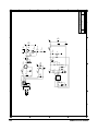
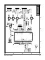


![[SPT-3000] e](http://vs1.manualzilla.com/store/data/005667089_1-a5f3766b3193f6552f250995926a69c5-150x150.png)