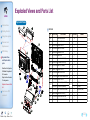
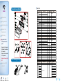
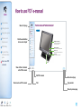
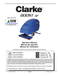
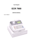
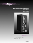
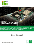
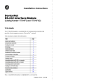
1
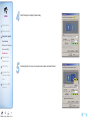
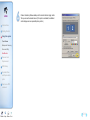
Unpacking
HOME
Introductions
Unpacking
Specification
Product overview
Getting Started
Using this system
Removal and
Replacement
BIOS Setup
Exploded View
and Replaceable
parts
<Main body>
<Mouse(Option)>
<Keyboard(Option)>
How to use PDF
e-manual
<Quick manual >
Content H e l p Printer E x i t
<Magnetic Dallas(Option)>
<Power Cable / Adoptor>
1-2
HOME
Introductions
Unpacking
Specification
Product overview
Getting Started
General Specification
Dimension(mm)
Weight
Processor
P
Chip Sets
HDD
How to use PDF
e-manual
I/O Interface
OS
(Operating System)
Content H e l p Printer E x i t
CPU : Intel Atom Processor N270 1.6GHz(Onboard) Without FAN
Northbridge : Intel 945GSE
Southbridge : Intel ICH7M
2.5" SATA Type
Serial(RS-232) Connector :
BIOS Setup
Exploded View
and Replaceable
parts
5.8 Kg
FSB : 533MHz
Using this system
Removal and
Replacement
387mm(W) × 278mm(L) × 340mm(H)
D-SUB 9Pin x 3(COM1,3,4) + RJ45 Port x 1(COM5)
COM1,3,4,5
Board DIP Switch Setting)
, , , --> 5V or 12V Output(Main
p (
g)
Serial(RS-422/485) Connector : D-SUB 9Pin x 1(COM1 Common Use : BIOS Setting)
Parallel Connector : D-SUB 25Pin x 1
USB 2.0 Connector : Left Side x 1, Rear Side x 4
LAN Connector : RJ45 Port x 1(8Pin)
Cash Drawer Connector : RJ11 Port x 1(6Pin)
VGA Connector : VGA Port x 1(15pin)
Audio Connector : Line out x 1, MIC x 1
Windows XP / 2000 / WEPOS / …
Main Memory
DDR2 533/667/800 SO-DIMM Slot, (Up to 2GB)
Booting Device
HDD, External CD/DVD-ROM Drive, USB Memory
1-3
BIOS
HOME
Introductions
Display
Unpacking
Specification
Touch Panel
Power Supply
100W Adapter
AC INPUT : AC 100~240V / 50~60Hz
DC OUTPUT : 12V /8.33A
Using this system
Removal and
Replacement
15" TFT LCD, LVDS Interface
Resolution & Colors : 1024x768(XGA), 16.2M(RGB) Color
Contrast Ratio : 450 : 1
Viewing Angle(H-V) : 150˚ / 130˚ (Left : 75˚, Right : 75˚, Up : 70˚, Down : 60˚)
Backlight Type : 2-CCFL
BacklightBrightness : 250 cd/㎡
Backlight MTBF : 50,000hrs
15" 5-Wire Resistive Type
Type : Serial COM6
Transparency : 80%
Surface Hardness : 3H
Hitting Life : 35million times
Product overview
Getting Started
AMI(Amerian Megatrends,
Megatrends Inc.)
Inc ) BIOS
BIOS Setup
Exploded View
and Replaceable
parts
How to use PDF
e-manual
Optional Specification
Customer Display
MSR
(Magnetic Stripe Reader)
Read Track : ISO Track 2&3 or ISO Track 1&2
Interface : USB
Performance : 10~150CM/Sec
/
Head Reliability : 500,000 times
Error Rate : Less than 0.5%
Wall Mount
Wall Mountable
Dallas Key
Magnet Type
Cash Drawer
Content H e l p Printer E x i t
20Char × 2Line,
2Line 5 × 7 Dot VFD or
256 × 32 Graphic Dot, 15" TFT LCD, XGA(1024 ×768)
RJ11 Port(6pin)
x 1,
12V or 24V (selection is possible)
1-4
Features names of Functions and each part
HOME
Introductions
Front View
Unpacking
Specification
Product overview
Getting Started
Using this system
MSR(Magnetic Stripe Reader)
Removal and
Replacement
Card (Credit Card, Loyalty Card and so on)
can be recognized for transaction.
BIOS Setup
Card Recognition Light
Exploded View
and Replaceable
parts
When the card is swiped correctly, the light will be lit.
How to use PDF
e-manual
Power Light
Hard Drive Light
When the Hard Drive is in operation, the light will be lit.
When the system is on, the light will be lit.
STAND
Content H e l p Printer E x i t
1-6
Bottom View
HOME
Introductions
Unpacking
Specification
Product overview
Getting Started
RJ45 LAN Port
Using this system
Removal and
Replacement
BIOS Setup
Exploded View
and Replaceable
parts
Microphone Port
RJ11 Cash Drawer Port
Customer Display Port
DC Power Supply Port
USB Port
Dual Monitor Port
Serial Port
DC Power Output Port
How to use PDF
e-manual
CF CARD
Audio Port
Content H e l p Printer E x i t
Parallel Port
1-7
..Rear View
HOME
USB
Introductions
USB Devices can be used through this
port, i.e. USB scanner, USB Keyboard,
USB Printer, etc.
Unpacking
Specification
Product overview
Getting Started
CUSTOMER DISPLAY(CDP)
This shows the amount which Customers
have to pay
SD CARD SLOT
SD Card, MMC Card can be used.
(Option)
Using this system
POWER BUTTON
Removal and
Replacement
Turns On-Off your system
BIOS Setup
LCD BRTGHTNESS
Screen Brightness can be altered.
Exploded View
and Replaceable
parts
How to use PDF
e-manual
ANGLE ADJUSTMENT LEVER
Angle can be altered between 20 ~ 90 degree.
DUAL MONTITOR EXPANSION COVER
Content H e l p Printer E x i t
DUMMY
1-8
Safety Instructions
HOME
● Read the safety instructions carefully and thoroughly. All cautions and warnings on the equipment or user’s manual should be noted.
● Lay this equipment on a stable surface before setting it up.
Introductions
● Keep this equipment away from humidity and high temperature.
Getting Started
● Make sure the power voltage is within safety range and has been adjusted properly to the value of 100~240V before connecting
the equipment to the power outlet.
Safety Instructions
Removing the Cover
Cable
● Always keep the strong magnetic or electrical objects away from the equipment.
Connecting the
External Device
● Always unplug the power cord before conecting any
the equipment or cause an electrical shock.
Turning the System
On and Off
● The openings on the enclosure are used for air convection and to prevent the equipment from overheating. Do not cover the openings.
Using this system
Removal and
Replacement
BIOS Setup
Exploded View
and Replaceable
parts
External Devices. Never pour liquid into the opening that could damage
Note !
▶
Adjust the angle of Display.
90。
Screen angle can be adjusted for best viewing.
50。[STANDARD ANGLE]
20。
How to use PDF
e-manual
Content H e l p Printer E x i t
2-1
Before connecting Peripherals
HOME
Introductions
Getting Started
Safety Instructions
Connecting Peripherals
Remove Cover Cable
❶ In case the screws of Cover Cable are fixed, remove them first.
Removing the Cover
Cable
Hook of Cover Cable
Connecting the
External Device
Turning the System
On and Off
Using this system
❷ After removing screws, press hook of Cover Cable and remove.
Removal and
Replacement
BIOS Setup
Exploded View
and Replaceable
parts
How to use PDF
e-manual
Content H e l p Printer E x i t
2-2
Remove Cable Tidy Dummy
HOME
Remove Cable Tidy Dummy by using (-) shaped driver. Depending upon the places,
the system can be used while Cable Tidy Dummy is removed.
Introductions
Getting Started
Safety Instructions
Removing the Cover
Cable
Connecting the
External Device
Cable Tidy Dummy
Turning the System
On and Off
Using this system
Removal and
Replacement
BIOS Setup
Dual Monitor Expansion Cover
In case there is not enough space for connecting Dual Monitor or Customer Display (Pole),
Dual Monitor Expansion Cover can be removed.
Exploded View
and Replaceable
parts
How to use PDF
e-manual
Dual Monitor Expansion
Cover
Content H e l p Printer E x i t
2-3
Connecting Peripherals
HOME
Introductions
Getting Started
The I/O ports on the POS-System allow you to connect peripheral devices. All device listed here are for reference only.
Connecting keyboard & mouse
Connect PS/2 type keyboard & mouse.
Safety Instructions
Removing the Cover
Cable
Connecting the
External Device
Turning the System
On and Off
Using this system
Removal and
Replacement
Connecting Printer
BIOS Setup
QBIG PC POS supports parallel, serial & USB typed printers.
Connect desired type of printer cable.
Exploded View
and Replaceable
parts
How to use PDF
e-manual
Content H e l p Printer E x i t
Note !
System supplies upto 24V & 2.3A. In case the printer requires
above mentioned voltage & current, the power adapter should
be used.
Power Cable
for Printer
<Receipt Printer>
2-4
Connecting devices which uses the serial port
HOME
Connect barcode scanner etc. to the serial port.
Introductions
Getting Started
PORT
5V
12V
Safety Instructions
COM1
○
○
COM3
○
○
X
COM4
○
○
X
Removing the Cover
Cable
Connecting the
External Device
(RS422/RS485)
<Barcode Scanner>
5V
12V
Turning the System
On and Off
Using this system
Removal and
Replacement
Connecting RJ-11 Cash Drawer
Use RJ-11 port when Cash Drawer is desired & used
(Use SAM4S Cash Drawer).
BIOS Setup
Exploded View
and Replaceable
parts
How to use PDF
e-manual
<Cash Drawer>
Content H e l p Printer E x i t
2-5
Connecting RJ-45 LAN cable
HOME
RJ-45 LAN or Internet enabled cable can be connected.
It supports 10Mbps/100Mbps.
Introductions
<LAN Hub>
Getting Started
Safety Instructions
Removing the Cover
Cable
Connecting the
External Device
Turning the System
On and Off
Using this system
Removal and
Replacement
Connecting USB Device
USB connector is located both the side of LCD panel and the back of the
system so USB devices can be connected at both locations. USB hub can
be used to connect various USB devices which includes keyboard, mouse,
CCD camera and printer etc. (separate device drivers may be required).
BIOS Setup
Exploded View
and Replaceable
parts
How to use PDF
e-manual
Content H e l p Printer E x i t
<Mouse>
<Keyboard>
<CCD Camera>
2-6
HOME
Connecting DC power supply cable.
Connecting DC power supply cable to the bottom of system.
(Free Voltage system adapter is used. Both 100V and 220V can be used.)
Introductions
Getting Started
Safety Instructions
Removing the Cover
Cable
Connecting the
External Device
Note !
▶ QBig Adapter from SAM4S should only be used. Never
use the adapter with similar specification or shaped .
Turning the System
On and Off
Using this system
Removal and
Replacement
BIOS Setup
Exploded View
and Replaceable
parts
How to use PDF
e-manual
Content H e l p Printer E x i t
2-7
System On/Off
HOME
Introductions
Getting Started
Safety Instructions
Removing the Cover
Cable
Connecting the
External Device
Turning the System
On and Off
System On
After installation of system, proceed to power on the system with following steps.
1
Power up the peripherals which are connected with the system.
2
Press the power button placed at the left side of system LCD (Open the power button cover and press).
3
PWR light is to be lit at the right bottom of the LCD front.
Using this system
Removal and
power bottom
Replacement
BIOS Setup
Exploded View
and Replaceable
parts
power light
4
Windows initial screen can be seen after a while.
How to use PDF
e-manual
Content H e l p Printer E x i t
2-8
System Off
HOME
Introductions
Getting Started
1
All applications should be off after saving files in the designated place.
2
Press <Start> button and select 'Turn off Computer' on popup menu.
3
System will be shut down when <Turn Off> button is clicked.
Safety Instructions
Removing the Cover
Cable
Connecting the
External Device
Turning the System
On and Off
Using this system
Removal and
Replacement
BIOS Setup
Exploded View
and Replaceable
parts
How to use PDF
e-manual
Content H e l p Printer E x i t
2-9
Touch Screen
Recalibrate if it is not accurate on touch points.
HOME
Click the right button of mouse on 'PM' icon of Windows tray icons.
Introductions
And select 'Control Panel' on popup menu.
Getting Started
Using this system
Touch Screen
Backup and Recovery
Driver and Utility
Dual Monitor
Removal and
Replacement
BIOS Setup
Check Out
Check
OutTouch
TouchScrrraemememedmdfmdm,drrreen
Screen
1
'PenMount Control Panel' dialog appears.
2
Click the 'Tools' tab and check out whether or not 'Advanced Calibration'
option box is yellow-marked. If it is not yellow, click the 'Advanced
Calibration' button and return to 'Device' tab.
Exploded View
and Replaceable
parts
How to use PDF
e-manual
Content H e l p Printer E x i t
3-1
i
bration
Touch
Screen Calibration
HOME
1
Double-click 'PenMount 9000 RS232' on 'Device' Tab.
2
On 'Calibrate' tab, select the number '25' of Advanced Mode combo-box list if it is possible.
And then click the 'Advanced Calibration' button.
(The number of box is higher and higher, calibration will be more accurate.)
Introductions
Getting Started
Using this system
Touch Screen
Backup and Recovery
Driver and Utility
Dual Monitor
Removal and
Replacement
BIOS Setup
Exploded View
and Replaceable
parts
How to use PDF
e-manual
Content H e l p Printer E x i t
3-2
HOME
Introductions
Getting Started
3
Click the red point about 2 seconds on a calibration screen. Calibration procedure will be proceeded with following messages.
Caution
Ball point pen or sharpness tools may damage to surface of touch screen.
Using this system
Touch Screen
Backup and Recovery
Driver and Utility
Dual Monitor
Removal and
Replacement
BIOS Setup
Exploded View
and Replaceable
parts
How to use PDF
e-manual
Content H e l p Printer E x i t
3-3
Note !
HOME
For using the Touch Screen on Multi-monitor.
❶ Check 'Multiple Monitor Support' box on 'Multiple Monitors' tab.
❷ Click <Map Touch Screens> button.
❸ Click <OK> button on 'Mapping' message
. box.
❹ If you want to use touchable screen of current monitors, you shoud
touch the screen. If or not,press 'S' to skip.
Introductions
Getting Started
Using this system
Touch Screen
Backup and Recovery
Driver and Utility
Dual Monitor
Removal and
Replacement
BIOS Setup
Exploded View
and Replaceable
parts
How to use PDF
e-manual
For more detailed information about using dual monitor, refer to 'Dual Monitor' pages.
Content H e l p Printer E x i t
3-4
Winlon (Backup & Recovery)
WinClon make the system backup or restored. User can restore the system to ‘the
manufactured state’ with WinClon’s initial state image. And user can backup the
system with its current state (Create WinClon’s recent state image).
HOME
Caution
Introductions
Getting Started
Recovery proceeds with system partition (C Drive). Please backup the data in the system (C Drive) before the recovery. User should prepare the system connected with a keyboard,
because touch screen does not work during Backup & Recovery.
Using this system
Touch Screen
System Recovery
Backup and Recovery
Driver and Utility
Dual Monitor
1
Press keyboard’s <F11> key when ‘F11 to WinClon’ appears on
the screen.
2
When a below screen appears, press keyboard’s <F3> key.
Removal and
Replacement
BIOS Setup
Exploded View
and Replaceable
parts
How to use PDF
e-manual
Content H e l p Printer E x i t
3-5
5HFRYHU\RQ:LQGRZV0RGH
3
Click ‘OK’ button.
4
User can check the progress.
5
Check the message and click ‘Ok’ button, after the restore is successfully
completed. The system will be restarted automatically.
HOME
Introductions
Getting Started
Using this system
Touch Screen
Backup and Recovery
Driver and Utility
Dual Monitor
Removal and
Replacement
BIOS Setup
Exploded View
and Replaceable
parts
How to use PDF
e-manual
Content H e l p Printer E x i t
3-6
System Backup
HOME
1
Press keyboard’s <F11> key when ‘F11 to WinClon’ appears on the screen.
3
Click ‘OK’ button.
2
When a below screen appears, press keyboard’s <F10> key.
4
User can check the progress.
Introductions
Getting Started
Using this system
Touch Screen
Backup and Recovery
Driver and Utility
Dual Monitor
Removal and
Replacement
BIOS Setup
Exploded View
and Replaceable
parts
How to use PDF
e-manual
Content H e l p Printer E x i t
3-7
5
HOME
Check the message and click ‘Ok’ button, after the backup is successfully completed.
The system will be restarted automatically.
Introductions
Getting Started
Using this system
Touch Screen
Backup and Recovery
Driver and Utility
Dual Monitor
Note!
Restore Recent State [F2]
User can restore the system to ‘the latest backup state’ with ‘WinClon’s recent state’ image
Restore Initial State [F3]
User can restore the system to ‘the manufactured state’ with ‘WinClon’s initial state’ image
Removal and
Replacement
BIOS Setup
Exploded View
and Replaceable
parts
How to use PDF
e-manual
Content H e l p Printer E x i t
3-8
POS Driver and Utility
HOME
Drivers and utilities are in the folder that the directory is 'C:\Util_Driver\'.
Introductions
Getting Started
Using this system
Touch Screen
Backup and Recovery
Driver and Utility
Dual Monitor
Removal and
Replacement
BIOS Setup
Exploded View
and Replaceable
parts
How to use PDF
e-manual
'ULYHUV
Driver installation files Audio, Video
LAN, Chipsetand Touch screen.
Mother Board Manual
System Manual
Utility
Content H e l p Printer E x i t
3-9
POS Utility
HOME
C:\Util_Driver\Utility
Introductions
Getting Started
Using this system
Touch Screen
Backup and Recovery
Driver and Utility
Dual Monitor
Removal and
Adobe Reader
MiniPrinter
Ellix20 installation file
MS Excel Viewerv
Pos Utility
Replacement
BIOS Setup
Exploded View
and Replaceable
parts
How to use PDF
e-manual
MSR
MSR setup utility
OPOS
OPOS driver file
Self Test Program
Test utility for peripherals of POS
VFD
Dll, Test utility for using VFD
Content H e l p Printer E x i t
33-10
OPOS Driver
HOME
OPOS or OLE for Retail POS consists of an architecture for win32-based POS device access.
Introductions
Getting Started
Using this system
The current OPOS driver has been developed in accordance with OPOS Specification Version 1.10. and continues to support the OPOS version.
Supporting OS : Windows 2000, Windows XP, WEPOS
Available Pheripherals
Touch Screen
LineDisplay : QLD202C
Backup and Recovery
POSPrinter : ELLIX Series
Driver and Utility
Dual Monitor
The location of installation file
Removal and
The file is shipped on the hard disk.
Replacement
(C:\Util_Driver\Utility\Pos Utility\OPOS)
BIOS Setup
Exploded View
and Replaceable
parts
The way of installation
❶ Run 'SAM4S OPOS Installer.exe'.
❷ During OPOS Driver installation, all of components are automatically registered and set up properly for system composition.
How to use PDF
e-manual
Content H e l p Printer E x i t
3-11
Dual Monitor
HOME
Additional monitor can be connected to the VGA port at the bottom of QBIG.
The system supports 'dual monitors' that is using two monitors for one system. Sub-monitor can be displayed a screen copied a main-monitor's Windows desktop
or can be displayed a screen extended Windows desktop. If you set 'dual monitors', you should calibrate touch screen again.
Introductions
Getting Started
Using this system
Touch Screen
Backup and Recovery
Driver and Utility
Dual Monitor
Removal and
Connect to external monitor when the system is turned off.
(If 'connector protecting cover' is seperated from the bottom
of system, VGA connector is shown.)
❶ Connect to external monitor when the system is turned off.
❷ Connect a power cable to external monitor.
Replacement
BIOS Setup
Press a power button of the system and the external monitor.
Exploded View
and Replaceable
parts
How to use PDF
e-manual
Content H e l p Printer E x i t
Click the right button of mouse on Windows desktop screen,
and select 'properties' from a popup menu.
3-12
HOME
Select 'Settings' tab on 'Display Properties' dialog.
Introductions
Getting Started
Using this system
Touch Screen
Backup and Recovery
Driver and Utility
Dual Monitor
Removal and
Replacement
BIOS Setup
Click the right button of mouse on the second monitor's indicator and select 'Attached'.
Exploded View
and Replaceable
parts
How to use PDF
e-manual
Content H e l p Printer E x i t
3-13
HOME
Check an 'Extend my Windows desktop onto this monitor' and click <Apply> button.
Then you can see the extended screen. (If this option is unchecked, the additional
monitor displays a screen copied with primary monitor.)
Introductions
Getting Started
Using this system
Touch Screen
Backup and Recovery
Driver and Utility
Dual Monitor
Removal and
Replacement
BIOS Setup
Exploded View
and Replaceable
parts
How to use PDF
e-manual
Content H e l p Printer E x i t
3-14
Note !
HOME
Introductions
Getting Started
How to check dual monitor's setting
If 'dual monitors' doesn't work properly, refer to the following procedure.
method1
방법1
Check the BIOS Setup
Make sure that 'Chipset > North Bridge Chipset Configuration
방법2
method2
Using this system
Video Function Configuration
Boot Display Device' menu is selected as 'CRT+LVDS'.
❶ Click the right button of mouse on Windows desktop screen and select 'Graphic Properties' menu.
❷ Select 'Intel(R) Dual Display Clone' at 'Multiple Display' menu.
Touch Screen
Backup and Recovery
Driver and Utility
Dual Monitor
Removal and
Replacement
BIOS Setup
Exploded View
and Replaceable
parts
method3
방법3
❶ Click the right button of mouse on Windows desktop screen and select 'Graphic Options' menu.
❷ Select 'Graphic Options > Output To > Intel(R) Dual Display Clone > Notebook + Monitor'.
How to use PDF
e-manual
Content H e l p Printer E x i t
3-15
HOME
System Dismantle & Reassemble
Introductions
Getting Started
System Dismantle
Using this system
Removal and
Replacement
System Disassemble
System Reassemble
1
Make sure the system & peripherals power are off.
2
Take off the connector cab from the bottom of system in case it is fixed with screws.
3
Disconnect cables for peripherals & DC power input jack from the system.
Memory Module
Hard Disk Drive
Magnetic Stripe Reader
(MSR)
Internal Speaker
SD Card & USB Board
Inverter Module
Touch & MSR Board
LED Board
Power Board
Main Board
Please note!
Touch Panel and TFT-LCD
Magnetic Dallas (Option)
BIOS Setup
Exploded View
and Replaceable
parts
When disconnecting DC power supply
jack, the neck point should gently be
pulled out.
How to use PDF
e-manual
Content H e l p Printer E x i t
4-1
HOME
4
CDP should be rotated as the direction shown in the figure
and press ‘PUSH’ area with hands.
5
CDP should be separated as the arrow shown and its connector
should be disconnected.
6
Lay the system while preventing LCD panel is being damaged.
7
Dismantle the stand, which is fixed with levers and it can be rotated.
Introductions
Getting Started
Using this system
Removal and
Replacement
System Disassemble
System Reassemble
Memory Module
Hard Disk Drive
Magnetic Stripe Reader
(MSR)
Internal Speaker
SD Card & USB Board
Inverter Module
Touch & MSR Board
LED Board
Power Board
Main Board
Touch Panel and TFT-LCD
Magnetic Dallas (Option)
BIOS Setup
Exploded View
and Replaceable
parts
How to use PDF
e-manual
Content H e l p Printer E x i t
4-2
HOME
8
Stand can be dismantled as the figure shown.
10
System dummy back panel can be dismantled
with the aid of figure.
Introductions
9
Refer to the figure, unscrew, release lock lever and the system back
panel should be taken apart.
Getting Started
Using this system
Removal and
Replacement
System Disassemble
System Reassemble
Memory Module
Hard Disk Drive
Magnetic Stripe Reader
(MSR)
Internal Speaker
SD Card & USB Board
Inverter Module
Touch & MSR Board
LED Board
Power Board
Main Board
Touch Panel and TFT-LCD
Magnetic Dallas (Option)
BIOS Setup
Exploded View
and Replaceable
parts
How to use PDF
e-manual
System Reassemble
It can be done going backwards of dismantling, and peripherals cable & DC power input jack is connected to the mains power.
Content H e l p Printer E x i t
4-3
HOME
Introductions
Getting Started
Using this system
Removal and
Replacement
System Disassemble
Upgrading Memory Module
In case, the user requires to expand the capacity of system memory, the specification of memory should first be checked. Memory size can be
decided a maximum of 2GB, depending upon the specification of its main board. Once the memory is installed, BIOS automatically recognizes
the memory type, capacity and speed.
1
※Cables for power & peripherals should be disconnected prior to system disassemble.
System Reassemble
Memory Module
Hard Disk Drive
Magnetic Stripe Reader
(MSR)
System should be turned off for expanding memory.
2
System back cover should be taken off, referring System Dismantle.
3
Install new memory as shown in the figure and tighten them with levers at both ends.
Lever
Internal Speaker
SD Card & USB Board
Inverter Module
Touch & MSR Board
LED Board
Power Board
Main Board
Touch Panel and TFT-LCD
Magnetic Dallas (Option)
BIOS Setup
Exploded View
and Replaceable
parts
How to use PDF
e-manual
Content H e l p Printer E x i t
4-4
HOME
Replacing Hard Disk Drive
Introductions
Getting Started
Using this system
Removal and
Replacement
2.5 inch SATA type can only be installed, hence the hard drive type should be checked before purchase.
1
Before system dismantle, save data, turn off the system and all cables & mains power should be disconnected.
2
Disconnect system back cover, refer to the system dismantle contents.
3
Disconnect power & data cable of hard disk drive.
4
Remove 3 screws which hold HDD bracket.
System Disassemble
System Reassemble
Memory Module
Hard Disk Drive
Magnetic Stripe Reader
(MSR)
Internal Speaker
SD Card & USB Board
Inverter Module
Touch & MSR Board
LED Board
Power Board
Main Board
Touch Panel and TFT-LCD
Magnetic Dallas (Option)
Screw
Cable
BIOS Setup
Exploded View
and Replaceable
parts
How to use PDF
e-manual
Content H e l p Printer E x i t
4-7
HOME
5
Remove bracket from the hard disk drive as shown in the figure.
6
Remove screws from the hard disk drive as shown in the figure.
7
Assemble it in the opposite way of dismantling and connect peripheral cables & DC power input jack.
8
Press power button and check system setup menu for making sure the hard disk drive is correctly connected.
Introductions
Getting Started
Using this system
Removal and
Replacement
System Disassemble
System Reassemble
Memory Module
Hard Disk Drive
Magnetic Stripe Reader
(MSR)
Internal Speaker
SD Card & USB Board
Inverter Module
Touch & MSR Board
LED Board
Power Board
Main Board
Touch Panel and TFT-LCD
Magnetic Dallas (Option)
BIOS Setup
Exploded View
and Replaceable
parts
How to use PDF
e-manual
Content H e l p Printer E x i t
4-8
HOME
Magnetic Stripe Reader(MSR) Removal
Introductions
Getting Started
1
Remove system back cover (refer to System Dismantle).
2
Disconnect MSR (Magnetic Stripe Reader)
cable.
3
Remove 3 screws which hold MSR bracket.
4
Remove tape which hold MSR bracket.
5
Remove MSR bracket while referring to the figure.
MSR cable
Using this system
Removal and
Replacement
System Disassemble
System Reassemble
Memory Module
Hard Disk Drive
Magnetic Stripe Reader
(MSR)
Internal Speaker
Tape
SD Card & USB Board
Inverter Module
Touch & MSR Board
LED Board
Power Board
Main Board
Touch Panel and TFT-LCD
Screw
Magnetic Dallas (Option)
BIOS Setup
Exploded View
and Replaceable
parts
How to use PDF
e-manual
Content H e l p Printer E x i t
4-9
HOME
Other Main Components Removal
Introductions
Getting Started
Using this system
Removal and
Replacement
Internal
Speaker
내장형 스피커
분리 Removal
1
Remove system back cover (refer to System Dismantle).
2
Disconnect speaker cable.
3
Remove speaker while pressing the hook which holds the speaker.
System Disassemble
System Reassemble
Note !
When external speaker is connected to be in use, the internal speaker
cable should be disconnected in case the internal speaker does not
wish to be in operation.
Memory Module
Hard Disk Drive
Magnetic Stripe Reader
(MSR)
Internal Speaker
SD Card & USB Board
Inverter Module
Touch & MSR Board
LED Board
Power Board
Main Board
Touch Panel and TFT-LCD
Magnetic Dallas (Option)
BIOS Setup
Exploded View
and Replaceable
parts
How to use PDF
e-manual
Content H e l p Printer E x i t
4-10
HOME
Introductions
Getting Started
Using this system
Removal and
Replacement
Remove SD card USB board
1
Remove system back cover (refer to System Dismantle).
2
Remove screws which hold the bracket.
3
Remove SD card USB board while lifting up the bracket.
System Disassemble
System Reassemble
Memory Module
Hard Disk Drive
Magnetic Stripe Reader
(MSR)
Internal Speaker
SD Card & USB Board
Inverter Module
Touch & MSR Board
LED Board
Power Board
Main Board
Touch Panel and TFT-LCD
Note !
Please take extra care that the position of cable should be correct
when reassemble it.
Magnetic Dallas (Option)
BIOS Setup
Exploded View
and Replaceable
parts
How to use PDF
e-manual
Content H e l p Printer E x i t
4-11
HOME
Introductions
Getting Started
Using this system
Removal and
Replacement
Remove Inverter
1
Remove system back cover (refer to System Dismantle).
2
Remove inverter while pressing hook inside the inverter and push forward gently (refer to the figure).
System Disassemble
System Reassemble
Memory Module
Hard Disk Drive
Magnetic Stripe Reader
(MSR)
Internal Speaker
SD Card & USB Board
Inverter Module
Touch & MSR Board
Hook
LED Board
Power Board
Main Board
Touch Panel and TFT-LCD
Magnetic Dallas (Option)
BIOS Setup
Exploded View
and Replaceable
parts
How to use PDF
e-manual
Content H e l p Printer E x i t
4-12
HOME
Introductions
Getting Started
Using this system
Removal and
Replacement
System Disassemble
System Reassemble
Memory Module
Remove Touch MSR board
1
Remove system back cover (refer to System Dismantle).
2
Remove inverter while referring to Remove Inverter.
3
Disconnect all cables to Touch MSR board.(Touch, MSR, LED, ETC)
4
Remove Touch MSR board after undoing screws (2EA) which connect to the display bracket.
Hard Disk Drive
Magnetic Stripe Reader
(MSR)
Internal Speaker
SD Card & USB Board
Dallas Cable
Inverter Module
Touch & MSR Board
LED Cable
LED Board
Screw
Power Board
MSR Cable
Main Board
Touch Panel and TFT-LCD
Magnetic Dallas (Option)
BIOS Setup
Cable
Touch Cable
Exploded View
and Replaceable
parts
How to use PDF
e-manual
Content H e l p Printer E x i t
4-13
HOME
Introductions
Getting Started
Using this system
Removal and
Replacement
System Disassemble
Remove LED board
Remove DSUB board
1
Remove system back cover (refer to System Dismantle).
1
Remove system back cover (refer to System Dismantle).
2
Disconnect cables which connect LED board.
2
Disconnect cables which connect DSUB board.
3
Remove LED board after undoing screws (2EA) which hold LED board.
3
Remove DSUB board.
System Reassemble
Memory Module
Remove JOINT board
DSUB board
Hard Disk Drive
Magnetic Stripe Reader
(MSR)
Internal Speaker
SD Card & USB Board
Inverter Module
LED board
& cable
DSUB cable
Touch & MSR Board
1
Remove system back cover (refer to System Dismantle).
2
Remove JOINT board.
LED Board
Power Board
Main Board
Touch Panel and TFT-LCD
Magnetic Dallas (Option)
BIOS Setup
Exploded View
and Replaceable
parts
JOINT board
How to use PDF
e-manual
Content H e l p Printer E x i t
4-14
HOME
Remove Power board
Introductions
Getting Started
Using this system
Removal and
Replacement
System Disassemble
1
Remove system back cover (refer to System Dismantle).
2
Disconnect cables for HDD and remove HDD module (refer to System Dismantle).
3
Disconnect cables for speaker and remove SD board (refer to System Dismantle).
4
Disconnect all cables to Power board.
5
Remove Power board after undoing screws (6EA) which hold Power board.
System Reassemble
Memory Module
Hard Disk Drive
Magnetic Stripe Reader
(MSR)
Internal Speaker
SD Card & USB Board
Inverter Module
Touch & MSR Board
LED Board
HDD Module
Power Board
Speaker Cable
Main Board
SD Card board
Touch Panel and TFT-LCD
Power board
Screw
Joint board
Magnetic Dallas (Option)
BIOS Setup
Exploded View
and Replaceable
parts
How to use PDF
e-manual
Content H e l p Printer E x i t
4-15
HOME
Introductions
Getting Started
Using this system
Removal and
Replacement
System Disassemble
Remove Main board
1
Remove system back cover (refer to System Dismantle).
2
Remove inverter while referring to Remove Inverter.
3
Disconnect all cables to main board.
4
Remove main board after undoing screws to main board and pushing the direction of arrow.
System Reassemble
Memory Module
Hard Disk Drive
Magnetic Stripe Reader
(MSR)
Internal Speaker
HDD Module
2
SD Card & USB Board
Inverter Module
Touch & MSR Board
LED Board
Main board
Inverter board
1
Power Board
Main Board
Touch Panel and TFT-LCD
Magnetic Dallas (Option)
BIOS Setup
Screw
Exploded View
and Replaceable
parts
How to use PDF
e-manual
Content H e l p Printer E x i t
4-17
HOME
Remove Touch panel
Introductions
Getting Started
Using this system
Removal and
Replacement
System Disassemble
System Reassemble
Memory Module
Hard Disk Drive
Warning!
※ It appears to happen defectives while disconnecting LCD and touch panel due to dust or mis-handling. Please get correct service from approved service center.
1
Remove system back cover (refer to System Dismantle).
2
Disconnect cables as shown in the figure and undo screws.
Magnetic Stripe Reader
(MSR)
Internal Speaker
SD Card & USB Board
Inverter Module
Touch & MSR Board
Dallas cable
LED Board
Power Board
Main Board
Touch Panel and TFT-LCD
Magnetic Dallas (Option)
LED cable
MSR cable
BIOS Setup
Exploded View
and Replaceable
parts
How to use PDF
e-manual
Content H e l p Printer E x i t
Touch cable
4-19
HOME
3
Remove touch panel while holding bracket and lift up the display assembly.
Introductions
Getting Started
Using this system
Removal and
Replacement
Hand
Hand
System Disassemble
System Reassemble
Memory Module
Hard Disk Drive
Magnetic Stripe Reader
(MSR)
Internal Speaker
SD Card & USB Board
Inverter Module
Touch & MSR Board
LED Board
Power Board
Main Board
Touch Panel and TFT-LCD
Warning!
▶ Be careful in case of any damage occurred to cables.
▶ Touch panel may separate from LCD panel all of a sudden due to vacuum condition
in between touch panel and LCD.
▶ Be careful in case of any breakage and injury.
▶Be careful in case of any dust being stuck into the surface of LCD or touch panel and
scratch to them.
Magnetic Dallas (Option)
BIOS Setup
Exploded View
and Replaceable
parts
How to use PDF
e-manual
Content H e l p Printer E x i t
4-20
HOME
4
Disconnect LVDS cable and LCD cable. Unfold disconnected cables, avoid interferences with other cables.
Introductions
Getting Started
LVDS Cable
Using this system
Removal and
Replacement
LCD Cable
System Disassemble
System Reassemble
Memory Module
Hard Disk Drive
Magnetic Stripe Reader
(MSR)
Internal Speaker
SD Card & USB Board
Inverter Module
5
Undo screws (4EA) on the side of display bracket.
Touch & MSR Board
LED Board
Power Board
Main Board
Touch Panel and TFT-LCD
Magnetic Dallas (Option)
BIOS Setup
Exploded View
and Replaceable
parts
How to use PDF
e-manual
Content H e l p Printer E x i t
4-21
HOME
6
Remove LVDS cable which is connected to LCD after the bracket is lifted while preventing LVDS cable is not put in between.
Introductions
Getting Started
Using this system
Removal and
Replacement
System Disassemble
System Reassemble
Memory Module
Hard Disk Drive
Magnetic Stripe Reader
(MSR)
LVDS Cable
Internal Speaker
SD Card & USB Board
Inverter Module
Touch & MSR Board
LED Board
Power Board
Main Board
Touch Panel and TFT-LCD
Magnetic Dallas (Option)
BIOS Setup
Exploded View
and Replaceable
parts
How to use PDF
e-manual
Content H e l p Printer E x i t
4-22
HOME
Introductions
Getting Started
Using this system
Removal and
Replacement
System Disassemble
Remove Dallas (Option)
1
Remove system back cover (refer to System Dismantle).
2
Disconnect cables which connect to its board.
3
Remove Dallas holder while rotating it in clock-wise.
2
System Reassemble
Memory Module
Hard Disk Drive
Magnetic Stripe Reader
(MSR)
Internal Speaker
1
SD Card & USB Board
Inverter Module
Touch & MSR Board
LED Board
Power Board
4
Remove Dallas holder while rotating it in clock-wise.
Main Board
Touch Panel and TFT-LCD
Magnetic Dallas (Option)
BIOS Setup
Exploded View
and Replaceable
parts
How to use PDF
e-manual
Content H e l p Printer E x i t
4-23
System Set up
System setup means that the system configuration information is memorized on BIOS Setup Utility
It is also saved in a special area of memory called CMOS ROM.
HOME
Introductions
Getting Started
Using this system
Removal and
Entering the Setup Program
Turn
on the system
and the Program
system will show 'Press <DEL> to enter SETUP' message.
Entering
the Setup
Press <DEL> or <Delete> to enter SETUP when this message shows up.
Replacement
BIOS Setup
System Set up
Exploded View
and Replaceable
parts
How to use PDF
e-manual
Cases of 'BIOS Setup' settings
ofHDD
'BIOS
settings
●Cases
Check the
typeSetup'
and capacity
after HDD replacement.
● Change booting sequence
● Reflect user's needs on the setup
.
● Set or change a password
.
Content H e l p Printer E x i t
A-1
Initial Setup Screen
HOME
Initial Setup Screens has menus as Main, Advanced, Boot, Security, Chipset, Power, Exit.
Introductions
Getting Started
Using this system
Removal and
Replacement
BIOS Setup
System Set up
Exploded View
and Replaceable
parts
How to use PDF
e-manual
Content H e l p Printer E x i t
Using Keys
If you press 'F1' key, you can see the simple explanation of keys.
A-2
HOME
Introductions
Getting Started
Using this system
Removal and
← : Select Screen
Select menus you want.
↑ , ↓ : Select Item
Move the cursor to select menu or option tab. On focused menu will be changed color to white.
+ , - : Change Option / Field
Use them for setting value.
Replacement
Enter : Go to Sub Screen
BIOS Setup
Some of menus include sub-menu. You can select sub-menu as clicking <Enter> key.
System Set up
Exploded View
and Replaceable
parts
How to use PDF
e-manual
PGDN : Next Page
Move to the next page.
PGUP : Previous Page
Move to the previous page.
HOME : Go to Top of Screen
END : Go to Bottom of Screen
F2/F3 : Change Colors
Change the BIOS font color with background color.
Content H e l p Printer E x i t
A-3
HOME
Introductions
Getting Started
Using this system
Removal and
F7 : Discard Changes
Abandon all changes.
F8 : Load Failsafe Defaults
In case of improper value input or system error caused by improper configuration setting, you can load default configuration value using this menu.
F9 : Load Optimal Defaults
Use this menu to load the BIOS default values for the minimal/stable performance for your system to operate.
Replacement
F10 : Save and Exit
BIOS Setup
Save changed value and exit setup program.
System Set up
Exploded View
and Replaceable
parts
ESC : Exit
Use for 'Exit' current page and return to its super-menu but 'Quit without saving' changes on Main Screen.
How to use PDF
e-manual
Content H e l p Printer E x i t
A-4
Main Menu
Use this menu for basic system configuration, such as time. date etc.
HOME
Introductions
Getting Started
Using this system
Removal and
Replacement
BIOS Setup
System Set up
Exploded View
and Replaceable
parts
How to use PDF
e-manual
BIOS Information, Processor, System MemoryDate(mm:dd:yy)
These items show the firmware and hardware specifications of your system. Read only.
System Time
The time format is <Hour> <Minute> <Second>.
System Date
The date formate is <Day>, <Month>, <Date>, <Year>.
Content H e l p Printer E x i t
A-5
Advanced Menu
Use this menu to set up the items of special enhanced features.
HOME
Introductions
Getting Started
Using this system
Removal and
Replacement
BIOS Setup
System Set up
Exploded View
and Replaceable
parts
How to use PDF
e-manual
CPU Configuration
These items show the advanced specifications of your CPU. Read only.
IDE Configuration
This setting specifies the operation mode of the onboard IDE controller.
Super IO Configuration
Configure SuperIO Chipset F71882F.
Content H e l p Printer E x i t
A-6
Hardware
Hardware Health
Health Configuration
First/Second/Third
Boot Device
HOME
Configure or monitor the hardware health.
Introductions
Getting Started
Using this system
BACPI
Configuration
ACPI
Configuration
Selects power on state for NumLock
Removal and
Replacement
BIOS Setup
USB Configuration
Configure the USB support.
System Set up
Exploded View
and Replaceable
parts
How to use PDF
e-manual
Content H e l p Printer E x i t
A-7
HOME
CPU Configuration
Introductions
MAX CPUID Valve Limit
Getting Started
The Max CPUID Value Limit BIOS feature allows you to circumvent problems
with older OS that don't support the Pentium 4 processor with Hyper-Threading
Using this system
Technology. When enable, the processor will limit the maximum CPUID input
value to 03h when queried, even if the processor supports a higher CPUID input
Removal and
value. When disabled, the processor will return the actual value.
Replacement
BIOS Setup
System Set up
Exploded View
and Replaceable
parts
How to use PDF
e-manual
Execute-Disable Bit Capability
Execute Disable Bit functionality can prevent certain classes of malicious "buffer
overflow" attacks when combined with a supporting OS . This functionality allows
the processor to classify areas in memory by where application code can execute
and where it can't. When a malicious worm attempts to insert code in the buffer,
the processor disables code execution, preventing damage or worm propagation.
Hyper Threading Technology
The processor uses HT technology to increase transaction rates and reduces enduser response times. The technology treats the two cores inside the processor as
two logical processors that can execute instructions simultaneously. In this way,
the system performance is highly improved. If you disable the function, the processor
will use only one core to execute the instructions. Please disable this item if your
OS doesn't support HT Function, or unreliablity and instability may occur.
Intel(R) Speedstep(tm) Tech
EIST (Enhanced Intel SpeedStep Technology) allows the system to dynamically
adjust processor voltage and core frequency, which can result in decreased
average power consumption and decreased average heat production.
Content H e l p Printer E x i t
A-8
HOME
Introductions
Getting Started
Using this system
Removal and
Replacement
BIOS Setup
IDE Configuration
ATA/DE Configuration
This setting specifies the operation mode of the onboard ATA/IDE controller.
Legacy IDE Channels
This setting specifies the IDE channels.
Hard Disk Write Protect
This option allows users to write protect boot sector on hard disk to protect
against viruses.
System Set up
IDE Detect Time Out(Sec)
Exploded View
and Replaceable
parts
This setting allows you to set the time out value for the BIOS to delay the
initialization of IDE devices.
How to use PDF
e-manual
Content H e l p Printer E x i t
ATA(PI) 80Pin Cable Detection
This BIOS feature allows you to control whether both IDE controller and IDE
device should be allowed to detect the type of IDE cable used.
A-9
HOME
Primary IDE Slave
Introductions
Type
Getting Started
Press PgUp/<+> or PgDn/<-> to select [Manual], [None] or [Auto] type.
Note that the specifications of your drive must match with the drive table.
Using this system
The hard disk will not work properly if you enter improper information for this
Removal and
Replacement
BIOS Setup
category. If your hard disk drive type is not matched or listed, you can use
[Manual] to define your own drive type manually.
LBA/Large Mode
Enabling LBA causes Logical Block Addressing to be used in place of
System Set up
Cylinders, Heads and Sectors
Exploded View
and Replaceable
parts
Block(Multl-Sector Transfer)
How to use PDF
e-manual
Any selection except Disabled determines the number of sectors transferred
per block.
PIO Mode
Indicates the type of PIO (Programmed Input/Output)
DMA Mode
Indicates the type of Ultra DMA
S.M.A.R.T
This allows you to activate the S.M.A.R.T.(Self-Monitoring Analysis & Reporting
Technology) capability for the hard disks. S.M.A.R.T is a utility that monitors your
disk status to predict hard disk failure.
32 Bit Date Transfer
Enables 32-bit communication between CPU and IDE device
Content H e l p Printer E x i t
A-10
HOME
Super IO Configuration
Introductions
Serial Port
Getting Started
(1/2/3/4/5/6 Address, Serial Port 1/2/3/4 IRQ)
Using this system
Removal and
Replacement
Select an address and a corresponding interrupt for the serial port.
Serial Port5 Mode
This setting specifies the serial port5 mode.
Parallel Port Address
BIOS Setup
Select an address for the parallel port.
System Set up
Watch Dog
Exploded View
and Replaceable
parts
You can enable the system watch-dog timer, a hardware timer that generates
either an NMI or a reset when the software that it monitors does not respond
as expected each time the watch dog polls it.
How to use PDF
e-manual
Content H e l p Printer E x i t
A-11
n
HOME
Hardware Health Configuration
Introductions
Chassic Intrusion
Getting Started
The field enables or disables the feature of recording the chassis intrusion
status and issuing a warning message if the chassis is once opened. To clear
Using this system
the warning message, set the field to [Reset]. The setting of the field will
Removal and
automatically return to [Enabled] later.
Replacement
CPU Temperature, System Temperature, System
Speed, VCORE, 5VSB, VCC5, 12V, VBAT
BIOS Setup
These items display the current status of all of the monitored hardware devices
System Set up
/components such as CPU voltage, temperatures and all fans’ speeds.
Exploded View
and Replaceable
parts
System FAN PIN Select
How to use PDF
e-manual
This setting specifies the pin numbers of the system fan power connector.
FIN 1Mode Setting
Select the operation mode of FAN 1.
System FAN Mode Setting
This setting controls the Smart Fan feature. Smart Fan is an excellent feature
which will adjust the CPU/system fan speed automatically depending on the
current CPU temperature to prevent your CPU from overheating.
Temperature Limit of Highest, Temperature, Limit of
Second
You can select a temperature tolerance value here for the specific range of
the Smart Fan function.
Content H e l p Printer E x i t
A-12
HOME
ACPI Configuration
Introductions
General ACPI Configuration
Getting Started
൘Suspend mode
Using this system
Removal and
Replacement
BIOS Setup
System Set up
Exploded View
and Replaceable
parts
How to use PDF
e-manual
This item specifies the power saving modes for ACPI function. If your OS
system supports ACPI, you can choose to enter the Standby mode in
S1 (POS) or S3 (STR) fashion through the setting of this field.
൘USB Device Wakeup From S3
The item allows the activity of the USB device to wake up the system from
S3 (Suspend to RAM) sleep state.
Advanced ACPI Configuration
൘ACPI Version Features
This setting allows you to select the ACPI version.
൘ACPI APIC support
This BIOS feature is used to enable or disable the motherboard's APIC (Advanced
Programmable Interrupt Controller). The APIC provides multiprocessor support,
more IRQs and faster interrupt handling.
Content H e l p Printer E x i t
A-13
HOME
Introductions
USB Configuration
Getting Started
൘LegacyUSB Support
Using this system
Removal and
Replacement
BIOS Setup
System Set up
Exploded View
and Replaceable
parts
How to use PDF
e-manual
Set to [Enabled] if your need to use any USB device in the OS that does
not support or have any USB driver installed, such as DOS and SCO Unix.
Set to [Disabled] only if you want to use any USB device other than the USB
൘Port 64/60 Emulation
Enable I/O port 60h/64h emulation support. This should be enabled
for the complete USB keyboard legacy support for the non-USB aware OS.
൘USB 2.0 Controller Mode
GGG Configure the USB 2.0 controller in HighSpeed(480Mbps) or FullSpeed(12Mbps).
൘BIOS EHCI Hand-Off
Enable or disable a workaround for OS without EHCI (Enhanced Host Controller
Interface) hand-off support. The EHCI specification describes the register-level
interface for a Host Controller for the USB Revision 2.0.
USB Mass Storage Device Configuration
൘USB Mass Storage Reset Delay
This setting controls the number of seconds the POST waits for the USB
mass storage device after the start unit command is sent.
൘Emulation Type
This setting enables you to set the type of device you want the USB mass
storage device to emulate.
Content H e l p Printer E x i t
A-14
Boot Menu
Use this menu to specify the priority of boot devices.
HOME
Introductions
Getting Started
Using this system
Removal and
Replacement
BIOS Setup
System Set up
Exploded View
and Replaceable
parts
How to use PDF
e-manual
Boot Settings Configuration
Configure settings during system boot.
Boot Device Priority
Specifies the boot device priority sequence.
Hard Disk Drives
Specifies the boot device priority sequence from available hard drives.
CD/DVD Drives
Specifies the boot device priority sequence from available CD/DVD drives.
Content H e l p Printer E x i t
A-15
HOME
Boot Settings Configuration
Introductions
Quick Boot
Getting Started
Enabling this setting will cause the BIOS power-on self test routine
Using this system
Quiek Boot
Removal and
This BIOS feature determines if the BIOS should hide the normal POST mes-
Replacement
BIOS Setup
System Set up
Exploded View
and Replaceable
parts
How to use PDF
e-manual
Content H e l p Printer E x i t
t o skip some of its tests during bootup for faster system boot.
sages with the motherboard or system manufacturer's full-screen logo.
Bootup Num-Lock
This setting is to set the Num Lock status when the system is powered on.
Wait For 'F1' If Error
When this setting is set to [Enabled] and the boot sequence encounters an
error, it asks you to press F1.
Flsh Wrire Protection
This function protects the BIOS from accidental corruption by unauthorized
users or computer viruses.
A-16
HOME
Introductions
Boot Device Priority
The items allow you to set the sequence of boot devices/removable drives.
Getting Started
Using this system
Removal and
Replacement
BIOS Setup
System Set up
Hard Disk Drives
Specifies the boot device priority sequence from available hard drives.
Exploded View
and Replaceable
parts
How to use PDF
e-manual
CD/DVD Drives
Specifies the boot device priority sequence from available CD/DVD drives.
Content H e l p Printer E x i t
A-17
Security Menu
Use this menu to set supervisor and user passwords.
HOME
Introductions
Getting Started
Using this system
Removal and
Replacement
BIOS Setup
System Set up
Exploded View
and Replaceable
parts
How to use PDF
e-manual
Supervisor Password / Change Supervisor Password
Supervisor Password controls access to the BIOS Setup utility. These settings allow you to set or change the supervisor password.
User Password / Change User Password
User Password controls access to the system at boot. These settings allow you to set or change the user password.
Boot Sector Virus Protection
This function protects the BIOS from accidental corruption by unauthorized users or computer viruses.
Content H e l p Printer E x i t
A-18
Chipset Menu
This menu controls the advanced features of the onboard Northbridge and Southbridge.
HOME
Introductions
Getting Started
Using this system
Removal and
Replacement
BIOS Setup
System Set up
Exploded View
and Replaceable
parts
How to use PDF
e-manual
Content H e l p Printer E x i t
A-19
HOME
Introductions
Getting Started
Using this system
Removal and
Replacement
BIOS Setup
North Bridge Chipset Configuration
Configure DRAM Timing by SPD
Selects whether DRAM timing is controlled by the SPD (Serial Presence Detect)
EEPROM on the DRAM module.
Boots Graphic Adapter Priority
This item specifies which VGA card is your primary graphics adapter.
Internal Graphics Mode Select
The field specifies the size of system memory allocated for video memory.
System Set up
Exploded View
and Replaceable
parts
How to use PDF
e-manual
Video Function Configuration
DVMT Mode Select
It is recommended that you set this BIOS feature to DVMT (Dynamic Video
Memory Technology) Mode for maximum performance.
Boots Display Device
Use the field to select the type of device you want to use as the display(s)
of the system.
Flat Panel Type
Use the field to select the resolution of the flat panel display.
Content H e l p Printer E x i t
A-20
HOME
South Bridge Chipset Configuration
Introductions
USB Functions
Getting Started
This setting specifies the function of the onboard USB controller.
Using this system
USB 2.0 Controller, Audio Controller, PRO-NIC
Controller, SMBUS Controller
Removal and
These settings enable/disable the specified onboard controllers.
Replacement
BIOS Setup
System Set up
Exploded View
and Replaceable
parts
How to use PDF
e-manual
Content H e l p Printer E x i t
A-21
Power Menu
Use this menu to specify your settings for power management.
HOME
Introductions
Getting Started
Using this system
Removal and
Replacement
BIOS Setup
System Set up
Exploded View
and Replaceable
parts
How to use PDF
e-manual
Restore on AC Power Loss
This setting specifies whether your system will reboot after a power failure or interrupt occurs.
Available settings are:
[Power Off] Leaves the computer in the power off state.
[Power On] Leaves the computer in the power on state.
[Last State] Restores the system to the previous status before powerfailure or interrupt occurred.
Resume On LAN
This field specifies whether the system will be awakened from power saving modeswhen activity or input signal of onboard LAN is detected.
Resume On PME#
When setting to [Enabled], this setting allows your system to be awakened from the power saving modes through any event on PME (Power Management Event).
Resume On RTC Alarm
When [Enabled], you can set the date and time at which the RTC (real-time clock) alarm awakens the system from Suspend mode.
Content H e l p Printer E x i t
A-22
Exit Menu
When [Enabled], you can set the date and time at which the RTC (real-time clock) alarm awakens the system from Suspend mode.
HOME
Introductions
Getting Started
Using this system
Removal and
Replacement
BIOS Setup
System Set up
Exploded View
and Replaceable
parts
How to use PDF
e-manual
Save Change s and Exit
Save changes to CMOS and exit the Setup Utility.
Discard Changes and Exit
Abandon all changes and exit the Setup Utility.
Discard Changes
Abandon all changes and continue with the Setup Utility.
Content H e l p Printer E x i t
A-23
HOME
Introductions
Getting Started
Using this system
Removal and
Replacement
BIOS Setup
System Set up
Exploded View
and Replaceable
parts
How to use PDF
e-manual
Load Optimal Defaults
Use this menu to load the BIOS default values for the minimal/stable performance for your system to operate.
Load Failsafe Defaults
In case of improper value input or system error caused by improper configuration setting, you can load default configuration value using this menu.
Content H e l p Printer E x i t
A-24
Main Board configuration
HOME
Introductions
Major Chipset
Intel Atom CPU N270 1.6GHz
Getting Started
Using this system
Removal and
Replacement
BIOS Setup
Exploded View
and Replaceable
parts
Intel ICH7M
(South Bridge)
Main Board Configuration
SUB Board Configuration &
Pin Connection
Major Interface Connector
Pin Assignments
Exploded Views and Parts
List
How to use PDF
e-manual
Intel 945GSE
(North Bridge)
Content H e l p Printer E x i t
B-1
HOME
Introductions
Getting Started
Main Board Connector & Socket
DC power
Connector
LED/PWR
Connector
HDD power
Connector
SATA
Connector
SO-DIMM DDR2 RAM Socket
Using this system
Removal and
Replacement
BIOS Setup
Exploded View
and Replaceable
parts
PCI Slot
Main Board Configuration
SUB Board Configuration &
Pin Connection
Major Interface Connector
Pin Assignments
Exploded Views and Parts
List
LVDS
Connector
How to use PDF
e-manual
Line OUT & MIC
Jack
Serial
Connector
VGA
Connector
Content H e l p Printer E x i t
USB
Connector
LAN
Connector
B-2
SUB Board Configuration & Pin Connection
HOME
POWER B’D
Introductions
Getting Started
POLE(RJ45), [CN1]
DRAWER & POLE(RJ11 &RJ45), [CN15]
Using this system
Removal and
COM#5_VSERIAL
COM#5_VSERIAL
DWR#1
Replacement
COM#5_DSR
COM#5_DSR
DWR_COMP
BIOS Setup
COM#5_TXD
COM#5_TXD
VDRW
COM#5_RXD
COM#5_RXD
DWR#2
COM#5_RTS
GND
COM#5_CTS
GND
GND
LED 24V
COM#5_DTR
GND
GND
LED 12
Exploded View
and Replaceable
parts
COM#5_RTS
COM#5_CTS
Main Board Configuration
GND
SUB Board Configuration &
Pin Connection
COM#5_DTR
Major Interface Connector
Pin Assignments
Exploded Views and Parts
List
How to use PDF
e-manual
Content H e l p Printer E x i t
M/B PWR(2.5mm), [CN2]
DC-IN +12V, [CN14]
DC-OUT +12V, [CN16]
DC-OUT +12V, [CN16]
B-3
JOINT B’D
HOME
Introductions
M/B I/F(COM3/4/5/6), [CN1/2/3/4]
Getting Started
COM #3/4/5/6_DCD
1
LPT_/STB
2
LPT_/AFD
COM#3/4/5/6_RXD
3
LPT_/D0
4
LPT_/ERR
Replacement
COM#3/4/5/6_TXD
5
LPT_/D1
6
LPT_/INIT
BIOS Setup
COM#3/4/5/6_DTR
7
LPT_/D2
8
LPT_/SLIN
9
LPT_/D3
10
GND
11
LPT_/D4
12
GND
13
LPT_/D5
14
GND
COM#3/4/5/6_VSERIAL
15
LPT_/D6
16
GND
N.C
17
LPT_/D7Y
18
GND
19
LPT_/ACK
20
GND
21
LPT_/BUSY
22
GND
23
LPT_/PE
24
GND
25
LPT_/SLCT
26
N.C
Using this system
Removal and
GND
Exploded View
and Replaceable
parts
COM#3/4/5/6_DSR
Main Board Configuration
COM #3/4/5/6_CTS
SUB Board Configuration &
Pin Connection
Major Interface Connector
Pin Assignments
Exploded Views and Parts
List
How to use PDF
e-manual
Content H e l p Printer E x i t
COM#3/4/5/6_RTS
B-4
TOUCH B’
D
HOME
Introductions
POWER B’D I/F(2.0mm), [CN1]
INVERTER(12505WS), [CN2]
Getting Started
Using this system
Removal and
Replacement
BIOS Setup
Exploded View
and Replaceable
parts
Main Board Configuration
SUB Board Configuration &
Pin Connection
1
COM#6_TXD
2
+5V
BACKLIT_ADJ
3
COM#6_RTS
4
COM#6_RXD
N.C
5
COM#4_TXD
6
COM#4_RXD
7
INVT_ON/OFF
8
BACKLIT_ADJ
9
USB#5_D(+)
10
USB#5_D(-)
11
GND
12
GND
13
GND
14
+12V(INVERTER)
GND
15
PWRLED(-)
16
HDDLED(-)
+12V(INVERTER)
17
PWRLED(+)
18
HDDLED(+)
+12V(INVERTER)
GND
GND
INVT_ON/OFF
N.C
GND
Major Interface Connector
Pin Assignments
Exploded Views and Parts
List
How to use PDF
e-manual
Content H e l p Printer E x i t
B-5
TOUCH B’
D
HOME
Introductions
5Wire TOUCH(1.0mm), [CN3/CN4]
MSR I/F(12505WS), [CN5]
TOUCH_X(-)
N.C
TOUCH_X(+)
MSR_RCP#3
TOUCH_SENSE
MSR_RDD#3
TOUCH_Y(+)
MSR_RCP#2
TOUCH_Y(-)
MSR_RDD#2
Getting Started
Using this system
Removal and
Replacement
BIOS Setup
Exploded View
and Replaceable
parts
MSR_CPD
GND
+5V
Main Board Configuration
SUB Board Configuration &
Pin Connection
Major Interface Connector
Pin Assignments
Exploded Views and Parts
List
How to use PDF
e-manual
LED I/F(12505WS), [CN7]
DALLAS I/F(12505WS), [CN8]
MSR_LED(G)
DALLAS_SIGNAL
GND
N.C
MSR_LED(R)
GND
PWRLED(+)
PWRLED(-)
HDDLED(+)
HDDLED(-)
Content H e l p Printer E x i t
B-7
DSUB B’
D
LED B’
D
HOME
PARALLEL(DSUB 25P), [CN11]
LED(12505WR), [CN8]
Introductions
MSR LED(G)
COM#3/4_DCD
1
LPT_/STB
14
LPT_/AFD
MSR LED(GND)
COM#3/4_RXD
2
LPT_/D0
15
LPT_/ERR
MSR LED(R)
COM#3/4_TXD
3
LPT_/D1
16
LPT_/ERR
Removal and
PWR LED(+)
COM#3/4_DTR
4
LPT_/D2
17
LPT_/INIT
Replacement
PWR LED(-)
GND
5
LPT_/D3
18
LPT_/SLIN
BIOS Setup
HDD LED(+)
COM#3/4_DSR
6
LPT_/D4
19
GND
HDD LED(-)
COM#3/4_RTS
7
LPT_/D5
20
GND
8
LPT_/D6
21
GND
9
LPT_/D7Y
22
GND
Main Board Configuration
10
LPT_/ACK
23
GND
SUB Board Configuration &
Pin Connection
11
LPT_/BUSY
24
GND
12
LPT_/PE
25
GND
13
LPT_/SLCT
Getting Started
Using this system
Exploded View
and Replaceable
parts
Major Interface Connector
Pin Assignments
COM#3/4_CTS
COM#3/4_VSERIAL
Exploded Views and Parts
List
How to use PDF
e-manual
Content H e l p Printer E x i t
B-8
Major Interface Connector Pin Assignments
HOME
Introductions
SYSTEM BLOCK DIAGRAM
Getting Started
Atom™N270
IMVP-6 ISL 6261CRZ
Using this system
Removal and
Replacement
BIOS Setup
Exploded View
and Replaceable
parts
Main Board Configuration
SUB Board Configuration &
Pin Connection
Major Interface Connector
Pin Assignments
Exploded Views and Parts
List
How to use PDF
e-manual
CRT
LVD or DVI
RGB
NORTH BRIDGE
Intel® 945GSE
SDVO
DDR-SODIMM1
PCI
IDE primary
USB port 0~5
SATA 0.2
ALC888
Ultra DMA 100
SATA
USB
PCI Express x1
SOUTH BRIDGE
Intel® ICH7-M
LPC
TPA3005D2
PCI Express x1
PCI Express x1
Fintek F81216D
Fintek F71882FG
PCI Slot 1
Mini PCI-E Slot
GLAN1 82574L
GLAN2 82574L
COM3:RS-232 COM4:RS-232
COM5:RS-232 COM6:RS-232
COM1:RS-232/RS-422/
RS-485
Parallel Port
SPI Flash ROM
Content H e l p Printer E x i t
B-22
HOME
Parallel Communication Port
PARALLEL PORT (DSUB25 FEMALE)
Introductions
Getting Started
Using this system
Removal and
Replacement
BIOS Setup
Exploded View
and Replaceable
parts
Main Board Configuration
SUB Board Configuration &
Pin Connection
Major Interface Connector
Pin Assignments
Exploded Views and Parts
List
How to use PDF
e-manual
Content H e l p Printer E x i t
B-24
Serial Communication(D-SUB9 FEMALE / RJ45)
HOME
Introductions
Getting Started
Using this system
Removal and
Replacement
BIOS Setup
COM1/3/4(DSUB9 MALE)
COM1/3/4(DSUB9 MALE)
Exploded View
and Replaceable
parts
COM5(RJ45)
VSERIAL
DSR
Main Board Configuration
TXD
SUB Board Configuration &
Pin Connection
RXD
Major Interface Connector
Pin Assignments
RTS
Exploded Views and Parts
List
CTS
How to use PDF
e-manual
DTR
GND
[ RS-232 Communication ]
Content H e l p Printer E x i t
[ RS-422 Communication ]
B-25
USB & LAN Port
HOME
Introductions
Getting Started
Using this system
Removal and
Replacement
BIOS Setup
Exploded View
and Replaceable
parts
USB PORT(TYPE A)
LAN PORT(RJ45)
Main Board Configuration
SUB Board Configuration &
Pin Connection
Major Interface Connector
Pin Assignments
Exploded Views and Parts
List
How to use PDF
e-manual
Content H e l p Printer E x i t
B-26
DRAWER / DC Power
HOME
Introductions
Getting Started
Using this system
Removal and
Replacement
DRAWER PORT(RJ11)
Adapter Input +12V
BIOS Setup
Exploded View
and Replaceable
parts
Main Board Configuration
SUB Board Configuration &
Pin Connection
Major Interface Connector
Pin Assignments
Exploded Views and Parts
List
GND
DRAWER#1
DRW_COMP
VDRW(+12V/+24V)
DRAWER#2
GND
How to use PDF
e-manual
Content H e l p Printer E x i t
B-27
Exploded Views and Parts List
HOME
Introductions
Getting Started
Using this system
Exploded Views
Part List
No.
PARTS CODE
B
-
PARTS NAME
ASS'Y-MAIN DISPLAY
Q'TY
Serviceable
1
N
Removal and
A2
JK72-20283A PMO-COVER CABLE
1
Y
Replacement
A3
JK70-50072A SCREW-TAPTITE
2
Y
A4
JK97-20081A MEA-LEVER HINGE
2
Y
A5
JK93-00002A PHA-MAIN STAND
1
Y
A5-1
JK72-20304A PMO-STAND
1
Y
A5-2
JK70-20101B IPR-HINGE SUPPORT(R)
1
Y
A5-3
JK70-20101A IPR-HINGE SUPPORT(L)
1
Y
A5-4
JK70-60036A RMO-FOOT RUBBER
4
Y
A5-5
6003-001149 SCREW-TAPTITE
2
Y
A5-6
JK72-20303A PMO-HOLDER WIRE
2
Y
A5-7
JK72-20302A PMO-COVER DUMMY STAND
1
Y
A5-8
JK70-50083A SCREW-TAPTITE
4
Y
BIOS Setup
Exploded View
and Replaceable
parts
Main Board Configuration
SUB Board Configuration &
Pin Connection
Major Interface Connector
Pin Assignments
Exploded Views and Parts
List
How to use PDF
e-manual
Content H e l p Printer E x i t
E
A7
QCD-V202
OPTION-CDP(CHARACTER)
QCD-G256
OPTION-CDP(GRAPHIC)
JK72-20286
PMO-COVER REAR DUMMY
REMARK
Y
OPTION
Y
OPTION
1
Y
Buyer SPEC (Silk)
1
D
JK94-01524B PRA-COVER REAR(T)
1
Y
A9
JK70-50081A SCREW-MACHINE COIN
1
Y
A10
JK72-20295A PMO-REAR DISP BOTTOM
1
Y
B-28
Part List
Exploded Views
HOME
Introductions
Getting Started
No.
PARTS CODE
B1
JK72-20288
PARTS NAME
PMO-FRONT DISPLAY
Q'TY
Serviceable
1
Y
B2
JK70-50029A SCREW-TAPPING
2
Y
B3
JK72-20284A PMO-COVER DECO
1
Y
B4
JK72-20294A PMO-LENS LED
1
Y
B5
JK92-01515F PBA-SUB LED B'D
1
Y
B6
JK70-20097A IPR-BRKT MSR
1
Y
B7
JK70-50072A SCREW-TAPTITE
2
Y
B8
JK70-50072A SCREW-TAPTITE
3
Y
B9
JK70-60028A RMO-WATER PROOF
1
Y
B10
JK07-00012A LCD-TFT
1
Y
B11
3004-000001 UNIT-SPEAKER
1
Y
B12
JK72-20291A PMO-HOLDER SPEAKER
1
Y
B13
6001-000665 SCREW-MACHINE
1
Y
B14
6001-000665 SCREW-MACHINE
4
Y
B15
JK70-50072A SCREW-TAPTITE
11
Y
B16
6001-000665 SCREW-MACHINE
3
Y
B17
JK70-20098A IPR-BRKT SD CARD
1
Y
B18
JK72-20292A PMO-KNOB BRIGHT
1
Y
B19
JK92-01515C PBA-SUB USB B'D
1
Y
B20
6001-000665 SCREW-MACHINE
1
Y
Exploded View
and Replaceable
parts
B21
JK92-01515B PBA-SUB POWER B'D
1
Y
B22
6001-000665 SCREW-MACHINE
5
Y
B23
JK39-40781A HARNESS-USB
1
Y
B24
JK70-70046A ICT-MACHINE HEXA
2
Y
B26
6001-000665 SCREW-MACHINE
1
Y
Main Board Configuration
B27
JK39-40786A HARNESS-SATA
1
Y
B28
JK39-40720A HARNESS-INVERTER
1
Y
1
Y
1
Y
Using this system
Removal and
Replacement
BIOS Setup
SUB Board Configuration &
Pin Connection
Major Interface Connector
Pin Assignments
Exploded Views and Parts
List
How to use PDF
e-manual
B30
UNIT-RAM
JK97-00004A
JK39-40782A HARNESS-AUDIO
B32
JK39-40788A HARNESS-MAIN INVERTER
1
Y
B33
JK92-01515E PBA-SUB JOINT B'D
1
Y
B34
JK39-40780A HARNESS-F/PANEL
1
Y
B35
JK39-40785A HARNESS-TOUCH B'D
1
Y
B36
JK97-00002A UNIT-MOTHER B'D
1
Y
B37
JK39-40721A HARNESS-LED
1
Y
B38
6001-000665 SCREW-MACHINE
4
Y
B39
JK72-20289A PMO-HOLDER INVERTER
1
Y
B40
4401-001169 UNIT-INVERTER MODULE
1
Y
B41
6002-000175 SCREW-TAPPING
2
Y
B42
6001-000665 SCREW-MACHINE
2
Y
JK92-01515D PBA-SUB TOUCH(W/O DALLAS)
1
Y
JK92-01516B PBA-SUB TOUCH(WITH DALLAS)
1
Y
JK39-40787A HARNESS-LVDS
1
Y
B45
6001-000665 SCREW-MACHINE
3
Y
B47
JK39-40783A HARNESS-POWER
1
Y
B48
JK39-40661A HARNESS-GND
1
Y
B49
JK96-10343B ELA-TOUCH PANEL 5W
1
Y
1
N
B44
C
-
OPTION
DDR2,2GB,SODIMM
DDR2,1GB,SODIMM
B31
B43
Content H e l p Printer E x i t
JK97-00003A
REMARK
Buyer SPEC (Silk)
ASS'Y-FRAME MAIN
OPTION-DALLAS
B-29
Exploded Views
HOME
Introductions
Getting Started
Using this system
Removal and
Replacement
BIOS Setup
Exploded View
and Replaceable
parts
Main Board Configuration
SUB Board Configuration &
Pin Connection
Major Interface Connector
Pin Assignments
Exploded Views and Parts
List
How to use PDF
e-manual
Content H e l p Printer E x i t
Part List
No.
PARTS CODE
C1
JK97-20077A MEA-BRKT DISPLAY(M)
PARTS NAME
C2
JK97-20092C MEA-BRKT HINGE(L)
1
Y
C3
6001-000665 SCREW-MACHINE
3
Y
C5
JK70-20100A IPR-BRKT SIDE(M)
1
Y
C6
6001-000665 SCREW-MACHINE
2
Y
C7
JK70-60029A RMO-RUBBER INSULATOR
4
Y
C8
JK70-50080A SCREW-MACHINE HAND
4
Y
C9
JK97-00001A UNIT-HDD
1
Y
C11
JK70-20090B IPR-BRKT HDD
1
Y
C12
JK39-40784A HARNESS-DSUB B'D
1
Y
C13
6001-000665 SCREW-MACHINE
2
Y
C14
JK92-01515G PBA-SUB DSUB B'D
1
Y
C15
JK70-60029A RMO-RUBBER INSULATOR
2
Y
C16
JK70-50080A SCREW-MACHINE HAND
2
Y
C19
JK70-50049A SCREW-MACHINE
4
Y
C20
JK97-20078B MEA-BRKT IO SHIELD(V)
1
Y
C21
6001-000665 SCREW-MACHINE
3
Y
C22
JK97-20092D MEA-BRKT HINGE(R)
1
Y
No.
PARTS CODE
PARTS NAME
Q'TY
Serviceable
1
Y
Q'TY
Serviceable
D
JK94-01524B PRA-COVER REAR(T)
1
Y
D1
JK72-20296A PMO-REAR DISP TOP
1
Y
D2
JK72-20281A PMO-BUTTON POWER
1
Y
D3
JK72-20285A PMO-COVER POWER
1
Y
D4
JK72-20287A PMO-COVER USB
1
Y
D5
JK72-20282A PMO-COVER ANTENNA
1
Y
D9
JK70-20096A IPR-BRKT LOCK(R)
1
Y
D10
JK70-50029A SCREW-TAPPING
3
Y
D11
JK72-20293A PMO-KNOB LOCK
1
Y
REMARK
REMARK
B-30
Exploded views(Option)
HOME
Part List
No.
E
Introductions
Getting Started
Removal and
Replacement
BIOS Setup
Exploded View
and Replaceable
parts
Exploded Views and Parts
List
How to use PDF
e-manual
Y
1
Y
Y
E3
JK70-50072A SCREW-TAPTITE
2
Y
JK46-00006A UNIT-VFD MODULE(CHARACTER)
1
Y
REMARK
OPTION
JK46-00007A UNIT-VFD MODULE(GRAPHIC)
1
Y
E5
JK72-20298A PMO-REAR VFD(M)
1
Y
E6
JK70-50072A SCREW-TAPTITE
1
Y
E7
JK72-20297A PMO-HOLDER VFD(M)
1
Y
E8
JK72-20300A PMO-REAR VFD DUMMY
1
Y
E9
JK70-50072A SCREW-TAPTITE
1
Y
E10
JK75-20063A MEC-HINGE ASS'Y
1
Y
E11
JK39-40727A HARNESS-POLE
1
Y
No.
PARTS CODE
Q'TY
Serviceable
B6
JK70-20097A IPR-BRKT MSR
1
Y
NONE MSR
1
Y
OPTION
1
Y
1
Y
PARTS NAME
QMR-T300
OPTION-MSR(TRACK 2-3)
QMR-T310
OPTION-MSR(TRACK 1-2)
QDK-T305
OPTION-DALLAS(M)
QDK-T310
OPTION-DALLAS(M)
G1
JK72-20290A PMO-HOLDER PROBE
REMARK
PROBE + HOLDER(5EA)
PROBE + HOLDER(10EA)
G2
JK96-10155C ELA UNIT-iBUTTON PROBE
1
Y
G3A
JK96-10146B ELA UNIT-HOLDER DALLAS
1
Y
ANGLE TYPE
G3S
JK96-20090A ELA UNIT-HOLDER DALLAS
1
Y
STRAIGHT TYPE
1
Y
1
N
EWM-Q300
OPTION-WALL MOUNT
JK70-20134A IPR-BRKT WALL
J2
-
SCREW
4
N
J3
-
ANCHOR
4
N
2
Y
Q'TY
Serviceable
1
Y
C4
JK70-60035A RMO-RUBBER HINGE
No.
PARTS CODE
H1
H2
Content H e l p Printer E x i t
1
1
J1
Part Drawing(Power)
OPTION-CDP(GRAPHIC)
Serviceable
JK68-40120A LABEL(R)-VFD SHEET
J
Major Interface Connector
Pin Assignments
QCD-G256
Q'TY
JK72-20299A PMO-WINDOW VFD
G
SUB Board Configuration &
Pin Connection
OPTION-CDP(CHARACTER)
E2
F
Main Board Configuration
PARTS NAME
QCD-V202
E1
E4
Using this system
PARTS CODE
PARTS NAME
JK44-40006A POWER-SMPS
REMARK
JK39-20004A
EUROPE,BLK
JK39-20004B
USA,SVT
JK39-20004C
UK,ASTA
JK39-20004D
CBF POWER CORD
1
Y
AUSTRALIA
JK39-20004E
KOREA
JK39-20004F
SOUTH AFRICA
JK39-20004G
ISRAEL
JK39-20004H
INDIA
B-31
HOME
Introductions
Getting Started
How to use PDF e-manual
Move to first page
Features names and Functions of each part
HOME
Introductions
Using this system
Front View
Unpacking
Specification
Product overview
Removal and
Replacement
Click these text button
to move each chapter
BIOS Setup
Getting Started
Using this system
MSR(Magnetic Stripe Reader)
Removal and
Replacement
Card (Credit Card, Loyalty Card and so on)
can be recognized for transaction.
BIOS Setup
Exploded View
and Replaceable
parts
Card Recognition Light
Exploded View
and Replaceable
parts
When the card is swiped correctly, the light will be lit.
How to use PDF
e-manual
Power Light
Hard Drive Light
When the Hard Drive is in operation, the light will be lit.
When the system is on, the light will be lit.
How to use PDF
e-manual
STAND
Show all titles of contents
on the PDF e-manual
1-6
Content H e l p Printer E x i t
Exit PDF e-manual
Show how to use PDF e-manual
Print
Move to next page
Page number
Move to previous page
Content H e l p Printer E x i t