1
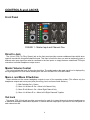
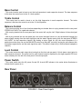
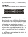
HeadAmp 6 Pro
6 CHANNEL HEADPHONE AMPLIFIER SYSTEM
USER’S GUIDE
1
2
IMPORTANT SAFETY INSTRUCTIONS – READ FIRST
This symbol, wherever it appears,
alerts you to the presence of uninsulated
dangerous voltage inside the enclosure. Voltage
that may be sufficient to constitute a risk of shock.
This symbol, wherever it appears, alerts
you to important operating and maintenance
instructions in the accompanying literature.
Please read manual.
Read Instructions:
Retain these safety and operating instructions for future reference. Heed all warnings printed here and on the equipment.
Follow the operating instructions printed in this user guide.
Do Not Open:
There are no user serviceable parts inside. Refer any service work to qualified technical personnel only.
Power Sources:
Only connect the unit to mains power of the type marked on the rear panel. The power source must provide a good
ground connection.
Power Cord:
Use the power cord with sealed mains plug appropriate for your local mains supply as provided with the equipment. If the
provided plug does not fit into your outlet consult your service agent. Route the power cord so that it is not likely to be
walked on, stretched or pinched by items placed upon or against.
Grounding:
Do not defeat the grounding and polarization means of the power cord plug. Do not remove or tamper with the ground
connection on the power cord.
Ventilation:
Do not obstruct the ventilation slots or position the unit where the air required for ventilation is impeded. If the unit is to be
operated in a rack, case or other furniture, ensure that it is constructed to allow adequate ventilation.
Moisture:
To reduce the risk of fire or electrical shock do not expose the unit to rain, moisture or use in damp or wet conditions. Do
not place a container of liquid on it, which may spill into any openings.
Heat:
Do not locate the unit in a place close to excessive heat or direct sunlight, as this could be a fire hazard. Locate the unit
away from any equipment, which produces heat such as: power supplies, power amplifiers and heaters.
Environment:
Protect from excessive dirt, dust, heat, and vibration when operating and storing. Avoid tobacco ash, drink spillage and
smoke, especially that associated with smoke machines.
Handling:
To prevent damage to the controls and cosmetics avoid rough handling and excessive vibration. Protect the controls from
damage during transit. Use adequate padding if you need to ship the unit. To avoid injury to yourself or damage to the
equipment take care when lifting, moving or carrying the unit.
Servicing:
Switch off the equipment and unplug the power cord immediately if it is exposed to moisture, spilled liquid, objects fallen
into opening, or the power cord or plug becomes damaged during a lightning storm or if smoke odor or noise is noted.
Refer servicing to qualified technical personnel only.
Installation:
Install the unit in accordance with the instructions printed in the user guide.
3
The ART HeadAmp 6 Pro
6 Channel Headphone Amplifier System
IMPORTANT SAFETY INSTRUCTIONS – READ FIRST ...............................................3
INTRODUCTION..........................................................................................................5
INSTALLATION...........................................................................................................5
AC Power Hookup ............................................................................................................................................................... 5
Analog Audio Connections .................................................................................................................................................. 5
CONTROLS and JACKS ..............................................................................................6
Front Panel .......................................................................................................................................................................... 6
Direct In Jack....................................................................................................................................................................... 6
Master Volume Control........................................................................................................................................................ 6
Mono L and Mono R Switches ............................................................................................................................................ 6
Out Jack............................................................................................................................................................................... 6
Bass Control ........................................................................................................................................................................ 7
Treble Control...................................................................................................................................................................... 7
Balance Control ................................................................................................................................................................... 7
Level Control ....................................................................................................................................................................... 7
Power Switch....................................................................................................................................................................... 7
Rear Panel........................................................................................................................................................................... 7
Balanced Main Inputs .......................................................................................................................................................... 8
Balanced Main Thru ............................................................................................................................................................ 8
Stereo Headphone Outputs................................................................................................................................................. 8
Stereo Aux Inputs ................................................................................................................................................................ 8
HEADAMP 6 PRO OPERATION ...................................................................................9
APPLICATIONS.........................................................................................................10
WARRANTY INFORMATION .....................................................................................12
SERVICE ...................................................................................................................13
HEADAMP 6 PRO SPECIFICATIONS .........................................................................14
List of Figures
FIGURE 1 - Master Input and Channel One.........................................................................................................6
FIGURE 2 - Rear Panel Inputs .............................................................................................................................7
FIGURE 3 - Rear Panel Headphone Outputs and Aux Inputs..............................................................................8
FIGURE 4 - Headphone Distribution Application................................................................................................10
FIGURE 5 - “More Me” Foldback Application .....................................................................................................11
4
INTRODUCTION
The ART HeadAmp 6 Pro is a six-channel stereo headphone amplifier that includes a six-channel auxiliary
input section that can be used to provide the popular “More-Me” function on each headphone mix. Each output
channel also features a dual function BALANCE control which will pan between LEFT & RIGHT sides of the
main signal bus, or vary the MIX between the main signal bus and the AUXILIARY input for that respective
channel.
Bass and treble controls are included on each output channel for fine-tuning the tone. Outputs include both
front and rear panel stereo 1/4-inch TRS jacks for ease of installation and quick patching capability. Two
MONO select buttons on each channel select between four operating modes; 1) Stereo, 2) Mono Left, 3) Mono
Right, 4) Mono Both (Left & Right) for versatile monitoring solutions.
Input options include XLR and 1/4-inch TRS balanced inputs with matching “Thru” jacks for bridging multiple
HeadAmp 6 Pro units. An additional front panel stereo 1/4-inch TRS jack for quick patch override of the rear
panel inputs is included for quick insertion of any stereo source. Eight-segment LED level indicators provide
visual feedback of the signal level on all channels as well as the main signal bus.
INSTALLATION
The HeadAmp 6 Pro may be used in a wide variety of applications and environments. Its rack-mountable
steel and aluminum enclosure is both attractive and designed for continuous professional use. Mounting
location is not critical. However, for greater performance reliability we recommend that you not place the unit
on top of power amps or other sources of extreme heat, or strong magnetic fields.
AC Power Hookup
The HeadAmp 6 Pro has an internal power supply. Only connect the unit to mains power of the type marked
on the rear panel. The power source must provide a good ground connection, and the ground pin on the mains
plug should never be defeated.
Analog Audio Connections
Audio connections to and from the HeadAmp 6 Pro are:
Rear Balanced Inputs and Outputs:
[XLR]
Pin 2 = Pos(+), Pin 3 = Neg (-), Pin 1 = Ground
[1/4-inch]
Tip = Pos (+), Ring = Neg (-), Sleeve = Ground
Rear Stereo Aux 1/4-inch Inputs:
Tip = Left, Ring = Right, Sleeve = Ground
Front Direct 1/4-inch Input:
Tip = Left, Ring = Right, Sleeve = Ground
Front and Rear Stereo Headphone 1/4-inch Outputs:
Tip = Left, Ring = Right, Sleeve = Ground
5
CONTROLS and JACKS
Front Panel
FIGURE 1 - Master Input and Channel One
Direct In Jack
The 1/4-inch TRS (Tip, Ring, Sleeve) jack on the front panel provides a stereo unbalanced input which when
used will override the rear panel balanced inputs. This input is useful for when you want to temporarily insert a
different main input signal from what is connected to the rear inputs, or simply make an unbalanced TRS style
connection to another headphone output source.
Master Volume Control
This control adjusts the level of the main signal bus. The audio level on the main signal bus is displayed by
the eight-segment LED level meter located just to the left of the MASTER VOLUME control.
Mono L and Mono R Switches
These switches set the stereo headphone outputs to one of four operating modes. (This affects only the
headphone outputs and occurs post (after) the mixing, level, and tone control sections.)
1) Both Switches Out = Stereo
2) Mono L In & Mono R Out = Mono Left Channel Only
3) Mono R In & Mono L Out = Mono Right Channel Only
4) Mono L In & Mono R In = Mono Left & Right Channels Together
Out Jack
This stereo TRS 1/4-inch jack provides a connection for each of six output channels to stereo headphones or
to additional headphone distribution amplifiers. A second identical output jack is provided on the rear panel for
each channel as well.
6
Bass Control
This control can be used to boost or cut the low frequencies in each respective channel. The bass response
is flat when the control is set to the 12 o’clock position.
Treble Control
This control can be used to boost or cut the high frequencies in each respective channel. The treble
response is flat when the control is set to the 12 o’clock position.
Balance Control
This control provides one of two functions depending on whether there is a plug inserted into the rear panel
STEREO AUX INPUT for a particular channel.
With no plug inserted into the rear panel jack, the control will vary the Left / Right balance of the main signal
bus.
With a plug inserted into the rear panel jack, the control changes function to vary the balance between the
stereo signals coming from the main signal bus and the stereo signals coming from the rear panel STEREO
AUX INPUT for that respective channel. (By feeding a return signal for only the vocal microphone of a
particular musician they can use the BALANCE control as a ‘More Me” control by varying the mix between their
microphone signal alone, and the main signal bus audio. This effect is heard only in that individual headphone
channel.)
Level Control
This control varies the audio output level coming from the front and rear panel 1/4-inch stereo output jacks for
each respective channel. The audio level for each channel output is displayed by the eight-segment LED level
meter located just to the left of the front panel 1/4-inch output jack.
Power Switch
This rocker switch turns the AC power On and Off. A small LED indicator in the rocker button illuminates to
indicate that the power is on.
Rear Panel
FIGURE 2 - Rear Panel Inputs
7
Balanced Main Inputs
These XLR and 1/4-inch TRS jacks are active balanced and are used for line level signals. The gain
sensitivity is identical for both the XLR and 1/4-inch TRS jacks. (NOTE: the front panel DIRECT IN jack
overrides these inputs when it is used.)
Balanced Main Thru
These XLR and 1/4-inch TRS jacks are hardwired in parallel with the corresponding BALANCED MAIN
INPUT jacks. The BALANCED MAIN THRU jacks are useful for daisy chaining multiple HeadAmp 6 Pro units
together.
FIGURE 3 - Rear Panel Headphone Outputs and Aux Inputs
Stereo Headphone Outputs
These stereo TRS jacks are the main outputs for each channel of the headphone amplifier. They are wired in
parallel with the corresponding output jacks on the front panel. Either front panel, rear panel, or both front and
rear panel outputs can be used simultaneously to drive headphones or they can be used as feeds to additional
headphone amplifiers in a distributed audio network. (NOTE: The HeadAmp 6 Pro is optimized to drive typical
headphone load impedances of 32 to 600 Ohms. It is not recommended to drive total impedances lower than
16 Ohms however it can be done and will result in limited maximum output power, and possible clipping
distortion depending on the output level and load. When driving multiple headphones from an individual output
channel of the HeadAmp 6 Pro (paralleling), the available output power is split among the various headphones,
and due to the combined load impedances the output may also become limited by premature clipping of the
output signal. Most modern headphones are mid to high impedance and require only milliwatts to achieve full
acoustic output so this should rarely be a problem. If it is a problem simply lower the total count of headphones
on a particular channel in order to raise to total load impedance as seen by the channel output.)
There is no direct relationship between headphone load impedance and SPL output. The relevant
specification that determines acoustic output is the sensitivity spec of the headphone, i.e. how much SPL it will
put out for a given level of input signal, usually rated at 1 mW. Sensitivity is determined by the overall design
and construction of the transducer. Typically the power required is about 1/1000th of the equivalent amplifier
power required to drive a speaker. Therefore typical headphone amplifiers provide power levels in the 10 to 20
mW range in order to achieve a very reasonable SPL output. Even an 8 Ohm headphone (if you can find one
since they are rare) can be driven to full SPL output by the HeadAmp 6 Pro if it has a high enough sensitivity,
regardless of the fact that the output voltage swing will be limited due to the overload protection circuitry.
Stereo Aux Inputs
These stereo TRS jacks provide a means of inserting a direct stereo signal into an individual headphone
channel. When a plug is inserted into an AUX INPUT jack the BALANCE control for that particular channel
changes function to become a balance (or mix) control adjusting the mix between the signal coming into the
STEREO AUX INPUT and the main signal bus.
8
HEADAMP 6 PRO OPERATION
Start with the MASTER VOLUME and LEVEL controls on all channels set fully counter-clockwise. Set the
BASS, TREBLE, and BALANCE controls to their 12 o’clock positions. Set all mono switches to their “OUT”
position.
Using the appropriate balanced or unbalanced cables, (unbalanced cables will work in the rear panel inputs
as well, but with the remote possibility of increased noise), connect the rear panel BALANCED MAIN INPUTs
to the audio monitor signal source to be distributed to the headphones. Alternatively connect the audio signal
source to the front panel DIRECT IN jack using a stereo TRS 1/4-inch plug.
If connecting more than one HeadAmp 6 Pro to the same audio monitor signal source, simply daisy-chain the
units by connecting from the BALANCED MAIN THRU connectors of the first unit to the BALANCED MAIN
INPUT connectors of the next unit, etc. (NOTE: Daisy chaining only works with the rear panel connectors. The
front panel DIRECT IN jack only feeds its respective HeadAmp 6 Pro unit directly.)
Connect headphones, or leads to additional headphone amps, (like the ART HeadAmp 4) to either the front
or rear panel HEADPHONE OUTPUT jacks (or both) using stereo 1/4-inch TRS plugs.
If using the HeadAmp 6 Pro Auxiliary Mixer function, connect the stereo signals that are to be mixed into
individual output channels to the appropriate rear panel STEREO AUX INPUT jacks using a stereo 1/4-inch
TRS plug. (NOTE: For a mono signal use a TRS plug with the Tip and Ring tied together, or use one of the
front panel MONO buttons to create a mono output to the headphones.) The AUX INPUT signal will only be
heard in that individual channel depending on the position of the BALANCE and LEVEL controls for that
particular channel.
Turn on the POWER switch and with the audio monitor signal active and playing increase the MASTER
VOLUME control to achieve a reading on the MASTER LED bar-graph level indicator which is high enough to
light the green and yellow LEDs yet avoid lighting the RED CLIP LED on loud passages and audio peaks.
Doing this will assure that a strong signal is available to drive each of the six individual channel amplifiers, and
subsequently each channel amplifier will be able to run with less gain (a lower setting of the LEVEL control),
thereby helping to optimize the signal-to-noise ratio at the outputs.
Next set the LEVEL control on each channel to a comfortable listening level for the particular headphones
being used.
Set the BASS, TREBLE, and BALANCE controls to listening preference.
NOTE: When using the Auxiliary Mixer to add a signal such as a direct vocal into an individual headphone
channel in order to enhance that particular vocal in the mix (providing “More Me”) for the person listening to
that headphone channel, the relative phase of the signal coming into the STEREO AUX INPUT will determine
whether the STEREO AUX INPUT signal sums or subtracts from the main signal bus. The “More Me” effect will
only result if the two signals add together in phase. If they are antiphase (180 degrees out of phase), the
STEREO AUX INPUT signal will actually subtract the vocal out of the mix in the headphones for that one
channel. Most consoles and microphone preamps will have a phase invert switch with which to set the desired
operating mode.
9
APPLICATIONS
FIGURE 4 - Headphone Distribution Application
10
FIGURE 5 - “More Me” Foldback Application
11
WARRANTY INFORMATION
Limited Warranty:
Applied Research and Technology will provide warranty and service for this unit in accordance with
the following warrants:
Applied Research and Technology, (A R T) warrants to the original purchaser that this product and
the components thereof will be free from defects in workmanship and materials for a period of three
years from the date of purchase. Applied Research and Technology will, without charge, repair or
replace, at its option, defective product or component parts upon prepaid delivery to the factory
service department or authorized service center, accompanied by proof of purchase date in the form
of a valid sales receipt.
Exclusions:
This warranty does not apply in the event of misuse or abuse of the product or as a result of
unauthorized alterations or repairs. This warranty is void if the serial number is altered, defaced, or
removed.
A R T reserves the right to make changes in design or make additions to or improvements upon this
product without any obligation to install the same on products previously manufactured.
A R T shall not be liable for any consequential damages, including without limitation damages
resulting from loss of use. Some states do not allow limitations of incidental or consequential
damages, so the above limitation or exclusion may not apply to you. This warranty gives you specific
rights and you may have other rights, which vary, from state to state.
For units purchased outside the United States, an authorized distributor of Applied Research and
Technology will provide service.
12
SERVICE
The following information is provided in the unlikely event that your unit requires service.
1) Be sure that the unit is the cause of the problem. Check to make sure the unit has power, all
cables are connected correctly, and the cables themselves are in working condition. You may want to
consult with your dealer for assistance in troubleshooting or testing your particular configuration.
2) If you believe the ART unit is at fault, go to www.artproaudio.com. You may contact Customer
Service for more assistance, or directly request a Return Authorization for service in the “resources”
area of the website.
3) If you are returning the unit for service, pack the unit in its original carton or a reasonable
substitute. The original packaging may not be suitable as a shipping carton, so consider putting the
packaged unit in another box for shipping. Print the RA number clearly on the outside of the shipping
box.
4) Include, with your unit, a note with the RA number and your contact information including a daytime
phone number, preferably attached to the top of the unit.
Fill in the following information for your reference:
Date of purchase
___________________
Purchased from
___________________
Serial number
___________________
13
HEADAMP 6 PRO SPECIFICATIONS
Input Impedance
Balanced Main Input XLR and 1/4-inch TRS Jacks....................40K Ohm Balanced
Direct In TRS Jack .....................................................................9.9K Ohm
Stereo Aux Input TRS Jacks ......................................................≤ 21K to ≥ 15K Ohm
CMRR @ 1KHz ..........................................................................≥ 40dB
Output Impedance
Headphone output......................................................................≤ 12 Ohms
Frequency Response
With Tone Controls Set Flat .......................................................20 Hz – 50 KHz +0, -2dB
High Frequency EQ ....................................................................± 12dB @ 10 KHz Shelving
Low Frequency EQ.....................................................................± 12dB @ 100 Hz Shelving
Maximum Input Level
...................................................................................................+21.5dBu
Dynamic Range
Ref: 130mW @ 600 Ohms (unit set to max gain) .......................≥101 dB (typical)
Maximum Gain
@ 1KHz With Tone Controls Set To Flat....................................25.6 dB
Maximum Output Level
600 Ohm Headphones @ 1 KHz ................................................150 mW
32 Ohm Headphones @ 1 KHz ..................................................500 mW
8 Ohm Headphones @ 1 KHz ....................................................150 mW
Dimensions (H x W x D)
...................................................................................................1.75 Inches x 19.0 Inches x 7.55 Inches
...................................................................................................44.5 mm x 482.6 mm x 190.5 mm
Weight
...................................................................................................6.8 lbs. 3.1 kg.
Power Requirements
Input ...........................................................................................USA – 105-125 VAC AC 60 Hz
Consumption ..............................................................................60 Watts Maximum - 18 Watts Idle
..................................................................................Export units configured for country of destination.
Ref: 0 dBu = 0.775VAC RMS
ART maintains a policy of constant product improvement. ART reserves the right to make changes in design or make
additions to or improvements upon this product without any obligation to install the same on products previously
manufactured. Therefore, specifications are subject to change without notice.
14
15
www.artproaudio.com
E-mail: [email protected]
© 2008 Applied Research & Technology
806-5004-101
16