1
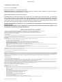
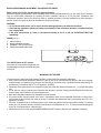
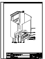
INSTALLATION, AND MAINTENANCE MANUAL FOR GAS FIRED, ONLY HEATING WALL-HUNG BOILERS (SYSTEM BOILERS) Model RS 20 E - RS 24 E - RS 30 E TYPE C ROOM SEALED CE 0063 - 0694 Technical Specification RADIANT BRUCIATORI S.p.A. Montelabbate (PU) ITALY ENGLISH By Technical Department INDEX INSTALLATION INSTRUCTIONS AND WARNINGS page 1 TECHNICAL DATA page 2 OVERALL DIMENSIONS - EXHAUST FLUE SYSTEM page 3-4 GENERAL INSTALLATION REQUIREMENTS page 5 BOILER INSTALLATION page 7 ELECTRICAL CONNECTIONS page 9; 15-16 BOILER CONTROL PANEL page 10 STARTING UP THE BOILER FOR THE FIRST TIME page 10 REGULATING THE GAS PRESSURE page 12 MULTIGAS OPERATION page 13 MAIN COMPONENTS page 14 MAINTENANCE page 17 UNPACKING page 17 FAULT FINDING CHART page 18 SHORT LIST OF COMPONENTS page 18 Installation Manual THE FRIENDLY POWER OF HEAT Thank you for choosing RADIANT Declaration for purposes of Art. 7 of Law 46 of 5 April 1990. RADIANT BRUCIATORI S.p.A. hereby declares that all of its products are constructed to industry standards as required by the Article in question and by Article 5 of the law in effect (D.P.R. no. 447/97). RADIANT BRUCIATORI S.p.A. products are type tested EC. All RADIANT boilers are constructed according to UNI - CIG (EC) norms. The materials used, such as copper, brass, and stainless steel form a compact, homogeneous, highly functional unit that is easy to install and simple to operate. The wall-mounted boiler is equipped with all of the approved accessories required to make it a true, independent heating plant for home heating and for the production of hot water for domestic needs. All boilers are fully inspected, and come with a certificate of quality signed by the inspector and with a warranty certificate. This booklet must be read carefully and stored in a safe place, accompanying the boiler at all times. RADIANT BRUCIATORI S.p.A. declines any and all responsibility for misinterpretations of this booklet deriving from any translations of same. RADIANT BRUCIATORI S.p.A. will not be responsible for non-observance of the instructions contained in this booklet or for the consequences of any action not specifically described herein. INSTALLATION INSTRUCTIONS - WARNINGS THIS INSTALLATION, USE, AND MAINTENANCE MANUAL IS AN ESSENTIAL AND INTEGRAL PART OF THE PRODUCT, AND MUST ALWAYS BE KEPT NEAR THE DEVICE. THE WARNINGS CONTAINED IN THIS SECTION ARE ADDRESSED BOTH TO THE USER AND TO INSTALLATION AND MAINTENANCE PERSONNEL. THE USER WILL FIND INFORMATION ON OPERATION AND LIMITS OF USE IN THE ACCOMPANYING MANUAL, WHICH SHOULD BE READ VERY CAREFULLY. STORE THE MANUAL CAREFULLY FOR FUTURE REFERENCE. 1) GENERAL WARNINGS INSTALLATION MUST BE PERFORMED IN OBSERVANCE OF CURRENT NORMS, ACCORDING TO THE CONSTRUCTOR’S INSTRUCTIONS, AND BY PROFESSIONALLY QUALIFIED PERSONNEL. THE INSTALLATION INSTRUCTIONS MANUAL MUST BE ALWAYS ACCOMPANY THE BOILER. PROFESSIONALLY QUALIFIED PERSONNEL ARE THOSE HAVING TECHNICAL COMPETENCE IN THE SECTOR OF APPLICATION OF THE DEVICE (CIVIL OR INDUSTRIAL), AND, IN PARTICULAR, THE CONSTRUCTOR’S AUTHORISED SERVICE CENTRES. INCORRECT INSTALLATION MAY CAUSE DAMAGE TO PERSONS, ANIMALS, OR PROPERTY, FOR WHICH THE CONSTRUCTOR ASSUMES NO LIABILITY. • • • • • • • • • • • After completely removing the packing, make sure that the contents are in perfect condition. In case of doubt, do not use the equipment. Consult the supplier. Packing materials (cardboard carton, wooden crate, nails, clips, plastic bags, polystyrene, etc.) are potentially dangerous and must be kept away from children. Before performing any cleaning or maintenance operation, turn off the unit by means of the mains switch and/or by means of the appropriate cut-off devices. Do not block the air intake or heat dissipation grates. In the event of breakdown and/or poor functioning of the device, turn it off and do not attempt to repair it or take any direct action. Refer to professionally qualified personnel only. Any repairs must be performed exclusively by a service centre authorised by the constructor, and with original spare parts only. Non-observance of the above instruction may compromise the safety of the device. To guarantee efficient and correct operation, the device should undergo period maintenance by professionally qualified personnel according to the constructor’s instructions. Whenever the device is to be put out of service, secure all potentially hazardous parts to prevent accidents or damage. If the device is sold or transferred to another owner, or if you move and leave the boiler, make sure that this booklet stays with the boiler so that it may be consulted by the new owner and/or by the installer. Use only original spare parts for all devices with optionals or kits (including electrical ones). WARNING: this device must be used for its intended purpose, i.e., heating and production of domestic hot water. Any other use is improper and therefore dangerous. The constructor will have no contractual or extracontractual liability for damage caused by incorrect installation and/or use or by non-observance of instructions supplied by the constructor. This device must be used exclusively with a sealed central heating system equipped with an expansion vessel. 2) WARNINGS REGARDING INSTALLATION Warranty expires 12 months from date of installation and in all cases no later than 18 months from date of construction. First start-up must be performed by authorised personnel only. For any operation on the hydraulic, gas, or electrical circuit regarding the heating unit, refer to authorised technicians only and use original spare parts only. Wall-mounted boilers are not to be installed in damp rooms, and must be protected against sprays or jets of water or other liquids to prevent malfunctions of the electrical and heating devices. They must not be exposed to direct steam from cookers, and nothing must be placed on top of them. This heating unit has been constructed to heat the home and to produce hot water. The constructor declines all responsibility for incorrect installation and/or use of the device. Do not leave the device on when it is not being used: close the gas cock and turn off the mains switch. If you smell gas in the room in which the device is installed, do not operate any electrical switches, telephones, or any other device that might cause a spark. Immediately open doors and windows to create an air current to clear the room. Close the main gas cock (at the meter) or the cylinder cock, and request immediate technical service. Do not tamper with the device. SYSTEMS WITH THERMOSTATS A by-pass must be installed in heating systems with radiators thermostats. As required by current norms, these devices must be installed by qualified personnel only, who must respect norms UNI-CIG 7129 and 7131 and revisions, fire department regulations, and requirements of the local gas company. Before installing the boiler, make sure that the water and heating systems are compatible with its output. The room must be properly ventilated by means of an air intake (see UNI 7129/92 and UNI 7129/95 FA). The air intake must be at floor level open flue only, at a point where it cannot be obstructed, and protected by a grate that does not reduce the useful section of flow. The use of air flows from adjacent rooms is permitted as long as such rooms are in depression with respect to the outside and as long as there are no wood-burning fireplaces or fans installed there. If the boiler is to be installed externally (for example, on balconies or terraces), make sure that it is protected against atmospheric agents to prevent damage to components and voiding of the warranty. In such cases we recommend building a heat compartment to protect the boiler against inclement weather. Check the technical data on the packing and on the plate located inside the front casing. Check that the burner is suitable for use with the type of gas available. Make sure that all pipes and connections are perfectly sealed and that there are no gas leaks. All pipework should be chemically flushed to remove any residues that might negative effect the operation of the boiler. 3) GENERAL WARNINGS BASED ON TYPE OF POWER SUPPLY POWER SUPPLY Electrical safety is achieved only when the device is correctly and efficiently earthed as per current safety norms (IEC 64-8 Electrical Part). • This fundamental safety requirement must be checked. In case of doubt, request a check of the electrical system by professionally qualified personnel. The constructor will not be liable for any damage caused by lack of or improper earthing of the system. • Have professionally qualified personnel check that the electrical system is adequate for the maximum absorbed power of the device (indicated on the plate). In particular, make sure that the section of the system wires is suitable for the maximum absorbed power of the device. • Do not use adapters, multiple sockets, and/or extension cords to power the device from the electrical mains. • Provide a unipolar switch as required by current safety regulations to connect the device to the mains. • The use of any electrical device requires the observance of some fundamental rules, such as: • do not touch the device with wet or damp parts of the body and/or with bare feet • do not pull on electrical cables • do not expose the device to atmospheric agents (rain, sun, etc.) unless specifically provided for • do not allow the device to be used by children or anyone unfamiliar with its operation • The power cable must not be replaced by the user. • If the cable becomes damaged, turn off the device and have the cable replaced by professionally qualified personnel only. • If you decide not to use the device for an extended length of time, turn off the mains switch that feeds all components of the system using electrical energy (pumps, burner, etc.). SYSTEM BOILER – Cod. 99951NA – November 2002 1 Installation Manual TECHNICAL DATA Type C devices are devices in which the combustion circuit (air intake, combustion chamber, exchanger, combustion exhaust) is sealed off from the place where they are installed. CENTRAL HEATING sealed combustion circuit type C32 Coaxial vertical C12 Coaxial horizontal C52 Double Technical data MODELS Maximum rated input KCal/h Kw BTU/hr KCal/h Kw BTU/hr KCal/h Kw BTU/hr KCal/h Kw BTU/hr bar bar bar °C Litres mm. mm. mm. Kg. Minimum rated input Maximum working output Minimum working output Max. working pressure (heating) Max. working pressure (water) Min. working pressure (heating) Max. heating temperature Expansion vessel capacity (initial pressure 1 bar) Width Height Depth Weight Flue diameter Flow/return connections Cold water connections Hot water connections Gas connections Electrical connection 50 Hz Power supply Burner jets NP 13 G20 Burner jets NP 13 G30 Burner jets NP 17 G20 Burner jets NP 17 G30 Gas category: IT II2H3 SYSTEM BOILER – Cod. 99951NA – November 2002 Ø RS 20 E RS 24 E RS 30 E 22900 26.60 90867 11000 12.80 43648 20900 24.34 82931 9450 11 37498 3 6 0.3 80 6 450 790 320 42 100/60 80/80 ¾” ½” ½” 230 150 1.25 0.75 25628 29.8 101692 15000 17.5 59520 23090 26.85 91621 12900 15 51187 3 6 0.3 80 6 450 790 320 42 100/60 80/80 ¾” ½” 29670 34.50 117731 16340 19 64837 27440 31.90 108882 14560 16.90 57774 3 6 0.3 80 10 450 790 320 45 125/80 80/80 ¾” ½” Ø Ø Ø Ø ½” V 230 W 150 Ø 1.25 Ø 0.77 Ø Ø Gas supply pressure: G20 20 mbar / G30/31 29-30/37 mbar FORCED CIRCULATION 2 ½” 230 150 1.20 0.75 Installation Manual TYPE C WALL-MOUNTED BOILERS SEALED COMBUSTION CIRCUIT: = 100 = 60 100 60 450 870 Kit A. Horizontal coaxial exhaust flue system with 360° rotation. It allows the flue exhaust and the air intake directly to an external wall. . N.B.: To insert a bend in the flue, reduce total flue length by 0.8 m. F 125 320 80 101 46 80 51 101 A 182 790 948 24 R G 51 101 F A Kit B. Double exhaust/emission twin flue system with 360° rotation. It allows the flue exhaust into a flue duct and the air intake directly from an external wall. N.B.: To insert a bend in the flue, reduce total flue length by 1.5 m. R RETURN ¾” G GAS 1/2" F COLD WATER INLET 1/2" A HEATING FLOW ¾” 17 790 120 924 G 80 R 24 17 790 894 790 182 125 320 101 46 NOTE: USE ORIGINAL RADIANT APPROVED FLUE KIT SYSTEMS, FLUE ACCESSORIES AND FLUE DIAPHRAGMS ONLY. APPROVED RADIANT FLUE DIAPHRAGMS AND ADJUSTMENT TABLES ARE SUPPLIED WITH RADIANT ORIGINAL FLUE KIT SYSTEMS. SYSTEM BOILER – Cod. 99951NA – November 2002 3 TYPE C WALL-MOUNTED BOILERS SEALED COMBUSTION CIRCUIT: 80 125 80 125 Installation Manual 790 Kit G. Horizontal coaxial exhaust flue system with 360° rotation. It allows the flue exhaust and the air intake directly to an external wall. . N.B.: To insert a bend in the flue, reduce total flue length by 0.8 m. G F 125 320 80 101 46 80 51 101 A 80 R 24 17 790 182 182 790 790 120 R RETURN ¾” G GAS 1/2" F COLD WATER INLET 1/2" A HEATING FLOW ¾” 17 24 R G 51 101 F A Kit B. Double exhaust/emission twin flue system with 360° rotation. It allows the flue exhaust into a flue duct and the air intake directly from an external wall. N.B.: To insert a bend in the flue, reduce total flue length by 1.5 m. 125 320 101 46 NOTE: USE ORIGINAL RADIANT APPROVED FLUE KIT SYSTEMS, FLUE ACCESSORIES AND FLUE DIAPHRAGMS ONLY. APPROVED RADIANT FLUE DIAPHRAGMS AND ADJUSTMENT TABLES ARE SUPPLIED WITH RADIANT ORIGINAL FLUE KIT SYSTEMS. SYSTEM BOILER – Cod. 99951NA – November 2002 4 Installation Manual GENERAL INSTALLATION REQUIREMENTS GAS SAFETY It is the law that all gas appliances are installed by a CORGI registered installer (you can check this by contacting corgi on 01256.372200) in accordance with the regulations listed below. Failure to install appliances correctly could lead to prosecution. It is in your own interest and that of safety to ensure that the law is complied with. Failure to have your appliance installed to comply with the installation instructions and the requirements listed below could invalidate your guarantee. RELATED DOCUMENTS The installation of the boiler must be in accordance with the relevant requirements of the Gas Safety regulations, Building regulations, I.E.E. regulations and the bylaws of the local water authority. It should be in accordance also with any relevant requirements of the local authority and the relevant recommendations of the following British Standard Codes of Practice: B.S 6400: BS 5376: BS 5449: CP 342: BS 5440: BS 5446: 1985 & B.S. 6891 : 1988. Selection and Installation of Gas Space Heating ( 1 and 2 family gases) Part 2: Boilers of rated input not exceeding 60 Kw Central Heating for domestic premises Part 1: Forced circulation Hot Water System Centralised Hot Water Supply BS 6700 : 1987 Part 2: Buildings other than individual Flues and air supply for Gas Appliances of rated input not exceeding 60 Kw (1 and 2 family gases) Part 1: Flues Part 2: Air Supply 1990: Installation of Gas Hot Water supplies for domestic purposes GAS SUPPLY Service Pipes: The local gas region should be consulted at the installation planning stage in order to establish the availability of supply of gas. An existing service pipe must not be used without prior consultation with the local gas region. Meters: A gas meter is connected to the service pipe by the local gas region or local gas region contractor. An existing meter should be checked to ensure that it is capable of passing an additional 3.4 m3/hr (125 ft/hr) before the appliance is installed. The meter outlet governor should ensure a nominal dynamic pressure of 20m Bar, (8 in wg) at the boiler. Installation pipes should be fitted in accordance with BS6891.1988. Pipework that supplies the boiler must be a 22 mm. ininterrupted supply from meter to the isolation cock of the boiler. The complete installation must be tested for soundness as described in the above code, BS 6400: 1985 & BS6891. IMPORTANT: BOTH THE USER AND THE MANUFACTURER RELY UPON THE INSTALLER, WHOSE JOB IS TO INSTALL THE BOILER AND CONNECT IT TO A CORRECTLY DESIGNED HEATING SYSTEM. THE INSTALLER SHOULD ACQUAINT HIMSELF WITH THE CONTENTS OF THIS PUBLICATION AND THE RELEVANT BRITISH STANDARDS CONCERNING INSTALLATION REQUIREMENTS. LOCATION OF BOILER In siting the combination boiler, the following limitations MUST be observed: The position selected for installation should be within the building, and MUST allow adequate space for installation, servicing and operation of the combination boiler, and for air circulation around it. The boiler is not suitable for external installation. This position MUST also allow for a suitable flue termination to be made. The boiler must be installed on a flat vertical wall which is capable of supporting the weight of the combination boiler, and any ancillary equipment. If the boiler is to be fitted in a timber framed building it should be fitted in accordance with the British Gas publication "Guide for Gas Installations in Timber Frame Housing, Reference IGE/UP/6. If in doubt, advice must be sought from the local region of British Gas. The boiler may be installed in any room or internal space, although particular attention is drawn to the requirements of the current I.E.E. Wiring Regulations, and in Scotland the electrical provisions of the Building Regulations applicable in Scotland, with respect to the installation of the boiler in a room or internal space containing a bath or shower. Where a room-sealed appliance is installed in a room containing a bath or shower, any electrical switch or appliance control utilising mains electricity must be so situated that it cannot be touched by a person using the bath or shower. A compartment used to enclose the combination boiler MUST be designed and constructed specifically for this purpose. An existing cupboard, or compartment, may be used provided it is modified accordingly. Where installation will be in an unusual location, special procedures may be necessary. BS 6798 gives detailed guidance on this aspect. For clearances to be made available for installation and servicing, see Sections 5.2.2. to 5.2.4. SYSTEM BOILER – Cod. 99951NA – November 2002 5 Installation Manual FLUE POSITION IMPORTANT: THE FLUE SYSTEM SHALL BE INSTALLED IN ACCORDANCE WITH THE RECOMMENDATIONS CONTAINED IN BS 5440:1. The boiler MUST be installed so that the terminal is exposed to the external air. It is important that the position of the terminal allows free passage of air across it at all times. If the terminal discharges into a pathway or passageway check that combustion products will not cause nuisance and that the terminal will not obstruct the passageway. In certain weather conditions a terminal may emit a plume of steam. Positions where this would cause a nuisance should be avoided. IMPORTANT REQUIREMENT: The correct dimensional relationship between the terminal and any obstruction, openable window or ventilator as shown in Fig 1 pag.7 It is ESSENTIAL TO ENSURE, in practice, that products of combustion discharging from the terminal cannot re-enter the building, or any other adjacent building, through ventilators, windows, doors, other sources of natural air infiltration, or forced ventilation/air conditioning systems. If this should occur, the appliance MUST BE TURNED OFF IMMEDIATELY and the local gas region consulted. Where the lowest part of the terminal is fitted less than 2m (6.6ft) above a balcony, above ground, or above a flat roof to which people have access, the terminal MUST be protected by a purpose designed guard. Where the terminal is fitted within 850mm (34in) of a plastic or painted gutter, or 450mm (18in) of painted eaves, an aluminium shield of at least 1000 mm (40in) long should be fitted to the underside of the gutter painted surface. The air inlet/products outlet duct and the terminal of the boiler MUST NOT be closer than 25mm (1in) to combustible material. TERMINAL POSITION 300 min TERMINAL ASSEMBLY PROPERTY BOUNDARY LINE L TOP VIEW REAR FLUE K B.C G N D G J M E A D H,I A F F G Fig. 1 A B C D E F G H I J K L M N Directly below an openable window, air vent or any other ventilation opening. 300 mm Below gutter, drain pipes or soil pipes. 25 mm Below eaves. 25 mm Below balcony or carport roof. 25 mm From vertical drain pipes or soil pipes. 25 mm From internal or external corners. 25 mm Above adjacent ground, roof or balcony level. 300 mm From a surface facing the terminal. 600 mm Facing the terminals. 1200 mm From opening (door, window)in the carport into dwelling. 1200 mm Vertically from a terminal on the same wall 1500 mm Horizontally from a terminal on the same wall 300 mm Above an opening, air brick, opening window etc. 300 mm Horizontally to an opening, air brick, opening window etc. 300 mm SYSTEM BOILER – Cod. 99951NA – November 2002 6 Installation Manual BOILER INSTALLATION - MINIMUM DISTANCES FOR FIXING TO WALL To allow access inside the boiler for maintenance operations, the minimum distances shown in fig. 2 must be kept. 60 450 60 100 60 = 118 80 125 320 max. 3000 790 870 24 17 790 894 450 182 MINIMUM DISTANCES IN mm. 80 80 KIT B 182 120 17 790 924 790 948 60 100 = 80 To aid installation, the boiler is supplied with a template (see fig. 1) for advance location of connections to pipes. In this way, you may simply hook up the boiler when the wall fixings are completed (fig.1). KIT C KIT A 450 24 To install the boiler proceed as follows (see fig.2): 1. Use a spirit level (min. 25mm in length) to draw a line on the wall where the boiler is to be installed. 2. Position the top of the template on the line Fig. 1 drawn with the spirit level, keeping to the recommended distances; now mark the two points where the two fixing screws or brackets are to go, then mark the points where the water and gas connections will go; 3. Take away the template and proceed by connecting up the connectors supplied with the boiler to the hot and cold water supplies, gas system and heating pipes; 4. Mount the boiler on the wall using the fixing screws or brackets and make all necessary pipe connections. 125 320 Fig. 2 A FIXING JIG W/VALVES G R R HEATING RETURN ¾” G GAS ½” F COLD WATER INLET ½” A HEATING FLOW ¾” WATER CONNECTIONS To facilitate installation, the boiler is equipped with a fittings kit. Fig. 3 A IMPORTANT: FITTINGS KIT G Before connecting the heating system pipes, carefully clean the system to R prevent residual dirt from entering into circulation and negatively affecting boiler function. Install a funnel with discharge under the safety valve (calibrated to 3 bar) to collect water in case of leaking due to overpressure. No safety valve is needed for the domestic hot water circuit, but if the cold main inlet pressure exceeds 5 bar a pressure reducing value should be fitted. ADVICE AND SUGGESTIONS FOR DEALING WITH VIBRATIONS AND NOISE FROM THE SYSTEM avoid using pipelines of reduced diameter; avoid the use of tight bends and adapters in important sections; clean out the system thoroughly before connecting up the boiler in order to eliminate any residue left in the pipes and radiators. N.B.: Make sure that the water and heating pipes are not used as earth connections for electrical apparatus. SYSTEM BOILER – Cod. 99951NA – November 2002 7 Installation Manual GAS CONNECTIONS The gas supply must be connected up by a corgi registered fitter. The following standards must be complied with: UNICIG 7131/72 and UNICIG 7129/92 (of 21/04/93) Before installing the boiler, make sure of the following: • the pipeline must be of an adequate section and length to carry the flow required and must be fitted with all safety devices and measures prescribed by current norms; • before turning on the boiler make sure the type of gas which it is designed to run on is available • the gas supply pressure must lie within the values shown on the plate it is recommended that the gas supply pipeline should be checked for residual obstructions before installing the boiler; • where the internal gas supply pipe meets the boiler, the gas isolation cock supplied with the boiler must be fitted; • check thoroughly that the gas inlets and outlets are properly sealed. • conversion to allow the boiler to run on LPG to natural gas or vice versa must be carried out by a qualified gas fitter in accordance with law no.46 of 5th March ‘90 (see p.18). Table n°1 ANTI-FREEZE SYSTEM Antifreeze Ethylene glycol (%) volume 10 20 30 40 50 60 ANTI-FROST SYSTEM Radiant boilers are equipped with an AntiFreeze system which comes into operation when the temperature falls to 5° C (Heating sensor) and 4° C (Hot water sensor) and protects the boiler down to – 2°C external temperature. To protect the internal Radiators, a room thermostat or remote control must be fitted. Temperature freezing point (°C) -4 -10 - 17 - 27 - 40 - 47 boiling point (°C) 101 102 104 106 109 114 mod. RS 20 E RS 24 E NOTE: The frost system will only come into operation if the boiler is filled with water, and connected to a live gas supply, with electrical supply and boiler controls in the “ON” position (With the Main switch turned to Summer or Winter position) ) and the gas supply turned on. FOR THE INSTALLER For boilers installed outdoors, where the temperature may drop below -2° degrees Centigrade, the system should be filled with antifreeze liquid by an authorised technician and a set of electrical heating elements should be fitted to protect the domestic hot water heat exchanger. ADVICE FOR THE SERVICE TECHNICIAN If the boiler is out of service because it is frozen, check that no parts have been locked in position by ice before putting it into operation. It is advisable to empty the boiler and the system in case of no operation for a long period. mod. RS 30 E Recommended percentage of glycol for temperatures down to - 8°C is 20%.The antifreeze liquid used must be of a good make and in a solution which has already been diluted to avoid the risk of uncontrolled dilution. SYSTEM BOILER – Cod. 99951NA – November 2002 8 Installation Manual ELECTRICAL CONNECTIONS The boiler works with 230 V 50 Hz AC current and has maximum input of 150 W. Connection to the electrical mains must be performed with a device having an omnipolar opening of at least 3 mm. Make sure the live and neutral connections conform to the diagram. A secure earth connection is compulsory. Fig. 1 NOT APPLICABLE FOR U.K. VT SHUKO MAINS PLUG 1 IMPORTANT 2 If you need to replace the power supply cable, use cable having the same characteristics: (HO5 W-F) 3x1.5 with maximum external diameter 9 mm.). Connect to the terminal block located in the instrument panel as follows: A. B. C. D. E. • • • Turn off the electrical power supply at the mains. Remove the boiler front casing. Undo the two side screws on the panel using the phillips screwdriver VT and turn it to the position shown in fig.1 (pos. 1). After pulling the panel downwards, undo the four rear screws on the housing and open the electrical control box by lifting the cover as shown in fig.1. With the electrical control box now open make the following connections: Connect the yellow/green wire to the terminal marked with the earth symbol “ “ (see fig.1). Connect the blue wire to the terminal marked with the letter “N”. Connect the brown wire to the terminal marked with the letter “L”. LIGHT BLUE Fig. 2 YELLOW/GREEN BROWN BLACK BROWN YELLOW/GREEN LIGHT BLUE BLACK BLACK Fig. 3 PT PT Fig. 4 TA TA OR N L Fig. 5 TA OR N L Fig. 6 CONNECTION OF ROOM THERMOSTAT NOTE: use low voltage room thermostats only. M M brown 3 2 1 blue 5 4 yellow Fig. 7 red brown 2 1 blue 3 yellow 5 4 red The thermostat wire must not be placed in the channel containing high tension wires, but must have its own line The room thermostat lead must not exceed 50m n length; minimum section 0.5 mm. Connection: after carrying out the operations described on page 15, proceed as follows: A. Insert the room thermostat lead into the PT entry point on the electrical control box TA along with all the other leads on the boiler. B. Move the bridge PT (see fig.1) from TA TA OR N L OR N L terminal TA to the free one next to it. C. Insert the thermostat wires (fig.2) one in terminal TA and the other in the one next to it occupied by bridge PT which you have just moved. If a timer is fitted as well as a room thermostat, carry out the electrical connections for the timer according to the indications in figures 3 (tipe clock + room thermostat) and 4 (time clock only). SYSTEM BOILER – Cod. 99951NA – November 2002 9 Installation Manual INSTRUMENT PANEL 3 2 1 LEGEND (see fig. 1) 1. SUMMER-WINTER ON-OFF SWITCH 2. HEATING TEMPERATURE ADJUSTMENT KNOB 3. SPACE FOR ADDING AN OPTIONAL TIMER SELF- DIAGNOSTIC LEGEND (see fig. 2) 4. WARNING: LACK OF WATER IN THE SYSTEM 5. WATER PRESSURE LEVEL 1 BAR 6. WATER PRESSURE LEVEL 1.5 BAR 7. WARNING: CHIMNEY SAFETY DEVICE ON R OPEN CHAMBER MODEL 8. WARNING: LOCK-OUT INDICATOR (FIXED LIGHTS ONLY – NO FLASHING) Fig. 1 ELECTRONIC WATER PRESSURE GAUGE 4 5 6 0.5 1 1.5 7 Fig. 2 STARTING UP THE BOILER FOR 1st TIME AIR VENT VALVE CAP After connecting up the water supply, before starting up the boiler, carry out the following procedures: AIR VENT VALVE Preliminary procedure CIRCULATING PUMP Do as follows: make sure the power supply for the boiler is the same as that stated on the plate (230V - 50Hz) and that the live, neutral and earth connections have been properly connected; make sure the type of gas being supplied is the same as the type for which the boiler has been tested and calibrated; PUMP CUP make sure the unit is properly earthed; Fig. 3 make sure there are no flammable liquids or materials in the immediate vicinity of the boiler; make sure that any shut-off valves in the heating circuit are open; open the gas cock and check the gas seals, making sure the counter shows no sign of leaks; in any case, double check by using a soapy solution and eliminate all eventual leaks. The checking procedure for the gas burner attachment is carried out with the boiler working; make sure the electrical mains switch is OFF; remove the front cover by pulling it forwards; undo the side screws and rotate the panel downwards FILLING THE SYSTEM Fill the heating system as follows, making sure that the gas cock is closed: • open the tap on the filling loop and fill the system until a pressure of 1.5 bar has been reached (light no. 6 fig.2) and then close the tap; • make sure the cap on the jolly valve is slightly loose to allow air to escape from the system (see fig. 3). • undo the cap on the circulation pump to eliminate any eventual air locks. It is a good idea to purge all radiators of air at this point too; • before starting up the boiler the water pressure must be checked again; if this is seen to be below 0.5 bar, bring it back up to 1.5 bar and then close the tap on the filling loop; • switch on the electrical power supply to the boiler; • turn the selector switch to the WINTER position (see fig.1), after a few seconds the pump will come into action; • once the boiler is working, if any noises are heard in the system, repeat the above air purging procedures until there is no air left in the system; • check there are no obstructions in the exhaust duct; SYSTEM BOILER – Cod. 99951NA – November 2002 10 Installation Manual • check the pressure in the system: if this has gone down, restore it until the pressure gauge shows 1.5 bar. Close the tap on the filling loop once this operation is completed; STARTING UP THE BOILER • open the gas cock; • turn on the boiler; • set the selector to winter; • make sure that 5 and 6 light are ON (fig.2 pag.10) on the boiler panel. If light no. 4 is ON, it means water deficiency in the system: fill the system until a pressure of 1,5 bar has been reached (light no. 6 ON; fig 2 pag. 10) and then close the tap. The automatic ignition system will turn the burner ON. It may be necessary to repeat the procedure a few times to purge air from the pipes. To repeat the ignition procedure in any case wait 3 minutes before turning the boiler off and on again, then try to ignite it once more; • calibrate the boiler; • after carrying out this operation, return the panel to its correct position and put the front casing back; REGULATING THE HEATING TEMPERATURE The heating temperature is regulated by turning knob 2 (fig.1 pag.10) to the temperature required, chosen from the different values printed around the selector. The temperature range goes from a minimum of 35°C to a maximum of 80°C. EMPTYING THE CENTRAL HEATING THE SYSTEM Whenever it is necessary to empty the system, proceed as follows: • turn off the main power supply switch; • wait for the boiler to cool down; • undo the system drain tap and use a container to collect the water that runs out; WARNING Please ensure that the boiler in commissioned in line with all BENCHMARK BOOKLET REQUIREMENTS. Failure to do this may in validate the guarentee. SYSTEM BOILER – Cod. 99951NA – November 2002 11 Installation Manual REGULATING THE MAX. AND MIN. MODULATION GAS PRESSURE A To regulate the maximum gas pressure to the burner proceed as follows: • insert a gauge into the pressure socket B (fig.1). • remove the aluminium protective cap from screw A (fig.1) counter-clockwise; • turn the boiler on with the selector turned to the winter position; • once ignited, set the "P1 MAX. HEAT" trimmer (fig.2) to the maximum and turn screw A (fig.1) on the stabiliser clockwise to increase pressure or counterclockwise to decrease pressure (see the table below for calibration pressures); • on completion, screw in the aluminium cap, protecting screw A, previously removed from the gas valve; • regulating the min. gas pressure: without removing the gauge and with the selector set to winter, set the "P1 MAX. HEAT" trimmer to the minimum heat by turning it counter-clockwise; • regulate the minimum pressure by turning the "P2 MIN. GAS" trimmer (see the table below for calibration pressures); • on completion, set the "P1 MAX. HEAT" trimmer back to the starting pressure; • remove the gauge, tighten the pressure socket B and make sure there are no gas leaks. C 40 30 D 20 10 MANOMETRO Fig. 1 VALVOLA GAS VK4105G1005 P1 P2 MAX.RISC. MIN.GAS TR2 TR1 FUSE 2A N.B. The "P1 MAX. HEAT" trimmer is factory set to 80% of the maximum nominal output during the testing stage. When the boiler is started up for the first time is must be regulated according to the thermal power of the system. To make adjustments use a flat head screwdriver and turn clockwise to increase or counter-clockwise to decrease. B Fig. 2 MIN. AND MAX. GAS PRESSURES Models: RS 20 E RS 24 E RS 30 E mbar mbar mbar SYSTEM BOILER – Cod. 99951NA – November 2002 NATURAL GAS G20 Min – Max 1.5 – 10.5 4.2 – 13.7 3.1 – 12.6 LIQUID BUTANE GAS G30 Min – Max 6.6 – 27.5 5 – 26.3 12 LIQUID PROPANE GAS G31 Min - Max 8 – 35.6 6 – 33.6 9 – 32 Installation Manual GAS TYPE CONVERSION GAS BURNER UNIT 1 Conversion of the boiler from natural gas to LPG and vice versa must be performed by qualified personnel only. Conversion is performed as follows: d) e) turn off the main power switch; close the gas cock; substitute the jets on the main burner as follows: undo the gas pipe 5 (fig.1) from the burner manifold using a size 24 spanner; separate the burner manifold 2 from the burner ramps 1 by undoing the 4 screws 3 using a cross head screwdriver; fit new jets 4 to the burner suitable for the type of gas the boiler will run on using a no. 7 spanner. The jets must be fitted with new gaskets; reassemble the entire burner unit. Use the soapy water method to check for gas leaks each time gas connections are dismantled and reassembled; replace the gas setting plate that indicates the type of gas and nominal pressure for the boiler. When converting the boiler to work with a different type of gas, remove the existing plate and replace it with the new one supplied in the conversion kit . calibrate the new max. and min. settings for the gas pressure. SLOW IGNITION ADJUSTMENT (fig. 2) This is a slow ignition regulator whose trimmer is factory set to the minimum. For adjustment proceed as follows: if turned clockwise the gas pressure at the burner increases on ignition while turning counter-clockwise decreases the gas pressure. 3 4 5 Fig. 2 Fig.11 Fig. P2 MIN.GAS CM1 TR2 TR1 FUSE 2A a) b) c) 2 Fig. 3 Link inserted on CM1 selector. Timing 0 min. Link disabled on CM1 selector. Timing 3 min. Fig. 4 SELECTOR SELECTOR Fig. 5 CM1 CM1 LINK TO ADJUST SLOW IGNITION This allows the various ignitions to be delayed once the boiler has reached the optimum temperature. CM1 link on main p.c.b. (fig.3) The timing range goes from 0 with the link inserted on CM1 selector (fig. 4), to 3 minutes with the link disabled on CM1 selector or eventually positioned on the side pin as shown in figure no,5. SYSTEM BOILER – Cod. 99951NA – November 2002 13 Installation Manual mod. RS 30 E mod. RS 20 E - RS 24 E 14 14 15 15 3 2 3 16 2 6 1 5 2 10 10 13 13 2 8 9 3 4 7 7 12 11 12 5 11 KEY 1. 2. 3. 4. 5. 6. 7. 8. 9. 10. 11. 12. 13. 14. 15. 16. MAIN HEAT EXCHANGER 20.000 – 24.000 kCal/h MAIN HEAT EXCHANGER 30.000 kCal/h CIRCULATING PUMP RSL 15/5 CIRCULATING PUMP RSL 15/6 GAS VALVE VK4105 LT.6 EXPANSION VESSEL 3 BAR SAFETY VALVE BURNER 13 R. BURNER 17 R. HEATING SENSOR WATER PRESSURE SWITCH WATER PRESSURE GAUGE LIMIT THERMOSTAT 95°C AIR PRESSURE SWITCH EXHAUST FAN LT.10 EXPANSION VESSEL SYSTEM BOILER – Cod. 99951NA – November 2002 14 5 Installation Manual ELECTRONIC PRINTED CIRCUIT BOARD SM 20013 + CONNECTORS Room sealed M3 M2 M1 M4 M7 M6 M5 ER 3 12 11 10 9 black 7 8 9 black-blue brown SR blue 2 black CIRUIT BOARD S4565QM 1012 C PAC TF 1 EA 8 7 6 5 4 3 2 + 1 - TS M2 M3 10 11 12 13 14 15 27 - SUMMER-WINTER SWITCH - ROOM THERMOSTAT - TIME CLOCK - IGNITION ELECTRODE - IONISATION ELECTRODE - AIR PRESSURE SWTICH - FAN 26 25 23 24 22 M5 brown E.I. TA OR EA ER PAR EV black - LINE - NEUTRAL - WATER PRESSURE SWITCH - MAIN SWITCH - HEATING SENSOR - PUMP - SAFETY THERMOSTAT grey KEY L N PAC IG SR P TS 6 light blue 5 N TA-OR L EV P NO NC PAR black brown blue brown 29 blue 28 black E/I IG blue C Switch brown POWER SUPPLY TERMINAL BLOCK IMPORTANT: RESPECT LIVE-NEUTRAL POLARITY M6 M4 16 SYSTEM BOILER – Cod. 99951NA – November 2002 17 18 19 20 21 15 M7 30 31 32 33 34 35 36 SYSTEM BOILER – Cod. 99951NA – November 2002 16 M7 32 M5 24 TL MF PWM T. AMB. E/I T. OFF SPIA PRIORITY BLOCK AND GPL-MET TERM. FUMI HIGT VOLTAGE CIRCUIT (220V AC) C3 M5 26 M5 27 THERMOSTATS MODULATION BLOCK SPIA RV EV LB R8 M7 30 8 7 6 5 4 3 D6 M7 33 no 12 11 10 9 M7 35 c SENSOR R6 nc HOT WATER R10 RV-C M7 34 M5 25 MAX HEAT. M6 28 M7 36 PF MIN. GAS C M6 29 RP-C M7 31 RT-C T. HEAT. ALLAR. H2O M4 16 M4 17 F T. SAN. N L IC TR LOW VOLTAGE CIRCUIT RP RT PRESS. ACQUA SPIA 1.5 BAR SPIA 1 BAR Installation Manual ROOM SEALED WIRING DIAGRAM WATER PRESSURE SWITCH SENSOR HEATING S4565QM 1012 2 1 Installation Manual MAINTENANCE To keep the boiler in efficient and safe operating condition, we recommend that the following checks are performed at least once a year (according to reference standards): • • • • • • • • • Check all seals on the gas components and replace gaskets to restore perfect seal as required. Check all seals on the water components and replace gaskets to restore perfect seal as required. Visually check combustion and the combustion chamber; dismantle and clean the burner if necessary. Check the primary exchanger and clean it if necessary Check functioning of the gas safety systems: the insufficient gas safety device (ionisation electrode for electronic ignition boilers); Check functioning of the heating safety systems: the safety thermostat for temperature limit, the safety for pressure limit: Check the flue exhaust safety device. Check the max. and min. gas pressure and the modulation. Check that the electrical connection conforms to the description in the instruction manual for the boiler. When dismantling the boilers casing, be careful when removing the side panels after having removed the front panel; the side panels are removed by undoing the lower and front fixing screws and then removing as shown in fig.1, lifting and then pulling away. The new side panels on the Midy series are connected to the A boiler frame by means of two hooks which correspond with two slots on the frame to ensure quick and efficient fixing. Fig. 1 B UNPACKING A. Set the packed boiler down on the floor making sure that the arrow is pointing downwards and remove the staples, opening the 4 flaps outwards. B. Turn the boiler 180° supporting it by hand. C. Lift the box. and remove the packing pieces. Lift the boiler by holding it at the back and proceed with installation. C N.B. It is recommended that the boiler be unpacked before installation. The manufacturer cannot be held responsible for any damage caused to the boiler due to incorrect handling of the boiler. IMPORTANT! The packing materials (cardboard) are recyclable. IMPORTANT! The inner packing materials (plastic bags, polystyrene foam, nails etc.) are potentially dangerous and must not be left within reach of small children. SYSTEM BOILER – Cod. 99951NA – November 2002 17 Fig. 2 Installation Manual SHORT LIST SYSTEM BOILER – Cod. 99951NA – November 2002 18 USER MANUAL Model RS 20 E / 40 - 60 TYPE C Model ROOM SEALED RS 24 E / 70 - 90 TYPE C ROOM SEALED TA02B101.B1203 Technical Specification RADIANT BRUCIATORI S.p.A. Montelabbate (PU) ITALY ENGLISH User Manual BOILER OPERATION AND ADJUSTMENT PROCEDURES FOR USERS Before turning on the boiler read the following warnings carefully . Make sure that the warranty booklet carries the stamp of the CORGI registered technician (you can check this by contacting corgi on 01256.372200) responsible for installing the boiler. Installation, starting up for the first time, adjustments and maintenance operations must all be carried out solely by qualified technicians. Incorrect installation may cause damage to persons, animals or property for which the manufacturer cannot be held liable. WARNING! ⇒ Do not start the boiler unless you are sure it has been thoroughly tested by an authorised technician. ⇒ Check that the regulations regarding air intakes and ventilation of the room where the boiler is installed have been fully complied with. ⇒ If the boiler should freeze up, under no circumstances attempt to turn it on but call the RADIANT HELP LINE immediately. LEGEND (see fig. 1) 1. 2. 3. 4. ON-OFF SWITCH BOILER THERMOSTAT KNOB WARNING: LOCK-OUT INDICATOR OPERATING/ POWER INDICATOR 3 4 Fig. 1 Turn ON/OFF switch to OFF position. If the boiler will not be used for long periods it is recommended that the gas cock under the boiler be shut off. 1 2 WARNINGS FOR THE USER To keep the boiler in efficient and safe operating condition, carefully follow the instructions listed below: Have normal maintenance performed at least once a year by one of our authorised service centres (a fee will be charged), combustion tests are necessary every two years and should again be carried out by a qualified technician authorized by the manufacturer (in accordance with D.P.R. 412 regulations, 26-08-93). Periodically check system pressure on the pressure gauge and check that pressure is between 0.5 - 1.5 bar with the system cold. Do not clean the casing or internal parts of the boiler with thinners or solvents. Cleaning should always be done using only soap and water and be carried out by authorised personnel. Never leave flammable materials in the immediate vicinity of the boiler. For greater comfort and more rational use of heat, it is advisable to install a room thermostat connected to a clock timer to turn the boiler on and off during the course of the day or week with two temperature levels (in accordance with D.P.R. 412 regulations, 26-08-93). The boiler is equipped with an anti-freeze system, which comes into operation when the temperature reaches 5°C (heating sensor) and 4°C (hot water sensor), protecting the boiler down to a temperature of -2°C. To protect the internal heating unit as well, fit a room thermostat or a remote control. Please ensure you have a fully completed BENCHMARK BOOKLET and this is kept with your installation instructions. SYSTEM BOILER – TA02B101.B1203 I RADIANT BRUCIATORI s.p.a. Via Pantanelli, 164/166 - 61025 Loc. Montelabbate (PU) Tel. +39 0721 9079.1 • fax. +39 0721 9079279 e-mail: tecnico@radiant • Internet: http://www.radiant.it UK – Radiant Helpline – 01329.828555 ALL DESCRIPTIONS AND ILLUSTRATIONS CONTAINED IN THIS LEAFLET HAVE BEEN CAREFULLY PREPARED BUT WE RESERVE THE RIGHT TO MAKE CHANGES AND IMPROVEMENTS IN OUR PRODUCTS WHITCH MAY AFFECT THE ACCURANCY OF THE INFORMATION CONTAINED IN THIS LEAFLET. E + OE ALL RIGHTS RESERVED. NO PART OF THIS DOCUMENT MAY BE REPRODUCED, SAVED IN STORAGE SYSTEMS OR TRANSMITTED IN ANY FORM OR BY ANY MEANS, WHETHER ELECTRONIC, MECHANICAL, PHOTOCOPYING, RECORDING OR OTHERS, WITHOUT THE MANUFACTURER'S PRIOR AUTHORISATION IN WRITING. TA02B101.B1203